

Digital Equipment COLORWRITER LSR 2000 Service Manual

COLORWRITER LSR 2000
PRINTER
SERVICE GUIDE
Part Number EK-LSRCW-SV.A01
Digital Equipment Corporation
Maynard, Massachusetts
This document was created with FrameMaker 4.0.4


First Printing, January 1996
Possession, use, or copying of the software described in this publication is authorized only pursuant to a valid written license from
Electronics for Imaging, Inc.
Electronics for Imaging, Inc. 1996. All rights reserved.
Legal Notices
ELECTRONICS FOR IMAGING, INC. MAKES NO WARRANTIES, EXPRESS OR IMPLIED, INCLUDING WITHOUT
LIMITATION THE IMPLIED WARRANTIES OF MERCHANTABILITY AND FITNESS FOR A PARTICULAR PURPOSE,
REGARDING THE APPLE SOFTWARE. ELECTRONICS FOR IMAGING DOES NOT WARRANT, GUARANTEE, OR
MAKE ANY REPRESENTATIONS REGARDING THE USE OR THE RESULTS OF THE USE OF THE APPLE SOFTWARE
IN TERMS OF ITS CORRECTNESS, A CCURACY , RELIABILITY , CURRENTNESS, OR O THER WISE. THE ENTIRE RISK
AS TO THE RESULTS AND PERFORMANCE OF THE APPLE SOFTWARE IS ASSUMED BY YOU. THE EX CLUSION OF
IMPLIED WARRANTIES IS NOT PERMITTED BY SOME STATES. THE ABOVE EXCLUSION MAY NOT APPLY TO
YOU.
IN NO EVENT WILL ELECTRONICS FOR IMAGING, ITS DIRECTORS, OFFICERS, EMPLOYEES OR AGENTS BE
LIABLE TO YOU FOR ANY CONSEQUENTIAL, INCIDENTAL OR INDIRECT DAMAGES (INCLUDING DAMAGES
FOR LOSS OF BUSINESS PROFITS, BUSINESS INTERRUPTION, LOSS OF BUSINESS INFORMATION, AND THE
LIKE) ARISING OUT OF THE USE OR INABILITY TO USE THE APPLE SOFTWARE EVEN IF ELECTRONICS FOR
IMAGING HAS BEEN ADVISED OF THE POSSIBILITY OF SUCH DAMAGES. BECAUSE SOME STATES DO NOT
ALLOW THE EXCLUSION OR LIMITATION OF LIABILITY FOR CONSEQUENTIAL OR INCIDENTAL DAMAGES,
THE ABOVE LIMITATIONS MAY NOT APPLY TO YOU.
Electronics for Imaging’s liability to you for actual damages from any
cause whatsoever, and regardless of the form of the action (whether in contract, tort [including negligence], product liability or
otherwise), will be limited to $50.
Restricted Rights Legends
For defense agencies: Restricted Rights Legend. Use, reproduction, or disclosure is subject to restrictions set forth in subparagraph
(c)(1)(ii) of the Rights in Technical Data and Computer Software clause at 252.227.7013.
For civilian agencies: Restricted Rights Legend. Use, reproduction, or disclosure is subject to restrictions set forth in subparagraph (a)
through (d) of the commercial Computer Software Restricted Rights clause at 52.227-19 and the limitations set forth in Electronics for
Imaging’ s standar d commercial agreement for this softwar e. U npublished rights reserved under the copyright laws of the U nited States.
T rademarks
The following are trademarks of Digital Equipment Corporation: OpenVMS, VAX, PATHW ORKS, D igital, and the DIGITAL logo.
The following are trademarks of Electronics for Imaging, Inc.: EFI, the EFI logo, Fiery XJ, Fiery Driven, the Fiery Driven Signature,
EFICOLOR, the EFICOLOR logo, and Fiery Print Calibrator. Fiery, EFICOLOR, and the EFICOLOR logo are registered with the
U.S. Patent and Trademark Office.
All other trademarks and registered trademarks are the property of their respective holders.
The software described in this guide is furnished under a license agreement or nondisclosure agreement. The software may be used or
copied only in accordance with the terms of the agreement.
Printed in U.S.A.
Electronics for Imaging Software License Agreement
Electronics for Imaging, Inc. grants to you a non-exclusive, non-transferable license to use the software and accompanying
documentation (“Software”) included with the Colorwriter LSR 2000 Color printer you have purchased, including without limitation
the PostScript
software provided by Adobe Systems Incorporated.

You may:
a. use the Software solely for your own customary business purposes and solely with Colorwriter LSR 2000;
b. use the digitally-encoded machine-readable outline and bitmap programs (“Font Programs”) provided with Colorwriter LSR 2000
in a special encrypted format (“Coded Font Programs”) to reproduce and display designs, styles, weights, and versions of letters,
numerals, characters and symbols (“Typefaces”) solely for your own customary business purposes on the screen of the Colorwriter
LSR 2000 or Macintosh monitor used with Colorwriter LSR 2000;
c. use the trademarks used by Electronics for Imaging to identify the Coded Font Programs and Typefaces reproduced therefrom
(“Trademarks”); and
d. assign your rights under this Agreement to a transferee of all of your right, title and interest in and to Colorwriter LSR 2000 provided
the transferee agrees to be bound by all of the terms and conditions of this Agreement.
You may not:
a. make use of the Software, directly or indirectly, to print bitmap images with print resolutions of 600 dots per inch or greater, or to
generate fonts or typefaces for use other than with Colorwriter LSR 2000;
b. make or have made, or permit to be made, any copies of the Software, Coded Font Programs, accompanying documentation or
portions thereof, except as necessary for use with the Colorwriter LSR 2000 printer purchased by you; provided, however, that under
no circumstances may you make or have made, or permit to be made, any copies of that certain portion of the Software which has been
included on the Colorwriter LSR 2000 hard disk drive. You may not copy the documentation;
c. attempt to alter, disassemble, decrypt or reverse engineer the Software, Coded Font Programs or accompanying documentation.
d. rent or lease the Software.
Proprietary Rights
You acknowledge that the Software, Coded Font Programs, Typefaces, Trademarks and accompanying documentation are proprietary
to Electronics for Imaging and its suppliers and that title and other intellectual property rights therein remain with Electronics for
Imaging and its suppliers. Except as stated above, this Agreement does not grant you any right to patents, copyrights, trade secrets,
trademarks (whether registered or unregistered), or any other rights, franchises or licenses in respect of the Software, Coded Font
Programs, Typefaces, Trademarks or accompanying documentation. You may not adapt or use any trademark or trade name which is
likely to be similar to or confusing with that of Electronics for Imaging or any of its suppliers or take any other action which impairs
or reduces the trademark rights of Electronics for Imaging or its suppliers. The trademarks may be used only to identify printed output
produced by the Coded Font Pr ograms. At the reasonable r equest of Electronics for Imaging, y ou must supply samples of any Typeface
identified with a trademark.
The MacApp software is proprietary to Apple Computer, Inc. and is licensed to Electronics for Imaging, Inc. for distribution only for
use in combination with Colorwriter LSR 2000 software utilities.
Confidentiality
You agree to hold the Software and Coded Font Programs in confidence, disclosing the Software and Coded Font Programs only to
authorized users having a need to use the Software and Coded Font P rograms as permitted by this Agreement and to take all r easonable
precautions to prevent disclosure to other parties.
Remedies
Unauthorized use, copying or disclosure of the Software, Coded Font Programs, Typefaces, Trademarks or accompanying
documentation will result in automatic termination of this license and will make available to Electronics for Imaging other legal
remedies.
Export Controls
Y ou agree that you will not export or re-export the Software or Coded F ont P rograms in any form without the appropriate United S tates
and foreign government licenses. Your failure to comply with this provision is a material breach of this Agreement.
Government Use
Use, duplication or disclosure of the Software by the United States Government is subject to restrictions as set forth in subdivision (c)
(1) (ii) of the Rights in Technical Data and Computer Software clause at DFARS 252.227-7013 or in subparagraphs (c) (1) and (2) of
the Commercial Computer Software—Restricted Right Clause at 48 CFR 52.227-19, as applicable.

Third Party Beneficiary
Y ou ar e hereb y notified that Adobe S ystems Incorporated, a California corporation located at 1585 Charleston R oad, M ountain View,
California 94039-7900 (“Adobe”) is a third-party beneficiary to this Agreement to the extent that this Agreement contains provisions
which relate to your use of the Fonts, the Coded F ont P rograms, the Typefaces and the Trademarks licensed hereby. S uch pro visions are
made expressly for the benefit of Adobe and are enforceable by Adobe in addition to Electronics for Imaging.
General
This Agreement will be governed by the laws of the State of California.
This Agreement is the entire agreement held between us and supersedes any other communications or advertising with respect to the
Software, Coded Font Programs and accompanying documentation. If any provision of this Agreement is held invalid, the remainder
of this Agreement shall continue in full force and effect.
FCC (Federal Communications Commission) Notice
WARNING:
FCC Regulations state that any unauthorized changes or modifications to this equipment not expressly approved by the
manufacturer could void the user’s authority to operate this equipment.
This equipment has been tested and found to comply with the limits for a Class B digital device, pursuant to Part 15 of the FCC Rules.
These limits are designed to provide reasonable protection against harmful interference in a residential installation. This equipment
generates, uses, and can radiate radio frequency energy and, if not installed and used in accordance with the instructions, may cause
harmful interference to radio communications. However, there is no guarantee that interference will not occur in a particular
installation. If this equipment does cause harmful interference to radio or television reception, which can be determined by turning the
equipment off and on, the user is encouraged to try to correct the interference by one or more of the following measures:
• Reorient or relocate the receiving antenna.
• Increase the separation between the equipment and the receiver.
• Connect the equipment into an outlet on a circuit different from that to which the receiver is connected.
• Consult a dealer or an experienced radio or television technician for help.
Modifications:
The FCC requires the user to be notified that any changes or modifications made to this device that are not expressly
approved by Digital Equipment Corporation may void the user’s authority to operate the equipment.
Cables:
Connections to this device must be shielded cables with metallic RFI/EMI connector hoods in order to maintain compliance
with FCC Rules and Regulations.
DOC Compliance Notice
This equipment does not exceed the Class B limits for radio noise emissions as described in the Radio Interference Regulations of the
Canadian Department of Communications.
DOC Avis de Conformation
Le présent appareil numérique n’émet pas de bruits radioélectriques dépassant les limites applicables aux appareils numériques de la
classe B préscrites dans le Règlement sur le brouillage radioélectrique édicté par le Ministère des Communications du Canada.
Acoustics
Declared values per ISO 9296 and ISO 7779:
Sound Power Level Sound Pressure Level
L
,B L
WAd
pAm
, dBA
(bystander positions)
Product Idle Operate Idle Operate
LNC01 (color) 6.2 7.0 44 53
LNC01 (b&w) 6.2 6.9 44 52
(1 B = 10 dBA)
Current values for specific configurations are available from Digital representatives.
Schallemissionswerte
Werteangaben nach ISO 9296 und ISO 7779/DIN EN27779:
Schalleistungspegel Schalldruckpegel
L
,B L
WAd
pAm
, dBA
(bystander positions)
Gerät Leerlaug Betrieb Leerlauf Betrieb
LNC01 (color) 6,2 7,0 44 53
LNC01 (b&w) 6,2 6,9 44 52
(1 B = 10 dBA)
Aktuelle Werte für spezielle Ausrüstungsstufen sind über die Digital Equipment Vertretungen erhältlich.
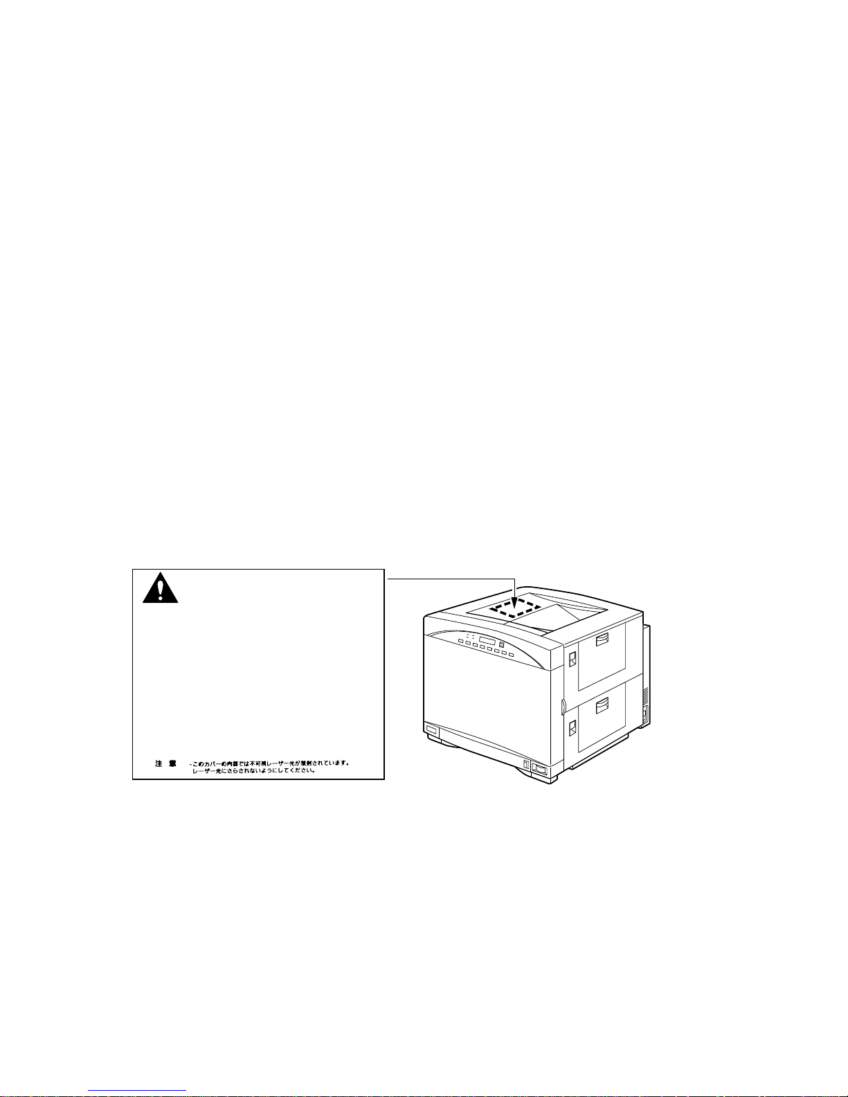
Class 1 Laser Product (100-120V/220-240V models)
Laser radiation could be hazardous to the human body . For this reason, laser radiation emitted inside this printer is hermetically sealed
within the protective housing and external cover. In the normal operation of the product by the user, no radiation can leak from the
machine.
This printer is certified as Class 1 laser product under the U.S. Department of Health and Human Services (DHHS) Radiation
Performance Standard according to the Radiation Control for Health and Safety Act of 1968. (This means that the printer does not
emit hazardous laser radiation.)
The label shown below is attached to this printer.
ATTENTION -
VORSICHT -
ATTENZIONE -
PRECAUTION-
VARO! -
VARNING! -
ADVARSEL! -
ADVARSEL -
WARNING:
DANGER -
CAUTION -
When servicing the machine or laser module, follow the procedures specified in the manual so that there are no hazards
Invisible laser radiation when open.
AVOID DIRECT EXPOSURE TO BEAM.
INVISIBLE LASER RADIATION WHEN OPEN.
AVOID EXPOSURE TO BEAM.
RAYONNEMENT LASER INVISIBLE EN CAS D'OUVERTURE.
EXPOSITION DANGEREUSE AU FAISCEAU.
UNSICHTBARE LASERSTRAHLUNG, WENN ABDECKUNG GEÖFNET.
NICHT DEM STRAHL AUSSETZEN.
RADIAZIONE LASER INVISIBLE IN CASO DI APERTURA.
EVITARE L'ESPOSIZIONE AL FASCIO.
RADICION LASER INVISIBLE CUANDO SE ABRE.
EVITAR EXPONERSE AL RAYO.
AAVATTAESSA OLET ALTTIINA NÄKYMÄTTÖMÄLLE
LASERSÄTEILYLLE. ÄLÄ KATSO SÄTEESEEN.
OSYNLIG LASERSTRÅLNING NÄR DENNA DEL ÄR ÖPPNAD.
BETRAKTA EJ STRÅLEN.
USYNLIG LASER STRÅLING, NÄR DENNE ER ÅBEN.
UNDGÅ BESTRÅLING.
USYNLIG LASERSTRÅLING, NÄR DEKSEL ÅPNES.
UNNGÅ EKSPONERING FOR STRÅLEN.
RS5-8169
from the laser. The use of controls, adjustments, or performance of procedures other than those specified in this manual may result in
hazardous laser radiation exposure.
WARNING:
The label shown above is intended as a warning to persons disassembling the Raster Laser Scanner unit for internal
alignment or repair purposes. It does not apply to any of the maintenance procedures specified in this manual.
CDRH Regulations
The Center for Devices and Radiological Health (CDRH) of the U.S. Food and Drug Administration implemented regulations for
laser products on August 1, 1976. These regulations apply to laser products marketed in the United States. The label on the printer
indicates compliance with the CDRH regulations and must be attached to laser products marketed in the United States.

Contents 1
Preface
About the illustrations in this guide xiii
Terminology and conventions xiv
Important safety information xiv
Handling the printer xv
Choosing a location for the Colorwriter xv
Unpacking and setting up the Colorwriter xvi
Operating the Colorwriter xvii
Network precautions xviii
Protecting the LCD display xviii
Ozone emission xviii
Laser safety xix
Toner safety xx
Chapter 1: Introduction
How the Colorwriter operates 1-2
Parts of the printer 1-5
Print options 1-7
Client utility software 1-7
Chapter 2: Using the Control Panels
Using the density control panel 2-1
Density adjustment 2-2
Test patterns 2-3
Separation voltage control designation 2-5
Edge registration 2-6
Using the printer control panel 2-7
Activity lights 2-8
Display window 2-8
Buttons 2-8
Error messages 2-9
Menu options 2-10
Chapter 3: Operation
Overall control system 3-3
Main PCBs 3-5
Drive system 3-12
Basic sequence of operation 3-14
Laser/scanner system 3-16
Video data processing 3-17
Laser control circuit 3-19
Scanner system 3-23
vii

Table of Contents
Image formation system 3-25
Image formation configuration 3-28
Print process 3-32
High-voltage control 3-45
Photosensitive drum life detection 3-54
Developing unit control 3-58
Image quality stability control 3-69
Pick-up/Feed System 3-74
Paper pick-up 3-76
Transfer drum and peripheral components 3-86
Fixing and delivery unit 3-95
Oil circulation system 3-107
Fixing unit motor drive circuit 3-111
Paper jam detection 3-112
System interface 3-119
Video interface 3-120
Power supply 3-121
Remote switch 3-123
Protection function 3-123
Paper feeder 3-124
Electrical circuit 3-124
Paper feeder driver input/output 3-125
Pick-up/feed system 3-126
Chapter 4: Installation Overview
Removing printer shipping materials 4-1
Installing the photosensitive drum 4-2
Installing the waste toner bottle 4-5
Installing the toner cartridges 4-7
Installing the silicone oil bottle 4-11
Attaching the optional paper feeder unit 4-13
Checking the package contents 4-13
Chapter 5: Service Procedures
Servicing the Colorwriter 5-1
Software service 5-1
Accessing Colorwriter’s internal components 5-2
To shut down the Colorwriter 5-2
Removing covers and panels 5-3
Exhaust Fan 5-19
viii

Table of Contents
Drive System 5-25
Fixing unit motor 5-25
Developing unit motor 5-26
Drum motor 5-27
Drive unit 5-28
Rotary manual unit 5-30
Transfer drum cleaner press drive unit 5-32
Discharge roller press drive unit 5-33
Drum press drive unit 5-34
Attraction roller press drive unit 5-35
Delivery drive unit 5-36
Paper transport system 5-37
Pick-up unit 5-37
Separating the manual feeding tray pick-up unit
from the cassette pick-up unit 5-39
Manual feed solenoid 5-42
Manual feeding pick-up roller 5-43
Separation pad 5-44
Feed roller unit 2 5-46
Pick-up motor 5-48
Registration roller clutch 5-51
Registration upper/lower rollers 5-52
Cassette feed solenoid 5-55
Separation roller 5-56
Feed roller 1 5-57
Transfer Drum Holder Unit 5-58
Exposure system 5-78
Laser/scanner unit 5-78
Charging system 5-79
Drum cartridge 5-79
Density sensor unit 5-82
Developing system 5-84
Toner cartridge 5-84
Developing rotary unit 5-86
Fixing system 5-90
Fixing unit 5-90
Fixing Cleaning Unit 5-106
Fixing delivery unit 5-109
Oil applying unit 5-110
Bottle case unit 5-114
ix

Table of Contents
Electrical components 5-119
Video controller PCB 5-119
DC controller PCB 5-127
Mechanical controller PCB 5-131
Pick-up PCB 5-132
Terminal PCB 5-133
Cassette-size sensing PCB 5-134
Waste Toner Sensor PCB 5-137
Toner-low detect beam PCB 5-139
Toner-low Detect Receive PCB 5-139
Power Supply 5-140
High-voltage Power Supply 5-143
Separation HVT PCB 5-144
Temperature/humidity sensor 5-145
Oil overflow sensor 5-147
Oil sensor PCB 5-149
Ejection PCB 5-150
Paper Feeder 5-152
External paper feeder covers 5-153
Pick-up unit 5-157
Paper feeder PCB 5-164
Power Supply 5-166
Cassette-size sensing PCB 5-167
Installing system software 5-170
Installing system software 5-170
Chapter 6: Troubleshooting Procedures
Preliminary on-site checkout 6-1
Checking the cables 6-1
Checking the installation environment 6-2
Checking the print paper 6-2
Checking consumable materials 6-2
Checking the charging unit 6-2
Other 6-3
Checking for paper jams 6-3
Start-up diagnostics and error messages 6-7
Selecting video controller extended diagnostics 6-9
Basic troubleshooting procedures 6-12
How to read the troubleshooting procedure table 6-13
Printer Driver Tester (PDT) 6-14
Measurement and adjustment 6-16
Electrical system adjustments 6-18
Image Defects 6-22
Troubleshooting image defects 6-25
Troubleshooting malfunctions 6-38
Paper Transport Troubleshooting 6-59
Paper Jams 6-59
Incomplete Paper Feed 6-64
x

Table of Contents
Locations/roles of electrical parts 6-66
Switches 6-66
Sensors 6-68
Clutches/Solenoids 6-71
Motors 6-73
PCBs 6-75
Connectors 6-77
Variable Resistors (VR), LEDs, Test Pins, Jumpers,
and Switches on PCB 6-80
DC controller PCB 6-80
Video controller PCB 6-81
Mechanical controller PCB 6-82
High-voltage power supply PCB 6-83
Separation HVT PCB 6-84
Ejection sensing PCB 6-84
Cassette size-sensing PCB 6-85
Paper feeder driver PCB 6-86
Checking network connections 6-87
Appendix A: Specifications
Hardware features A-1
Networking and connectivity A-1
Style A-2
Options A-2
Supplies A-3
Paper A-3
Feeder A-3
Types A-3
Handling A-4
Fonts A-5
Functions A-5
Additional functions A-5
Product life A-6
Environmental A-6
EMC standards A-8
Immunity A-8
Momentary interruption of power A-8
AC line noise A-9
Surge voltage A-9
Packaging A-9
Vibration A-9
Shock A-10
xi

Table of Contents
Safety approvals A-10
AC input power specifications: LNC01-A2 A-11
AC input power specifications: LNC01-A3 A-12
Remote utility software A-14
Maintenance by serviceperson A-14
Appendix B: Maintenance Requirements
Service maintenance B-1
60K service maintenance B-2
Service checkpoints B-5
Customer maintenance/checks B-6
Metrics B-12
Usage model B-12
Paper feed reliability B-12
Tools you will need B-13
Special tools B-14
List of Lubricants, Cleaners B-15
Appendix C: Moving the printer
Appendix D: Spare Parts
Appendix E: Accessories and Supplies
Optional paper feeder unit E-1
Memory upgrade kits E-2
Ordering consumables E-2
Toner cartridges E-2
Silicone oil E-3
Drum cartridge kit E-4
Transparency film E-5
Paper E-5
Appendix F: Related Documentation
Technical support F-2
Electronic orders F-2
Telephone and direct mail orders F-3
Index
xii

Preface
The Colorwriter LSR 2000 Printer Service Guide is intended for
certified printer technicians installing or servicing a Colorwriter
LSR 2000. If you have not received installation and service
certification, you should not attempt to service the Colorwriter.
This guide is divided into the following sections:
• “Preface ” gives general information about this guide and general
information that you should know before you attempt to install
a Colorwriter.
• Chapter 1, “Introduction”, provides general information about
the Colorwriter.
• Chapter 2, “Using the Control P anels ”, pr ovides o verview of the
Colorwriter Control Panel and the Density Control Panel.
• Chapter 3, “Operation”, provides detailed information on how
the printer functions.
• Chapter 4, “Service Procedures”, describes removal and
replacement procedures for Colorwriter components.
• Chapter 5, “Troubleshooting Procedures”, identifies the source
of common problems that may occur with the printer and
suggests ways of correcting them.
Colorwriter customers should not use the technical service
documentation. Please don’t leave your copy of the
2000 Printer Service Guide
behind after you make a service call.
Colorwriter LSR
About the illustrations in this guide
The illustrations in this guide reflect the version of the Colorwriter
at the time of publication. Components shown in these illustrations
are subject to change. To receive information about any Colorwriter
components that do not match illustrations in this guide, contact
your authorized service/support center.
xiii

Colorwriter LSR 2000 Printer
Service Guide
Preface
Terminology and conventions
The term network administrator refers to the person responsible for
maintaining the network at the customer site.
The term
in the Colorwriter printer control panel.
The term
front of the Colorwriter that includes the activity lights, display
window, and the buttons below the display window.
The
that allows you to change color density, print test patterns, adjust
separation voltage control designation and to adjust edge
registration.
The term
computer capable of running MS-DOS
display window refers to the LCD (liquid crystal display)
printer control panel is used to describe the area on the
density control panel describes the area on the back of the printer
PC-compatible refers to any IBM PC-compatible
version 5.0 or later.
The term PC-based server refers to any device that may be connected
to the Colorwriter for parallel printing.
The arrow highlights important notes and additional information.
!
The caution icon indicates a need for special care and safety when
handling the equipment.
Important safety information
This printer is a high-precision electronic device. Be sure to read
these safety instructions fully before you begin.
Follow all warnings and instructions marked on the printer and
consumables, such as the toner cartridges and silicone oil bottles.
xiv
Service Guide
PrefaceColorwriter LSR 2000 Printer
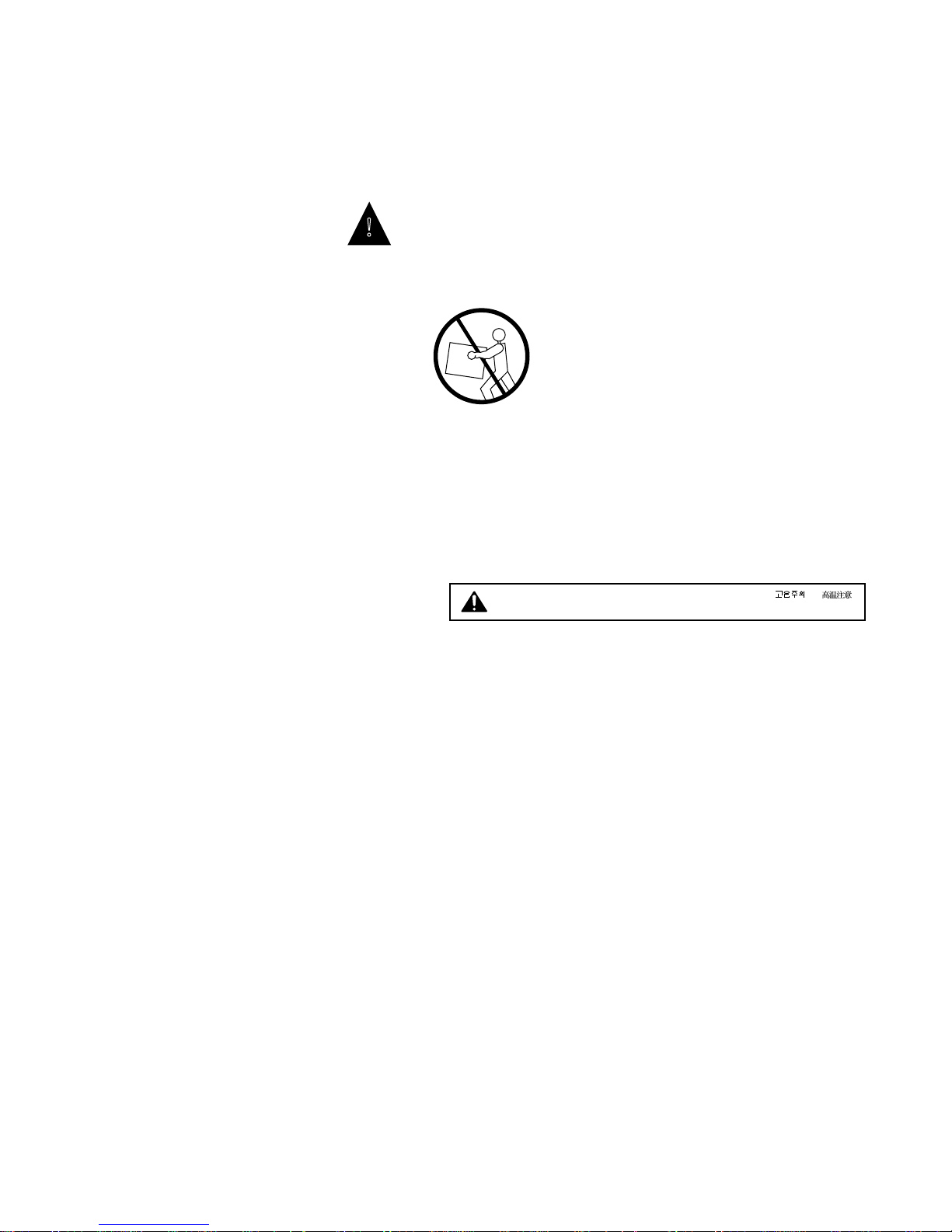
Handling the printer
!
printer alone weighs approximately 110 lb (50 kg). It should always
be moved by two or more people. Do not attempt to move it by
yourself.
• When installing the printer, carefully observe the location
requirement described in this manual.
• Never place the printer near or over a radiator, heat emitter, or
flame.
• When the printer is in use, the fixing assembly and delivery
areas become extremely hot. Be careful not to touch these areas.
Do not place this printer on an unstable cart, stand, or table. The
CAUTION! HOT SURFACE. AVOID CONTACT ACHTUNG HEISS
ATTENTION! TEMPERATURE ELEVEE PRECAUTION! / ATTENZIONE! ALTA TEMPERATURA
• When moving the printer, be sure to turn the power off before
unplugging the power cable.
• Handle all PCBs (printed circuit boards) by their edges only, but
avoid touching the contacts on the edge of the board.
Choosing a location for the Colorwriter
• Do not expose the printer to a wet environment.
• Do not directly expose the printer to a chemical environment,
for example, an experimental laboratory. The exterior of the
printer is made of plastic, and the outside covering may fade,
become deformed, or melt.
• Do not install the printer where it is exposed to smoke or steam
or sun.
• The printer should never be placed near or over a radiator or
heat register. This printer should not be placed in a built-in
installation unless proper ventilation is provided.
xv

Colorwriter LSR 2000 Printer
Service Guide
Preface
Unpacking and setting up the Colorwriter
• Report any shipping damage. If there is any evidence of
shipping or handling damage to the Colorwriter packing boxes
or their contents, save the damaged boxes and parts, call the
shipper immediately to file a claim, and notify your authorized
service/support center.
• Do not operate the printer until all packaging materials
(packing tape, spacers, and styrofoam molds) have been
removed.
• Before connecting the printer to a power source, check the
voltage rating label at the back of the printer to ensure that the
printer voltage matches that of the power source. The voltage
rating label is located on the rear of the printer. If the voltage
label is missing, contact the nearest authorized dealer or your
place of purchase.
• Be sure to unravel the power cord prior to plugging it in. Using
it tied up may lead to damage, overheating, a short-circuit, or
fire.
• Be sure to plug the power cord well into the po wer outlet, as any
flammable material caught between an opening may result in
fire.
• Avoid using an extension cord. If it is unavoidable, be sure to
take the following precautions. Failure to do this may lead to
overheating, fire, or cause flickering due to a drop in voltage.
• Be sure not to exceed the allowed rating current of the
extension cord. Make sure that the total ampere rating of the
products plugged into the extension cord does not exceed
the extension cord ampere rating.
• Use a short extension cord. Do not connect several extension
cords together.
• Be sure to connect the printer to a ground terminal.
• The power cord should be routed so that it is not likely to be
walked on or pinched by items placed on or against it. Pay
particular attention to the plug, the receptacle, and the point
where the cord exits the unit.
xvi
• When connecting cables or disconnecting cables from the
printer, make sure that the power switch is in the off position.
• Keep the power cord and cables away from children.
• Do not handle plugs with wet hands.
Service Guide
PrefaceColorwriter LSR 2000 Printer
• Be sure to turn off the power before unplugging or plugging in
the printer power cord or interface cable.
• Be sure to use a surge suppressor on the Colorwriter.
Operating the Colorwriter
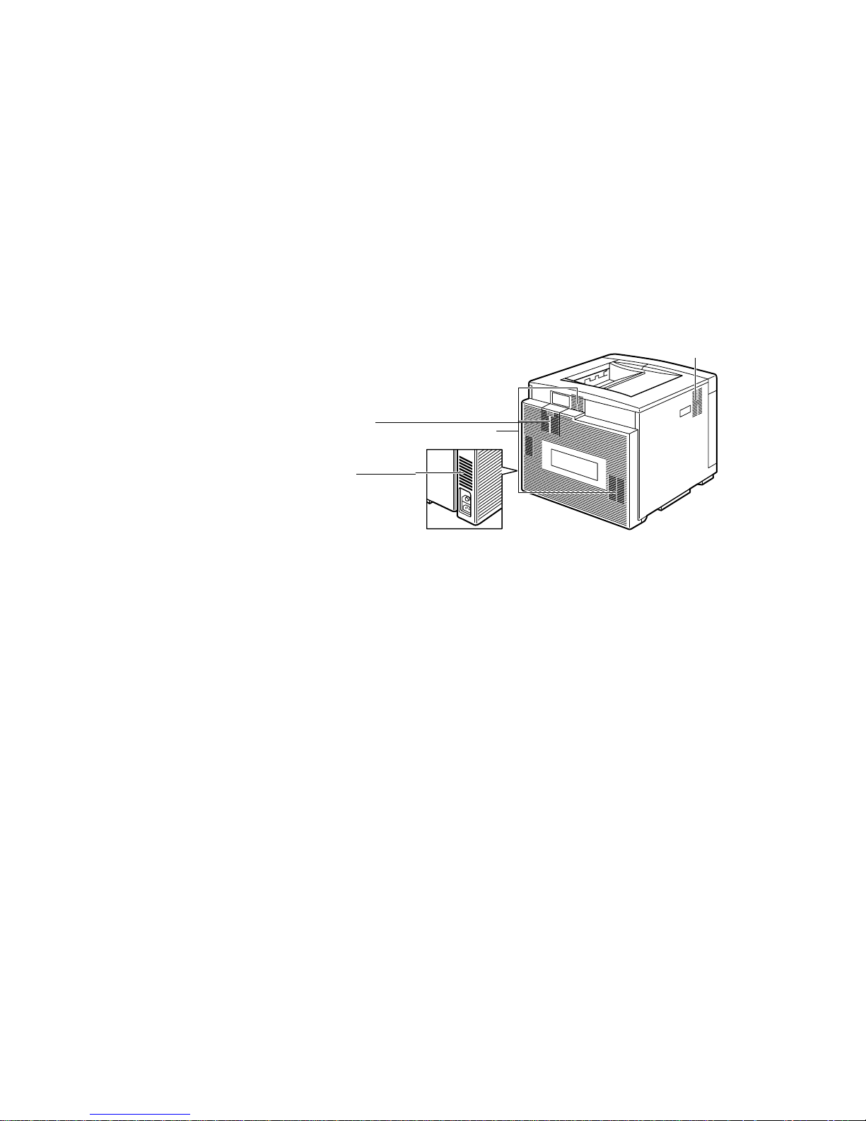
• Slots and openings in the cabinet are provided for ventilation.
To ensure reliable operation of the printer and protect it from
overheating, these openings should never be blocked or covered.
Air ventilation slots
Inhalation slot
• The printer is equipped with a 3-wire grounding type plug,
which has a third (grounding) pin. This plug will fit only into a
grounding-type power outlet. If you are unable to insert the
plug into the outlet, contact your electrician to replace your
obsolete outlet. Do not defeat the purpose of the groundingtype plug.
• If the printer will not be used for a long period of time, turn the
power off and unplug the power cord.
• Unplug the printer from the wall outlet before cleaning. Use a
damp cloth for cleaning. Do not spray liquid cleaners or aerosol
cleaners directly on the cabinet or the openings, as the spray
could penetrate inside the printer and contaminate internal
parts.
• Never push objects of any kind into the printer through
openings in the enclosure, as the objects may touch dangerous
voltage points or short out parts. This could cause a fire or
electrical shock.
• Never spill any liquids into the printer.
• The outlet should always be free from any obstacles so as to
allow easy access.
• When unplugging the printer, always disconnect the po wer cord
by pulling on the plug, not the cord itself.
xvii

Colorwriter LSR 2000 Printer
Service Guide
Preface
• Any misuse of electrical equipment is hazardous. Do not allow
children to handle power cords or cables.
• Avoid operating the printer when the waste toner bottle and/or
silicone oil bottle is not installed; otherwise the printer may be
damaged.
• Do not attempt to modify the printer.
• Do not remove the warning or instruction labels on the printer.
• Do not dispose of the used waste toner box or the silicone oil
box into a fire.
Network precautions
• Never alter an existing network without permission from the
network administrator. The Colorwriter will probably be
connected to an existing Local Area Network (LAN) based on
Ethernet
customer’s computer other equipment. Never disturb the LAN
by breaking or making a network connection, altering
termination, installing or removing networking hardware or
software, or shutting down networked devices without the
knowledge and express permission of the system or network
administrator or the shop supervisor.
hardware. The network is the link between the
• Never enter an IP address in Colorwriter Network Setup. Only
the network administrator should enter an IP address on a
network device. Assigning a Colorwriter an incorrect IP address
can cause unpredictable errors on any or all devices connected to
the network.
Protecting the LCD display
The Colorwriter has a liquid crystal display (LCD) that is made of
glass and can break. Do not subject the Colorwriter to strong
shocks.
If the display window breaks and the liquid crystal material leaks
out, do not inhale, ingest, or touch it. If the material gets on your
skin or clothing, wash it off with soap and water immediately.
Ozone emission
This printer meets the requirements for ozone emission of the
applicable standard published by Underwriters’ Laboratories, Inc.
(UL). Ozone (O
) is a colorless gas by-product of the
3
xviii
Service Guide
PrefaceColorwriter LSR 2000 Printer
electrophotographic process. Ozone is discharged only while the
printer is printing, and is emitted through the exhaust port on the
rear, left side of the printer.
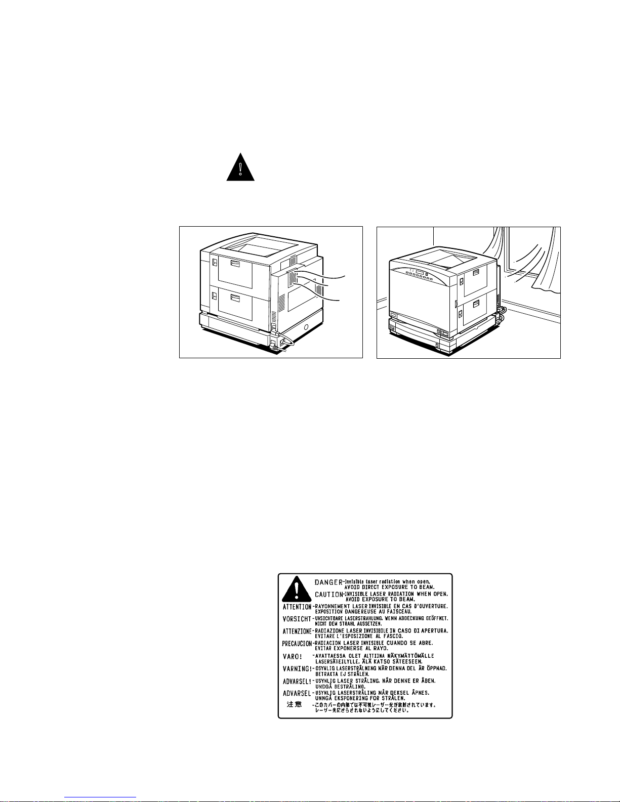
!
Those who are particularly sensitive to ozone odor may rarely feel
sick if exposed to it excessively. To avoid this, make sure that the
following measures are taken.
• Install the printer in a well ventilated room.
O
3
• Avoid using multiple laser printers simultaneously.
• Avoid facing the exhaust port directly toward users.
• Replace a disposable ozone filter after about 60,000 prints.
• Avoid using the printer without a filter.
Laser safety
An invisible laser beam is radiated in the laser/scanner unit and
could be hazardous to the human body if exposed to it. For this
reason you should not disassemble the laser/scanner unit and it
should not be adjusted in the field. The following warning is
attached to the cover of the laser/scanner unit.
xix

Colorwriter LSR 2000 Printer
Service Guide
Preface
Toner safety
Toner is a harmless substance. If you get toner on your skin or
clothes, remove as much as possible with a dry tissue and then wash
it with cold water. Do not use hot water; the toner may gel and
become hard to remove. Toner easily decomposes vinyl material;
therefore you should not let it come into contact with this material.
xx

Chapter 1:
Introduction 1
The Colorwriter LSR 2000 printer is a full-color laser beam printer
based on the standard CMYK (cyan, magenta, yellow, and black)
color model. The Colorwriter has the following features:
• Toner cartridges separate from photosensitive drum
The four color toner cartridges (cyan, magenta, yellow, and
black) are installed separately from the photosensitive drum.
When a toner cartridge is used up, just replace the toner
cartridge with a new one of the same color.
• Flexible color range
The four color toner cartridges offer output in full color, a single
color only (monocolor), or the traditional true black (using the
black toner cartridge).
• High resolution
The 600-dpi resolution gives you crisp, clean, and laser sharp
output in full color.
• High print speed
The printer prints at 3 letter-sized pages per minute in full color ,
or 12 letter-sized pages per minute in monocolor (using one of
the toner cartridges). Overhead transparencies are printed at 1
page per minute.
• Flexible paper handling
The supplied paper cassette preset (A4 or letter-size, depending
on the voltage package) can hold about 250 sheets (at 80 g/m2)
of plain paper. The multipurpose tray accepts transparency films
as well as plain paper. You can also purchase a universal paper
cassette which can hold various paper sizes—Letter, A4, B5, or
legal. For higher volume, the optional paper feeder unit can be
used.
1-1

Colorwriter LSR 2000 Printer
Service Guide
1: Introduction
The Colorwriter enables users of Macintosh
computers, PC-
compatibles, and UNIX workstations to:
• Send images over AppleTalk
through a parallel (Centronics
, TCP/IP, Nov ell
) port to print to the
networks, and
Colorwriter.
• Spool print jobs and select a printing priority for each job. U sers
can also control spooled print jobs sent to the Colorwriter with
remote utility software running on networked Macintosh and
PC-compatible computers.
• Print PostScript and EPS files in color and grayscale.
• Use 39 resident fonts. The customer can download additional
PostScript Type 1 or Type 3 fonts as needed.
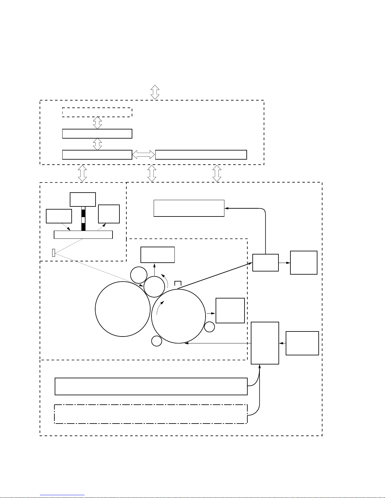
How the Colorwriter operates
The basic operation of the Colorwriter can be divided into four
blocks: the overall control system, the laser/scanner system, the
image formation system, and the pick-up/feed system.
• Overall control system—is controlled by the video controller
PCB, terminal PCB, DC controller PCB and the mechanical
controller PCB. When the video controller board receives a
print command from an external networked device, the
command is sent to the DC controller and the mechanical
controller which begins the printing process. These boards
control the engines that perform the printing process.
• Laser/Scanner system—once printing has begun the DC
controller begins to stabilize the intensity of the laser beam. The
laser beam strikes the scanning mirror which rotates at a
constant speed. The laser beam reflected b y the scanning mirror
focuses on the photosensitive drum after passing through the
focusing lens and being reflected by the reflection mirror. When
the scanning mirror rotates at a constant speed, the laser beam
scans at an even speed across the photosensitive drum. A latent
image is formed on the photosensitive drum as it is also rotating
at a steady speed.
• Image formation system—is made up of the photosensitive
drum, transfer drum, developing unit, primary charging roller,
and other components. The primary charging roller negatively
charges the entire surface of the photosensitive drum while the
laser beam is radiated onto the surface of the photosensitive
drum. The latent image formed across the photosensitive drum
is made visible by the toner, and is transferred to the paper on
1-2

Service Guide
1: IntroductionColorwriter LSR 2000 Printer
the transfer drum. These steps are taken for each color. The
paper is rotated on the transfer drum until the color transfer
process is completed.
The paper is then separated from the transfer drum and
delivered to the fixing unit. The surface of the photosensitive
drum is cleaned with the cleaner blade for removal of remaining
toner, and the drum potential is kept uniform by the primary
charging roller in preparation for forming a new latent image.
The transfer drum surface is cleaned with the cleaning brush for
removal of remaining toner and the discharge roller remo ves the
surface charge.
This printer is also equipped with toner cartridge installation
detection, toner-low detection, toner stirring, and
photosensitive drum life detection functions.
Note:
The cleaning brush is activated after 100 prints.
• Pick-up/Feed system—When a print job is sent to the printer a
sheet of paper is picked up by either the cassette or manual
feeding pick-up roller, fed by the feed rollers. Any skew in the
paper is corrected by the registration roller, and then the paper
stops at the leading edge detection position. The temporarily
stopped paper is fed so that its leading edge will match the
gripper on the transfer drum as well as the leading edge of the
image on the photosensitive drum. Subsequently, the paper
passes through the transfer , separation, fixing, and delivery units
to the face-down or face-up tray.
1-3
Colorwriter LSR 2000 Printer
Service Guide
Video controller PCB
Terminal PCB
LASER/SCANNER SYSTEM
Scanner
motor
Laser
diode
Beam
position
detector
1: Introduction
To external device (computer, etc.)
OVERALL CONTROL SYSTEM
Mechanical controller PCBDC controller PCB
PAPER PICK-UP/FEED SYSTEM
Face-down tray
Scanning mirror
Primary
charging
roller
Developing
unit
IMAGE FORMATION SYSTEM
Cleaning
unit
Separation
charging unit
Photo-
sensitive
drum
Transfer drum
Attraction roller
Cassette
Paper feeder (optional)
Transfer
drum
cleaning
unit
Discharge roller
Fixing
unit
Pick-up
control
unit
Face-up
delivery
tray
Manual
feeding tray
1-4
Figure 1-1 Colorwriter functional diagram
Service Guide
1: IntroductionColorwriter LSR 2000 Printer
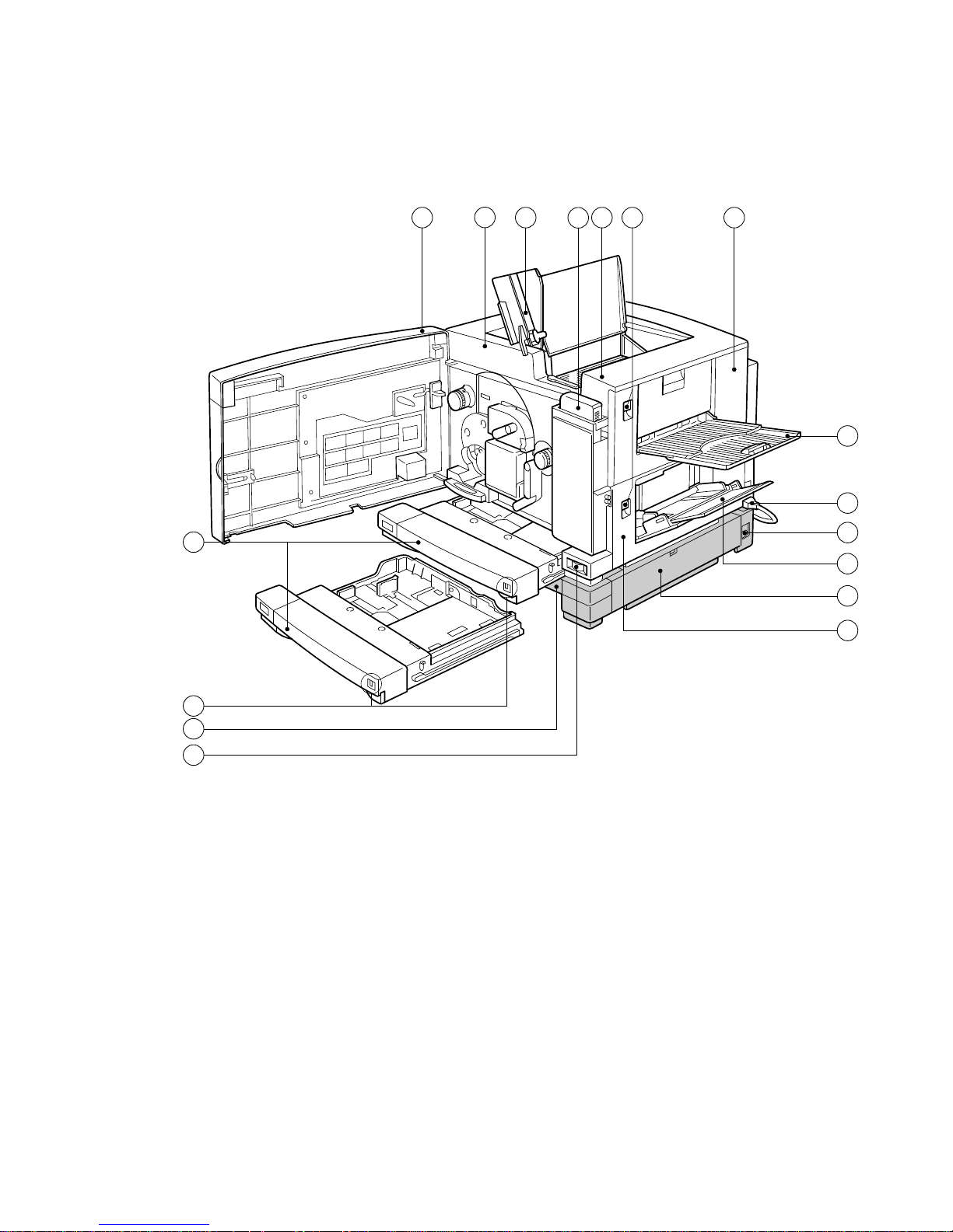
Parts of the printer
14
15
16
17
2 3 4
1
5
6
7
8
9
10
13
12
11
1—Oil bottle
2—Upper cover
3—Release knob
4—Fixing unit cover
5—Face-up tray
6—Power cable
7—Power receptacle
8—Manual feeding tray
Figure 1-2 Printer — external view
9—Paper feeder (right door)
10—Pick-up cover
11—Power switch
12—Paper feeder
13—Paper capacity indicator
14—Cassette
15—Front door
16—Printer Control Panel
17—Face-down tray
1-5
Colorwriter LSR 2000 Printer
Service Guide
1: Introduction
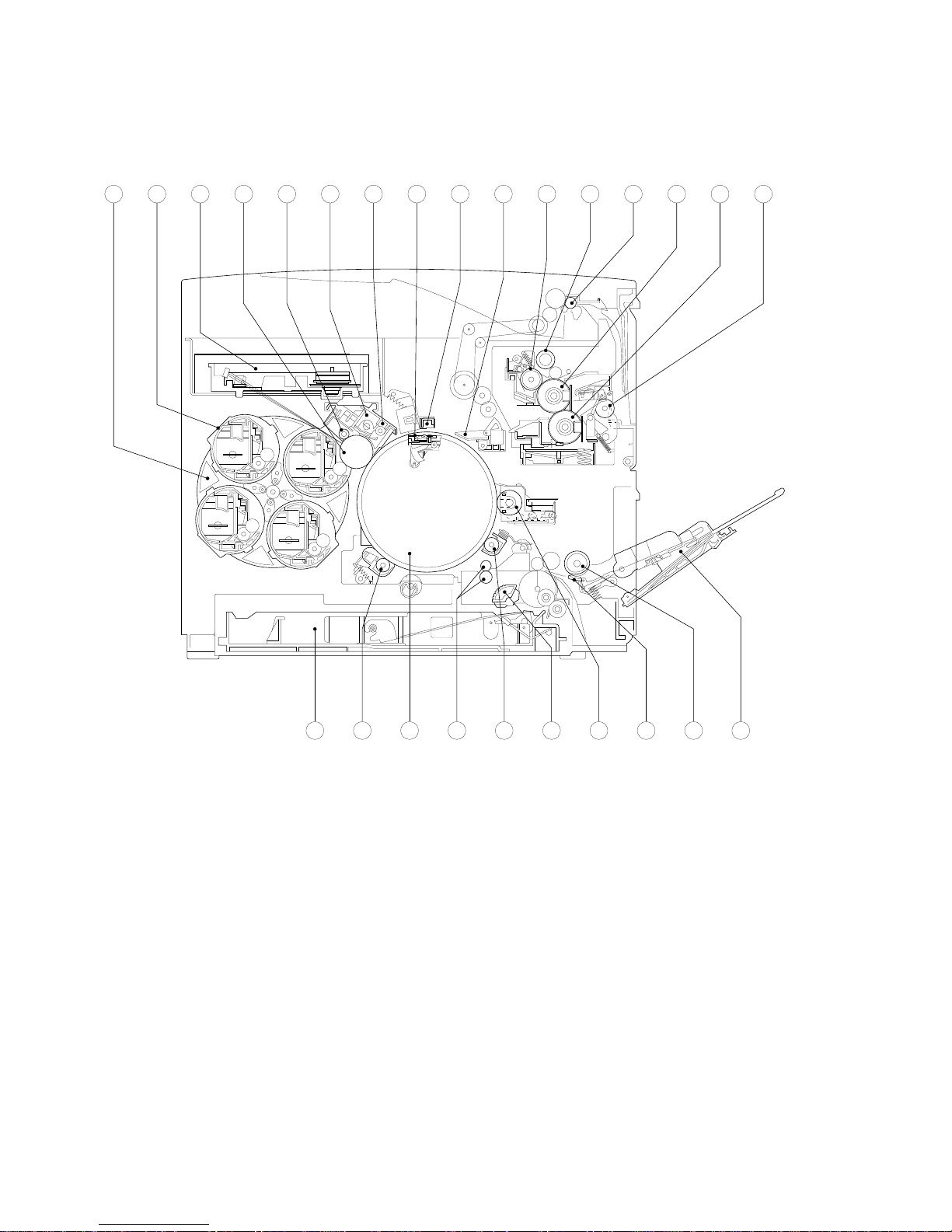
16151413121110987654321
1-6
1—Developing rotary unit
2—Toner cartridge
3—Laser/scanner unit
4—Photosensitive drum
5—Primary charging roller
6—Drum cartridge
7—Cleaning unit
8—Gripper
2223242526
9—Separation charging unit
10—Separation claw
11—Oil applying roller
12—Cleaning belt
13—Face-down delivery roller
14—Fixing upper roller
15—Fixing lower roller
16—Fixing delivery roller
17—Manual feeding tray
21 20 19 18 17
18—Manual feeding pick-up roller
19—Separation pad
20—Cleaning brush
21—Cassette pick-up roller
22—Discharge roller
23—Registration rollers
24—Transfer drum
25—Attraction roller
26—Cassette
Figure 1-3 Printer — cross sectional view

Service Guide
1: IntroductionColorwriter LSR 2000 Printer
Print options
The Colorwriter’ s efficient P ostScript capabilities allow customers to
use a variety of applications to create printed pages with text,
images, or a combination of text and images, and print them in
Contone or Halftone mode. The Colorwriter operates over a
network or by printing directly to the Colorwriter’s parallel port.
RIP-While-Print
processing the next image.
The Colorwriter offers an efficient way to print files that have been
saved in PostScript or EPS (Encapsulated PostScript) format. These
files can be downloaded directly to the Colorwriter using the
Fiery XJ Downloader, one of the remote utilities provided with
Colorwriter.
allows the printer to print an image while
With the parallel port option, customers can print documents
directly from applications running on a PC-compatible computer or
a server that is connected to the Colorwriter’s parallel port.
PostScript files can also be printed to the parallel port from the
DOS prompt or the Windows File Manager.
Client utility software
Colorwriter users who are working with Macintosh and
PC-compatible computers using AppleTalk can download fonts and
flies, scan color images, and control spooled print jobs using client
software delivered with the Colorwriter. The network administrator
at the customer site is responsible for loading software onto
computers that will use the Colorwriter over the network.
The Colorwriter user software floppy disks (for Macintosh or PCcompatible computers) contain the following software:
• The Fiery XJ Downloader
download PostScript or EPS files directly to the Colorwriter
without opening the file or the application that created the file.
The Fiery XJ Downloader also allows the customer to manage
the printer fonts installed on the Colorwriter’s hard disk.
is a utility that allows the user to
• The Fiery XJ Spooler
is a utility that allows a user to control
Colorwriter print jobs from a networked Macintosh or PC
computer. It allows the user to view the order and priority of
jobs, delete jobs, and move jobs between queues.
• A set of Adobe Macintosh screen fonts that correspond to the
PostScript printer fonts resident on the Colorwriter.
1-7

Colorwriter LSR 2000 Printer
Service Guide
1: Introduction
• Printer description files that allow remote users to access
PostScript Level 2 features when printing.
• Printer drivers for Macintosh and Windows that allow
applications to communicate with the Colorwriter and use all
the PostScript Level 2 printing features of the Colorwriter.
• Color reference pages allow users to print CMYK and
PANTONE color swatches to view the range of colors available
on the Colorwriter.
The CD-ROM contains the Fiery Print Calibrator
, printer
calibration software that runs on the Macintosh. The CD includes
an online user guide for the Fiery Print Calibrator, and Adobe
Acrobat Reader software for viewing and printing the user guide.
Instructions for installing the Fiery Print Calibrator and Acrobat
Reader are included in the accompanying booklet.
1-8
Chapter 2:
Using the Control Panels 2
The Colorwriter has two control panels: the density control panel
and the printer control panel. The density control panel on the back
of the printer can be used to change color density settings, change
test pattern pages, adjust separation voltage control designation, and
to adjust edge registration. The printer contr ol panel on the front of
the printer allows you to set options and view information about
print jobs and display status information about the printer.
Using the density control panel
This section describes the density control panel on the back of the
printer. Once the printer is installed and powers up correctly, you
can use the density control panel to change color density settings,
test pattern pages, and separation voltage control designation, or to
adjust edge registration.
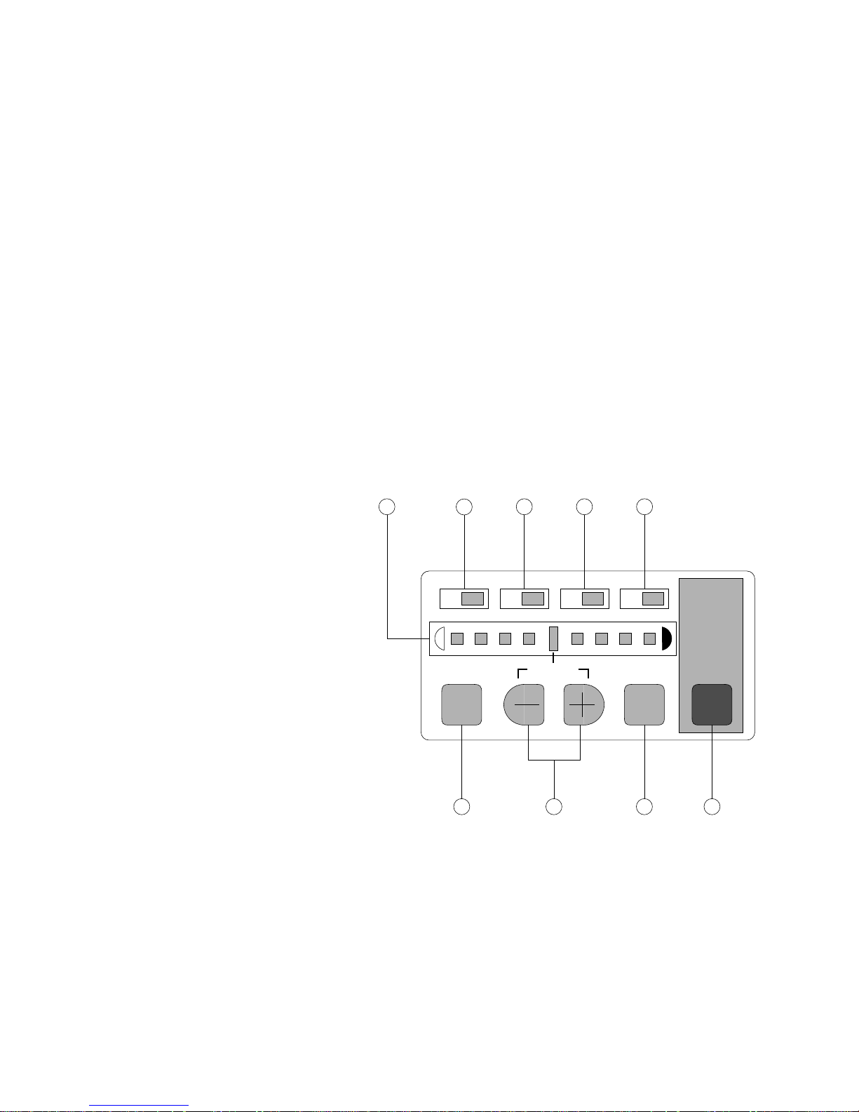
5
6
M C Y Bk
COLOR
SELECT
4 3 2 1
1—TEST PRINT key
2—ENTER key
3— +/- key
4—COLOR SELECT key
5—Density gauge
DEFAULT ENTER
987
TEST
PRINT
COLOR SELECT indicators:
6—M LED
7—C LED
8—Y LED
9—Bk LED
Figure 2-1 Density control panel
2-1
Colorwriter LSR 2000 Printer
Service Guide
2: Using the Control Panels
•
TEST PRINT
—Prints one of the available test patterns (solid color,
solid white, gradation, horizontal lines, vertical lines, or grid)
and allows you to check the results of a density change.
•
—After you select a new density for one of the color select
ENTER
indicators (M, C, Y, Bk), press this key to save the new density
for the selected color indicator.
—Use these keys to change the density or to select a new test
•
+/-
pattern for the
COLOR SELECT
•
TEST PRINT
—Press this key to select one of the color select
function.
indicators (M, C, Y, Bk) in order to change the density.
•
Density gauge
—Indicates the currently selected color density or
test print pattern.
•
—The color indicator lights when Magenta has been selected.
M
•
—The color indicator lights when Cyan has been selected.
C
•
—The color indicator lights when Yellow has been selected.
Y
•
— The color indicator lights when Black has been selected.
Bk
Density adjustment
Use the following procedure to customize the color density for
printed pages. Note that you can change the color density while
your job is busy printing.
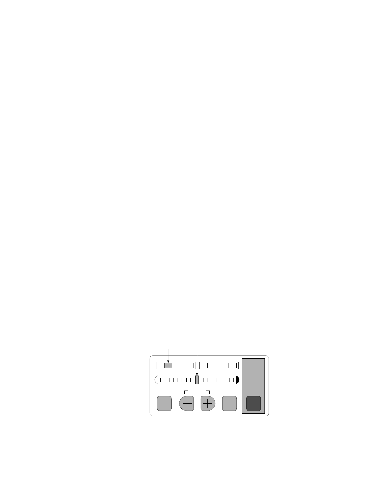
To adjust color density
1. Press the COLOR SELECT key to select a color to change.
The LED lights up indicating the selected color and density (see
Figure 2-2 below).
Selected color Density
M C Y Bk
COLOR
SELECT
DEFAULT ENTER
TEST
PRINT
2-2
Figure 2-2 Color density mode
 Loading...