

Digital Equipment ChannelWorks DECTV-AA, ChannelWorks DECTV-AB Installer's Manual

ChannelWorks
Cable TV Installer’s Guide
Part Number: EK-DECTV-IG. B01

Federal Communications Commission (FCC)
Radio Frequency Interference Statement
The following statement applies only to the ChannelWorks bridge:
This equipment generates, uses, and may emit radio frequency energy. The equipment
has been type tested and found to comply with the limits for a Class A digital device
pursuant to Part 15 of FCC rules, which are deigned to provide reasonable protection
against such radio frequency interference.
Any changes or modification to this equipment may void the user’s authority to operate
this equipment.
Operation of this equipment in a residential area may cause interference in which case
the user at his own expense will be required to take whatever measures may be required
to correct the interference.

ChannelWorks
Cable TV Installer’s Guide
February 1994
This manual, in conjunction with the
Installer’s Guide
describes how to install the ChannelWorks bridge. This manual
is intended for the hardware installer and network manager.
Supersession/Update Information: This is a revised manual.
Operating System and Version: LCB Revision 2.0
Management Utilities Version: LCC Revision 2.0
and the
ChannelWorks Management
ChannelWorks Network
manual,
Part Number: EK-DECTV-IG. B01

EK-DECTV-IG. B01
February 1994
The information in this document is subject to change without notice and should not be construed
as a commitment by Digital Equipment Corporation. Digital Equipment Corporation assumes no
responsibility for any errors that may appear in this document.
© Digital Equipment Corporation 1994. All rights reserved.
Restricted Rights: Use, duplication, or disclosure by the U. S. Government is subject to restrictions as set forth in subparagraph (c) (1) (ii) of DFARS 252.227-7013, or in F AR 52.227-19, or in
FAR 52.227-14 Alt. III, as applicable.
Possession, use, or copying of the software described in this publication is authorized only pursuant to a valid written license from Digital or an authorized sublicensor.
No responsibility is assumed for the use or reliability of software on equipment that is not supplied by Digital or its affiliated companies.
Digital Equipment Corporation makes no representations that the use of its products in the manner described in this publication will not infringe on existing or future patent rights, nor do the
descriptions contained in this publication imply the granting of licenses to make, use, or sell
equipment or software in accordance with the description.
The following are trademarks of Digital Equipment Corporation: ChannelWorks, Digital, LAT,
The Digital Channel, DECnet, PATHWORKS, POLYCENTER, and the DIGITAL logo.
UniLINK and LANcity are registered trademarks of LANcity Corporation.
IBM, OS/2, and Personal Computer AT are registered trademarks of International Business
Machines Corporation.
Microsoft and MS-DOS are registered trademarks, and Windows is a trademark of Microsoft Corporation.
Procomm is a registered trademark of Datastorm Technologies.
SNMPc is a trademark of Castle Rock Computing.

EMC Class A Notices
Warning - This is a Class A product. In a domestic environment this product may
cause radio interference in which case the user may be required to take adequate measures.
Achtung - Diese ist ein Gerat Funkstorgrenzwertklasse A. In Wohnbereichen konnen
bei Betreib dieses Gerates Rundfunkstorungen auftreten, in welchen Fallen der
Benutzer fur entsprechende Gegenmassnahmen verantwortlich ist.
Attention - C’est un produit de Classe A. Dans un environnement domestique, ce produit risque de creer des interferences radioelectriques, il appartiendra alors a l’utilisateur de prendre les mesures specifiques appropriees.
Canadian Department of Communications Compliance Statement
The Canadian Department of Communications label identifies certain equipment. This
certification means that the equipment meets certain telecommunications network protective, operational, and safety requirements. The Department does not guarantee that
the equipment will operate to the user’s satisfaction.
Before installing this equipment, users should ensure that it is permissible to be connected to the facilities of the local telecommunications company. The equipment must
also be installed using an acceptable method of connection. In some cases, the company’s wiring associated with a single line individual service may be extended by
means of a certified connector assembly (telephone extension cord). The customer
should be aware that compliance with the above conditions may not prevent degradation of service in some situations.
Repairs to certified equipment should be made by an authorized Canadian maintenance
facility designated by the supplier. Any repairs or alterations made by the user to this
equipment, or equipment malfunctions, may give the telecommunications company
cause to request the user to disconnect the equipment.
User’s should ensure for their own protection that the electrical ground connections of
the power utility, telephone lines, and internal metallic water pipe system, if present,
are connected together. This precaution may be particularly important in rural areas.
Caution -
!
the appropriate electrical inspection authority, or electrician, as appropriate.
Users should not attempt to make such connections themselves, but should contact
v

Acoustics - Declared values per ISO 9296 and ISO 7779
Sound Power Level Sound Pressure Level
L
BL
WAd,
pAm,
dBA
(bystander positions)
Product Idle/Operate Idle/Operate
DECTV-AA 5.0 35
[Current values for specific configurations are available from Digital representatives.
1 B = 10 dBA.]
Schallemissionswerte - Werteangaben nach ISO 9296 und ISO 7779/DIN EN27779
Schalleistungspegel Schalldruckpegel
L
BL
WAd,
pAm,
dBA
(Zuschauerpositionen)
Produkt Leerlauf/Betrieb Leerlauf/Betrieb
DECTV-AB 5.0 35
[Aktuelle Werte f|r spezielle Ausr|stungsstufen sind |ber die Digital Equipment Vertretungen erhdltlich. 1 B = 10 dBA.]
Nippon - Japan
vi

Contents
Preface
1 Introduction
Introduction..................................................................................................................................1-1
Installation Tools And Equipment Required ..............................................................................1-2
Tools You Need.................................................................................................................... 1-2
Installation And Verification Equipment You Need............................................................1-2
Additional Installation Equipment You May Need..............................................................1-3
Physical Description .................................................................................................................... 1-3
Input/Output Connections..................................................................................................... 1-3
Ethernet Ports ................................................................................................................ 1-3
Ethernet Port Selection Switch...................................................................................... 1-5
Cable TV Ports..............................................................................................................1-5
Serial Port......................................................................................................................1-5
The ChannelWorks Bridge Identifying Symbols .................................................................1-6
10BaseT Link Status LED.............................................................................................1-6
Power On LED..............................................................................................................1-6
Ethernet Transmit LED ................................................................................................. 1-6
Ethernet Receive LED................................................................................................... 1-6
Broadband Transmit LED ............................................................................................. 1-6
Broadband Receive LED............................................................................................... 1-6
Status LED.....................................................................................................................1-6
Block Sync LED............................................................................................................1-7
Specifications............................................................................................................................... 1-8
Dimensions And Weight.......................................................................................................1-8
ChannelWorks Bridge...................................................................................................1-8
TransMaster................................................................................................................... 1-8
Power Requirements............................................................................................................. 1-8
ChannelWorks Bridge...................................................................................................1-8
TransMaster................................................................................................................... 1-8
Normal Operating Environment...........................................................................................1-9
ChannelWorks Bridge...................................................................................................1-9
TransMaster................................................................................................................... 1-9
RF Electrical Specifications .................................................................................................1-9
ChannelWorks Bridge...................................................................................................1-9
TransMaster................................................................................................................. 1-10
Cable TV Network Requirements.............................................................................................. 1-10
vii

Contents
2 Cable TV Network Overview
Introduction .................................................................................................................................2-1
Cable TV Network Topologies.................................................................................................... 2-1
Typical Metropolitan Area Network Over Cable TV...........................................................2-1
Single Cable Plants...............................................................................................................2-3
Dual Cable Plants .................................................................................................................2-3
Topologies ............................................................................................................................ 2-3
3 Preparing The Cable TV Network
Introduction .................................................................................................................................3-1
Setting Up The Headend Translator ............................................................................................3-1
Verifying And Setting Up Test Equipment .................................................................................3-1
Setting The TransMaster’s Forward And Return Frequencies.............................................3-2
Forward (Output) Channel Frequency Selection........................................................... 3-2
Return (Input) Channel Frequency Selection................................................................3-2
Verifying The TransMaster’s Output Signal Level..............................................................3-4
Adjusting The TransMaster Gain ......................................................................................... 3-4
Cable TV Cable Verification Tests..............................................................................................3-6
Verifying Selected Cable TV Drop’s Center Frequency Receive Level.............................. 3-7
Verifying The Flatness Of The Cable TV Network At The Selected Drop ......................... 3-8
Verifying The Cable TV Network’s Return Outlet To Outlet Variation............................3-10
4 Configuring And Installing The ChannelWorks Bridge
Introduction .................................................................................................................................4-1
Installing The LANcity Management Utility On A PC........................................................4-2
Setting Up User Accounts ....................................................................................................4-4
User Levels...........................................................................................................................4-6
Level One ...................................................................................................................... 4-6
Level Two...................................................................................................................... 4-6
Level Three.................................................................................................................... 4-6
Level Four .....................................................................................................................4-6
Setting Up The ChannelWorks Bridge For Operation................................................................. 4-7
Verifying The ChannelWorks Bridge Parameters................................................................ 4-9
viii

Contents
Modifying The ChannelWorks Bridge Operating Parameters...................................................4-10
Modifying The Bridge Control Group Parameters............................................................. 4-10
Modifying The Download Group Parameters .................................................................... 4-12
Modifying The Modem Control Group Parameters ........................................................... 4-13
Modifying The System Group Parameters.........................................................................4-14
Modifying The Unique IP Addresses Parameters ..............................................................4-15
Loading Modified Select Parameters Groups.....................................................................4-16
Loading All Parameter Groups........................................................................................... 4-17
Starting The ChannelWorks Bridge...........................................................................................4-17
A Appendix
TransMaster Frequency Switch Settings ....................................................................................A-1
Index
Figures
1-1 Input/Output Connections......................................................................................................1-4
1-2 Identifying Symbols .............................................................................................................. 1-7
2-1 Typical Metropolitan Area Network Over Cable TV............................................................ 2-2
3-1 TransMaster, Single Channel, Frequency Agile Translator..................................................3-2
3-2 Input Frequency Select Switches Operating Positions..........................................................3-3
3-3 IF Gain And RF Output Controls..........................................................................................3-5
3-4 Cable TV Network Outlet Receive Level Verification.........................................................3-9
3-5 Measuring The Return Path Loss Outlet To Outlet Variation.............................................3-11
4-1 Directory Location Dialog Box.............................................................................................4-3
4-2 Create Program Group Dialog Box.......................................................................................4-3
4-3 Admin Pull Down Menu........................................................................................................4-5
4-4 Add User Entry Window.......................................................................................................4-5
4-5 ChannelWorks Bridge Power On Diagnostics ...................................................................... 4-8
4-6 Bridge Control Group Window...........................................................................................4-11
4-7 Save Bridge Control Group Window .................................................................................. 4-11
4-8 Download Group Window...................................................................................................4-12
4-9 Modem Control Group Window..........................................................................................4-13
4-10 System Group Window .....................................................................................................4-14
4-11 Unique IP Addresses Window........................................................................................... 4-15
4-12 Bridge Load Window ........................................................................................................ 4-16
Tables
4-1 The ChannelWorks Bridge Common Parameters .................................................................4-9
ix

x

About This Book
The ChannelWorks Cable TV Installation Guide guides you through:
• A cable TV network overview
• Setting up the cable TV headend translator
• Preparing the cable TV network for data communications
• Configuring and installing the ChannelWorks Bridge
• TransMaster frequency switch settings
The ChannelWorks Cable TV Installation Guide provides a brief description of the
ChannelWorks Bridge as well as its major specifications, illustrated instructions for setting up the cable TV headend translator, and verifying the cable TV network’s signal
levels.
Who Should Use This Book
The ChannelWorks Cable TV Installation Guide is for use by cable TV technicians and
installation technicians trained to perform ChannelWorks Bridge system installations.
Preface
This manual is also written for system and network managers responsible for planning
and installing ChannelWorks Bridge systems.
You must be familiar with cable TV systems. Many of the operations described by this
manual could disrupt the entire cable TV system if performed improperly.
This manual assumes you are familiar with the bridge’s architecture and its technical
terms such as Pacer, max loop delay, and so on. If you are not familiar with these
terms, refer to the ChannelWorks Management manual.
You must have the permission and authorization of the cable TV system operator
before you begin the installation.
xi

Document Organization
The ChannelWorks Cable TV Installation Guide is organized as follows:
• Chapter 1, “Introduction,” provides a physical description of the ChannelWorks
Bridge, its input/output connections, and specifications along with the location and
descriptions of the unit’s diagnostic and status LEDs. Chapter 1 also provides a
list of required tools and materials.
• Chapter 2, “Cable TV Network Overview ,” describes the ChannelWorks Bridge in
a typical Metropolitan Area Network and contains brief descriptions of various
cable TV network architectures and elements.
• Chapter 3, “Preparing the Cable TV Network,” includes set up procedures for the
TransMaster, frequency agile headend translator. This chapter also explains how
to verify and set the proper network operating signal levels.
• Chapter 4, “Bringing Up the ChannelWorks Bridge,” explains how to configure
the ChannelWorks Bridge using the PC based Management Utility. This chapter
also explains how to turn the power on and verify the ChannelWorks Bridge is
operational.
• Appendix A, “TransMaster Frequency Switch Settings,” includes all input and output switch settings for the TransMaster from 10 to 550 Mhz in 250-KHz increments in tabular format.
xii ChannelWorks Cable TV Installer’s Guide

Conventions Used In This Guide
Convention Meaning
Italic Font Italic Font is used for titles books or to give special empha-
sis. For example:
For more information refer to the ChannelWorks Network
Installer’s Guide.
Special Type Special Type (Courier Font) indicates messages or prompts
from the system that appear on your screen. For example:
Configuration successfully installed.
Special Bold Type
Special Bold Type (Courier Bold Font) is used within text
instructions and in screen examples to show characters or
words that you type. for example:
At the prompt, type AA000400AB04.
prompt> passwd
A Capitalized Word A Capitalized Word within text indicates a key that you
press. For example:
Press Return.
When you see two key names, press and hold the first key,
and then type the second character. For example:
To press Control-C, press and hold the Control key, and
then type an uppercase
C.
Preface xiii

Associated Documents
Refer to the following documents for further information:
• ChannelWorks Network Installer’s Guide - Describes connecting cable TV net-
work and Ethernet/802.3 network cables and using the PC based Subscriber Utility
to verify the ChannelWorks Bridge operating parameters.
• ChannelWorks Management - Describes using the bridge’s Management Utility to
set up the ChannelWorks Bridge operating parameters, preparing the bridge for
Serial Line Interface Protocol operation, using the bridge’s enterprise specific MIB
variables to diagnose and resolve network problems, and accessing and interpreting the bridge’s SNMP enterprise specific MIB Support History file.
Safety Precautions
This preface provides safety precautions to follow when installing the ChannelWorks
Bridge.
For your protection, observe the following safety precautions when setting up your
equipment:
• Follow all warnings and instructions marked on the equipment.
• Ensure that the voltage and frequency of your power source matches the voltage
and frequency inscribed on the equipment’s electrical rating label.
• Never push objects of any kind through openings in the equipment. Dangerous
voltages may be present. Conductive foreign objects could produce a short circuit
that could cause fire, electric shock, or damage to your equipment.
xiv ChannelWorks Cable TV Installer’s Guide

Symbols
The following international symbols appear in this book when you must perform procedures requiring proximity to electrical current.
!
!
!
!
Caution - You risk damaging your equipment if you do not heed the instructions.
Achtung - Wenn Sie die Anweisungen nicht beachten, könnten Sie Ihre Geräte beschä-
digen.
Attention - vous risquez d'endommager votre équipement si vous ne vous conformez
pas aux instructions.
Precaución - Se pueden ocasionar daños al equipo si no se siguen atentamente las
instrucciones.
Warning - Hazardous voltages are present. To lessen the risk of electrical shock and
danger to personal health, follow the instructions carefully.
Warnung - Im Gerät herrscht gefährliche Hochspannung. Beachten Sie die Anweisungen genau, um die elektrische Schläge und Gefahren für Ihre Gesundheit zu vermeiden.
Danger - Présence de tensions dangereuses. Pour limiter les risques d'accidents électriques et de blessures corporelles, suivez les instructions à la lettre.
Aviso - Existe la presencia de tensiones peligrosas. Para disminuir el riesgo de accidentes eléctricos y daños personales, hay que seguir las instrucciones al pie de la letra.
Preface xv

Modifications to Equipment
Do not make mechanical or electrical modifications to the equipment. The
ChannelWorks Bridge may not meet regulatory compliance if modified.
Placement of the ChannelWorks Bridge
Caution - To ensure reliable operation of the ChannelWorks Bridge and to protect it
!
!
!
from overheating, openings in the equipment must not be blocked or covered. The
ChannelWorks Bridge should never be placed near a radiator heat register.
Achtung - Um einen zuverlässigen Betrieb der ChannelWorks-Brücke zu gewährleisten und sie vor Überhitzung zu schützen, dürfen Geräteöffnungen nicht verstopft oder
abgedeckt werden. Die ChannelWorks-Brücke sollte nicht in der Hähe von Heizkörpern aufgestellt werden.
Attention - Pour assurer le bon fonctionnement de ChannelWorks Bridge et pour le
mettre à l'abri de toute surchauffe, les ouvertures ne doivent être ni entravées, ni recouvertes. ChannelWorks Bridge ne doit jamais être placé à proximité d'un accumulateur
de chaleur thermique.
Precaución - Para garantizar el buen funcionamiento de ChannelWorks Bridge y para
protegerlo de un eventual recalentamiento, las aberturas no deben quedar obstruidas o
!
recubiertas. ChannelWorks Bridge no debe jamás colocarse cerca de un acumulador de
calor térmico.
xvi ChannelWorks Cable TV Installer’s Guide

Power Cord Connection
Warning - The ChannelWorks Bridge is designed to work with single-phase power
systems having a grounded neutral conductor. To reduce the risk of electrical shock, do
not plug the ChannelWorks Bridge into any other type of power system. Contact your
facilities manager or certified electrician if you are not sure what type of power is supplied to your building.
Warnung - Die ChannelWorks-Brücke ist für den Betrieb mit einphasigen Stromversorgungssystemen ausgelegt, die einen geerdeten neutralen Leiter haben. Um die
Gefahr elektrischer Schläge zu reduzieren, dürfen Sie das Gerät nicht an andere Stromversorgungssysteme anschließen. Wenn Sie nicht wissen, welche Stromart in Ihrem
Gebäude zur Verfügung steht, bitten Sie Ihren Hausverwalter oder einen zugelassenen
Elektriker um Auskunft.
Danger - ChannelWorks Bridge est conçu pour un fonctionnement avec des systèmes
d'alimentation mono-phasés pourvus d'un conducteur neutre mis à la terre. Pour limiter
les risques d'accidents électriques, ne connectez pas ChannelWorks Bridge à un autre
type d'alimentation. Contactez le directeur du site ou un électricien certifié si vous ne
connaissez pas le type d'alimentation dont est pourvu le bâtiment.
Aviso - ChannelWorks Bridge ha sido concebido para funcionar con sistemas de alimentación monofásicos provistos de un conductor neutro puesto a tierra. Para disminuir el riesgo de accidentes eléctricos, no hay que enchufar este equipo a ningún otro
tipo de sistema de alimentación. Hay que ponerse en contacto con el administrador de
la instalación o con un electricista autorizado en caso de duda sobre el tipo de alimentación que posee el edificio.
Preface xvii

Warning - The ChannelWorks Bridge is shipped with a grounding type (three-wire)
power cord. To reduce the risk of shock, always plug the cord into a grounded power
outlet.
Warung - Die ChannelWorks-Brücke wird mit einem geerdeten (3 adrigen) Kabel
geliefert. Schließen Sie das Gerät immer an eine geerdete Steckdose an, um Stromschläge zu vermeiden.
Danger - ChannelWorks Bridge est livré avec un cordon d'alimentation bipolaire plus
terre (3 fils). Pour limiter les risques d'accidents électriques, branchez toujours ce cordon sur une prise de terre.
Aviso - ChannelWorks Bridge se entrega con un cable de alimentación provisto de un
contacto a tierra (3 hilos). Para disminuir el riesgo de accidentes eléctricos, hay que
conectar siempre este equipo a una toma de alimentación con conexión a tierra.
The ChannelWorks Bridge Cover
Warning - It is not safe to operate the ChannelWorks Bridge without the cover in
place. Failure to take this precaution may result in personal injury and system damage.
Warnung - Der Betrieb der ChannelWorks-Brücke ohne Abdeckung ist gefährlich.
Wenn Sie diese Vorsichtsmaßnahme nicht beachten, riskieren Sie Personen- und Sachschäden.
Danger - Il est dangereux d'utiliser ChannelWorks Bridge sans son couvercle. Le nonrespect de cette précaution peut entraîner des blessures corporelles ou endommager le
système.
Aviso - Puede resultar peligroso operar el ChannelWorks Bridge sin su tapa. Si no se
observa esta precaución se pueden sufrir daños personales o averiar el sistema.
xviii ChannelWorks Cable TV Installer’s Guide

Known Problems
The following items are under investigation:
1. The ChannelWorks Bridge operation has been verified at frequencies corresponding to standard NCTA channel assignments. For optimal receiver operation avoid
using the following forward (RX) frequencies:
• 79.000 MHz
• 85.000
• 93.000
• 105.000
• 141.000
• 429.000
• 465.000 MHz
2. The LANcity Management Utility (LCM) prevents the user from entering illegal
and non-optimized Max Round Trip Delay values. However, the ChannelWorks
Bridge software does not prevent the user from entering less than optimal Max
Round Trip Delay value when performing SNMP “sets” on the enterprise specific
MIB variable lcmaxrndtripdel in the ASIC Parameters group.
3. The Support History Log does not consider an error code at two different error levels as unique, which could be misleading as in the following example:
If error 0x35 is logged as a level 2 and at a later time error id 0x35 is logged at a
level 4, when displaying the Support History Log the second error as shows as a
level 2 crash.
4. The LANcity Subscriber Utility (LCS) and the LCM do not operate properly on a
66 MHz PC.
5. The PROM Monitor’s printcfg command displays an incorrect software version
value under the “Vers” heading. The “Description” heading displays the correct
software version. You can also use the SNMP enterprise specific MIB variable
lcsoftware in the Revision Levels group to view the correct software version.
6. Counters from the interface group of the MIB-II are not implemented correctly for
the serial port.
7. The IPNetT oMediaTable and the atT able of MIB-II cannot be modified via SNMP.
The enterprise specific MIB variables lcmcastrx and lcbcastrx from the Sonic Stats
group are not implemented.
Preface xix

xx ChannelWorks Cable TV Installer’s Guide

Introduction
1
Introduction
This manual explains how to prepare a cable TV network for installation of the
ChannelWorks Bridge. You use the manual with the W indows
agement Utility (LCM) to configure ChannelWorks operating parameters. The utility
is similar to the one shipped with the unit; but, it includes additional functionality to not
only view the bridge’s parameters but also modify them as well.
This chapter covers the following topics:
• Tasks that need to be completed prior to beginning installation
• The ChannelWorks Bridge physical description
• Location and description of the ChannelWorks Bridge diagnostic and status LEDs
• Location and description of the ChannelWorks Bridge input/output connections
• Required tools and equipment
®
based LANcity® Man-
1-1

Installation Tools and Equipment Required
When installing the ChannelWorks Bridge on a cable TV network, a significant portion
of the installation process involves testing the cable’s forward and return frequency signal levels. The following sections describe the required tools and test equipment and
their uses.
Tools You Need
There are no special tools required to install the ChannelWorks Bridge. The tool kit
should include:
• 7/16-in open end wrench
• A Phillips head screwdriver
• A pair of pliers
• Tweaking tool (Alignment tool)
Installation and Verification Equipment You Need
You need the following equipment during initial system set up and installation:
• A signal generator and a system analysis meter (Wavetek 450D, for example)
This device is used to transmit an RF carrier signal in the provided channel of the
cable TV network, measure the signal level, and verify the operating frequency.
• Spectrum analyzer
Instruments such as the spectrum analyzer may be used but the procedure to verify
signal levels and operating frequencies may differ slightly.
• PC based LCM software
• An IBM or compatible personal computer (PC) running Windows 3.1, with an
available serial port and a terminal emulator application.
The PC is used to interface with the ChannelWorks Bridge serial port, thereby
allowing you to configure and load the ChannelWorks Bridge operating parameters.
Note: Some PCs have only one serial port. This port is normally used to attach a mouse or
pointing device. To communicate with the ChannelWorks Bridge using the LCM you
must make the connection via a serial port.
1-2 ChannelWorks Cable TV Installer’s Guide

Additional Installation Equipment You May Need
You should have the following additional installation equipment within easy access:
• Flash light
• Power extension cords/strips
• Multimeter (Ohm meter/volt meter)
• 75-ohm attenuators (various values, that is, 3, 6, 10 dB)
• Splitters (various sizes)
• Filters (sub, mid, high split)
• Coaxial, Ethernet and serial cables (various lengths)
• Transceivers (10Base5)
• 10Base5 and 10Base2 Ethernet terminators
• 6-in dual and 6-in single stand-alone, passive cable TV (coaxial) cable plants
• Packing tape
Physical Description
Referring to Figure 1-1, take a moment to examine the ChannelW orks Bridge. The key
items on the bridge are:
• Three Ethernet ports, (BNC for ThinWire, AUI for thickwire and RJ-45 8-Pin
modular jack for Unshielded Twisted Pair)
• Serial port, RS-232
• Cable TV transmit port and cable TV receive port RF connectors
• Power receptacle
• AC On/Off switch
Input/Output Connections
The following sections describe the ChannelWorks Bridge input/output connections in
detail (refer to Figure 1-1).
Ethernet Ports
The ChannelWorks Bridge supports the 10Base5 (thickwire), 10Base2 (ThinWire) and
10BaseT (unshielded twisted-pair) versions of the IEEE 802.3 specification.
The ChannelWorks Bridge uses the following standard Ethernet interface connectors:
• A 15-pin D-subminiature connector provides the standard interface for 802.3/
Ethernet 10Base5.
• A BNC coaxial connector provides the standard interface for 802.3/Ethernet
10Base2.
• An RJ-45 connector provides the standard interface for 802.3 10BaseT.
Introduction 1-3
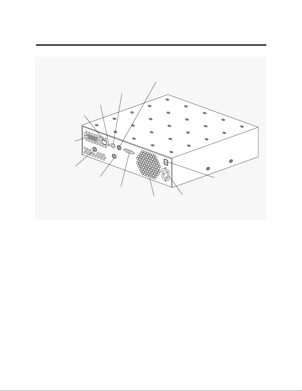
Figure 1-1 Input/Output Connections
Ethernet Port
10Base2 BNC
Ethernet Port
Selection Switch
10BaseT
Link Status Indicator
Ethernet Port
10BaseT RJ-45
Ethernet Port
10Base5 AUI
Cable TV Receive Port
Cable TV Transmit Port
Serial RS 232
Port
Fan Grill
AC On/Off
Switch
The ChannelWorks Bridge AC
Power Receptacle
1-4 ChannelWorks Cable TV Installer’s Guide

Ethernet Port Selection Switch
The Ethernet Port Selection Switch is located on the back panel between the Ethernet
RJ-45 and BNC Ports. When the Ethernet Port Selection Switch is pushed in, the
ChannelWorks Bridge can physically connect to an Ethernet network using its BNC
Port. When the Ethernet Port Selection Switch is in the Out position, the ChannelWorks Bridge can physically connect to an Ethernet network using either its RJ-45 Port
or its AUI Port.
Caution - You risk damaging the ChannelWorks Bridge and causing network problems
!
!
!
if you attempt to connect Ethernet networks to both AUI (10Base5) and RJ-45
(10BaseT) Ports at the same time.
Achtung - Wenn Sie gleichzeitig 10base5- und 10baseT-Netwerkschnittstellen an die
ChannelWorks-Brücke anschließen, besteht die Gefahr, daß Sie diese beschädigen und
Probleme in ihrem Netzwerk verursachen..
Attention - Vous risquez d'endommager ChannelWorks Bridge et de causer des perturbations sur le réseau si vous essayez de connecter simultanément les interfaces réseau
10base5 et 10baseT à ChannelWorks Bridge.
Aviso - Se pueden ocasionar daños al ChannelWorks Bridge y causar problemas en la
!
Cable TV Ports
Serial Port
red, si se intenta conectar simultáneamente los interfaces de red 10base5 y 10baseT a
ChannelWorks Bridge.
Two type F coaxial connectors provide the bridge’s interface to the cable TV network.
Figure 1-1 shows the location of the F connectors. The bridge’s port labeled Cable TV
Receive Port connects to the cable TV network’s forward channel. The bridge’s port
labled Cable TV Transmit Port connects to the cable TV network’s return channel.
The ChannelWorks Bridge serial port interface is used for configuring the bridge’s
operating parameters using a personal computer and performing out of band network
management
Introduction 1-5

The serial port connects the bridge to a PC in order to run the LCM. A nine-pin D-subminiature connector provides the interface to the PC. Refer to Chapter 3 and Appendix
A of the ChannelWorks Network Installer’s Guide for more information on how to con-
nect the ChannelWorks Bridge serial port to a PC.
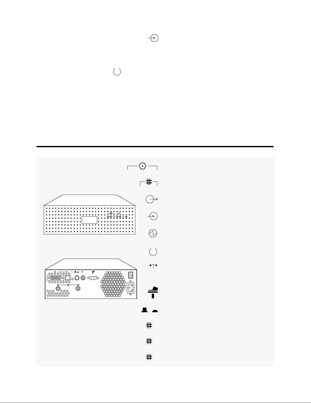
The ChannelWorks Bridge Identifying Symbols
Figure 1-2 provides descriptions of the graphic symbols denoting The ChannelWorks
Bridge interface ports, selection switch, and LEDs.
The following paragraphs describe the diagnostic and status LEDs of the bridge. All
LEDs are located on the front panel except for the 10BaseT Link Status LED. This
LED is located on the rear panel. Refer to Figure 1-2 for the locations of each LED.
10BaseT Link Status LED - Color Green
This LED is a status indicator located on the rear panel between the 10BaseT port and
the Ethernet Port Selection Switch. When this LED is lit, it indicates the 10BaseT link
is active.
Power On LED - Color Green
This LED is the main power indicator. When lit, this LED indicates there is DC power
being supplied to the ChannelWorks Bridge. When off, this LED indicates the AC
power has been removed from the ChannelWorks Bridge or the AC power has failed.
Ethernet Transmit LED - Color Green
When flashing or continuously lit, this LED indicates the ChannelWorks Bridge is
actively transmitting data on the Ethernet media selected.
Ethernet Receive LED - Color Green
When flashing or continuously lit, this LED indicates the ChannelWorks Bridge is
actively receiving data over the Ethernet media selected.
Broadband Transmit LED - Color Green
When flashing or continuously lit, this LED indicates the ChannelWorks Bridge is
actively transmitting data over the cable TV broadband media.
1-6 ChannelWorks Cable TV Installer’s Guide
Broadband Receive LED - Color Green
When flashing or continuously lit, this LED indicates the ChannelWorks Bridge is
actively receiving data over the cable TV broadband media.
Status LED - Color Green
When flashing slowly this LED indicates the ChannelWorks Bridge diagnostics passed
and the unit is ready to receive its operating parameters or boot operational software.
When this LED flashes rapidly it indicates the ChannelWorks Bridge self diagnostics
passed and the operational software is running.
Figure 1-2 Identifying Symbols
Cable TV Reference Symbol
Ethernet Reference Symbol
Cable TV/Ethernet Transmit LED/Port Symbol
Cable TV/Ethernet Receive LED/Port Symbol
Power On LED Symbol
Status LED Symbol
321
Block Synchronization LED Symbol
Serial Port Symbol
Ethernet Port Selection Switch Symbol
Ethernet 10Base5 “Thickwire” Port Symbol
1
Ethernet 10BaseT “Unshielded Twisted Pair”
2
Port Symbol
Ethernet 10Base2 “ThinWire” Port Symbol
3
Introduction 1-7

Block Sync LED - Color Green
This LED is a cable TV broadband network status indicator. Its primary purpose is to
display the status of the cable TV network after power up. When continuously lit, this
LED indicates the ChannelWorks Bridge has established block synchronization and the
cable TV broadband link is active.
Specifications
The following sections cover specifications for the ChannelWorks Bridge, TransMaster
and cable TV network.
Dimensions and Weight
ChannelWorks Bridge
The physical dimensions and weight of the ChannelWorks Bridge are provided below.
Height 3.47-in
Width 11.5-in
Depth 11.5-in
Rear Clearance 0.7-in
Weight 12-lbs
TransMaster
The physical dimensions of the TransMaster are provided below:
Height 1.75-in
Width 17.5-in
Depth 8-in
Weight 7.5-lbs
Power Requirements
ChannelWorks Bridge
The power requirements of the ChannelWorks Bridge are provided below:
100 - 120 Vac single phase, 3 wire (Domestic Standard)
0.7 A
220 - 240 Vac single phase, 3 wire (International Standard)
0.45 A
Frequency: 50 - 60 Hz
1-8 ChannelWorks Cable TV Installer’s Guide

TransMaster
The power requirements of the TransMaster are provided below:
115 Vac
15 Watts
Frequency: 60 Hz
Normal Operating Environment
ChannelWorks Bridge
The normal operating environment of the ChannelWorks Bridge is provided below:
Operating Temperature: 10 to +40° Centigrade.
Storage Temperature: -40 to +66° Centigrade.
Humidity: 10% to 95%, noncondensing
TransMaster
The normal operating environment of the TransMaster is provided below:
Operating Temperature: 10 to +40° Centigrade.
Humidity: 20% to 80%, noncondensing
RF Electrical Specifications
ChannelWorks Bridge
The RF Electrical Specifications of the ChannelWorks Bridge are provided below:
Data Rate 10 Mb/s
Modulation Quadrature Phase Shift Keying
Spectral Efficiency 1.67 bits/Hz
Transmitter
Minimum Frequency Range 10 to 174 MHz
Frequency Stability ±15 ppm
Bandwidth 6 MHz
Power Output +54 dBmV ±3 dB over min frequency range
Carrier On/Off Ratio 67 dB or better
Spurious Rejection −40 dBc (on channel)
+10 dBc (off channel)
Introduction 1-9

TransMaster
Set-up and installation procedures for the translator are located in Chapter 3, “Setting
Up the Headend Translator.” The following list contains the RF electrical specifications for the TransMaster single channel translator.
Spurious Output -45 dBc
Return Loss (TX Port) 14 dB
Receiver
Minimum Frequency Range 54 to 550 MHz
Receive Level −5 to +15 dBmV
BER @ 25 dB C/N <1 in 10
9
Return Loss (RX Port) 10 dB
Input Frequency Range 8.75 to 550 MHz
Output Frequency Range 51 to 550 MHz
Frequency Step 250 KHz
Frequency Stability/Accuracy ±750 Hz 0°C to 40°C
Gain 30 to 50 dB (adjustable)
Bandwidth −3 dB @ >5.2 MHz
−40 dB @ >7 MHz
Spurious Products >60 dB below max output level
Cable TV Network Requirements
The following list contains the required specifications that a cable TV network must
meet in order for the ChannelWorks Bridge to operate properly when connected.
Nominal Impedance 75 ohms
Return Path Outlet-to-Outlet Variation ≤6 dB
Amplitude Flatness ±1 dB
Group Delay ±10 nsec
Carrier to Hum Ratio ≥34 dB
Carrier to Noise Ratio ≥40 dB
Carrier to Second Order Beat ≥60 dB
Carrier to Third Order Beat ≥78 dB
Carrier to Adjacent Channel Interference ≥36 dB
1-10 ChannelWorks Cable TV Installer’s Guide
 Loading...