

Digital Equipment ChannelWorks Network Installer Manual

ChannelWorks
Network Installer’s Guide
Part Number: EK-DECTV-IN. B01

Federal Communications Commission (FCC)
Radio Frequency Interference Statement
The following statement applies only to the ChannelWorks bridge:
This equipment generates, uses, and may emit radio frequency energy. The equipment
has been type tested and found to comply with the limits for a Class A digital device
pursuant to Part 15 of FCC rules, which are deigned to provide reasonable protection
against such radio frequency interference.
Any changes or modification to this equipment may void the user’s authority to operate
this equipment.
Operation of this equipment in a residential area may cause interference in which case
the user at his own expense will be required to take whatever measures may be required
to correct the interference.

ChannelWorks
Network Installer’s Guide
February 1994
This manual, in conjunction with the
Installer’s Guide
describes how to install the ChannelWorks bridge. This manual
is intended for the hardware installer and network manager.
Supersession/Update Information: This is a revised manual.
and the
ChannelWorks Management
ChannelWorks Cable TV
manual,
Part Number: EK-DECTV-IN. B01

EK-DECTV-IN. B01
February 1994
The information in this document is subject to change without notice and should not be construed
as a commitment by Digital Equipment Corporation. Digital Equipment Corporation assumes no
responsibility for any errors that may appear in this document.
© Digital Equipment Corporation 1994. All rights reserved.
Restricted Rights: Use, duplication, or disclosure by the U. S. Government is subject to restrictions as set forth in subparagraph (c) (1) (ii) of DFARS 252.227-7013, or in F AR 52.227-19, or in
FAR 52.227-14 Alt. III, as applicable.
Possession, use, or copying of the software described in this publication is authorized only pursuant to a valid written license from Digital or an authorized sublicensor.
No responsibility is assumed for the use or reliability of software on equipment that is not supplied by Digital or its affiliated companies.
Digital Equipment Corporation makes no representations that the use of its products in the manner described in this publication will not infringe on existing or future patent rights, nor do the
descriptions contained in this publication imply the granting of licenses to make, use, or sell
equipment or software in accordance with the description.
The following are trademarks of Digital Equipment Corporation: ChannelWorks, Digital, LAT,
The Digital Channel, DECnet, PATHWORKS, POLYCENTER, and the DIGITAL logo.
UniLINK and LANcity are registered trademarks of LANcity Corporation.
IBM, OS/2, and Personal Computer AT are registered trademarks of International Business
Machines Corporation.
Microsoft and MS-DOS are registered trademarks, and Windows is a trademark of Microsoft Corporation.
Procomm is a registered trademark of Datastorm Technologies.
SNMPc is a trademark of Castle Rock Computing.
Hayes is a registered trademark of Hayes Microcomputer Products Inc.

EMC Class A Notices
Warning - This is a Class A product. In a domestic environment this product may
cause radio interference in which case the user may be required to take adequate measures.
Achtung - Diese ist ein Gerat Funkstorgrenzwertklasse A. In Wohnbereichen konnen
bei Betreib dieses Gerates Rundfunkstorungen auftreten, in welchen Fallen der
Benutzer fur entsprechende Gegenmassnahmen verantwortlich ist.
Attention - C’est un produit de Classe A. Dans un environnement domestique, ce produit risque de creer des interferences radioelectriques, il appartiendra alors a l’utilisateur de prendre les mesures specifiques appropriees.
Canadian Department of Communications Compliance Statement
The Canadian Department of Communications label identifies certain equipment. This
certification means that the equipment meets certain telecommunications network protective, operational, and safety requirements. The Department does not guarantee that
the equipment will operate to the user’s satisfaction.
Before installing this equipment, users should ensure that it is permissible to be connected to the facilities of the local telecommunications company. The equipment must
also be installed using an acceptable method of connection. In some cases, the company’s wiring associated with a single line individual service may be extended by
means of a certified connector assembly (telephone extension cord). The customer
should be aware that compliance with the above conditions may not prevent degradation of service in some situations.
Repairs to certified equipment should be made by an authorized Canadian maintenance
facility designated by the supplier. Any repairs or alterations made by the user to this
equipment, or equipment malfunctions, may give the telecommunications company
cause to request the user to disconnect the equipment.
User’s should ensure for their own protection that the electrical ground connections of
the power utility, telephone lines, and internal metallic water pipe system, if present,
are connected together. This precaution may be particularly important in rural areas.
Caution -
!
the appropriate electrical inspection authority, or electrician, as appropriate.
Users should not attempt to make such connections themselves, but should contact
v

Acoustics - Declared values per ISO 9296 and ISO 7779
Sound Power Level Sound Pressure Level
L
BL
WAd,
pAm,
dBA
(bystander positions)
Product Idle/Operate Idle/Operate
DECTV-AA 5.0 35
[Current values for specific configurations are available from Digital representatives.
1 B = 10 dBA.]
Schallemissionswerte - Werteangaben nach ISO 9296 und ISO 7779/DIN EN27779
Schalleistungspegel Schalldruckpegel
L
BL
WAd,
pAm,
dBA
(Zuschauerpositionen)
Produkt Leerlauf/Betrieb Leerlauf/Betrieb
DECTV-AB 5.0 35
[Aktuelle Werte f|r spezielle Ausr|stungsstufen sind |ber die Digital Equipment Vertretungen erhdltlich. 1 B = 10 dBA.]
Nippon - Japan
vi

Contents
Preface
1 Introduction
Introduction..................................................................................................................................1-1
Pre-Installation Tasks ..................................................................................................................1-1
Required Tools and Materials .....................................................................................................1-2
How To Tell If The Cable TV Network Is Ready.......................................................................1-2
2 Physical Installation
Introduction .................................................................................................................................2-1
Unpacking The ChannelWorks Bridge Shipping Carton ............................................................2-1
Taking Inventory .................................................................................................................2-2
The ChannelWorks Bridge Shipping Container Contents....................................................2-2
Examining The ChannelWorks Bridge................................................................................. 2-4
Identifying Cables And Connectors .....................................................................................2-5
Selecting An Installation Area .................................................................................................... 2-6
Power And Grounding Requirements .................................................................................. 2-7
Cable Lengths ......................................................................................................................2-8
3 Set-Up and First Steps
Introduction .................................................................................................................................3-1
Installing The LANcity Subscriber Utility On A PC............................................................3-2
Setting Up User Accounts ....................................................................................................3-4
User Levels...........................................................................................................................3-6
Level One ...................................................................................................................... 3-6
Level Two...................................................................................................................... 3-6
Level Three.................................................................................................................... 3-6
Connecting A PC To The ChannelWorks Bridge Serial Port...............................................3-7
Selecting The Communications Port....................................................................................3-9
Reading The ChannelWorks Bridge Parameters................................................................3-10
Verifying The ChannelWorks Bridge Parameters.............................................................. 3-11
Modifying And Loading The ChannelWorks Bridge Parameters......................................3-15
Loading Modified Select Parameter Groups ...................................................................... 3-16
Loading All Parameter Groups........................................................................................... 3-17
vii

Contents
4 Starting The ChannelWorks Bridge
Introduction .................................................................................................................................4-1
Verifying Start Up........................................................................................................................4-1
Locating The Cable TV And Ethernet Network Connections .................................................... 4-2
Cable TV Network................................................................................................................ 4-2
Ethernet Network..................................................................................................................4-2
Start Up........................................................................................................................................4-3
Connecting To A Single-Cable, Cable TV Network............................................................4-6
Connecting To A Dual-Cable, Cable TV Network ..............................................................4-8
Connecting To The AUI Port ...............................................................................................4-9
Connecting To The BNC Port ............................................................................................ 4-10
Connecting to the RJ-45 Port.............................................................................................. 4-11
5 Troubleshooting
Introduction .................................................................................................................................5-1
Power LED ........................................................................................................................... 5-1
Status LED............................................................................................................................5-2
Block Sync LED...................................................................................................................5-2
Activity LEDs....................................................................................................................... 5-3
Appendix A Cables for Serial Devices
Introduction ................................................................................................................................A-1
General Description.................................................................................................................... A-1
Serial Modem Cables.................................................................................................................. A-2
Null Modem Cables....................................................................................................................A-2
Appendix B Pre-Installation Checklist
Introduction .................................................................................................................................B-1
Index
viii

Contents
Figures
2-1 Shipping Container Contents With Optional Equipment......................................................2-3
2-2 The ChannelWorks Bridge Back Panel.................................................................................2-4
2-3 Cables And Connectors.........................................................................................................2-5
2-4 The ChannelWorks Bridge Ventilation Areas.......................................................................2-7
3-1 Directory Location Dialog Box.............................................................................................3-3
3-2 Create Program Group Dialog Box.......................................................................................3-3
3-3 Admin Pull Down Menu........................................................................................................3-5
3-4 Add User Entry Window.......................................................................................................3-5
3-5 ChannelWorks Bridge Power On Diagnostics ...................................................................... 3-7
3-6 Serial Port Connection Window............................................................................................3-9
3-7 Bridge Pull Down Menu......................................................................................................3-10
3-8 Read NVRAM Window ...................................................................................................... 3-11
3-9 Parameter Pull Down Menu ................................................................................................3-15
3-10 Bridge Load Window ........................................................................................................ 3-16
4-1 Ethernet Port Selection Switch Location And Identifying Symbol....................................... 4-3
4-2 The ChannelWorks Bridge LED Indicators .......................................................................... 4-5
4-3 Connecting To A Single Cable, Cable TV Network.............................................................4-7
4-4 Connecting To A Dual Cable, Cable TV Network................................................................ 4-8
A-1 Null Modem Cable Wiring..................................................................................................A-3
Tables
3-1 ChannelWorks Bridge Operating Parameters......................................................................3-12
ix

x

About This Book
The ChannelWorks Network Installer’s Guide is the first book in the series of cable TV
bridge system documentation. It describes how to:
• Unpack the shipping carton(s)
• Connect cable TV network and Ethernet/802.3 network cables
• Use the PC Subscriber Utility to verify the ChannelWorks Bridge’s installation
parameters
• Power up the ChannelWorks Bridge
The ChannelWorks Network Installer’s Guide provides illustrated instructions for con-
necting the necessary cables such as the:
• AUI: 10Base5 Thickwire,
• BNC: 10Base2 ThinWire,
• RJ-45: 10BaseT Unshielded Twisted Pair
for the Ethernet network and the broadband coaxial drop cable for the cable TV network to the ChannelWorks Bridge.
Preface
Who Should Read This Book
The ChannelWorks Network Installer’s Guide is for use by installation technicians
trained to perform ChannelWorks Bridge installations.
xi

Document Organization
The ChannelWorks Network Installer’s Guide is organized as follows:
• Chapter 1, “Introduction,” explains planning and preparing to install the product.
This chapter describes required tools and explains verifying whether the cable TV
network is ready for ChannelWorks Bridge installation.
• Chapter 2, “Physical Installation,” describes selecting a work area, bridge’s input/
output connections, and unpacking instructions. This chapter also graphically
identifies cables and connectors you will use during installation.
• Chapter 3, “Set-Up and First Steps,” describes how to interface with the
ChannelWorks Bridge using its serial port to verify the unit’s installation parameters.
• Chapter 4, “Starting Up the ChannelWorks Bridge,” explains how to attach the
ChannelWorks Bridge to a cable TV network and to an Ethernet network. This
chapter also explains how to turn the power on and verify the ChannelWorks
Bridge is operational.
• Chapter 5, “Troubleshooting,” provides an introductory level of corrective instruction required if the ChannelWorks Bridge does not work after you perform all
installation procedures.
xii ChannelWorks Network Installer’s Guide

Conventions Used In This Guide
Convention Meaning
Italic Font Italic Font is used for titles books or to give special empha-
sis. For example:
For more information, refer to the ChannelWorks Cable TV
Installer’s Guide.
Special Type Special Type (Courier Font) indicates messages or prompts
from the system that appear on your screen. For example:
Configuration successfully installed.
Special Bold Type
Special Bold Type (Courier Bold Font) is used within text
instructions and in screen examples to show characters or
words that you type. For example:
At the prompt, type AA000400AB04.
prompt> passwd
A Capitalized Word A Capitalized Word within text indicates a key that you
press. For example:
Press Return.
When you see two key names, press and hold the first key,
and then type the second character. For example:
To press Control-C, press and hold the Control key, and
then type an uppercase
C.
Preface xiii

Associated Documents
Refer to the following documents for further information:
• ChannelWorks Cable TV Installer’s Guide - Describes setting up the cable TV hea-
dend trranslator, preparing the cable TV network for data communications, configuring and installing the ChannelWorks Bridge, and TransMaster frequency switch
settings.
• ChannelWorks Management - Describes using the bridge’s Management Utility to
set up the ChannelWorks Bridge operating parameters, preparing the bridge for
Serial Line Interface Protocol operation, using the bridge’s enterprise specific MIB
variables to diagnose and resolve network problems, and accessing and interpretting the bridge’s SNMP enterprise specific MIB Support History file.
Safety Precautions
This preface provides safety precautions to follow when installing the ChannelWorks
Bridge.
For your protection, observe the following safety precautions when setting up your
equipment:
• Follow all warnings and instructions marked on the equipment.
• Ensure that the voltage and frequency of your power source matches the voltage
and frequency inscribed on the equipment’s electrical rating label.
• Never push objects of any kind through openings in the equipment. Dangerous
voltages may be present. Conductive foreign objects could produce a short circuit
that could cause fire, electric shock, or damage to your equipment.
xiv ChannelWorks Network Installer’s Guide

Symbols
The following international symbols appear in this book when you must perform procedures requiring proximity to electrical current.
!
!
!
!
Caution - You risk damaging your equipment if you do not heed the instructions.
Achtung - Wenn Sie die Anweisungen nicht beachten, könnten Sie Ihre Geräte beschä-
digen.
Attention - vous risquez d'endommager votre équipement si vous ne vous conformez
pas aux instructions.
Precaución - Se pueden ocasionar daños al equipo si no se siguen atentamente las
instrucciones.
Warning - Hazardous voltages are present. To lessen the risk of electrical shock and
danger to personal health, follow the instructions carefully.
Warnung - Im Gerät herrscht gefährliche Hochspannung. Beachten Sie die Anweisungen genau, um die elektrische Schläge und Gefahren für Ihre Gesundheit zu vermeiden.
Danger - Présence de tensions dangereuses. Pour limiter les risques d'accidents électriques et de blessures corporelles, suivez les instructions à la lettre.
Aviso - Existe la presencia de tensiones peligrosas. Para disminuir el riesgo de accidentes eléctricos y daños personales, hay que seguir las instrucciones al pie de la letra.
Preface xv

Modifications to Equipment
Do not make mechanical or electrical modifications to the equipment. The
ChannelWorks Bridge may not meet regulatory compliance if modified.
Placement of the ChannelWorks Bridge
Caution - To ensure reliable operation of the ChannelWorks Bridge and to protect it
!
!
!
from overheating, openings in the equipment must not be blocked or covered. The
ChannelWorks Bridge should never be placed near a radiator heat register.
Achtung - Um einen zuverlässigen Betrieb der ChannelWorks-Brücke zu gewährleisten und sie vor Überhitzung zu schützen, dürfen Geräteöffnungen nicht verstopft oder
abgedeckt werden. Die ChannelWorks-Brücke sollte nicht in der Hähe von Heizkörpern aufgestellt werden.
Attention - Pour assurer le bon fonctionnement de ChannelWorks Bridge et pour le
mettre à l'abri de toute surchauffe, les ouvertures ne doivent être ni entravées, ni recouvertes. ChannelWorks Bridge ne doit jamais être placé à proximité d'un accumulateur
de chaleur thermique.
Precaución - Para garantizar el buen funcionamiento de ChannelWorks Bridge y para
protegerlo de un eventual recalentamiento, las aberturas no deben quedar obstruidas o
!
recubiertas. ChannelWorks Bridge no debe jamás colocarse cerca de un acumulador de
calor térmico.
xvi ChannelWorks Network Installer’s Guide

Power Cord Connection
Warning - The ChannelWorks Bridge is designed to work with single-phase power
systems having a grounded neutral conductor. To reduce the risk of electrical shock, do
not plug the ChannelWorks Bridge into any other type of power system. Contact your
facilities manager or certified electrician if you are not sure what type of power is supplied to your building.
Warnung - Die ChannelWorks-Brücke ist für den Betrieb mit einphasigen Stromversorgungssystemen ausgelegt, die einen geerdeten neutralen Leiter haben. Um die
Gefahr elektrischer Schläge zu reduzieren, dürfen Sie das Gerät nicht an andere Stromversorgungssysteme anschließen. Wenn Sie nicht wissen, welche Stromart in Ihrem
Gebäude zur Verfügung steht, bitten Sie Ihren Hausverwalter oder einen zugelassenen
Elektriker um Auskunft.
Danger - ChannelWorks Bridge est conçu pour un fonctionnement avec des systèmes
d'alimentation mono-phasés pourvus d'un conducteur neutre mis à la terre. Pour limiter
les risques d'accidents électriques, ne connectez pas ChannelWorks Bridge à un autre
type d'alimentation. Contactez le directeur du site ou un électricien certifié si vous ne
connaissez pas le type d'alimentation dont est pourvu le bâtiment.
Aviso - ChannelWorks Bridge ha sido concebido para funcionar con sistemas de alimentación monofásicos provistos de un conductor neutro puesto a tierra. Para disminuir el riesgo de accidentes eléctricos, no hay que enchufar este equipo a ningún otro
tipo de sistema de alimentación. Hay que ponerse en contacto con el administrador de
la instalación o con un electricista autorizado en caso de duda sobre el tipo de alimentación que posee el edificio.
xvii

Warning - The ChannelWorks Bridge is shipped with a grounding type (three-wire)
power cord. To reduce the risk of shock, always plug the cord into a grounded power
outlet.
Warung - Die ChannelWorks-Brücke wird mit einem geerdeten (3 adrigen) Kabel
geliefert. Schließen Sie das Gerät immer an eine geerdete Steckdose an, um Stromschläge zu vermeiden.
Danger - ChannelWorks Bridge est livré avec un cordon d'alimentation bipolaire plus
terre (3 fils). Pour limiter les risques d'accidents électriques, branchez toujours ce cordon sur une prise de terre.
Aviso - ChannelWorks Bridge se entrega con un cable de alimentación provisto de un
contacto a tierra (3 hilos). Para disminuir el riesgo de accidentes eléctricos, hay que
conectar siempre este equipo a una toma de alimentación con conexión a tierra.
The ChannelWorks Bridge Cover
Warning - It is not safe to operate the ChannelWorks Bridge without the cover in
place. Failure to take this precaution may result in personal injury and system damage.
Warnung - Der Betrieb der ChannelWorks-Brücke ohne Abdeckung ist gefährlich.
Wenn Sie diese Vorsichtsmaßnahme nicht beachten, riskieren Sie Personen- und Sachschäden.
Danger - Il est dangereux d'utiliser ChannelWorks Bridge sans son couvercle. Le nonrespect de cette précaution peut entraîner des blessures corporelles ou endommager le
système.
Aviso - Puede resultar peligroso operar el ChannelWorks Bridge sin su tapa. Si no se
observa esta precaución se pueden sufrir daños personales o averiar el sistema.
xviii ChannelWorks Network Installer’s Guide

Known Problems
The following items are under investigation:
1. The ChannelWorks Bridge operation has been verified at frequencies corresponding to standard NCTA channel assignments. For optimal receiver operation avoid
using the following forward (RX) frequencies:
• 79.000 MHz
• 85.000
• 93.000
• 105.000
• 141.000
• 429.000
• 465.000 MHz
2. The LANcity Management Utility (LCM) prevents the user from entering illegal
and non-optimized Max Round Trip Delay values. However, the ChannelWorks
Bridge software does not prevent the user from entering less than optimal Max
Round Trip Delay value when performing SNMP “sets” on the enterprise specific
MIB variable lcmaxrndtripdel in the ASIC Parameters group.
3. The Support History Log does not consider an error code at two different error levels as unique, which could be misleading as in the following example:
If error 0x35 is logged as a level 2 and at a later time error id 0x35 is logged at a
level 4, when displaying the Support History Log the second error as shows as a
level 2 crash.
4. The LANcity Subscriber Utility (LCS) and the LCM do not operate properly on a
66 MHz PC.
5. The PROM Monitor’s printcfg command displays an incorrect software version
value under the “Vers” heading. The “Description” heading displays the correct
software version. You can also use the SNMP enterprise specific MIB variable
lcsoftware in the Revision Levels group to view the correct software version.
6. Counters from the interface group of the MIB-II are not implemented correctly for
the serial port.
7. The IPNetT oMediaTable and the atT able of MIB-II cannot be modified via SNMP.
The enterprise specific MIB variables lcmcastrx and lcbcastrx from the Sonic Stats
group are not implemented.
xix

xx ChannelWorks Network Installer’s Guide

Introduction
This manual explains how to install the ChannelWorks Bridge, a 10 Mb/s, Ethernet-tocable TV, transparent, spanning-tree bridge. This chapter covers the following topics:
• Tasks that need to be completed before beginning installation
• Tools necessary for installation
• How to tell that the cable TV network is certified for data delivery
Pre-Installation Tasks
This manual assumes that you have completed the following tasks:
1
Introduction
• The cable TV network has been prepared to communicate with the unit, that is,
certified for data delivery.
• The unit has already been configured with the correct receive and transmit frequencies for this network. The installation materials that are shipped with this
manual allow you to verify them but not to change them. If you need to change
them, you must have the ChannelWorks Cable TV Installer's Guide and authorized
software. Refer to Chapter 3, “Set-Up and First Steps,” for procedures to verify
preconfigured installation parameters.
1-1

Required Tools And Materials
• A 7/16-in open end wrench for attaching the cable TV cable to the unit.
• If you are going to be verifying the units’ installation parameters, a PC running
Windows 3.1, a terminal emulator , and a nine-pin null-modem cable to connect the
PC’s serial port with the bridge’s serial port
• For single-cable, cable TV networks, a subsplit, midsplit or highsplit diplex filter
(separately orderable item), if one is not already installed at the site; you will also
need short (18-in) attachment cables (RG6) (separately orderable) for the receive
and transmit ports of the diplex filters.
• Network connection cables (both cable TV and Ethernet networks).
• If the unit is being rack-mounted or wall-mounted, the Channelworks Bridge Rack
Mount or Wall Mount Kits (separately orderable), and the required mounting hardware (listed with the mounting instructions).
How To Tell If The Cable TV Network Is Ready
Before beginning installation of the unit, verify that the cable TV system meets the following criteria, and is ready to accept the unit. Check with the cable installer or cable
system owner if necessary:
• The system must be two-way active, and must be capable of carrying signals from
the unit inbound to the headend, as well as out-bound from the headend to the unit.
• The signal path must meet conditions as specified in the ChannelWorks Cable TV
Installer’s Guide and documented for your specific installation site in the PreInstallation Checklist. A sample Pre-Installation Checklist is provided in the
Appendix B.
• On single-cable systems, there must be a translator installed at the headend, operating at the correct transmit and receive frequencies.
Before installing the unit, verify that the transmit and receive frequencies that have
been assigned to the unit are correct. If the unit is set to the wrong frequencies, it will
not operate on the network, and could also disrupt other users of the cable TV system.
1-2 ChannelWorks Network Installer’s Guide

Hardware Installation
Introduction
This chapter describes:
• Unpacking the unit
• Identifying the contents
• Verifying the packing slip
• Finding a location for the unit
• Physically performing any installation necessary (rack- or wall-mounting)
Unpacking The ChannelWorks Bridge Shipping Carton
To unpack your ChannelWorks Bridge:
2
• Inspect the shipping carton before removing the bridge.
If there is evidence of damage to the carton, arrange for an agent of the carrier to
be present when you remove the ChannelWorks Bridge.
• Remove the bridge and the remaining contents of the shipping carton.
The ChannelWorks Bridge is packed tightly in protective foam molds. Carefully
remove it from the carton.
2-1

After unpacking the unit, save the box and packaging materials. You can:
• Use them in case you ever have to send the unit back,
Or
• Return them to the address on the box at no expense to you. The packaging materials will be re-used, and the box will be recycled.
Taking Inventory
Check the packing slip to verify you have everything you ordered. Figure 2-1 shows
the basic parts of the ChannelWorks Bridge. Figure 2-1 also shows additional parts
that you may have ordered, such as rack or wall mounts. Refer to the documentation
that comes with the separately ordered rack or wall mounts for directions on setting up
the ChannelWorks Bridge in a rack or on a wall.
The ChannelWorks Bridge Shipping Container Contents
The ChannelWorks Bridge shipping box contains the following:
• The ChannelWorks Bridge and its power cord
• A 3.5-in floppy disk containing the LANcity
®
Subscriber Utility (LCS) software, a
PC based utilities program used to verify the ChannelWorks Bridge operating
parameters
• One copy of this document (ChannelWorks Network Installer’s Guide)
2-2 ChannelWorks Network Installer’s Guide
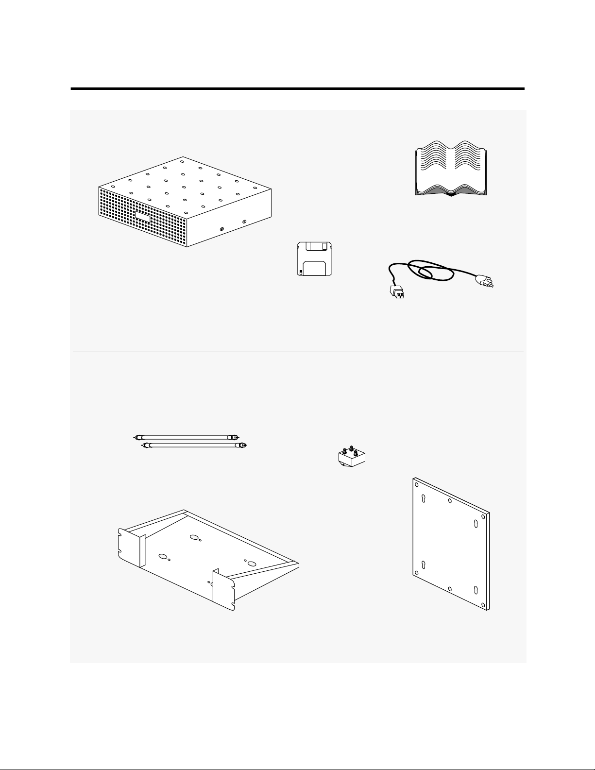
Figure 2-1 Shipping Container Contents With Optional Equipment
Contents
Network Installer’s
Guide
ChannelWorks
Subscriber Utility
(LCS)
Unit Power Cord
Additional Parts Ordered Separately
Coaxial Cables
Rack Mount Bracket
Diplex Filter
Wall Mount Bracket
Physical Installation 2-3
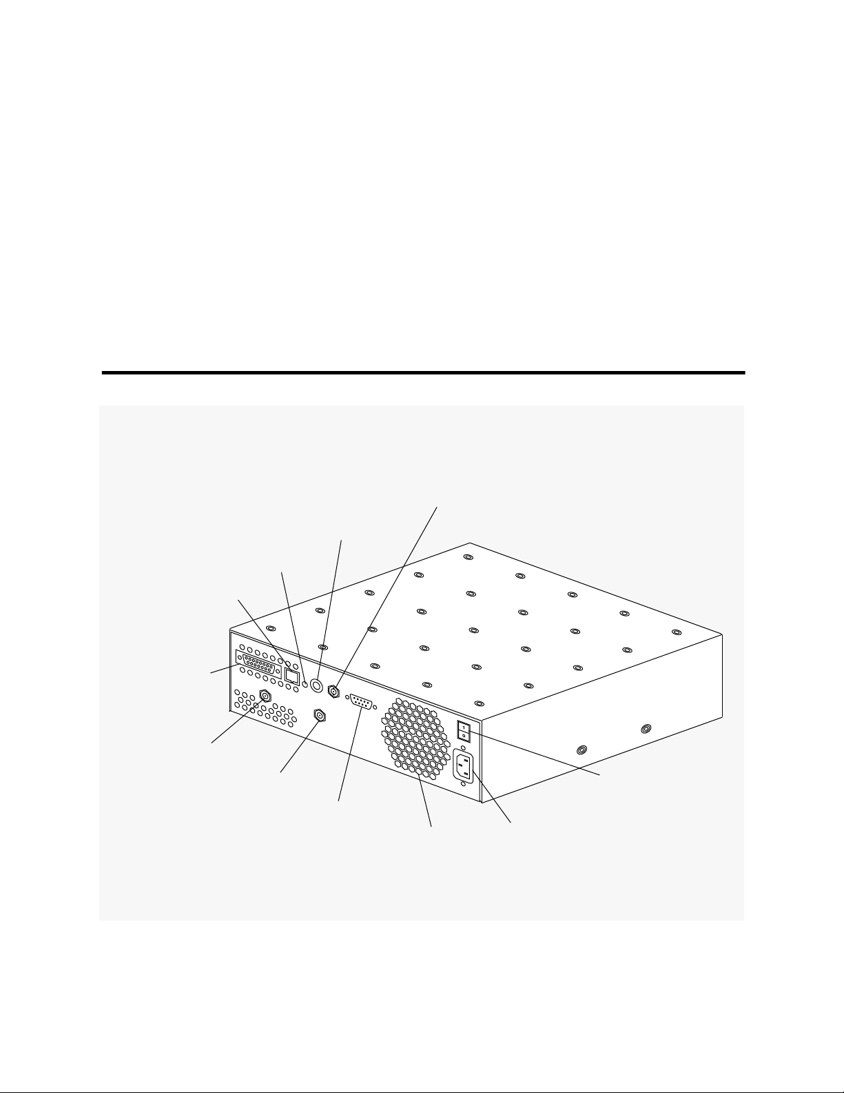
Examining The ChannelWorks Bridge
Examine the ChannelWorks Bridge to locate the parts on the back panel as you connect
the rest of the system. Figure 2-2 shows the locations of the following items: Ethernet
ports, serial port, cable TV transmit and receive ports, power input receptacle and the
AC On/Off switch.
If the unit is intended to be wall- or rack-mounted, you need the ChannelWorks Bridge
Wall Mount or Rack Mount kits to complete the installation. Contact your Digital representative for information about ordering these kits. A desktop installation needs no
additional hardware.
Figure 2-2 The ChannelWorks Bridge Back Panel
Ethernet Port
10Base2 BNC
Ethernet Port
Selector Switch
10BaseT
Link Status Indicator
Ethernet Port
10BaseT RJ45
Ethernet Port
10Base5 AUI
Cable TV Receive Port
Cable TV Transmit Port
Serial RS232
Port
Fan Grill
AC On/Off
Switch
ChannelWorks Bridge AC
Power Receptacle
2-4 ChannelWorks Network Installer’s Guide
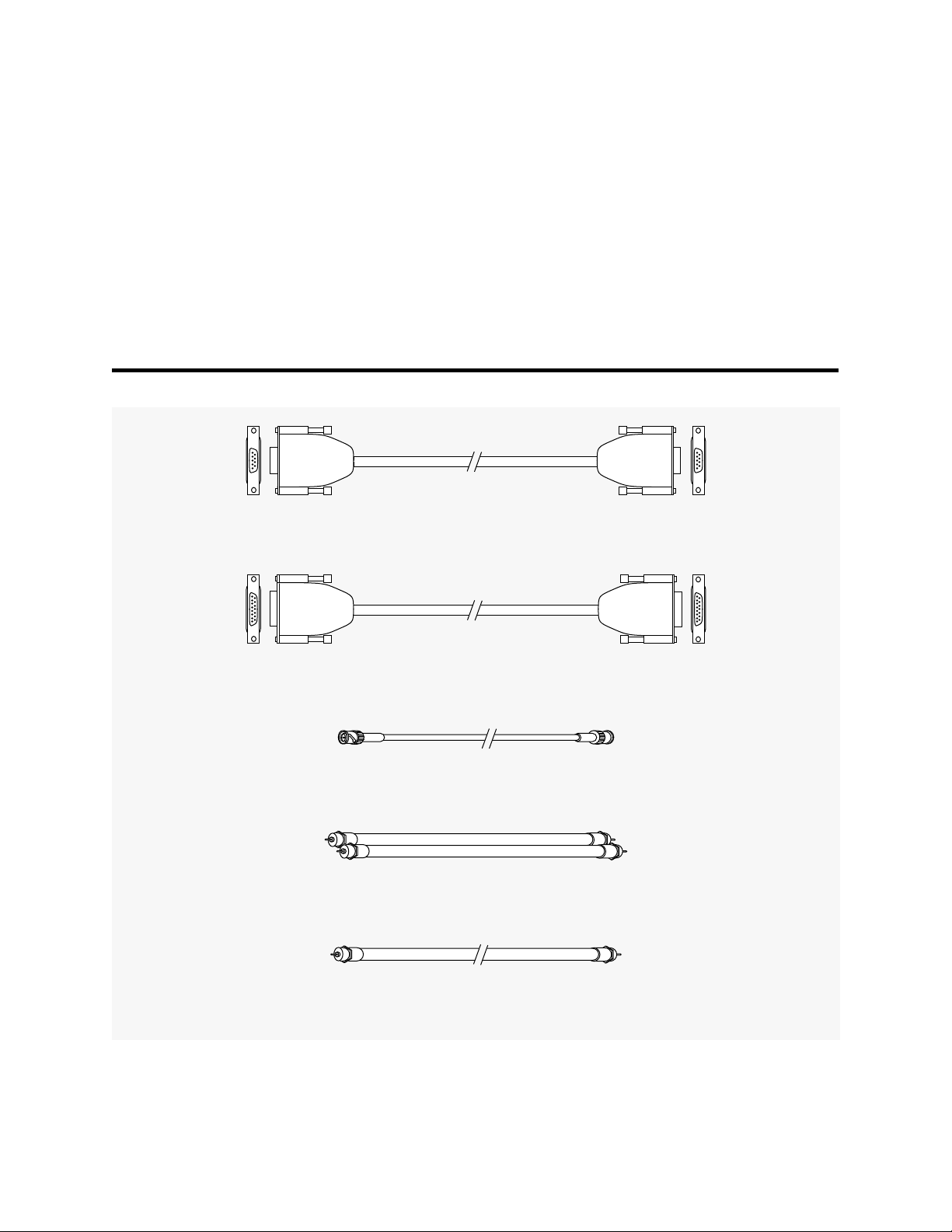
Identifying Cables And Connectors
Use Figure 2-3 to identify cables that you need. Refer to this figure as you follow the
procedures in Chapter 4 for setting up the system and for installing the ChannelWorks
Bridge on the Ethernet and cable TV networks.
Before you can install the ChannelWorks Bridge on your Ethernet you will need an
appropriate cable, one of the three types discussed in the “Cable Lengths” section.
Figure 2-3 Cables And Connectors
Serial Port Null Modem Cable with 9-Pin Connectors
Ethernet (10Base5 - AUI) Thickwire Cable with 15-Pin Connector
Ethernet (10Base2- BNC) Thinwire Cable with BNC Connector
Diplex Filter Transmit and Receive Coax Cables with F Connectors
Cable TV Coaxial Cable with F Connectors
Physical Installation 2-5
 Loading...