

Digital Equipment CELEBRIS XL 5100, CELEBRIS XL 590 DP, CELEBRIS XL 5100 DP, CELEBRIS XL 5120, CELEBRIS XL 5133 Service Maintenance Manual
...
Service
Maintenance
Manual
CELEBRIS XL & XL
DP
PC
EK-A0823-SV. B01
Copyright Digital Equipment Corporation
All rights reserved

March 1996
March 1996
The information in this document is subject to change without notice and should not be construed as a
commitment by Digital Equipment Corporation.
Digital Equipment Corporation assumes no responsibility for any errors that might appear in this
document.
The software, if any, described in this document is furnished under a license and may be used or copied
only in accordance with the terms of such license. No responsibility is assumed for the use or reliability of
software or equipment that is not supplied by Digital Equipment Corporation or its affiliated companies.
Restricted Rights: Use, duplication, or disclosure by the U.S. Government is subject to restrictions as set
forth in subparagraph (c) (1) (ii) of the Rights in Technical Data and Computer Software clause at DFARS
252.227-7013.
Copyright Digital Equipment Corporation
All Rights Reserved
The following are trademarks of Digital Equipment Corporation:
CELEBRIS, and the Digital logo.
The following are third party trademarks:
MS-DOS and Windows and Windows NT and Windows NT Server are trademarks of Microsoft Corp.
Novell and Netware are trademarks of Novell, Inc.
SCO and Open Desktop are trademarks of The Santa Cruz Operation, Inc.
UNIX is a registered trademark of UNIX System Laboratories, Inc.
Pentium® Pro is a registered trademark of Pentium.
All other trademarks and registered trademarks are the property of their respective holders.
Created by:
MCS Logistics Engineering - Nijmegen
Printed in Ireland

Digital CELEBRIS XL & XL
DP
PC Table of Contents
MCS Logistics Engineering - Nijmegen 3
Table of Contents
REVISION HISTORY ................................................................................................................................7
PREFACE ....................................................................................................................................................8
CHAPTER 1 PRODUCT DESCRIPTION..............................................................................................9
P
RODUCT INTRODUCTION...............................................................................................................................9
P
RODUCT MODELS INFORMATION................................................................................................................11
CELEBRIS XL & XL
DP
Models (FR-8xxWW)......................................................................................11
CELEBRIS XL & XL
DP
Models (FR-AxxWW)......................................................................................12
Celebris XL Pentium-Pro models............................................................................................................13
CHAPTER 2 SYSTEM UTILITIES & CONFIGURATION...............................................................15
S
YSTEM UTILITIES........................................................................................................................................15
Before Using System Utilities.................................................................................................................15
Restoring Win95 Factory-Installed Software..........................................................................................16
Restoring WFW Factory-Installed Software............................................................................................16
Restoring Windows NT Factory-Installed Software................................................................................17
Using System Utilities ............................................................................................................................17
PHLASH.EXE........................................................................................................................................17
Before Using PHLASH.EXE..................................................................................................................18
Creating a Crisis Recovery Diskette .......................................................................................................18
Using the Crisis Recovery Diskette.........................................................................................................19
Upgrading The BIOS..............................................................................................................................19
Upgrading the BIOS to a New Language................................................................................................20
Using EPP3NS.EXE to Configure an EPP Parallel Port.........................................................................20
Loading SCSI Drivers.............................................................................................................................21
BIOS S
ETUP UTILITY ...................................................................................................................................21
Running the BIOS Setup Utility .............................................................................................................21
Manoeuvring through Setup....................................................................................................................22
Updating The Configuration...................................................................................................................23
Helpful Hints...........................................................................................................................................23
Main Menu Options................................................................................................................................24
Memory and Cache Options ...................................................................................................................25
Boot Options...........................................................................................................................................27
Keyboard Features..................................................................................................................................28
Integrated Peripherals..............................................................................................................................28
Advanced Chipset Control Options ........................................................................................................30
Security Options .....................................................................................................................................31
Power Options.........................................................................................................................................33

Table of Contents Digital C ELEBRIS XL & XLDP PC
4 M C S Logistics Engineering - Nijm egen
CHAPTER 3 SERVICE PROCEDURES.............................................................................................. 35
S
AFETY REQUIREMENTS..............................................................................................................................35
Recommended Tools.............................................................................................................................. 36
Other Materials Needed.......................................................................................................................... 36
Special Tools Required........................................................................................................................... 36
Remedial Diagnostic Test Software .......................................................................................................36
Recommended Virus Detection and Cleanup Software.......................................................................... 36
ECO/FCO I
NFORMATION ............................................................................................................................37
BIOS Version Information..................................................................................................................... 37
R
EMOVING THE SIDE PANEL........................................................................................................................ 37
C
OMPUTER COMPONENTS............................................................................................................................ 39
E
XPANSION SLOTS.......................................................................................................................................40
M
AIN LOGIC BOARD SWITCHES/JUMPERS.................................................................................................... 41
Main Logic Board Jumper Settings........................................................................................................ 41
Main Logic Board Jumper Locations..................................................................................................... 42
C
OMPUTER MEMORY CONFIGURATIONS...................................................................................................... 43
Memory Configurations (Pentium series)............................................................................................... 43
Memory Configurations for Pentium-Pro............................................................................................... 45
Non-Interleaved Modes.......................................................................................................................... 45
Non-Interleaved Modes (continued)....................................................................................................... 47
Installing Single In-Line Memory Modules (SIMMs)............................................................................ 48
Main Logic Board SIMM Socket Locations........................................................................................... 50
P
ART REMOVAL AND REPLACEMENT PROCEDURES..................................................................................... 51
Removing Devices in the Upper Drive Bay Area................................................................................... 51
Removing Devices in the Lower Drive Bay Area................................................................................... 52
Removing Main Logic Board................................................................................................................. 54
Removing Fan / Speaker Assembly........................................................................................................ 55
Removing Power Supply........................................................................................................................ 57
Removing the CPU Module ................................................................................................................... 59
Replacing the Computer Battery/Real Time Clock (RTC)..................................................................... 60
U
PGRADING PROCEDURES ........................................................................................................................... 62
Identification.......................................................................................................................................... 62
Upgrading the CPU module ................................................................................................................... 63
CPU Module Jumper Settings (Pentium modules)................................................................................. 65
Upgrading the CPU (Pentium-Pro modules).......................................................................................... 67
CPU Module Component Locations (Pentium-Pro)............................................................................... 69
Setting Clock Frequency........................................................................................................................ 70
Setting Bus Speed .................................................................................................................................. 70
Replacing the Voltage Regulator Card (Pentium-Pro)............................................................................ 71
Setting Voltage Regulation..................................................................................................................... 71
Installing Mass Storage Devices............................................................................................................. 72
C
ONNECTING DEVICES................................................................................................................................. 76
Diskette Drive and IDE Drive Data Cable Connections......................................................................... 76
SCSI Cable Connections........................................................................................................................ 77

Digital CELEBRIS XL & XL
DP
PC Table of Contents
MCS Logistics Engineering - Nijmegen 5
CHAPTER 4 TROUBLESHOOTING...................................................................................................79
I
NITIAL TROUBLESHOOTING .........................................................................................................................79
B
EEP CODES.................................................................................................................................................80
POST
AND BOOT MESSAGES........................................................................................................................80
POST and Boot Error Messages..............................................................................................................80
POST and Boot Informational Messages................................................................................................83
C
OMPUTER TROUBLESHOOTING...................................................................................................................85
D
ISK DRIVE TROUBLESHOOTING..................................................................................................................90
M
ONITOR TROUBLESHOOTING......................................................................................................................90
CD-ROM Troubleshooting .....................................................................................................................91
QAP
LUS/FE ERROR MESSAGES....................................................................................................................92
CHAPTER 5 DEVICE MAPPING.........................................................................................................93
CPU Memory Address Map (Full Range)...............................................................................................93
Memory Address Map (Full Range, 6150 and higher CPUs)..................................................................94
CPU Memory Address Map (PC Compatibility Range) .........................................................................94
CPU I/O Address Map............................................................................................................................94
I/O Address Map.....................................................................................................................................95
Computer Interrupt Levels......................................................................................................................95
DMA Channel Assignment.....................................................................................................................95
PCI Configure Space Address Map.........................................................................................................96
CHAPTER 6 PASS / FAIL CRITERIA.................................................................................................97
APPENDIX A SERVICE NOTES..........................................................................................................99
APPENDIX B USEFUL INFORMATION..........................................................................................101
R
ELATED DOCUMENTATION.......................................................................................................................101
O
N-LINE BULLETIN BOARDS......................................................................................................................101
DOCUMENT FEEDBACK.....................................................................................................................103
PERSONAL NOTES...............................................................................................................................105
READERS COMMENTS..........................................................................................................................109

Table of C ontents Digital CELEBRIS XL & XLDP PC
6 M C S Logistics Engineering - Nijm egen
Table of Figures
Figure 2 - 1 BIOS Setup Utility Flow Chart............................................................................................... 22
Figure 3 - 1 Unlocking and Removing the Side Panels.............................................................................. 38
Figure 3 - 2 Model 870WW Computer Components.................................................................................. 39
Figure 3 - 3 Model A03 WW Computer Components................................................................................ 39
Figure 3 - 4 CELEBRIS XL Expansion Board Slots..................................................................................40
Figure 3 - 5 Main Logic Board Jumper Locations...................................................................................... 42
Figure 3 - 6 Installing a SIMM................................................................................................................... 49
Figure 3 - 7 Main Logic Board SIMM Socket Locations...........................................................................50
Figure 3 - 8 Removing a Device from the Upper Drive Bay Area.............................................................. 51
Figure 3 - 9 Removing the Lower Drive Bay Assembly............................................................................. 52
Figure 3 - 10 Removing the Lower Drive Bay Devices.............................................................................. 53
Figure 3 - 11 Removing the Main logic Board........................................................................................... 54
Figure 3 - 12 Removing the Fan / Speaker Assembly (Pentium)................................................................ 55
Figure 3 - 13 Removing the Fan / Speaker Assembly (Pentium-Pro)......................................................... 56
Figure 3 - 14 Removing the ON/OFF Switch.............................................................................................57
Figure 3 - 15 Removing the power plug..................................................................................................... 57
Figure 3 - 16 Removing the screws at the rear and Power Supply.............................................................. 58
Figure 3 - 17 Removing the CPU Module.................................................................................................. 59
Figure 3 - 18 Installing the Computer Battery/Real-Time Clock................................................................ 61
Figure 3 - 19 Installing a New CPU........................................................................................................... 64
Figure 3 - 20 Secondary Cache Upgrade Socket and Jumper Locations .................................................... 66
Figure 3 - 21 Releasing the Pentium® Pro Processor Assembly................................................................ 67
Figure 3 - 22 Installing a New Pentium® Pro Processor Assembly............................................................ 68
Figure 3 - 23 CPU Module Component Locations..................................................................................... 69
Figure 3 - 24 J5 Switch Location ............................................................................................................... 69
Figure 3 - 25 Voltage Regulator Card........................................................................................................ 71
Figure 3 - 26 Removing Plastic Filler Panel from Upper Drive Bay.......................................................... 72
Figure 3 - 27 Removing the Front Door.....................................................................................................73
Figure 3 - 28 Inserting a Device into Upper Drive Bay.............................................................................. 75
Figure 3 - 29 Diskette Drive and IDE Drive Data Cable Connections ....................................................... 76
Figure 3 - 30 SCSI Cable Connections....................................................................................................... 77

Digital CELEBRIS XL & XL
DP
PC Preface
MCS Logistics Engineering - Nijmegen 7
Revision History
Revision A01
This was the original release of the Service Maintenance Manual describing the
CELEBRIS XL & XL
DP
PC in its original configuration.
Revision B01
This revision of the CELEBRIS XL & XL
DP
PC Service Maintenance Manual,
incorporates updated configurations and various models that have been added.

Table of C ontents Digital CELEBRIS XL & XLDP PC
8 M C S Logistics Engineering - Nijm egen
Preface
The Digital CELEBRIS XL & XLDP Service Maintenance Manual is a troubleshooting guide that can be
used for reference when servicing the CELEBRIS XL & XL
DP
line of PC’s.
Digital Equipment Corporation reserves the right to make changes to the Digital CELEBRIS XL & XL
DP
series without notice. Accordingly, the diagrams and procedures in this document may not apply to the
computer(s) to be serviced since many of the diagnostic tests are designed to test more than one product.
CAUTION
Digital recommends that only A+ certified engineers attempt to repair this equipment.
All troubleshooting and repair procedures are detailed to support subassembly/module
level exchange. Because of the complexity of the indivual boards and subassemblies, no
one should attempt to make repairs at component level or to make modifications to any
printed wiring board. Improper repairs can create a safety hazard. Any indications of
component replacement or printed wiring board modifications may void warranty or
exchange allowances.

Digital CELEBRIS XL & XL
DP
PC Product Description
MCS Logistics Engineering - Nijmegen 9
Chapter 1 Product Description
Product Introduction
Digital CELEBRIS XL & XLDP computers are high-performance personal computers featuring the latest
in microprocessor and PCI local bus technology. They can be used as stand-alone computers, as clients, or
as servers in a network environment. Developed using the latest in modular CPU, PCI local bus, PCIbased SCSI technology, and a host of high-performance options, the CELEBRIS XL family offers the most
advanced computers in their class. It also includes Pentium-Pro (P6) models.
The following models are available:
♦ CELEBRIS XL 590 90 MHz Pentium
♦ CELEBRIS XL 590 DP 90 MHz Pentium (Dual Processor)
♦ CELEBRIS XL 5100 100 MHz Pentium
♦ CELEBRIS XL 5100 DP 100 MHz Pentium (Dual Processor)
♦ CELEBRIS XL 5120 120 MHz Pentium
♦ CELEBRIS XL 5133 133 MHz Pentium
♦ CELEBRIS XL 5133 DP 133 MHz Pentium (Dual Processor)
♦ CELEBRIS XL 5166 166 Mhz Pentium
♦ CELEBRIS XL 5166 DP 166 Mhz pentium (dual processor)
♦ CELEBRIS XL 150 Mhz Pentium Pro

Product Description Digital C ELEBRIS XL & XLDP PC
10 M C S Logistics Engineering - Nijm egen
Significant features include:
♦ PCI local bus technology
♦ Also available as 150 MHz Pentium-Pro processor
♦ Upgradable ZIF (Zero Insertion Force) socket 2 x ZIF 5
♦ 8MB system RAM minimum, expandable to 384MB, 512MB for pentium pro
♦ Alpha AXP upgradable
♦ 256KB asynchronous cache on single pentium processor variants
♦ 512KB asynchronous cache on dual processor variants
♦ Plug and Play
♦ On-board IDE/FDU controller
♦ flash BIOS
♦ On-board PCI SCSI-2 Controller, supports Fast SCSI-2
♦ Two PCI slots, one PCI/ISA interleaved, three ISA expansion slots (one PCI slot used for VGA
adapter)
Choice ofvideo cards:
♦ S3 864 PCI/VGA card, 2MB DRAM, upgradable to 4MB
♦ High performance DIAMOND STEALTH PCI/VGA card, 2MB DRAM, upgradable to 4MB
♦ High performance Matrox Millennium PCI card
♦ 2MB WRAM upgradable to 8MB
◊ 1600x1200, 256 colors, 60-72 Hz
*
◊ 1280x1024, 256-65K colors, 60-90 Hz *
◊ 1024x768, 256-65K colors, 60-120 Hz *
◊ 800x600, 256-16.7M colors, 60-120 Hz *
◊ 640x480, 256-16.7M colors, 60-120 Hz *
* The maximum values when supported by the monitor
Also for pentium pro:
♦ AccelGraphics AG300 dedicated 3D accelerator
♦ 5MB VRAM / frame-buffer
♦ 1280x1024, 65K-16.7M colors, 60-74 Hz
♦ 1024x768, 65K-16.7M colors, 60-74 Hz
♦ 2.5MB DRAM / 16 bit Z-buffer
♦ OpenGL support
♦ Dual Screen support
♦ VGA adapter required
See also: http://www.accelgraphics.com
♦ Flash BIOS
♦ “Energy Star” compliant
♦ 300 W power supply
Digital CELEBRIS XL & XL
DP
PC Product Description
MCS Logistics Engineering - Nijmegen 11
Front access bays:
♦ Three 5,25” x 1.6” bay
♦ One 3.5” x 1” bay for floppy
Internal access bays:
♦ One 3.5” x 1.6” bay for disks
Product Models Information
EC = English, French, German, Italian and Spanish.
ED = Danish, Dutch, English, Finnish, French (France excluded), Norwegian and Swedish.
CELEBRIS XL & XLDP Models (FR-8xxWW)
Product Model HDD Memory Cache Video adapter Options
CELEBRIS
XL590
FR-873WW-AD - 8MB 256KB None
FR-873WW-WH 540MB
SCSI-2
8MB 256KB S3 864 Video card
FR-873WW-WN 1GB
SCSI-2
16MB 256KB
(Sync.B
)
Diamond Stealth 64 CD-ROM
CELEBRIS
XL590 DP
FR-874WW-AD - 16MB 512KB
(Sync.B
)
None
CELEBRIS
XL5100
FR-875WW-AD - 16MB 256KB
(Sync.B
)
None
FR-875WW-WN 1GB
SCSI-2
16MB 256KB
(Sync.B
)
Diamond Stealth 64 CD-ROM
CELEBRIS
XL5100 DP
FR-876WW-AD - 16MB 512KB
(Sync.B
)
None

Product Description Digital C ELEBRIS XL & XLDP PC
12 M C S Logistics Engineering - Nijm egen
CELEBRIS XL & XLDP Models (FR-AxxWW)
Product Model HDD Memory Cache Video adapter Options
CELEBRIS
XL5100
FR-A03WW-AD - 16MB 256KB None
FR-A03WW-CN 1GB
SCSI-2
16MB 256KB Matrox Millennium 4x SCSI
CD-ROM
CELEBRIS
XL5100 DP
FR-A04WW-AD - 16MB 512KB None
FR-A04WW-CN 1GB
SCSI-2
16MB 512KB Matrox Millennium 4x SCSI
CD-ROM
CELEBRIS
XL5120
FR-A05WW-AD - 16MB 256KB None
FR-A05WW-CN 1GB
SCSI-2
16MB 256KB Matrox Millennium 4x SCSI
CD-ROM
CELEBRIS
XL5133
FR-A07WW-AD - 16MB 256KB None
FR-A07WW-CN 1GB
SCSI-2
16MB 256KB Matrox Millennium 4x SCSI
CD-ROM
CELEBRIS
XL5133 DP
FR-A08WW-AD - 16MB 512KB None
FR-A08WW-CN 1GB
SCSI-2
16MB 512KB Matrox Millennium 4x SCSI
CD-ROM
CELEBRIS
XL 5166
FR-A11WW-AD - 16MB 256KB None
FR-A11WW-CN 1 GB
SCSI-2
16MB 256KB Matrox Millennium 4x SCSI
CD-ROM
CELEBRIS XL
5166 DP
FR-A12WW-AD - 16MB 512KB None
FR-A12WW-CN 1 GB
SCSI-2
16MB 512KB Matrox Millennium 4x SCSI
CD-ROM
Digital CELEBRIS XL & XL
DP
PC Product Description
MCS Logistics Engineering - Nijmegen 13
Celebris XL Pentium-Pro models
Product Model HDD Memory Cache Video adapter Options
Celebris XL
6150
FR-A31WW-AD - 16MB 256KB None
FR-A31WW-CC 1 GB
SCSI-2
16MB 256KB Matrox Millennium 4x SCSI
CD-ROM
FR-A31WW-CN 2 GB
Wide
SCSI
with
Ultra
Wide
SCSI
adapter
32MB 256KB 4x SCSI
CD-ROM
CELEBRIS
XL6180
FR-A33WW-AD - 16MB 256KB None
FR-A33WW-CC 1GB
SCSI-2
16MB 256KB Matrox Millennium 4x SCSI
CD-ROM
FR-A33WW-CN 2GB
Wide
SCSI
with
Ultra
Wide
SCSI
adapter
32MB 256KB 3D Graphics
Accelrator
4x SCSI
CD-ROM
CELEBRIS
XL6200
FR-A34WW-AD - 16MB 256KB None
FR-A34WW-CC 1GB
SCSI-2
16MB 256KB Matrox Millennium 4x SCSI
CD-ROM
FR-A34WW-CN 2GB
Wide
SCSI
with
Ultra
Wide
SCSI
adapter
32MB 256KB 3D Graphics
Accelrator
4x SCSI
CD-ROM


Digital CELEBRIS XL & XL
DP
PC Utilities & Configuration
MCS Logistics Engineering - Nijmegen 15
Chapter 2 System Utilities &
Configuration
System Utilities
This chapter describes how to use the utilities and SCSI drivers supplied with the CELEBRIS XL
computer. In most cases, these utilities and drivers are factory installed on the hard disk drive and supplied
on diskettes.
♦ System utilities consisting of:
◊ EPP3NS.EXE − Enables to configure the computer for EPP operation.
◊ Logitech mouse drivers − Enables the computer to operate using a Logitech mouse.
◊ KP.EXE− Enables to set a keyboard and mouse password.
♦ Multilingual BIOS diskette consisting of:
◊ PHLASH.EXE (and associated runtime files).
◊ Binary multilingual BIOS images.
◊ PHLASH**.BAT files, where ** represents the multilingual BIOS. Run this file to upgrade the
BIOS to the desired language.
Refer to the section “PHLASH.EXE” later in this chapter, for additional information.
♦ MS-DOS/Windows, Windows NT, Netware, and OS/2 NCR SCSI Drivers − For additional
information on the directory structure for locating the desired driver file, see the README.TXT file
supplied with the SCSI driver.
♦ NCR SCO UNIX SCSI Drivers − For additional information on the directory structure for locating
the desired driver file, see the README.TXT file supplied with the SCSI driver.
Before Using System Utilities
When not familiar with utility programs and their uses, carefully read and understand this chapter before
attempting to use any of the utilities.

Utilities & C onfiguration Digital C ELEBRIS XL & XLDP PC
16 M C S Logistics Engineering - Nijm egen
Restoring Win95 Factory-Installed Software
To restore all factory-installed software, proceed as follows:
1) With the computer off, put the WIN 95 Companion CD into the CD drive.
2) Insert the CELEBRIS XL Win 95 Setup/Restore diskette into the diskette drive.
3) Turn the computer on.
The computer boots automatically from the diskette and prompts for confirmation.
4) Enter [Y] to proceed and the system software will then be copied to the hard disk drive.
5) When prompted to do so, insert the CELEBRIS XL Win 95 Setup/Restore diskette into the CD drive,
which will load the Getting Started and related help files and utilities.
6) When the files have been successfully copied, remove the boot diskette and the CD ROM.
7) Reboot the computer.
All system software is now loaded to the out-of-box factory condition.
NOTE If the computer can still perform basic functions, we recommend that the customer
makes backup diskettes of all important personal files. Restoring all factoryinstalled software will re-format the hard disk and erase all files.
Restoring WFW Factory-Installed Software
For Windows for Workgroups, run Make Media Master to create backup operating system and
utilities/drivers diskettes.
The Make Media Master program prompts to place diskettes in drive A and then automatically copies the
files to drive A.
To restore all factory-installed software, proceed as follows:
1) With the computer off, put disk 1 for the DOS setup into the diskette drive.
2) Turn the computer on. The computer will boot automatically from the diskette and prompts to install
the other diskettes.
3) When the files have been successfully copied, remove the boot diskette.
4) Reboot the computer.
All system software is now loaded to the out-of-box factory condition.
NOTE If the computer can still perform basic functions, we recommend that the customer
makes backup diskettes of all important personal files. Restoring all factoryinstalled software will re-format the hard disk and erase all files.

Digital CELEBRIS XL & XL
DP
PC Utilities & Configuration
MCS Logistics Engineering - Nijmegen 17
Restoring Windows NT Factory-Installed Software
To restore all factory-installed software, proceed as follows:
1) With the computer off, put the Windows NT OS CD into the CD drive.
2) Insert disk 1 of the Windows NT Setup diskettes into the diskette drive.
3) Turn the computer on.
The computer boots automatically from the diskette and prompts when to insert the other setup
diskettes. Follow the instructions in the Windows NT manual.
4) When prompted to do so, insert the CELEBRIS XL Software Restore CD into the CD drive, which
will load the related help files.
5) When the files have been successfully copied, remove the boot diskette and the CD ROM.
6) Reboot the computer.
All system software is now loaded to the out-of-box factory condition.
NOTE If the computer can still perform basic functions, we recommend that the customer
makes backup diskettes of all important personal files. Restoring all factoryinstalled software will re-format the hard disk and erase all files.
Using System Utilities
These utilities enable to upgrade or restore the BIOS and set the parallel port to EPP mode (only if the
printer supports EPP mode). If this is the first time using these utility programs, it is recommended to
follow the procedures in the order given.
1) Turn on or reboot the computer. If POST detects an error, refer to Chapter 4,“Troubleshooting” for
possible causes and suggested solutions.
2) If necessary, run PHLASH.EXE to restore or upgrade the BIOS to a new one provided.
3) Run EPP3NS.EXE to configure the computer for EPP operation.
PHLASH.EXE
All computers have BIOS software on a chip on the main logic board. This BIOS initializes hardware and
boots the operating system when the computer is turned on. The BIOS also provides access to other
services such as keyboard and disk drives.
The computer comes equipped with flash memory. This means that the BIOS can simply be restored by
running the PHLASH.EXE utility. The BIOS can also be upgraded to future releases by running
PHLASH.EXE along with any flash BIOS update diskette if necessary.

Utilities & C onfiguration Digital C ELEBRIS XL & XLDP PC
18 M C S Logistics Engineering - Nijm egen
Before Using PHLASH.EXE
Before using PHLASH.EXE to upgrade the BIOS, create a crisis recovery diskette. This diskette can than
be used to reprogram the BIOS in case the flash process built into the computer fails.
Have the following items available:
♦ A blank 3½-inch 1.44MB formatted diskette
♦ A diskette copy of the multilingual BIOS upgrade diskette
Creating a Crisis Recovery Diskette
To create a crisis recovery diskette:
1) Turn on the computer and allow the POST to complete.
2) If POST detects an error refer to Chapter 4, “Troubleshooting” and take the appropriate steps to
correct the problem. After the problem has been resolved, restart the computer.
Insert the multilingual BIOS diskette into the diskette drive and enter:
a:dir
The entry should show the following files are on the diskette:
MINIDOS.SYS
PHLASH.EXE
MAKEBOOT.EXE
MAKECRD.EXE
Note that there are some additional files as well. Refer to the README file on the diskette for
additional information.
3) Create an upgrade directory on the hard disk drive. For example, if the hard disk drive is c:>, enter at
the DOS prompt: md upgrade.
4) Copy the files from the multilingual BIOS diskette into the upgrade directory on the hard disk drive.
For example, from the DOS prompt enter: copy a:\upgrade\*.* c:\upgrade\*.* .
5) Insert a blank formatted diskette into drive A.
6) On drive A, make a directory for the files previously copied. For example, from the DOS prompt
enter:
md ugrade.
7) Return to the hard disk drive and copy the files. From the DOS prompt enter: makecrd.
The
QEOIGVH
command prompts for a recovery diskette to be placed in drive A and then
automatically copies the files to drive A.
8) Remove the crisis recovery diskette from drive A and store it in a safe place.

Digital CELEBRIS XL & XL
DP
PC Utilities & Configuration
MCS Logistics Engineering - Nijmegen 19
Using the Crisis Recovery Diskette
The crisis recovery diskette must be used only if the BIOS fails or if a BIOS upgrade was unsuccessful.
If the BIOS failed to flash properly or is corrupted in some way, the following sequence of events occur:
1) POST detects an error after a normal boot cycle or a BIOS upgrade.
Messages appear on the monitor screen to inform that the BIOS did not flash properly or has failed.
2) The BIOS in the bootblock memory automatically executes.
3) The computer attempts to find the correct BIOS files to execute the correct boot cycle.
4) The computer beeps several times.
This means the computer cannot properly boot using the BIOS files that were just copied during the
flash update.
5) The diskette drive begins searching for the crisis recovery diskette to restore the BIOS to its previous
known state.
Restore the BIOS to its previous known state by performing the following procedures:
1) Turn off the computer, unlock and remove the left-side cover, and set the recovery jumper (J34) to
enabled. Also, make sure that J35 is enabled.
Jumper J34 controls whether the computer is in recovery (Enabled) or normal (Disabled) operation.
Jumper J35 allows for (Enabled) or prevents (Disabled) flashing of the BIOS.
2) Replace the left-side cover, insert the crisis recovery diskette into drive A, and then power on the
computer.
The computer automatically boots from drive A and upgrades the BIOS. Upon completion, the
computer sounds a beep code and attempts to restart.
3) After the BIOS is restarted, turn off power to the computer and remove the crisis recovery diskette
from drive A.
4) Remove the left-side cover and set the recovery jumper (J34) to disabled.
5) Replace and lock the left-side cover and turn the power back on for normal operation.
Upgrading The BIOS
Perform the following steps to update the BIOS in flash memory:
1) Create a crisis recovery diskette if not already done so.
2) Insert the multilingual BIOS diskette in the diskette drive.
3) Turn on the computer and allow the POST to complete.
The computer now boots from the multilingual BIOS diskette.
If POST detects an error refer to Chapter 4, “Troubleshooting” and take the appropriate steps to
correct the problem. After the problem has been resolved, restart the computer.
4) At the MS-DOS prompt, type: \upgrade\phlash
A screen appears on the monitor warning that you are about to erase the computer’s BIOS.
5) Press [Enter] to continue. Else, press [Esc] to cancel.
When pressing [Enter], PHLASH.EXE automatically updates the computer’s BIOS.
After the flashing process completes, the computer automatically reboots itself so changes
immediately take effect.
6) Remove the multilingual BIOS diskette.

Utilities & C onfiguration Digital C ELEBRIS XL & XLDP PC
20 M C S Logistics Engineering - Nijm egen
Upgrading the BIOS to a New Language
Perform the following steps to upgrade the BIOS to a new language:
1) Turn on the computer and allow POST to complete.
If POST detects an error refer to Chapter 4, “Troubleshooting” and take the appropriate steps to
correct the problem. After the problem has been resolved, restart the computer.
2) Insert the multilingual BIOS diskette into drive A.
3) At the DOS prompt, type: \phlash**
where ** represents the appropriate BIOS language as follows:
GR German
FR French
IT Italian
EN English
For example, to switch to a Spanish BIOS enter: \phlashSP
A screen appears on the monitor warning that you are about to erase the BIOS.
4) Press [Enter] to continue. Else, press [Esc] to cancel.
When pressing [Enter], PHLASH.EXE automatically updates the BIOS.
After the flashing process completes, the computer automatically reboots itself so changes
immediately take effect.
5) Remove the multilingual BIOS diskette.
Using EPP3NS.EXE to Configure an EPP Parallel Port
EPP3NS.EXE is a device driver for configuring the parallel port as an enhanced parallel port (EPP).
Before loading this device driver, check the documentation for the device to be connected to the parallel
port and make sure it supports EPP mode. If it does not, there is no need to load this device driver.
If the device does support EPP mode, perform the following:
1) Either copy EPP3NS.EXE to the hard disk drive or locate it on the hard disk drive’s factory installed
software (Note the path where the driver is located).
2) Edit the CONFIG.SYS file to enter the path for EPP3NS.EXE.
Refer to the DOS documentation for information on editing the CONFIG.SYS file. For example a
line in the CONFIG.SYS might be: device=C:\epp3ns.exe
3) Save the new version of the CONFIG.SYS file.
4) Press [Ctrl] + [Alt] + [Del] to reboot the computer.
5) Before POST completes, press [F2] to enter Setup.
6) Choose the Advanced Menu in Setup and select Parallel Port Mode.
7) Choose EPP mode.
8) Select Save Changes and Exit to save the new setting.
The computer will then automatically reboot.
The parallel port is now configured as an EPP port.

Digital CELEBRIS XL & XL
DP
PC Utilities & Configuration
MCS Logistics Engineering - Nijmegen 21
Loading SCSI Drivers
Refer to the supplied NCR SCSI Device Management System (SDMS) User’s Guide for information on
loading the following NCR SCSI device drivers:
♦ MS-DOS/Windows
♦ Windows NT
♦ Netware
♦ OS/2
♦ SCO Unix
BIOS Setup Utility
This section provides information on how to configure the computer using the BIOS Setup utility. If the
computer was delivered with factory-installed software, it has already been configured.
When familiar with utility programs and their uses, refer to the appropriate sections in this chapter to setup
or update the computer. Otherwise, carefully read and understand this chapter before attempting to modify
the computer’s configuration settings.
Running the BIOS Setup Utility
The BIOS Setup utility enables to select and permanently store information about the hardware and
software in the battery-backed memory of the CMOS RAM. This information takes effect each time the
computer boots and can be changed each time you run setup.
Use the BIOS Setup utility when experiencing problems with the hard disk or when there is a need to
reconfigure the computer. In addition, the BIOS Setup utility may be necessary to modify the
configuration after adding or removing hardware, or changing computer settings.
To run the BIOS Setup utility, perform the following steps:
1) Turn on the computer.
2) Before POST completes, press [F2] to display the main menu.
3) Follow the instructions on the monitor screen and any on-line help pop-up screens to configure the
computer.
Utilities & C onfiguration Digital C ELEBRIS XL & XLDP PC
22 M C S Logistics Engineering - Nijm egen
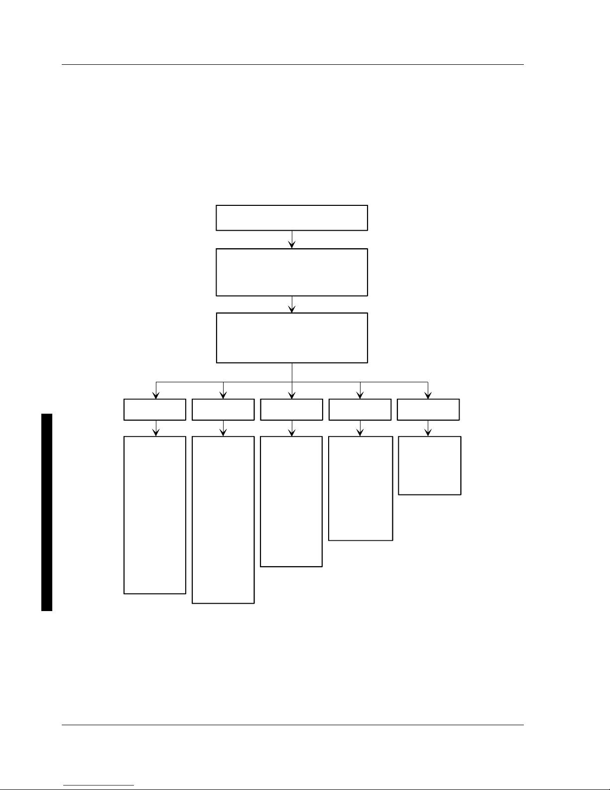
Manoeuvring through Setup
There are five major headings visible on the initial Setup screen. These headings are: Main, Advanced,
Security, Power and Exit. The following illustration shows a partial listing of topics that are available
under each of these headings.
To run the BIOS Setup utility, perform the following steps:
Turn on your computer
When your computer finishes
POST, Select F2
Use the left/right arrow keys to select
one of the headings shown below.
Use the up/down arrow keys to move
through the list of options
MAIN ADVANCED SECURITY POWER EXIT
Enables you
to choose
options such
as:
-Time
-Date
-Language
-Disk drives
-Video
-Cache
-Shadowing
-Boot options
-Keyboard
features
-Memory
Enables you
to choose
options such
as:
-COM ports
-LPT ports
-Diskette
controller
-IDE controller
-Advanced
chipset
control
-SCSI
controller
-Large disk
access mode
-Plug and Play
Enables you
to choose
options such
as:
-Power
management
-IDE hard disk
suspend timer
-Quick
suspend
Enables you
to choose
options such
as:
-Supervisor
and User
passwords
-Sign on
banner
-Backup
reminder
-Virus
reminder
Enables you
to exit Setup
and save
your new
configuration
DEC00664
Figure 2 - 1 BIOS Setup Utility Flow Chart

Digital CELEBRIS XL & XL
DP
PC Utilities & Configuration
MCS Logistics Engineering - Nijmegen 23
Updating The Configuration
The following sections list the BIOS Setup utility options that can be updated or modified using the
following menu selections:
♦ Main Enables to set basic computer configuration options (time, date, video, etc.).
♦ Advanced Enables to set advanced features to increase computer performance (COM ports,
LPT port, etc.).
♦ Security Enables to set passwords and backup data reminders.
♦ Power Enables to set power saving options to save energy.
♦ Exit Enables to quit and save the changes.
NOTE Once a supervisor password is set, a user might not be able to change some BIOS
Setup utility options.
Helpful Hints
Below are some helpful hints when using the BIOS Setup utility:
♦ Several keyboard function keys and numeric keypad keys are assigned to help selecting menus and
sub-menus, options, changing option values and displaying help information. These keys are
displayed at the bottom of the main menu and from the General Help pop-up screen.
♦ Item-specific help is available at anytime during the setup process and appears at the right of the
setup screen each time an option is highlighted. This on-line help provides information about a
highlighted option.
♦ Select “Save Changes & Exit” from the exit menu to save all Setup values.
♦ Select “Discard Changes & Exit” from the exit menu to exit Setup without recording any changes.
♦ Select “Get Default Values” from the exit menu to set all Setup options to their default values.
♦ Select “Load Previous Changes” from the exit menu to restore all CMOS values from the last
session.
♦ Select “Save Changes” from the exit menu to save all selections without exiting Setup.
♦ Press [Esc] to exit a sub-menu and return to the main menu.
♦ Press [Esc] from the main menu to go to the exit menu.

Utilities & C onfiguration Digital C ELEBRIS XL & XLDP PC
24 M C S Logistics Engineering - Nijm egen
Main Menu Options
Menu Fields Settings Comments
System time
Current time Displays the current time.
System date
Current date Displays the current date.
Language
English
Español
Français
Deutsch
Italiano
This field only displays the current language of the BIOS. The setting
in Setup can not be changed. Instead, use PHLASH** to change the
BIOS, where ** is the language extension.
The BIOS Setup utility supports only one language per computer.
Diskette
drive A
Diskette
drive B
1.44MB, 3½
2.88MB, 3½
Not Installed
1.2MB, 5¼
720KB, 3½
Sets the size and density of diskette drives.
Autotype fixed
disk
Press [Enter] Press [Enter] to detect and fill in the installed hard disk drive
parameters in the remaining fields.
Type
(1)
1 to 39
User
Selecting 1 to 39 automatically fills in the remaining fields in this
menu.
Selecting User prompts to fill in the remaining fields with the
installed hard disk drive’s parameters.
(2)
Cylinders
(1)
0 to 4095 Displays the number of cylinders.
Heads
(1)
1 to 64 Displays the number of heads.
Sectors/track
(1
)
0 to 63 Displays the number of sectors/track.
Write
precomp
(1)(2)
0 to 4095
None
Displays the number of cylinders that have their write timing
changed.
Multi-sector
transfers
2 sectors
4 sectors
8 sectors
16 sectors
Auto
Disabled
Determines the number of sectors per block for multiple sector
transfers.
Auto refers to the size the disk returns when queried.
LBA control
mode
Disabled
Enabled
Enables or disables the LBA hard disk drive addressing option.
Video system
EGA / VGA
CGA 80x25
Monochrome
Sets the video controller type.
(1)
These fields are automatically filled in if the computer auto-detected an installed hard disk drive.
(2)
Incorrect settings can cause the computer to malfunction.

Digital CELEBRIS XL & XL
DP
PC Utilities & Configuration
MCS Logistics Engineering - Nijmegen 25
Memory and Cache Options
Menu Fields Settings Comments
Internal cache
Enabled
Disabled
Enables or disables the internal cache.
Note: The internal cache is internal to the CPU.
External
cache
Enable (WB)
Enable (WT)
Disable
The external cache operates in Write-Back (WB) Mode if Enable has
been selected.
The external cache operates in Write-Through (WT) Mode if Enable
has been selected.
For optimal computer performance, keep this setting at Enabled
(WB).
System BIOS
shadow
Not user
selectable,
permanently set
to Enabled.
The main logic board reserves an area of DRAM for a copy of system
BIOS ROM. This DRAM called "shadow memory" is write-protected
and has the same addresses as the system BIOS ROM locations.
When shadowing system BIOS ROM, the ROM information is copied
into an appropriate area in DRAM. This increases the performance
because the system BIOS instructions are in fast DRAM instead of
ROM.
Cache system
BIOS
Enabled
Disabled
This option enables the system BIOS to be cached in the internal
cache and external cache (if installed). This increases computer
performance because BIOS instructions can be executed in cache
instead of RAM.
Video BIOS
shadow
Enabled
Disabled
The main logic board reserves an area of DRAM for a copy of video
BIOS ROM. This DRAM called "shadow memory" is write-protected
and has the same addresses as the video BIOS ROM locations. When
shadowing video BIOS ROM, the ROM information is copied into an
appropriate area in DRAM. This increases the performance because
the video BIOS instructions are in fast DRAM instead of ROM.
Cache video
BIOS
Enabled
Disabled
This option enables the video BIOS to be cached in the internal cache
and external cache (if installed). This increases computer
performance as video BIOS instructions can be executed in cache
instead of RAM.
Shadow
option ROM’s
C800-CBFF
CC00-CFFF
D000-D3FF
D400-D7FF
D800-DBFF
DC00-DFFF
Enabled
Disabled
Allows to enable or disable shadowing of individual segments of
ROM to increase computer performance.
Caution: Some option ROMs do not operate properly when
shadowed.

Utilities & C onfiguration Digital C ELEBRIS XL & XLDP PC
26 M C S Logistics Engineering - Nijm egen
AT bus space
Disabled
C00000h,
4MB
E00000h,
2MB
F00000h,
1MB
Memory hole not available, upper memory is contiguous.
Sets the memory hole at address C00000 with 4MB memory
available.
Sets the memory hole at address E00000 with 2MB memory
available.
Sets the memory hole at address F00000 with 1MB memory available.
System
memory
Not user
selectable
Displays the amount of base (conventional) memory each time the
computer boots.
Extended
memory
Not user
selectable
Displays the amount of extended memory each time the computer
boots.

Digital CELEBRIS XL & XL
DP
PC Utilities & Configuration
MCS Logistics Engineering - Nijmegen 27
Memory and Cache Options (continued)
Menu Fields Settings Comments
Extended
memory
report
Compatibility
Noncompatibility
Selects the BIOS report mechanism for memory amount.
Select Compatibility when using a conventional operating system.
Select Non-Compatibility for extended memory above 64MB under
Windows NT V3.1.
Boot Options
Menu Fields Settings Comments
Boot sequence
A: only
A: then C:
C: then A:
C: only
Each time the computer boots, it will load the operating system from
the selected sequence.
SETUP
prompt
Enabled
Disabled
Enables or disables the <F2> setup prompt each time the computer
boots.
When Disabled is selected, only the prompt informing you when to
press <F2> to enter Setup is disabled. Setup can still be entered by
pressing <F2> before POST completes.
POST errors
Enabled
Disabled
Enabling this options causes the computer to pause and display a
setup entry or resume the boot prompt if an error occurs at boot.
Disabling this option causes the computer to always attempt to boot
regardless of a setup entry or error.
Floppy check
Enabled
Disabled
Enabling this option causes the computer to verify the diskette type
each time the computer boots.
Disabling this option speeds up the boot process.
Summary
screen
Enabled
Disabled
Enabling this option causes the computer to display configuration
parameters (in the form of a summary screen) during boot.

Utilities & C onfiguration Digital C ELEBRIS XL & XLDP PC
28 M C S Logistics Engineering - Nijm egen
Keyboard Features
Menu Fields Settings Comments
Numlock
Auto
On
Off
Turns Numlock on or off each time the computer boots.
Note: When Auto has been selected, the computer will turn on
Numlock if it detects a numeric keypad.
Key click
Disabled
Enabled
Enables or disables the audible key click feature.
Keyboard
auto-repeat
rate
30/sec
2/sec
6/sec
10/sec
13.3/sec
18.5/sec
21.8/sec
26.7/sec
Sets the number of times a second to repeat a keystroke while holding
the key down.
Keyboard
auto-repeat
delay
1/2 sec
3/4 sec
1 sec
1/4 sec
Sets the delay time after a key is held down before it begins to repeat
a keystroke.
Integrated Peripherals
Menu Fields Settings Comments
Mouse port
Disabled
Enabled
Enables or disables the mouse port.
Parallel port
Auto
Disabled
3BC, IRQ 7
378, IRQ 7
278, IRQ 5
Enables or disables the onboard port at the specified address.
Note: Two devices cannot share the same IRQ. Also, choosing
disable makes the parallel port unusable.
Diskette
controller
Enabled
Disabled
Enables or disables the onboard diskette controller.
Exchange
diskette drives
Disabled
Enabled
Enables to logically exchange physical diskette drive designations.

Digital CELEBRIS XL & XL
DP
PC Utilities & Configuration
MCS Logistics Engineering - Nijmegen 29
Integrated Peripherals (continued)
Menu Fields Settings Comments
Diskette write
protection
Disabled
Enabled
Enables or disables the selected diskette drive’s write protect option.
Parallel port
mode
Compatible
mode
Bi-directional
mode
ECP mode
EPP 1.7
EPP 1.9
Standard printer connection.
PS/2 compatible mode and able to receive data.
Extended capabilities port mode.
Enhanced parallel port mode.
Selection based on what EPP version the printer supports.
Only choose a mode that the parallel port device (such as a printer)
supports. Check the parallel port device documentation for this
information.
Serial port 1
Auto
Disabled
3F8, IRQ 4
2F8, IRQ 3
3E8, IRQ4
2E8, IRQ3
Enables or disables onboard serial port 1 at the specified address.
Select Auto unless interrupts IRQ4 and/or IRQ3 have been allocated
as a computer resource.
Two devices cannot share the same IRQ. Choosing Disable makes
serial port 1 unusable. When selecting Auto, setup configures COM1
to address = 3F8h and IRQ = 4.
Serial port 2
Auto
Disabled
3F8, IRQ 4
2F8, IRQ 3
3E8, IRQ4
2E8, IRQ3
Enables or disables onboard serial port 2 at the specified address.
Select Auto unless having interrupts IRQ4 and/or IRQ3 allocated as a
computer resource.
Two devices cannot share the same IRQ. Choosing Disable makes
serial port 2 unusable. When Auto has been selected, setup
configures COM2 to address = 2F8h and IRQ = 3.
IDE controller
Enabled
Disabled
Enables or disables the onboard IDE controller.
On-board
SCSI device
Enabled
Disabled
Enables or disables the onboard PCI SCSI device.
External SCSI
device
Disabled
Enabled
Enables or disables the main logic board's external SCSI port.

Utilities & C onfiguration Digital C ELEBRIS XL & XLDP PC
30 M C S Logistics Engineering - Nijm egen
Advanced Chipset Control Options
NOTE The following advanced chipset control options should normally stay at their default
values.
Menu Fields Settings Comments
CPU to PCI
write buffers
Disabled
Enabled
Enables or disables the CPU to PCI write buffers.
These buffers enable data to be temporarily stored before writing the
data.
VGA palette
snoop
Enabled
Disabled
Default
This option controls how VGA devices handle accesses to their palette
areas. Enabling this option causes special palette behavior (a device
must not respond to normal accesses). Disabling this option causes a
device to treat palette accesses like any other device access.
Enable VGA Palette Snoop when a second video adapter is connected
to the feature connector of the installed VGA adapter for multi-media
devices.
PCI parity
Enabled
Disabled
Enables or disables the parity checking feature of the PCI bus.
Enabled gives higher reliability on PCI bus transfers. Disabled may
be required for some PCI options that do not properly support this PCI
feature.
PCI arbiter
priority
(1)
System default
Pure rotating
ISA slot
Onboard SCSI
CPU
PCI slot 1
PCI slot 2
PCI slot 3
Use the BIOS default value. BIOS will select optimal settings based
on the current computer hardware configuration.
The priority rotates for all PCI devices.
ISA slot has the highest priority.
Onboard SCSI has the highest priority.
CPU has the highest priority.
PCI slot 1 has the highest priority.
PCI slot 2 has the highest priority.
PCI slot 3 has the highest priority.
On-board
SCSI latency
timer
40h, 48h
50h, 58h
60h, 68h
70h, 78h
80h, 88h
90h, 98h
A0h, A8h
B0h, B8h
C0h, C8h
D0h, D8h
E0h, E8h
F0h, F8h
Default
08h, 10h
18h
20h, 28h
30h, 38h
Each PCI device has a latency timer register. This register specifies,
in PCI clocks, the value of the latency timer for a particular PCI
device master.
 Loading...