

Digital Equipment CELEBRIS Pentium PC, CELEBRIS 560, CELEBRIS 590, CELEBRIS 575, CELEBRIS 590FP Service Maintenance Manual
...
Service
Maintenance
Manual
CELEBRIS Pentium
PC
EK-A0822-SV. A01
Copyright Digital Equipment Corporation
All rights reserved

November 1995
November 1995
The information in this document is subject to change without notice and should not be construed as a
commitment by Digital Equipment Corporation.
Digital Equipment Corporation assumes no responsibility for any errors that might appear in this
document.
The software, if any, described in this document is furnished under a license and may be used or copied
only in accordance with the terms of such license. No responsibility is assumed for the use or reliability of
software or equipment that is not supplied by Digital Equipment Corporation or its affiliated companies.
Restricted Rights: Use, duplication, or disclosure by the U.S. Government is subject to restrictions as set
forth in subparagraph (c) (1) (ii) of the Rights in Technical Data and Computer Software clause at DFARS
252.227-7013.
Copyright Digital Equipment Corporation
All Rights Reserved
The following are trademarks of Digital Equipment Corporation:
CELEBRIS and the Digital logo.
The following are third party trademarks:
MS-DOS and Windows and Windows NT and Windows NT Server are trademarks of Microsoft Corp.
Novell and Netware are trademarks of Novell, Inc.
SCO and Open Desktop are trademarks of The Santa Cruz Operation, Inc.
UNIX is a registered trademark of UNIX System Laboratories, Inc.
All other trademarks and registered trademarks are the property of their respective holders.
Created by:
MCS Logistics Engineering - Nijmegen
Printed in Ireland

Digital CELEBRIS Pentium PC Table of Contents
MCS Logistics Engineering - Nijmegen 3
Table of Contents
PREFACE ....................................................................................................................................................7
CHAPTER 1 PRODUCT DESCRIPTION..............................................................................................9
P
RODUCT INTRODUCTION...............................................................................................................................9
P
RODUCT MODELS INFORMATION................................................................................................................10
CELEBRIS Pentium Models...................................................................................................................10
CHAPTER 2 SYSTEM UTILITIES & CONFIGURATION...............................................................11
S
YSTEM UTILITIES........................................................................................................................................11
Before Using System Utilities and Video Drivers...................................................................................11
PHLASH.EXE........................................................................................................................................12
Creating a Crisis Recovery Diskette .......................................................................................................12
Using the Crisis Recovery Diskette.........................................................................................................13
Upgrading the computer BIOS................................................................................................................13
EPP3SMC.EXE ......................................................................................................................................15
V
IDEO DRIVERS & UTILITIES........................................................................................................................15
Setting High Resolution Mode for The Monitor Display........................................................................15
SMODE.EXE..........................................................................................................................................15
SMTR.EXE.............................................................................................................................................16
DOS Video Drivers.................................................................................................................................17
Windows 3.x Drivers..............................................................................................................................17
BIOS S
ETUP UTILITY ...................................................................................................................................17
Running the BIOS Setup Utility .............................................................................................................18
Helpful Hints...........................................................................................................................................18
BIOS S
ETUP UTILITY OPTIONS.....................................................................................................................19
Main Menu Options................................................................................................................................19
Boot Options...........................................................................................................................................19
Fixed Disk Setup Options.......................................................................................................................21
Keyboard Features..................................................................................................................................22
Memory and Cache Options ...................................................................................................................22
Advanced Chip Set Control ....................................................................................................................23
Integrated Peripherals..............................................................................................................................23
Large Disk Access Mode........................................................................................................................25
Power Options.........................................................................................................................................25
Security Options .....................................................................................................................................26
CHAPTER 3 SERVICE PROCEDURES..............................................................................................27
S
AFETY REQUIREMENTS...............................................................................................................................27
R
ECOMMENDED TOOLS................................................................................................................................28
Other Materials Needed..........................................................................................................................28
Special Tools Required...........................................................................................................................28
Remedial Diagnostic Test Software........................................................................................................28
Recommended Virus Detection and Cleanup Software ..........................................................................28
ECO/FCO I
NFORMATION.............................................................................................................................29

Table of C ontents Digital CELEBRIS Pentium PC
4 M C S Logistics Engineering - N ijm egen
BIOS Version Information..................................................................................................................... 29
U
NLOCKING AND REMOVING COVER........................................................................................................... 30

Digital CELEBRIS Pentium PC Table of Contents
MCS Logistics Engineering - Nijmegen 5
COMPUTER COMPONENTS ............................................................................................................................31
CELEBRIS Pentium Low-Profile Models...............................................................................................31
CELEBRIS Pentium Full-Profile Models................................................................................................32
E
XPANSION SLOTS........................................................................................................................................33
CELEBRIS Pentium Low-Profile Expansion Slots.................................................................................33
CELEBRIS Pentium Full-Profile Expansion Slots..................................................................................35
M
AIN LOGIC BOARD JUMPERS......................................................................................................................37
CELEBRIS Pentium Main Logic Board Jumper Settings.......................................................................37
CELEBRIS Pentium Main Logic Board Jumper Locations....................................................................38
C
OMPUTER MEMORY CONFIGURATIONS ......................................................................................................39
CELEBRIS Pentium SIMM Socket Locations........................................................................................40
P
ART REMOVAL AND REPLACEMENT............................................................................................................42
Opening the Low-Profile Device Bay & Power Supply Subassembly.....................................................42
Opening the Full-Profile Device Bay & Power Supply Subassembly.....................................................44
Removing the 3½-Inch Diskette Drive (Low-Profile Models)................................................................45
Removing the 3½-Inch Diskette Drive (Full-Profile Models).................................................................46
Removing the Main Logic Board............................................................................................................48
Removing the Power Supply (Low-Profile Models)................................................................................49
Removing the Riser Card & Bracket.......................................................................................................51
I
NSTALLATION PROCEDURES........................................................................................................................53
Installing a Higher Performance CPU.....................................................................................................53
Installing External Cache Memory..........................................................................................................55
Installing Video Memory........................................................................................................................57
R
EPLACEMENT PROCEDURES........................................................................................................................58
Replacing the Computer Battery.............................................................................................................58
C
ONNECTING DISKETTE AND IDE DEVICES..................................................................................................60
Connecting Diskette Devices..................................................................................................................60
Connecting IDE Devices.........................................................................................................................62
CHAPTER 4 TROUBLESHOOTING...................................................................................................63
I
NITIAL TROUBLESHOOTING .........................................................................................................................63
B
EEP CODES.................................................................................................................................................64
POST
AND BOOT MESSAGES........................................................................................................................64
C
OMPUTER TROUBLESHOOTING...................................................................................................................67
Disk Drive Troubleshooting....................................................................................................................73
Monitor Troubleshooting........................................................................................................................74
QAPlus/FE Error Messages.....................................................................................................................75
CHAPTER 5 DEVICE MAPPING.........................................................................................................77
CPU Memory Address Map (Full Range)...............................................................................................77
CPU I/O Address Map............................................................................................................................77
I/O Address Map.....................................................................................................................................78
Computer Interrupt Levels......................................................................................................................79
DMA Channel Assignment.....................................................................................................................79
PCI Configure Space Address Map.........................................................................................................79
CHAPTER 6 PASS / FAIL CRITERIA.................................................................................................81
APPENDIX A SERVICE NOTES..........................................................................................................83

Table of C ontents Digital CELEBRIS Pentium PC
6 M C S Logistics Engineering - N ijm egen
APPENDIX B USEFUL INFORMATION............................................................................................ 85
R
ELATED DOCUMENTATION........................................................................................................................ 85
O
N-LINE BULLETIN BOARDS........................................................................................................................ 86
DOCUMENT FEEDBACK...................................................................................................................... 87
PERSONAL NOTES................................................................................................................................. 89
R
EADERS COMMENTS..................................................................................................................................93
Table of Figures
Figure 3 - 1 Unlocking the Cover............................................................................................................... 30
Figure 3 - 2 Release the Cover................................................................................................................... 30
Figure 3 - 3 Removing the Cover............................................................................................................... 30
Figure 3 - 4 CELEBRIS Pentium Low-Profile models............................................................................... 31
Figure 3 - 5 CELEBRIS Pentium Full-Profile models................................................................................ 32
Figure 3 - 6 CELEBRIS Pentium Low-Profile Models Expansion slots.....................................................34
Figure 3 - 7 CELEBRIS Pentium Full-Profile Models Expansion slots..................................................... 36
Figure 3 - 8 CELEBRIS Pentium Main Logic Board Jumper Locations....................................................38
Figure 3 - 9 CELEBRIS Pentium SIMM Socket Locations........................................................................ 41
Figure 3 - 10 Release Front Locking Mechanism....................................................................................... 42
Figure 3 - 11 Lock in place ........................................................................................................................ 43
Figure 3 - 12 Opening the Full-Profile Device bay & Power Supply Assembly......................................... 44
Figure 3 - 13 Removing the 3½-inch diskette drive (Low-Profile Models)................................................ 45
Figure 3 - 14 Removing the 3½-Inch Diskette Drive (Full-Profile Models)............................................... 47
Figure 3 - 15 Removing the Mian Logic Board.......................................................................................... 48
Figure 3 - 16 Releasing the Latch............................................................................................................... 49
Figure 3 - 17 Removing the Low-Profile Models Power Supply.............................................................. 49
Figure 3 - 18 Removing the Full-Profile Models Power Supply................................................................. 50
Figure 3 - 19 Removing the Riser Card & Bracket (Low-Profile Models)................................................. 51
Figure 3 - 20 Removing the Riser Card & Bracket (Full-Profile Models).................................................. 52
Figure 3 - 21 Installing a Higher Performance CPU................................................................................... 54
Figure 3 - 22 Installing External Cache Memory....................................................................................... 56
Figure 3 - 23 Installing Video Memory...................................................................................................... 57
Figure 3 - 24 Replacing the computer’s Battery.........................................................................................59
Figure 3 - 25 Diskette Drive Connection....................................................................................................61
Figure 3 - 26 IDE Drive Connection.......................................................................................................... 62

Digital CELEBRIS Pentium PC Preface
MCS Logistics Engineering - Nijmegen 7
Preface
The Digital CELEBRIS Pentium Service Maintenance Manual is a troubleshooting guide that can be used
for reference when servicing the CELEBRIS Pentium line of PC’s.
Digital Equipment Corporation reserves the right to make changes to the Digital CELEBRIS Pentium
series without notice. Accordingly, the diagrams and procedures in this document may not apply to the
computer(s) to be serviced since many of the diagnostic tests are designed to test more than one product.
CAUTION
Digital recommends that only A+ certified engineers attempt to repair this equipment.
All troubleshooting and repair procedures are detailed to support subassembly/module
level exchange. Because of the complexity of the indivual boards and subassemblies, no
one should attempt to make repairs at component level or to make modifications to any
printed wiring board. Improper repairs can create a safety hazard. Any indications of
component replacement or printed wiring board modifications may void warranty or
exchange allowances.


Digital CELEBRIS Pentium PC Product Description
MCS Logistics Engineering - Nijmegen 9
Chapter 1 Product Description
Product Introduction
Digital CELEBRIS Pentium computers are high-performance personal computers equipped with the latest
computing technology. They can be used as standalone computers , as client, or as servers in a network
environment. Developed using state-of-the-art technology, these computers are the most value-packed
desktop computers in their class. The following models are currently available:
♦ CELEBRIS 560 low-profile enclosure with 60 MHz Pentium
♦ CELEBRIS 575 low-profile enclosure with 75 MHz Pentium
♦ CELEBRIS 590 low-profile enclosure with 90 MHz Pentium
♦ CELEBRIS 590 FP full profile enclosure with 90 MHz Pentium
♦ CELEBRIS 5100 low-profile enclosure with 100 MHz Pentium
♦ CELEBRIS 5100 FP full-profile enclosure with 100 MHz Pentium
Significant features include:
♦ PCI local bus technology
♦ ZIF (Zero Insertion Force) socket 2 x ZIF 4 and 5
♦ 8MB system RAM, expandable to 128 MB
♦ 4 SIMM sockets for memory upgrade
♦ 256KB external Cache up to 512KB
♦ Plug and Play
♦ On-board FDU controller
♦ On-board Enhanced local bus IDE up to four devices
♦ One PCI, One ISA, one PCI/ISA interleaved, Full Profile models have 2 more ISA slots
♦ Advanced PCI S3 864 video controller, 1MB DRAM upgradable to 2MB
♦ Flash BIOS
♦ Screwless design
♦ “Energy Star” compliant (30 Watt or less EPA requirement)

Product Description Digital CELEBRIS Pentium PC
10 M C S Logistics Engineering - N ijm egen
Product Models Information
EC = English, French, German, Italian and Spanish.
ED = Danish, Dutch, English, Finnish, French (France excluded), Norwegian and Swedish.
CELEBRIS Pentium Models
Product Model FDD HDD Memory Cache Options
CELEBRIS 560
FR-830WW-AC 1.44MB - 8MB 256KB
FR-830E*-WB 1.44MB 270MB 8MB 256KB
FR-830E*-WC 1.44MB 540MB 8MB 256KB
CELEBRIS 590
FR-832WW-AC 1.44MB - 8MB 256KB
FR-832E*-WB 1.44MB 270MB 8MB 256KB
FR-832E*-WC 1.44MB 540MB 8MB 256KB
FR-832E*-WD 1.44MB 840MB 16MB 256KB
CELEBRIS 575
FR-833WW-AC 1.44MB - 8MB 256KB
FR-833E*-WB 1.44MB 270MB 8MB 256KB
FR-833E*-WC 1.44MB 540MB 8MB 256KB
FR-833E*-WD 1.44MB 540MB 16MB 256KB
CELEBRIS 590FP
FR-842WW-AC 1.44MB - 8MB 256KB
FR-842E*-WB 1.44MB 270MB 8MB 256KB
FR-842E*-WC 1.44MB 540MB 8MB 256KB
FR-842E*-WD 1.44MB 540MB 16MB 256KB
CELEBRIS 5100
FR-834WW-AC 1.44MB - 8MB 256KB
FR-834E*-WD 1.44MB 540MB 16MB 256KB
CELEBRIS 5100FP
FR-844WW-AC 1.44MB - 16MB 256KB
FR-844E*-WD 1.44MB 5400MB 16MB 256KB

Digital CELEBRIS Pentium PC Utilities & Configuration
MCS Logistics Engineering - Nijmegen 11
Chapter 2 System Utilities &
Configuration
System Utilities
This chapter describes how to use the utilities and video drivers supplied with the CELEBIS Pentium
computer. In most cases, these utilities and drivers have been factory installed as image files on the hard
disk drive. However, before attempting to use any of the utilities or install any of the video drivers, first
copy all image files onto diskettes using the Create Installation Diskettes tool in Getting Started.
Afterwards, use these diskettes to run any of the utility programs and/or to install drivers.
When utilities and video driver diskettes have been purchased, refer to the supplied MS-DOS/Windows
documentation for information on creating back-up diskettes.
System utilities consist of the following:
♦ PHLASH.EXE − enables to upgrade or restore the computer’s BIOS via Flash ROM.
♦ EPP3SMC.EXE − enables to configure the computer for EPP operation.
♦ Logitech mouse drivers − enables the computer to operate using a Logitech mouse.
♦ VGA utilities and DOS video drivers consisting of:
◊ SMTR.EXE − enables to select the monitor type that matches the monitor’s available resolution
and refresh rates.
◊ SMODE.EXE - enables to emulate or display non-standard VGA modes.
◊ DOS and CAD application video drivers− provide installation instructions and, where
applicable, the usage and performance tips for several S3 Trio 32 (86C732-P) video drivers.
◊ README.TXT - contains information on the display drivers and instructions for configuring
the computer to operate with a high resolution monitor.
◊ Windows 3.x video drivers:
These files consist of S3 Trio 32 (86C732-P) video drivers.
Before Using System Utilities and Video Drivers
When unfamiliar with utility programs, video drivers, and their uses, carefully read and understand this
chapter before attempting to use any of the utilities or installing video drivers.

Utilities & C onfiguration Digital CELEBRIS Pentium PC
12 M C S Logistics Engineering - N ijm egen
PHLASH.EXE
All computers have BIOS software in a read-only, non-volatile memory (ROM) chip. This BIOS initializes
hardware and boots the operating system when the computer is turned on. The BIOS also provides access
to other services such as keyboard and disk drives.
The computer comes equipped with flash memory. This means the computer’s BIOS can be restored
simply by running the PHLASH.EXE utility contained on the supplied System Utilities diskette. The
computer’s BIOS can also be upgraded to future releases by running PHLASH.EXE along with any flash
BIOS update diskette if necessary.
CAUTION
When not familiar with utility programs and their uses, carefully read and understand
all of the listed topics before attempting to use PHLASH.EXE.
Have the following items available:
♦ Blank 3½-inch 1.44 MB formatted diskette
♦ Diskette copy of the system utilities
Creating a Crisis Recovery Diskette
A crisis recovery diskette should always be prepared before attempting to upgrade the BIOS. This diskette
is used to reprogram the BIOS in case the flash process fails. To create a crisis recovery diskette:
1) Turn on the computer and allow the POST to complete. If POST detects an error refer to
“Troubleshooting” and take the appropriate steps to correct the problem. After the problem has been
resolved, restart the computer.
2) Insert the system utilities diskette that have been created from Getting Started and make sure the
following files are in the UPGRADE directory:
MINIDOS.SYS
PHLASH.EXE
DEVTBLS.DAT
PHLASH.INI
CELEBRIS.ROM
MAKEBOOT.EXE
MAKECRD.EXE
NOTE This diskette also contains multilingual BIOS files that can be used to change the
language type in Setup.
3) Create the same directory on the hard disk drive and then copy the above files to it.
4) Insert a blank formatted diskette into drive A.
5) On drive A, make a directory for the files previously copied.
6) From drive C: type
1%/)'6(
. This copies the files to drive A.
7) Remove the crisis recovery diskette from drive A and store it in a safe place.

Digital CELEBRIS Pentium PC Utilities & Configuration
MCS Logistics Engineering - Nijmegen 13
Using the Crisis Recovery Diskette
The crisis recovery diskette must be used only if the computer’s BIOS fails or if a BIOS upgrade was
unsuccessful.
♦ POST detects an error after a normal boot cycle or a BIOS upgrade.
♦ The BIOS in the bootblock memory executes.
♦ The computer beeps several times.
♦ The diskette drive begins searching for the crisis recovery diskette.
If the computer’s BIOS fails:
1) Set the recovery jumper (J25) to enabled.
2) Insert the crisis recovery diskette into drive A and power on the computer.
3) After the BIOS is restarted, turn off the power and remove the crisis recovery diskette from drive A.
4) Turn the power back on for normal operation.
Upgrading the computer BIOS
These utilities and video drivers enable to upgrade or restore the computer’s BIOS and take full advantage
of its enhanced video features.
NOTE If this is the first time using these utility programs and/or video drivers it is
recommended to follow the procedures in the order given.
1) Turn on or reboot the computer. If POST detects an error, refer to “Troubleshooting” for possible
causes and suggested solutions.
2) If necessary, run PHLASH.EXE to upgrade or restore the computer’s BIOS.
3) Run EPP3SMC.EXE to configure the computer for EPP operation.
4) Run SMTR.EXE to select the monitor type that matches the monitor’s available resolution and
refresh rates.
5) If necessary, run SMODE.EXE to emulate or display a non-standard VGA mode.
6) Install any applicable DOS or CAD application drivers.
7) Install any Windows 3.x video drivers.
Perform the following steps to update the computer’s BIOS in flash memory:
1) Turn on the computer and allow the POST to complete. If the POST detects an error refer to
“Troubleshooting” and take the appropriate steps to correct the problem. After the problem has been
resolved, restart the computer.
2) Create a crisis recovery diskette if not already done so.
Refer to “Creating a Crisis Recovery Diskette”.
3) Insert the system utilities diskette.
4) At the MS-DOS prompt, enter the following commands (press [Enter] after each command):
a:
cd\UPGRADE
PHLASH /e

Utilities & C onfiguration Digital CELEBRIS Pentium PC
14 M C S Logistics Engineering - N ijm egen
A screen appears on the monitor warning that you are about to erase the computer’s BIOS.

Digital CELEBRIS Pentium PC Utilities & Configuration
MCS Logistics Engineering - Nijmegen 15
5) Press [Enter] to continue. Else, press [Esc] to cancel.
Once [Enter] has been pressed, PHLASH.EXE automatically updates the computer’s BIOS.
After the flashing process completes, the computer automatically reboots itself so changes
immediately take effect.
6) Remove the system utilities diskette.
EPP3SMC.EXE
EPP3SMC.EXE can be executed as an MS-DOS command or added to the CONFIG.SYS file as a device
driver. In either case, use the BIOS Setup utility to set the parallel port to EPP mode.
Video Drivers & Utilities
The following topics describe how to use the video utilities and install video drivers on the computer:
SMODE.EXE
SMTR.EXE
DOS Video Drivers
Windows 3.x Drivers
Setting High Resolution Mode for The Monitor Display
To use the high resolution modes on the computer, perform the following steps:
1) Use the BIOS Setup utility to set correctly the Video System option.
2) Use SMTR.EXE from the VGA Utilities and DOS Video Drivers diskette to set correctly a Monitor
Type.
3) Use Windows Setup to copy the appropriate video driver into Windows.
CAUTION
Do not connect a low resolution monitor to a system that has been configured with
high-resolution video drivers.
High resolution drivers can damage a 640 x 480 monitor.
SMODE.EXE
The SMODE utility allows the main logic board’s video circuitry to emulate and display non-standard
VGA modes. With SMODE, you can run software applications written for the following non-VGA modes:
♦ Monochrome adapter (MDA)
♦ Color graphics adapter (CGA)
♦ Expanded graphics adapter (EGA)
♦ Hercules monochrome graphics adapter (HGC)
Utilities & C onfiguration Digital CELEBRIS Pentium PC
16 M C S Logistics Engineering - N ijm egen
The following procedure describes how to access SMODE:
1) Turn on or reboot the computer and allow the POST to complete.
2) Insert the VGA Utilities and DOS Video Drivers diskette into drive A.
3) Type A:
then press [Enter].
4) Type CD\UTILS
and press [Enter].
5) Run the SMODE.EXE utility following the instructions on the monitor screen.
If you want to Type SMODE followed by Example
Display a non-standard VGA
mode
<hex mode #> VGA SMODE 55 VGA
Emulate a non-VGA mode Either EGA, CGA, MDA, or Hercules SMODE MDA
NOTE VGA modes and corresponding hexadecimal numbers are listed in the release notes
supplied with the computer. SMODE MDA allows the main logic board’s video
circuitry to emulate a monochrome adapter
SMTR.EXE
The video controller’s monitor type selection must match the monitor’s available resolution and refresh
rates. These monitor resolution and refresh rates are listed in the monitor’s support documentation and in
the SMTR.EXE utility.
CAUTION
Do not select a monitor type setting that exceeds the monitor’s resolution, refresh rate
(vertical synchronization), and interlace or non-interlace specifications. Refer to the
monitor’s support documentation for performance specifications.
To select the correct monitor type:
1) Turn on or reboot the computer and allow POST to complete.
2) Insert the VGA Utilities and DOS Video Drivers diskette into drive A.
3) Type A:
then press [Enter].
4) Type CD\UTILS and press [Enter].
5) Type SMTR and press [Enter].
6) Select the correct monitor type following the instructions on the monitor screen.
For example, if you want to run the monitor at a resolution of 1024 × 768, select
1024x768@70Hz/NI.
7) Exit the SMTR.EXE utility following the instructions on the monitor screen.
Digital CELEBRIS Pentium PC Utilities & Configuration
MCS Logistics Engineering - Nijmegen 17
DOS Video Drivers
These files contain installation instructions and, where applicable, the usage and performance tips for
various DOS and CAD applications.
Installing DOS or CAD application video drivers differ with each software application. Specific
instructions are located in the README.TXT file and in the appropriate DOS or CAD application
directories and files.
Windows 3.x Drivers
These files contain the available S3 Trio 32 (86C732-P) video drivers for Windows 3.x. Depending on
how the computer is configured and what software applications planned to be used, it may be necessary to
install one or more of these drivers to optimize the capabilities of the computer.
Before installing a video device driver, read and understand the information in any associated README
file.
To install a Windows 3.x video driver, perform the following:
1) Type CD WINDOWS at the C:\>
prompt, then press [Enter].
The following prompt appears: C:\WINDOWS>.
2) Type SETUP and press [Enter].
The computer displays the SETUP screen.
3) Select the
(MWTPE]
option and press [Enter].
4) Toggle through the
(MWTPE]
option to select the appropriate Windows 3.x driver.
5) Select the desired video resolution then press [Enter].
6) If the appropriate video driver resides on a separate diskette, toggle through the
(MWTPE]
option to
select
3XLIV
(Requires disk provided by hardware manufacturer).
7) Insert the diskette that contains the appropriate video driver and press [Enter].
8) Select the desired video resolution then press [Enter].
NOTE The resolution and refresh rate must be the same as the selection made using the
SMTR.EXE utility. The video setup screen appears again with the S3 driver.
9) Press [Enter] to accept the configuration.
The MS-DOS prompt appears when SETUP completes.
10) Type WIN and press [Enter] to start Microsoft Windows.
BIOS Setup Utility
The information listed below explains how to configure the computer using the BIOS Setup utility. If the
computer was delivered with factory-installed software, it has already been configured.
When familiar with utility programs and their uses, refer to the material in the options table while updating
the computer. Otherwise, carefully read and understand all the information in this chapter before
attempting to modify the computer’s configuration settings.

Utilities & C onfiguration Digital CELEBRIS Pentium PC
18 M C S Logistics Engineering - N ijm egen
Running the BIOS Setup Utility
The BIOS Setup utility enables to select and permanently store information about the computer’s hardware
and software in the battery-backed memory of the CMOS RAM. This information takes effect each time
the computer boots and can be changed each time you run setup.
Use the BIOS Setup utility when experiencing problems with the hard disk or need to reconfigure the
computer. In addition, the BIOS Setup utility might need to be used to modify the configuration after
adding or removing hardware, or after changing computer settings.
To run the BIOS Setup utility:
1) Turn on the computer and allow POST to complete.
2) Make a note of any configuration errors listed, and then press [F2] to display the main menu.
3) Follow the instructions on screen and any on-line help pop-up screens to configure the computer.
Helpful Hints
♦ Several keyboard function keys and numeric keypad keys are assigned to help select menus and
options, change option values, and display help information. These keys are displayed at the bottom
of the main menu and from the General Help pop-up screen.
♦ Item-specific help is available anytime during the setup process and appears at the right of the setup
screen each time an option is highlighted. This on-line help provides information about a highlighted
option.
♦ Select "Save Changes & Exit" to save all Setup values.
♦ Select "Discard Changes & Exit" to exit Setup without recording any changes.
♦ Select "Get Default Values" to set all Setup options to their default values.
♦ Select "Load Previous Changes" to restore all CMOS values from the last session.
♦ Select "Save Changes" to save all selections without exiting Setup.
♦ Press [Esc] to exit the Setup utility.
Digital CELEBRIS Pentium PC Utilities & Configuration
MCS Logistics Engineering - Nijmegen 19
BIOS Setup Utility Options
Specific notes pertaining to some Setup options may be obtained by clicking on colored entries in the
"Menu Field" column described below, and/or by clicking on the icons in the rightmost column.
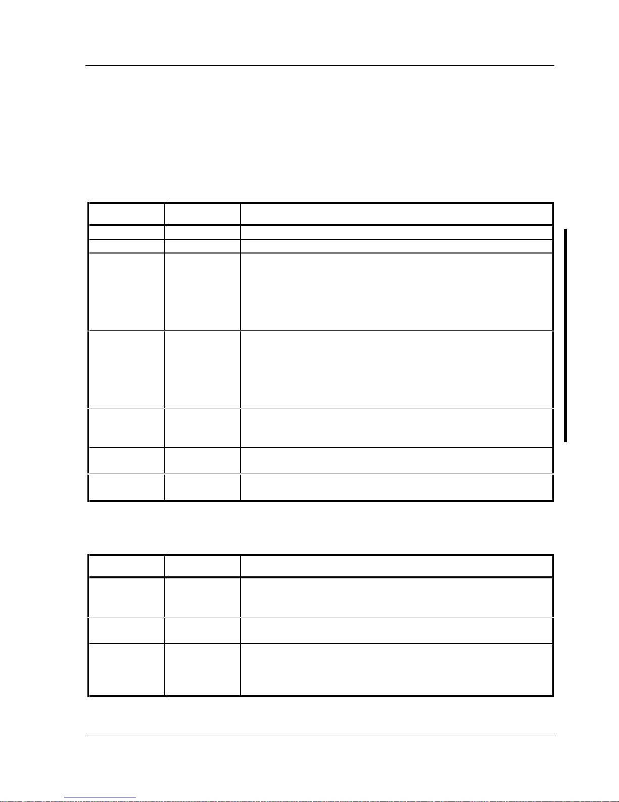
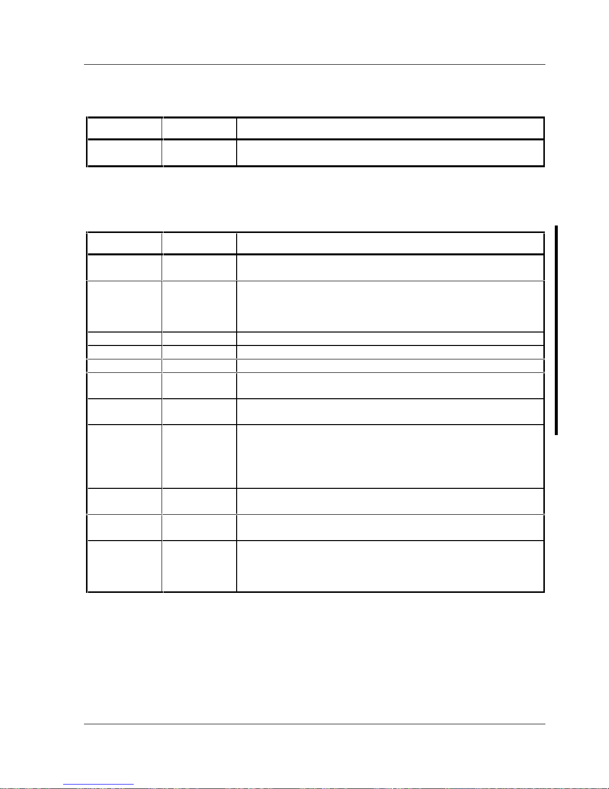
Main Menu Options
Menu Field Settings Comments
System time
Current time Displays the current time.
System date
Current date Displays the current date.
Language
English
Español
Français
Deutsch
Italiano
The system utilities diskette contains all the languages listed as
possible settings. Use the PHLASH.EXE program and the desired
language BIOS file to load a different language. The BIOS Setup
utility choices are English and one other language. For example,
English and French, English and German, depending on the language
kit that has been ordered.
Diskette A /
Diskette B
1.44 MB, 3½
2.88 MB, 3½
Not Installed
360 KB, 5¼
1.2 MB, 5¼
720 KB, 3½
Sets the size and density of diskette drives.
Video system
EGA / VGA
CGA 80x25
Monochrome
Sets the video controller type.
System
memory
Not user
selectable
Displays the amount of base (conventional) memory each time the
computer boots.
Extended
memory
Not user
selectable
Displays the amount of extended memory each time the computer
boots.
Boot Options
Menu Fields Settings Comments
Boot sequence
A: then C:
C: then A:
C: only
Each time the computer boots, it will load the operating system from
the selected sequence.
SETUP
prompt
Enabled
Disabled
Enables or disables the <F2> setup prompt each time the computer
boots.
POST errors
Enabled
Disabled
Enabling this options causes the computer to pause and display a
setup entry or resume the boot prompt if an error occurs at boot.
Disabling this option causes the computer to always attempt to boot
regardless of a setup entry or error.

Utilities & C onfiguration Digital CELEBRIS Pentium PC
20 M C S Logistics Engineering - N ijm egen
Floppy check
Enabled
Disabled
Enabling this option causes the computer to verify the diskette type
each time the computer boots.
Disabling this option speeds up the boot process.
Digital CELEBRIS Pentium PC Utilities & Configuration
MCS Logistics Engineering - Nijmegen 21
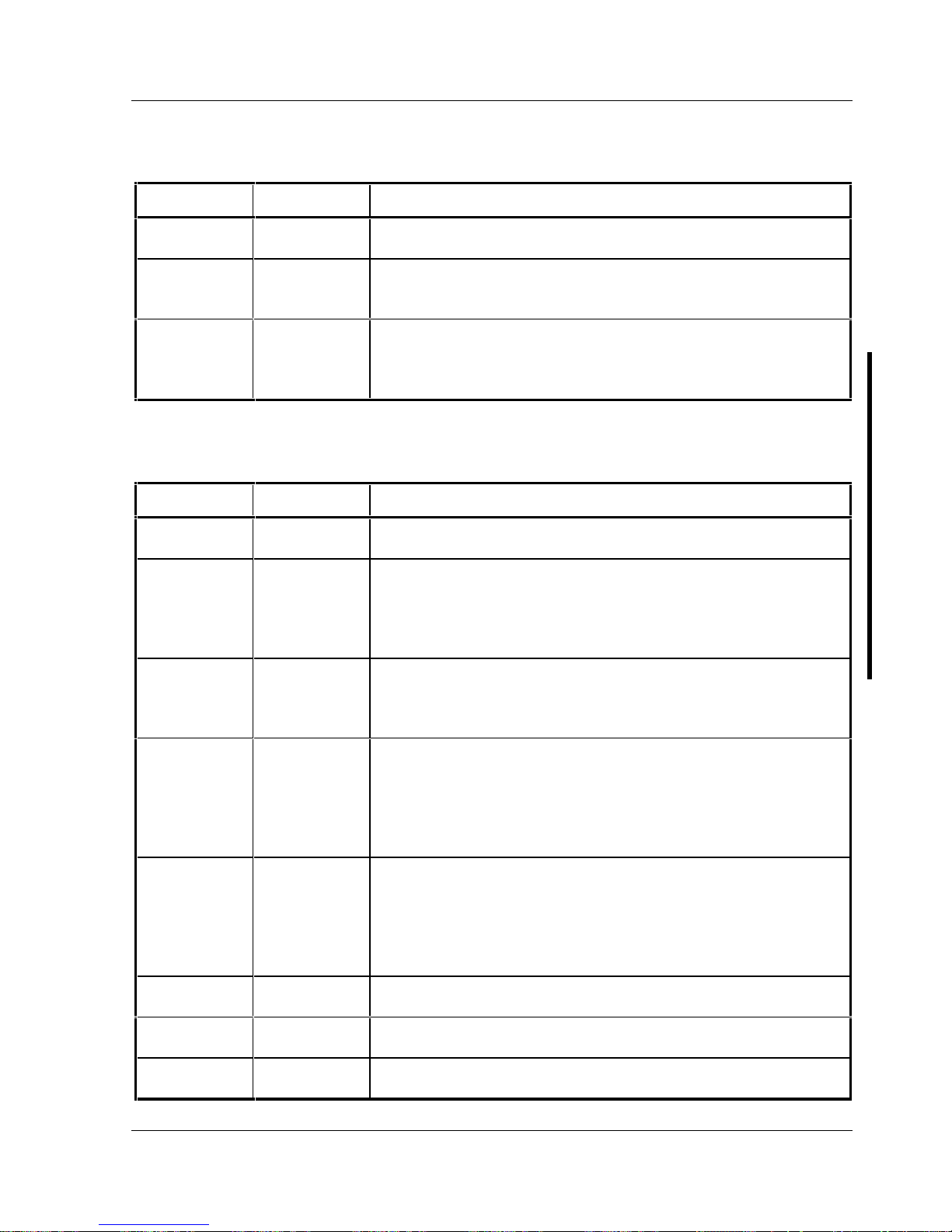
Boot Options (continued)
Menu Fields Settings Comments
Summary
screen
Enabled
Disabled
Enabling this option causes the computer to display configuration
parameters (in the form of a summary screen) during boot.
Fixed Disk Setup Options
IDE Adapter 0/1 Master/Slave
Menu Fields Settings Comments
Autotype fixed
disk
Press [Enter] to detect and fill in the installed hard disk drive
parameters in the remaining fields.
Type
1 to 39
User
Selecting 1 to 39 automatically fills in the remaining fields in this
menu.
Selecting User prompts to fill in the remaining fields with the
installed hard disk drive’s parameters.
Cylinders
0 to 4095 Displays the number of cylinders.
Heads
1 to 64 Displays the number of heads.
Sectors/track
0 to 63 Displays the number of sectors/tracks.
Landing zone
0 to 4095 Displays the number of cylinders specified as the landing zone for
read/write heads.
Write
precomp
0 to 4095
None
Displays the number of cylinders that have their write timing
changed.
Multi-sector
transfers
4 blocks
8 blocks
16 blocks
32 blocks
Auto
Determines the number of sectors per block for multiple sector
transfers.
Auto refers to the size of the disk returns when queried.
LBA control
mode
Disabled
Enabled
Enables or disables the LBA hard disk drive addressing option.
32 bit I/O
Disabled
Enabled
Enables or disables the 32-bit hard disk drive data transfer option.
Transfer
mode
Fast PIO3
Standard
Fast PIO1
Fast PIO2
Selects the method of data transfer to and from the hard disk drive.
Autotype the hard disk drive to select the optimum transfer mode.

Utilities & C onfiguration Digital CELEBRIS Pentium PC
22 M C S Logistics Engineering - N ijm egen
Keyboard Features
Menu Fields Settings Comments
Numlock
Auto
On
Off
Turns Numlock on or off each time the computer boots.
Key click
Disabled
Enabled
Enables or disables the audible key click feature.
Keyboard
auto-repeat
rate
30/sec, 2/sec
6/sec, 10/sec
13.3/sec
21.8/sec
26.7/sec
Sets the number of times a second to repeat a keystroke while holding
the key down.
Keyboard
auto-repeat
delay
1/2 sec, 3/4 sec
1 sec, 1/4 sec
Sets the delay time after a key is held down before it begins to repeat
a keystroke.
Memory and Cache Options
Menu Fields Settings Comments
Internal cache
Enabled
Disabled
Enables or disables the computer′s internal cache.
External
cache
Disabled
Enabled
Enables or disables the computer′s external cache.
System
shadow
Enabled
Disabled
Enables or disables the computer’s BIOS shadowing option.
Video shadow
Enabled
Disabled
Enables or disables the computer's shadow video option.
Shadow at:
C8000h
CC000h
D0000h
D4000h
D8000h
DC000h
Enabled
Disabled
Allows to enable or disable shadowing of individual ROM segments
to increase computer performance.
AT bus space
Disabled
F80000h,
.5MB
F00000h, 1MB
Memory hole not available, upper memory is contiguous.
Sets the memory hole at address F80000 with .5 MB memory
available.
Sets the memory hole at address F00000 with 1 MB memory
available.
Digital CELEBRIS Pentium PC Utilities & Configuration
MCS Logistics Engineering - Nijmegen 23
Advanced Chip Set Control
Menu Fields Settings Comments
Post I/O
writes
Disabled
Enabled
Enabling this option increases the computer’s performance.
PCI slot 1/2
latency timer
Default, 8, 10,
18, 20, ..., F0
F8
Enables to set the PCI latency timer (in PCI clocks) for each PCI
device.
VGA palette
snoop
Enabled
Disabled
Use with VGA and non-VGA compatible PCI add-in cards to inform
card not to claim VGA palette writes.
Use to inform VGA and non-VGA compatible add-in cards to claim
VGA palette writes.
Integrated Peripherals
Menu Fields Settings Comments
Mouse port
Disabled
Enabled
Enables or disables the mouse port.
Parallel port
Auto
Disabled
3BC, IRQ 7
378, IRQ 7
278, IRQ 5
Enables or disables the onboard port at the specified address.
Parallel port
mode
Compatible
mode
Bi-directional
mode
Sets the onboard parallel port mode.
Compatible mode - standard printer connection.
Bi-directional mode - PS/2 compatible mode and able to receive data.
Serial port 1
Auto
Disabled
3F8, IRQ 4
2F8, IRQ 3
3E8, IRQ4
2E8, IRQ3
Enables or disables onboard serial port 1 at the specified address.
Serial port 2
Auto
Disabled
3F8, IRQ 4
2F8, IRQ 3
3E8, IRQ4
2E8, IRQ3
Enables or disables onboard serial port 2 at the specified address.
Diskette
controller
Enabled
Disabled
Enables or disables the onboard diskette controller.
Exchange
diskette drives
Disabled
Enabled
Enables to logically exchange physical diskette drive designations.
Diskette write
protection
Disabled
Enabled
Enables or disables the selected diskette drive’s write protect option.

Utilities & C onfiguration Digital CELEBRIS Pentium PC
24 M C S Logistics Engineering - N ijm egen
IDE adapter
0/1
Enabled
Disabled
Enables or disables the onboard IDE controller.
Digital CELEBRIS Pentium PC Utilities & Configuration
MCS Logistics Engineering - Nijmegen 25
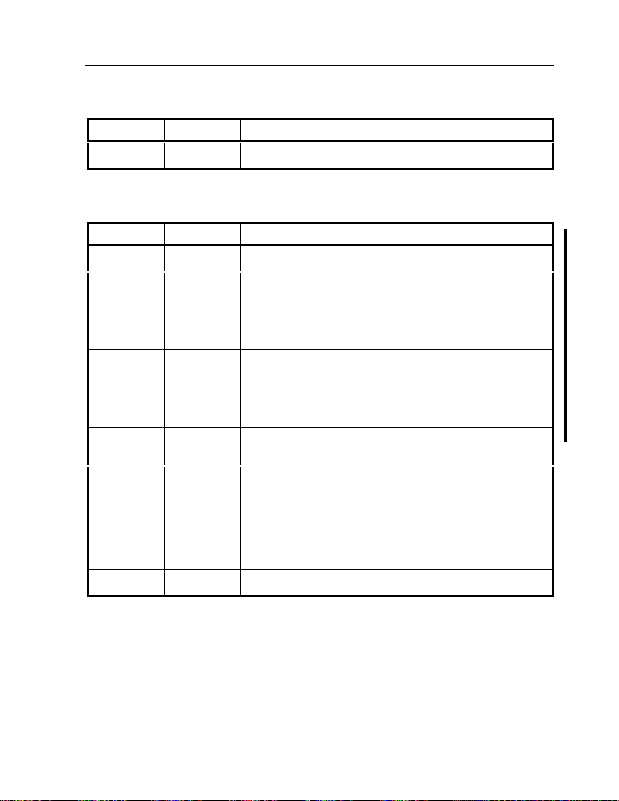
Large Disk Access Mode
Menu Fields Settings Comments
Large disk
access mode
DOS
Other
Select DOS when MS-DOS has been installed. Select Other when
another operating system has been installed.
Power Options
Menu Fields Settings Comments
Power
management
Enabled
Disabled
Enables or disables the computer’s power management options.
Monitor
suspend timer
Disabled
1 min.
5 min.
10 min.
20 min.
30 min.
Allows to disable the monitor suspend feature or, after a set period of
keyboard, mouse, or keyboard controller inactivity, to place the
monitor in a suspend state (minimum power saving state).
Monitor off
timer
Disabled
1 min.
5 min.
10 min.
20 min.
30 min.
Allows to disable the monitor off feature or, after a set period of
keyboard or mouse inactivity, to place the monitor in an off state
(one-half power saving state).
Hard disk
suspend timer
Enabled
Disabled
Allows to disable or enable the hard disk suspend timer feature or
after a set period of disk drive inactivity (approximately 21 minutes),
allows the hard disk drive to spin down its motor to save power.
System
suspend timer
Disabled
30 min.
1 hour
1.5 hours
2 hours
3 hours
6 hours
12 hours
Allows to disable the system suspend feature or, after a set period of
computer inactivity, to place the computer in a suspend state
(maximum power saving state).
Quick suspend
Enabled
Disabled
Enabling this option allows to put the computer in suspend mode by
pressing [Ctrl] + [Alt] + [Esc].

Utilities & C onfiguration Digital CELEBRIS Pentium PC
26 M C S Logistics Engineering - N ijm egen
Security Options
Menu Fields Settings Comments
Supervisor
password is
Not user
selectable
Tells whether or not the supervisor’s password is enabled or disabled.
User password
is
Not user
selectable
Tells whether or not the user’s password is enabled or disabled.
Set supervisor
password
Press [Enter] Enables to set a supervisor password.
Set user
password
Press [Enter] Enables to set a user password.
Password on
boot
Enabled
Disabled
Enables or disables the enter password on boot option.
Diskette access
Supervisor
User
Enables to control who has access to diskette drives.
Fixed disk
boot sector
Normal
Write protect
Enables to write protect the boot sector on the hard disk drive.
System
backup
reminder
Disabled
Daily
Weekly
Monthly
Enables or disables the system backup reminder message.
Virus check
reminder
Disabled
Daily
Weekly
Monthly
Enables or disables the virus check reminder message.

Digital CELEBRIS Pentium PC Service Procedures
MCS Logistics Engineering - Nijmegen 27
Chapter 3 Service Procedures
Safety Requirements
WARNING
Static electricity collects on non-conductors such as paper, cloth, or plastic. A static
discharge can be damaging even though you often cannot see or feel it.
The following safety precautions must be observed to insure product and personal safety and prevent
damage to circuit boards and/or components:
♦ Always wear an ESD wrist strap when handling ESD sensitive material and be sure it is properly
connected.
♦ Keep circuit boards and components away from non-conductors.
♦ Keep clothing away from circuit boards and components.
♦ Keep circuit boards in anti-static bags.
♦ Be cautious when AC power is exposed when working on an assembly.
♦ Always use an isolation transformer when diagnosing terminals, monitors or power supplies when
AC power is applied.
♦ Be cautious of very high voltage potentials when working with monitors.
There should be an approved insulating mat (for technician’s safety) in front of any workbench where
monitors, terminals or power modules are being serviced when power is applied.
NOTE Do NOT wear ESD straps when working on terminals, monitors or power supplies
when AC power is applied. This is to avoid the hazard of electrical shock.

Service Procedures Digital CELEBRIS Pentium PC
28 M C S Logistics Engineering - N ijm egen
Recommended Tools
The following tools are needed for servicing Digital PC systems. Note that test equipment must be
calibrated.
♦ Multimeter (4 1/2 digit)
♦ A philips screwdriver
♦ An antistatic wrist strap
Other Materials Needed
Cleaning agent should be an all purpose cleaner that is used in-house.
Special Tools Required
None.
Remedial Diagnostic Test Software
♦ QAPLUS/fe, PC Advanced Diagnostic Software, latest version.
Supplier information:
Diagsoft, Inc.
5615 Scotts Valley Drive, Suite 140
Scotts Valley, California 95066, U.S.A.
Voice: 1-408-438-8247
Fax: 1-408-438-7113
Internet: http://www.diagsoft.com (Diagsoft, Inc. homepage)
Recommended Virus Detection and Cleanup Software
♦ F-PROT, Virus Detection and Cleanup Software, latest version.
Supplier information:
North America, South America, Australia and New Zealand:
Command Software Systems Inc.
Tel: +1-407-575 3200
Fax: +1-407-575 3026

Digital CELEBRIS Pentium PC Service Procedures
MCS Logistics Engineering - Nijmegen 29
Most of Europe, Africa, Middle and Far East:
Data Fellows Ltd
Paivantaite 8
FIN-02210 ESPOO
FINLAND
tel: +358-0-478 444
fax: +358-0-478 44 599
e-mail: f-prot@datafellows.fi
Internet: http://www.datafellows.fi (Data Fellows Ltd. homepage)
ECO/FCO Information
BIOS Version Information
Refer to the Digital DECpc Bulletin Board Support (telephone number: xx33 92960312) for the latest
information on BIOS upgrades.
 Loading...