

Digital Equipment VAX 4000, BA42B Maintenance Manual

VAX4000
BA42BEnclosureMaintenance
Order Number: EK–472AB–MG. B01
August 1994
This manual provides reference, installation, and maintenance information
for the BA42B Enclosure used with the VAX 4000 Model 100/100A/105A
systems.
Digital Equipment Corporation
Maynard, Massachusetts

August, 1994
Digital Equipment Corporation makes no representations that the use of its products in the
manner described in this publication will not infringe on existing or future patent rights, nor do
the descriptions contained in this publication imply the granting of licenses to make, use, or sell
equipment or software in accordance with the description.
© Digital Equipment Corporation 1994. All Rights Reserved.
The postpaid Reader’s Comments forms at the end of this document request your critical
evaluation to assist in preparing future documentation.
The following are trademarks of Digital Equipment Corporation: DEC, Digital, MicroVAX,
OpenVMS, Q–bus, ThinWire, TK, VAX, VAX DOCUMENT, VT, and the DIGITAL logo.
All other trademarks and registered trademarks are the property of their respective holders.
S2484
This document was prepared using VAX DOCUMENT Version 2.1.

Contents
Preface . . . . . . . . . . . . . . . . . . . . . . . . . . . . . . . . . . . . . . . . . . . . . . . . . . . . . xi
1 Enclosure Description
1.1 Mass Storage Device Areas . . . . . . . . . . . . . . . . . . . . . . . . . . . . . 1–2
1.2 Controls, Indicators, Ports, and Connectors . . . . . . . . . . . . . . . . . 1–3
1.3 Power and Signal Distribution . . . . . . . . . . . . . . . . . . . . . . . . . . . 1–9
1.4 Air Circulation . . . . . . . . . . . . . . . . . . . . . . . . . . . . . . . . . . . . . . . 1–11
1.5 Configuration Guidelines . . . . . . . . . . . . . . . . . . . . . . . . . . . . . . . 1–12
1.5.1 Memory Configurations . . . . . . . . . . . . . . . . . . . . . . . . . . . . . 1–12
1.5.2 Communications Options . . . . . . . . . . . . . . . . . . . . . . . . . . . . 1–15
1.5.3 Mass Storage Devices . . . . . . . . . . . . . . . . . . . . . . . . . . . . . . . 1–17
2 Installation Procedures
2.1 Preparing the Site . . . . . . . . . . . . . . . . . . . . . . . . . . . . . . . . . . . . 2–1
2.1.1 Enclosure Dimensions . . . . . . . . . . . . . . . . . . . . . . . . . . . . . . 2–1
2.1.2 Additional Equipment . . . . . . . . . . . . . . . . . . . . . . . . . . . . . . 2–2
2.1.3 Operating Environment . . . . . . . . . . . . . . . . . . . . . . . . . . . . . 2–3
2.1.4 Electrostatic Discharge . . . . . . . . . . . . . . . . . . . . . . . . . . . . . 2–3
2.1.5 Heat Dissipation . . . . . . . . . . . . . . . . . . . . . . . . . . . . . . . . . . 2–3
2.1.6 Temperature, Humidity, and Altitude Ranges . . . . . . . . . . . . 2–4
2.1.7 Electrical Requirements . . . . . . . . . . . . . . . . . . . . . . . . . . . . . 2–4
2.2 Unpacking the System . . . . . . . . . . . . . . . . . . . . . . . . . . . . . . . . . 2–5
2.3 Installing the BA42B System . . . . . . . . . . . . . . . . . . . . . . . . . . . . 2–7
2.3.1 Installing a BA42B-Based VAX 4000 Model 100 . . . . . . . . . . 2–7
2.3.1.1 Identifying the Ports and Connectors on the System . . . . 2–7
2.3.1.2 Connecting the Console Terminal . . . . . . . . . . . . . . . . . . . 2–7
2.3.1.3 Connecting the ThinWire Terminator or Loopback
Connector . . . . . . . . . . . . . . . . . . . . . . . . . . . . . . . . . . . . . 2–10
2.3.1.4 Connecting the SCSI Terminator . . . . . . . . . . . . . . . . . . . 2–13
2.3.1.5 Connecting the DSSI Terminator . . . . . . . . . . . . . . . . . . . 2–14
2.3.1.6 Connecting the System Unit Power Cord . . . . . . . . . . . . . 2–15
iii

2.3.1.7 Turning On the System . . . . . . . . . . . . . . . . . . . . . . . . . . 2–16
2.3.2 Installing a BA42B-Based VAX 4000 Model 100A/105A . . . . . 2–17
2.3.2.1 Identifying the Ports and Connectors on the System . . . . 2–17
2.3.2.2 Connecting the Console Terminal . . . . . . . . . . . . . . . . . . . 2–17
2.3.2.3 Connecting the ThinWire Terminator or Loopback
Connector . . . . . . . . . . . . . . . . . . . . . . . . . . . . . . . . . . . . . 2–20
2.3.2.4 Connecting the SCSI Terminator . . . . . . . . . . . . . . . . . . . 2–23
2.3.2.5 Connecting the DSSI Terminator . . . . . . . . . . . . . . . . . . . 2–24
2.3.2.6 Connecting the System Unit Power Cord . . . . . . . . . . . . . 2–25
2.3.2.7 Turning On the System . . . . . . . . . . . . . . . . . . . . . . . . . . 2–26
3 Removing and Replacing Field Replaceable Units
3.1 Removing the Enclosure Cover . . . . . . . . . . . . . . . . . . . . . . . . . . 3–5
3.2 Removing an MS44 or MS44L Memory Module . . . . . . . . . . . . . . 3–6
3.3 Removing the Upper Drive-Mounting Shelf . . . . . . . . . . . . . . . . . 3–9
3.4 Removing the RX26 Diskette Drive Assembly . . . . . . . . . . . . . . . 3–13
3.4.1 Removing the RX26 FDI/SCSI Board . . . . . . . . . . . . . . . . . . . 3–14
3.4.2 Separating the RX26 Diskette Drive from the Mounting
Bracket . . . . . . . . . . . . . . . . . . . . . . . . . . . . . . . . . . . . . . . . . 3–15
3.4.3 Setting the SCSI ID on the Replacement RX26 FDI/SCSI
Board . . . . . . . . . . . . . . . . . . . . . . . . . . . . . . . . . . . . . . . . . . . 3–16
3.5 Removing a TZ30 Tape Drive . . . . . . . . . . . . . . . . . . . . . . . . . . . . 3–19
3.5.1 Separating the TZ30 Tape Drive from the Mounting
Bracket . . . . . . . . . . . . . . . . . . . . . . . . . . . . . . . . . . . . . . . . . 3–21
3.5.2 Setting the SCSI ID on the Replacement TZ30 Tape
Drive . . . . . . . . . . . . . . . . . . . . . . . . . . . . . . . . . . . . . . . . . . . 3–22
3.6 Removing a TZK10/TZK11 Tape Drive . . . . . . . . . . . . . . . . . . . . . 3–23
3.6.1 Separating the TZK10/TZK11 Tape Drive from the Mounting
Bracket . . . . . . . . . . . . . . . . . . . . . . . . . . . . . . . . . . . . . . . . . 3–25
3.6.2 Setting the SCSI ID of the Replacement TZK10/TZK11 Tape
Drive . . . . . . . . . . . . . . . . . . . . . . . . . . . . . . . . . . . . . . . . . . . 3–26
3.7 Removing a TLZ06/TLZ07 Tape Drive . . . . . . . . . . . . . . . . . . . . . 3–28
3.7.1 Separating the TLZ06/TLZ07 Tape Drive from the Mounting
Bracket . . . . . . . . . . . . . . . . . . . . . . . . . . . . . . . . . . . . . . . . . 3–30
3.7.2 Setting the SCSI ID and Option Switches of the Replacement
TLZ06/TLZ07 Tape Drive . . . . . . . . . . . . . . . . . . . . . . . . . . . . 3–31
3.8 Removing an RF31T/RF35/RF36 Disk Drive . . . . . . . . . . . . . . . . 3–32
3.8.1 Separating the RF-series Drive from the Mounting
Bracket . . . . . . . . . . . . . . . . . . . . . . . . . . . . . . . . . . . . . . . . . 3–33
3.8.2 Setting the DSSI ID . . . . . . . . . . . . . . . . . . . . . . . . . . . . . . . . 3–35
3.9 Removing an RRD42 CD–ROM Drive . . . . . . . . . . . . . . . . . . . . . 3–37
iv

3.9.1 Separating the RRD42 CD–ROM Drive from the Mounting
Bracket . . . . . . . . . . . . . . . . . . . . . . . . . . . . . . . . . . . . . . . . . 3–39
3.9.2 Setting the SCSI ID on the Replacement RRD42 CD–ROM
Drive . . . . . . . . . . . . . . . . . . . . . . . . . . . . . . . . . . . . . . . . . . . 3–41
3.10 Removing an RRD43 CD–ROM Drive . . . . . . . . . . . . . . . . . . . . . 3–43
3.10.1 Separating the RRD43 CD–ROM Drive from the Mounting
Bracket . . . . . . . . . . . . . . . . . . . . . . . . . . . . . . . . . . . . . . . . . 3–45
3.10.2 Setting the SCSI ID on the Replacement RRD43 CD–ROM
Drive . . . . . . . . . . . . . . . . . . . . . . . . . . . . . . . . . . . . . . . . . . . 3–47
3.11 Removing the Upper and Lower Drive-Mounting Shelf
Combination . . . . . . . . . . . . . . . . . . . . . . . . . . . . . . . . . . . . . . . . . 3–48
3.12 Removing the SCSI Cable from the Enclosure . . . . . . . . . . . . . . . 3–52
3.13 Removing the DSSI Cable from the Enclosure . . . . . . . . . . . . . . . 3–53
3.14 Removing the DSSI Daughter Board . . . . . . . . . . . . . . . . . . . . . . 3–55
3.14.1 Changing the DSSI ID . . . . . . . . . . . . . . . . . . . . . . . . . . . . . . 3–58
3.15 Removing the DSW42 Synchronous Communications Option . . . 3–60
3.15.1 Removing the DSW42 Logic Board . . . . . . . . . . . . . . . . . . . . 3–60
3.15.2 Removing the DSW42 Input/Output Cable . . . . . . . . . . . . . . 3–61
3.15.3 Removing the DSW42 Input/Output Module . . . . . . . . . . . . . 3–62
3.16 Removing the DHW42 Asynchronous Communications
Option . . . . . . . . . . . . . . . . . . . . . . . . . . . . . . . . . . . . . . . . . . . . . 3–64
3.16.1 Removing the DHW42 Logic Board . . . . . . . . . . . . . . . . . . . . 3–64
3.16.2 Removing the DHW42 Input/Output Cable . . . . . . . . . . . . . . 3–65
3.16.3 Removing the DHW42 Input/Output Module . . . . . . . . . . . . . 3–66
3.17 Removing the CPU Module . . . . . . . . . . . . . . . . . . . . . . . . . . . . . 3–68
3.18 Replacing the CPU Module . . . . . . . . . . . . . . . . . . . . . . . . . . . . . 3–72
3.19 Removing the Power Supply . . . . . . . . . . . . . . . . . . . . . . . . . . . . 3–73
A Pin Specifications for the Ports on the BA42B System
B Related Documentation
C Recommended Spare Parts List
v

Glossary
Index
Figures
1–1 BA42B Enclosure . . . . . . . . . . . . . . . . . . . . . . . . . . . . . . . . . . 1–2
1–2 Common VAX 4000 BA42B-Based Systems Controls,
Indicators, Ports, and Connectors for all Models . . . . . . . . . . 1–4
1–3 Ports and Connectors Unique to the VAX 4000 Model 100 . . . 1–5
1–4 Ports and Connectors Unique to the VAX 4000 Model
100A/105A . . . . . . . . . . . . . . . . . . . . . . . . . . . . . . . . . . . . . . . 1–6
1–5 Power Distribution . . . . . . . . . . . . . . . . . . . . . . . . . . . . . . . . . 1–10
1–6 Signal Distribution . . . . . . . . . . . . . . . . . . . . . . . . . . . . . . . . . 1–11
1–7 Memory Expansion Connectors on the KA52/KA53 CPU
Module . . . . . . . . . . . . . . . . . . . . . . . . . . . . . . . . . . . . . . . . . . 1–13
1–8 Identifying Appropriate Banks of SIMM Connectors . . . . . . . 1–14
1–9 Communications Options in Model 100/100A/105A
Systems . . . . . . . . . . . . . . . . . . . . . . . . . . . . . . . . . . . . . . . . . 1–16
1–10 Mass Storage Device Combinations in the BA42B
Enclosure . . . . . . . . . . . . . . . . . . . . . . . . . . . . . . . . . . . . . . . . 1–18
2–1 BA42B Dimensions . . . . . . . . . . . . . . . . . . . . . . . . . . . . . . . . 2–2
2–2 System Unit and Accessory Tray Contents . . . . . . . . . . . . . . . 2–6
2–3 Connecting the Console Terminal . . . . . . . . . . . . . . . . . . . . . . 2–9
2–4 Connecting the ThinWire Terminator to the System . . . . . . . 2–11
2–5 Connecting the Standard Ethernet Loopback Connector to
the System . . . . . . . . . . . . . . . . . . . . . . . . . . . . . . . . . . . . . . . 2–12
2–6 Connecting the SCSI Terminator . . . . . . . . . . . . . . . . . . . . . . 2–13
2–7 Connecting the DSSI Terminator . . . . . . . . . . . . . . . . . . . . . . 2–14
2–8 Connecting the Power Cord . . . . . . . . . . . . . . . . . . . . . . . . . . 2–15
2–9 Turning On the System . . . . . . . . . . . . . . . . . . . . . . . . . . . . . 2–16
2–10 Connecting the Console Terminal. . . . . . . . . . . . . . . . . . . . . . 2–19
2–11 Connecting the ThinWire Terminator to the System . . . . . . . 2–21
2–12 Connecting the Standard Ethernet Loopback Connector to
the VAX 4000 Models 100A/105A . . . . . . . . . . . . . . . . . . . . . . 2–22
2–13 Connecting the SCSI Terminator . . . . . . . . . . . . . . . . . . . . . . 2–23
2–14 Connecting the DSSI Terminator . . . . . . . . . . . . . . . . . . . . . . 2–24
2–15 Connecting the Power Cord . . . . . . . . . . . . . . . . . . . . . . . . . . 2–25
vi

2–16 Turning On the System . . . . . . . . . . . . . . . . . . . . . . . . . . . . . 2–26
3–1 Major FRUs in the BA42B Enclosure . . . . . . . . . . . . . . . . . . . 3–4
3–2 Removing the Enclosure Cover . . . . . . . . . . . . . . . . . . . . . . . 3–5
3–3 Memory Module Connectors on the KA52/53 CPU Module . . 3–7
3–4 Removing a Memory Module . . . . . . . . . . . . . . . . . . . . . . . . . 3–8
3–5 Removing the Upper Drive-Mounting Shelf . . . . . . . . . . . . . . 3–10
3–6 Disconnecting the DSSI Cables from the Drives . . . . . . . . . . 3–11
3–7 Removing the Upper Drive-Mounting Shelf . . . . . . . . . . . . . . 3–12
3–8 Removing the RX26 Diskette Drive Assembly . . . . . . . . . . . . 3–14
3–9 Removing the RX26 FDI/SCSI Board . . . . . . . . . . . . . . . . . . . 3–15
3–10 Separating the Mounting Bracket from the RX26 Diskette
Drive . . . . . . . . . . . . . . . . . . . . . . . . . . . . . . . . . . . . . . . . . . . 3–16
3–11 Location of the SCSI ID Switches on the RX26 FDI/SCSI
Board . . . . . . . . . . . . . . . . . . . . . . . . . . . . . . . . . . . . . . . . . . . 3–17
3–12 How to Reach the SCSI ID Switches on the RX26 FDI/SCSI
Board . . . . . . . . . . . . . . . . . . . . . . . . . . . . . . . . . . . . . . . . . . . 3–18
3–13 Removing a TZ30 Tape Drive . . . . . . . . . . . . . . . . . . . . . . . . . 3–20
3–14 Separating the Mounting Bracket from the TZ30 Tape
Drive . . . . . . . . . . . . . . . . . . . . . . . . . . . . . . . . . . . . . . . . . . . 3–21
3–15 TZ30 SCSI ID Switch Locations . . . . . . . . . . . . . . . . . . . . . . . 3–22
3–16 Removing the TZK10/TZK11 Tape Drive . . . . . . . . . . . . . . . . 3–24
3–17 Separating the Mounting Bracket from the TZK10/TZK11
Tape Drive . . . . . . . . . . . . . . . . . . . . . . . . . . . . . . . . . . . . . . . 3–25
3–18 Locations of the SCSI ID Jumper Wires on the TZK10/TZK11
Tape Drive . . . . . . . . . . . . . . . . . . . . . . . . . . . . . . . . . . . . . . . 3–27
3–19 Removing the TLZ06/TLZ07 Tape Drive . . . . . . . . . . . . . . . . 3–29
3–20 Separating the Mounting Bracket from the TLZ06/TLZ07
Tape Drive . . . . . . . . . . . . . . . . . . . . . . . . . . . . . . . . . . . . . . . 3–30
3–21 Locations of the SCSI ID and Option Switches on the
TLZ06/TLZ07 Tape Drive . . . . . . . . . . . . . . . . . . . . . . . . . . . . 3–31
3–22 Removing a Sample RF31T/RF35/RF36 Disk Drive Option
. . . . . . . . . . . . . . . . . . . . . . . . . . . . . . . . . . . . . . . . . . . . . . . . 3–33
3–23 Separating the Mounting Bracket from the RF-Series
Drive . . . . . . . . . . . . . . . . . . . . . . . . . . . . . . . . . . . . . . . . . . . 3–34
3–24 Sample RF31T/RF35/RF36 Disk Drive Option with Mounting
Brackets . . . . . . . . . . . . . . . . . . . . . . . . . . . . . . . . . . . . . . . . . 3–35
3–25 Removing the RRD42 CD–ROM Drive . . . . . . . . . . . . . . . . . . 3–38
3–26 Separating the Mounting Bracket from the RRD42 CD–ROM
Drive . . . . . . . . . . . . . . . . . . . . . . . . . . . . . . . . . . . . . . . . . . . 3–40
vii

3–27 RRD42 SCSI ID Jumper Wire Locations . . . . . . . . . . . . . . . . 3–42
3–28 Removing the RRD43 CD–ROM Drive . . . . . . . . . . . . . . . . . . 3–44
3–29 Separating the Mounting Bracket from the RRD43 CD–ROM
Drive . . . . . . . . . . . . . . . . . . . . . . . . . . . . . . . . . . . . . . . . . . . 3–46
3–30 Removing the Upper and Lower Drive-Mounting Shelf
Combination . . . . . . . . . . . . . . . . . . . . . . . . . . . . . . . . . . . . . . 3–49
3–31 Disconnecting the SCSI Cable . . . . . . . . . . . . . . . . . . . . . . . . 3–50
3–32 Disconnecting the DSSI Cable . . . . . . . . . . . . . . . . . . . . . . . . 3–51
3–33 Separating the Upper Drive-Mounting Shelf from the Lower
Drive-Mounting Shelf . . . . . . . . . . . . . . . . . . . . . . . . . . . . . . . 3–53
3–34 Removing the DSSI Cable from the Daughter Board . . . . . . . 3–54
3–35 Removing the DSSI Daughter Board . . . . . . . . . . . . . . . . . . . 3–56
3–36 Removing the DSSI Cable and Daughter Board . . . . . . . . . . . 3–57
3–37 DSSI ID Jumper Locations . . . . . . . . . . . . . . . . . . . . . . . . . . 3–59
3–38 Removing the DSW42 Logic Board . . . . . . . . . . . . . . . . . . . . 3–61
3–39 Removing the DSW42 Input/Output Cable . . . . . . . . . . . . . . 3–62
3–40 Removing the DSW42 Input/Output Module . . . . . . . . . . . . . 3–63
3–41 Removing the DHW42 Logic Board . . . . . . . . . . . . . . . . . . . . 3–65
3–42 Removing the DHW42 Input/Output Cable . . . . . . . . . . . . . . 3–66
3–43 Removing the DHW42 Input/Output Module . . . . . . . . . . . . . 3–67
3–44 Disconnecting the Cables from the CPU Module . . . . . . . . . . 3–69
3–45 Removing the CPU Module . . . . . . . . . . . . . . . . . . . . . . . . . . 3–71
3–46 Removing the Power Supply . . . . . . . . . . . . . . . . . . . . . . . . . 3–74
A–1 Pin Specifications for the Ports on the BA42B System . . . . . . A–2
Tables
1–1 Functions of the Controls, Indicators, Ports, and
Connectors . . . . . . . . . . . . . . . . . . . . . . . . . . . . . . . . . . . . . . . 1–7
1–2 Power Supply dc Outputs . . . . . . . . . . . . . . . . . . . . . . . . . . . . 1–9
1–3 BA42B Communications Options . . . . . . . . . . . . . . . . . . . . . . 1–15
1–4 DSW42-AA Communications Interface Support . . . . . . . . . . . 1–15
1–5 BA42B Mass Storage Devices . . . . . . . . . . . . . . . . . . . . . . . . . 1–17
2–1 Temperature, Humidity, and Altitude Ranges . . . . . . . . . . . . 2–4
2–2 BA42B Electrical Requirements . . . . . . . . . . . . . . . . . . . . . . . 2–5
2–3 Terminal Settings . . . . . . . . . . . . . . . . . . . . . . . . . . . . . . . . . . 2–8
2–4 Terminal Settings . . . . . . . . . . . . . . . . . . . . . . . . . . . . . . . . . . 2–17
3–1 Major FRUs in the BA42B Enclosure . . . . . . . . . . . . . . . . . . . 3–3
viii

3–2 RF31T/RF35/RF36 DSSI ID Jumper Wire Combinations . . . . 3–36
A–1 Asynchronous Port A and Port B Pin Specifications for the
Eight-Data and 16-Data Line Options . . . . . . . . . . . . . . . . . . A–3
A–2 Asynchronous Port A and Port B Pin Specifications for the
Eight-Modem Control Line Option . . . . . . . . . . . . . . . . . . . . . A–4
A–3 Pin Specifications for Synchronous Port 0 and Port 1 . . . . . . A–6
A–4 Pin Specifications for the External SCSI Connector . . . . . . . . A–9
C–1 Recommended Spare Parts . . . . . . . . . . . . . . . . . . . . . . . . . . . C–1
ix


This manual provides the information that you will need to maintain the
BA42B Enclosure when used with the VAX 4000 Model 100/100A/105A
systems. It contains information about the enclosure, installation information,
and procedures for servicing field replaceable units (FRUs).
Audience
This manual is for Digital™ Services personnel who provide support and
maintenance for systems that use this enclosure. It is also for customers
who have a self-maintenance agreement with Digital Equipment Corporation.
Users of this manual must have experience in replacing hardware components.
Structure of This Manual
This manual is divided into three chapters, three appendixes, a glossary, and
an index:
• Chapter 1 provides an overview of the system enclosure and describes
the controls, mass storage areas and capacity, signal distribution, power
distribution, input and output connections, and configuration guidelines.
• Chapter 2 provides site preparation information and describes how to
install the systems that use the enclosure.
Preface
• Chapter 3 provides instructions on removing and replacing FRUs.
xi

• Appendix A gives the pin specifications for the ports on the back of the
system unit.
• Appendix B gives a list of the related documents.
• Appendix C gives a list of recommended spare parts.
xii

Conventions
The following conventions are used in this manual:
Convention Description
Ctrl/x Ctrl/x indicates that you hold down the Ctrl key while you press
x A lowercase italic x indicates the generic use of a letter. For
italic type Italic type emphasizes important information, indicates variables,
nn nnn.nnn nn A space character separates groups of 3 digits in numerals with 5 or
n.nn A period in numerals signals the decimal point indicator. For
Note A note contains information of special importance to the reader.
Caution A caution contains information to prevent damage to the equipment.
another key or mouse button (indicated here by x).
example, xxx indicates any combination of three alphabetic
characters.
and indicates the complete titles of manuals.
more digits. For example, 10 000 equals ten thousand.
example, 1.75 equals one and three-fourths.
xiii


Enclosure Description
This chapter describes the BA42B Enclosure. It gives information on the
following:
• Mass storage device areas
• Controls, indicators, ports, and connectors
• Power and signal distribution
• Air circulation
• Configuration guidelines
The BA42B Enclosure houses the system unit of the VAX 4000 Model
100/100A/105A systems. It is a desktop-style enclosure (see Figure 1–1).
Note
The VAX 4000 Models 100A/105A can be distinguished from the
Model 100 by the protruding connector panel (see Section 1.2). The
illustrations in this manual will show different models as examples.
Where the functionality differs, it is called to the reader’s attention and
addressed in the text.
1
Enclosure Description 1–1

Enclosure Description
Figure 1–1 BA42B Enclosure
1.1 Mass Storage Device Areas
The BA42B Enclosure contains 3.5-inch (13.5 cm) and 5.25-inch (20.25cm)
half-height mass storage devices. These mass storage devices are mounted
on two drive-mounting shelves. The upper drive-mounting shelf can contain
one, two, or three DSSI drives. The lower drive-mounting shelf can contain
one or two SCSI devices, that is, CD–ROM drives or removable media devices.
See Section 1.5.3 for information about mass storage device combinations and
orientation.
RE_EN06213A_91
1–2 Enclosure Description

Enclosure Description
1.2 Controls, Indicators, Ports, and Connectors
1.2 Controls, Indicators, Ports, and Connectors
The power OK indicator (POK) is on the front of the BA42B Enclosure.
Figure 1–2 shows the common ports and connectors in VAX 4000 BA42B-based
systems. Figure 1–3 and Figure 1–4 show differences between the VAX 4000
Model 100, and the VAX 4000 Models 100A and 105A, respectively. Table 1–1
describes the functions of the controls, indicators, ports, and connectors in all
VAX 4000 BA42B-based systems.
Enclosure Description 1–3
Enclosure Description
1.2 Controls, Indicators, Ports, and Connectors
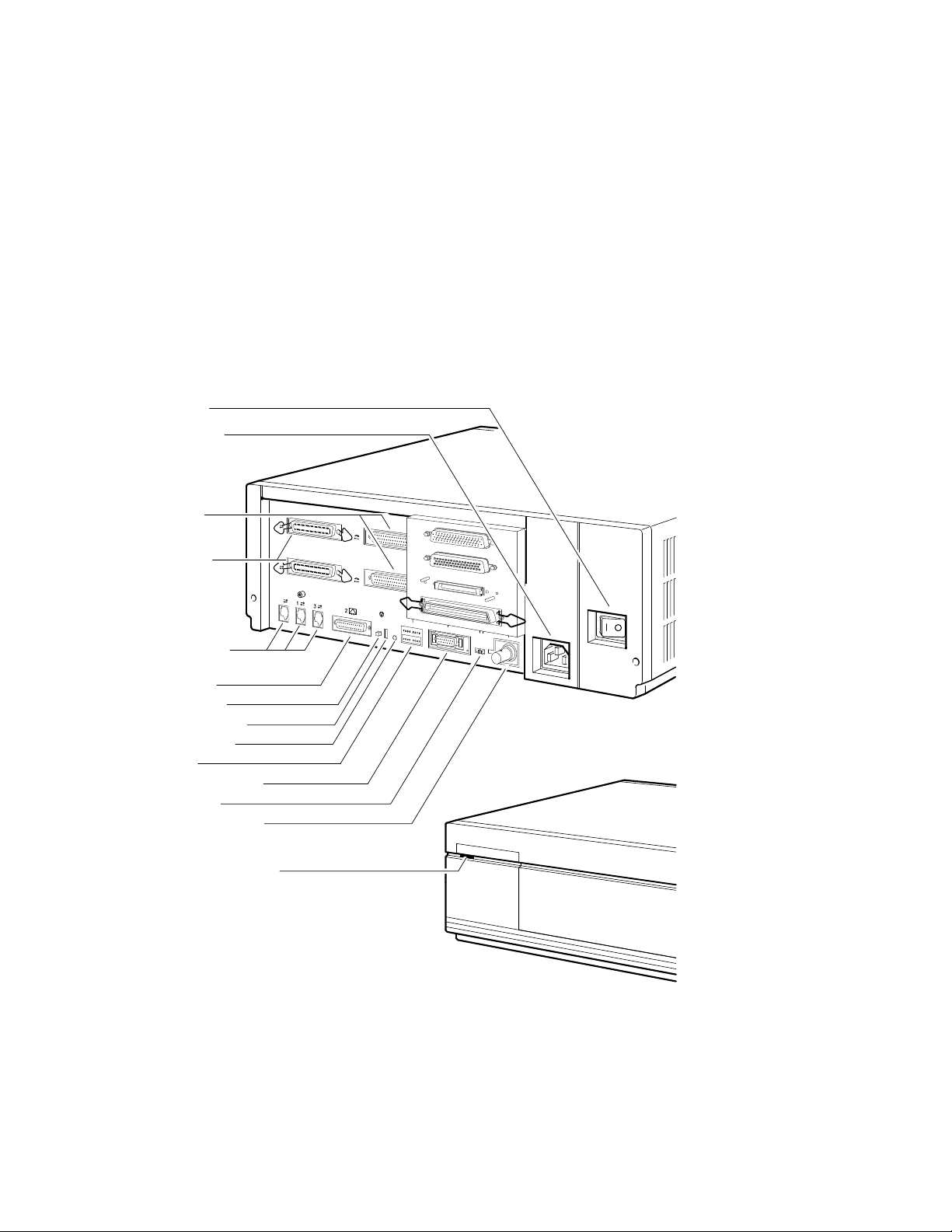
Figure 1–2 Common VAX 4000 BA42B-Based Systems Controls, Indicators,
Ports, and Connectors for all Models
On/Off Switch
ac Power Socket
Synchronous
Communications
Ports (0,1)
Asynchronous
Communications
Ports (A,B)
MMJ Ports (0,1,3)
Asynchronous Modem
Control Port (2)
Halt Push Button
Break/Enable Switch
Break/Enable LED
LED Display
Standard Ethernet Port
Ethernet Switch
ThinWire Ethernet Port
Power OK Indicator (POK)
B
A
0
1
0
1–4 Enclosure Description
MLO-012383
Enclosure Description
1.2 Controls, Indicators, Ports, and Connectors
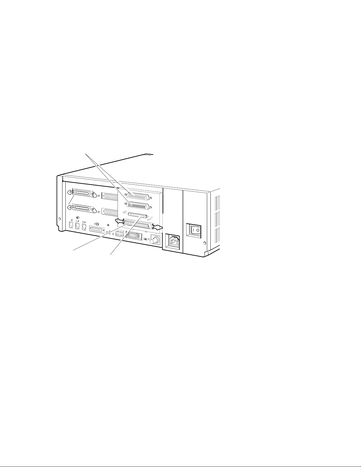
Figure 1–3 Ports and Connectors Unique to the VAX 4000 Model 100
Q-Bus Ports
B
A
0
SCSI Port
1
0
DSSI Port
MLO-012385
Enclosure Description 1–5
Enclosure Description
1.2 Controls, Indicators, Ports, and Connectors
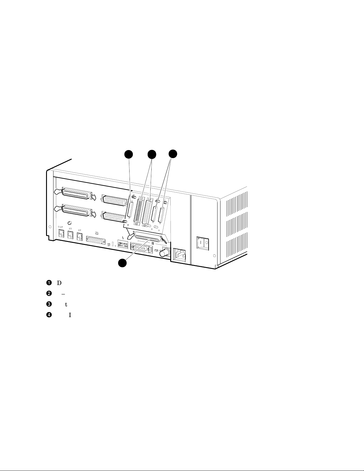
Figure 1–4 Ports and Connectors Unique to the VAX 4000 Model 100A/105A
1
3
DSSI port
Q–bus ports
Optional DSSI ports
SCSI port
1
2
2
2
3
4
MLO-012384
1–6 Enclosure Description

Enclosure Description
1.2 Controls, Indicators, Ports, and Connectors
Table 1–1 Functions of the Controls, Indicators, Ports, and Connectors
Component Description
On/Off switch Applies and stops the power to the system unit as follows:
• On (|)—Applies the ac power to the system unit
• Off (O)—Stops the ac power to the system unit
System ac power socket A socket for the ac power input.
SCSI1port A port that allows you to connect external SCSI devices.
Synchronous communi-
cations ports (0,1)
Asynchronous communi-
cations ports (A,B)
2
2
Two ports that allow you to connect devices that have
synchronous communications support.
One or two ports that provide one of the following
asynchronous communications expansion options:
• Eight DEC423 compatible asynchronous ports
• Sixteen DEC423 compatible asynchronous ports
• Eight EIA-232 compatible modem ports
MMJ3port 0 DEC423 compatible asynchronous port. This port is the
primary console port.
MMJ port 1 DEC423 compatible asynchronous port.
MMJ port 3 DEC423 compatible asynchronous port. This port functions
as an alternate console port when the break/enable switch
is set in the up position when you turn on the system unit.
Asynchronous modem
EIA-232 compatible asynchronous port with modem control.
control port (2)
DSSI Connector
4
Ports for the management of integrated storage products.
Q–bus Connectors Q–bus expansion port which connects the expansion
enclosure.
Halt push button A momentary-contact push button that puts the system in
console mode.
1
Small computer system interface (SCSI).
2
Optional ports that depend on the system configuration.
3
Modified modular jack (MMJ).
4
Digital Storage Systems Interconnect (DSSI); up to three in some optional configurations.
(continued on next page)
Enclosure Description 1–7

Enclosure Description
1.2 Controls, Indicators, Ports, and Connectors
Table 1–1 (Cont.) Functions of the Controls, Indicators, Ports, and Connectors
Component Description
Break/enable switch
5
A two-position switch that determines the function of MMJ
port 3 as follows:
• Up position—MMJ port 3 functions as a console port.
In this state, you can press the Break key on the
keyboard of a terminal connected to MMJ port 3 to put
the system in console mode.
• Down position—MMJ port 3 functions as a normal
communications port. MMJ port 0 functions as a
console port.
Break/enable LED
6
A LED indicator that shows the function of MMJ port 3 as
follows:
• On—MMJ port 3 functions as a console port.
• Off—MMJ port 3 functions as a normal communications
port.
LED display A set of eight LEDs that provide power-up and self-
test diagnostic code information. This is useful for fault
diagnosis when the console terminal is not functioning.
Standard Ethernet port A port that allows you to connect the system to a standard
Ethernet network.
Ethernet switch A two-position switch that determines the type of Ethernet
that the system uses as follows:
• Left position—selects the standard Ethernet type
• Right position—selects the ThinWire™ Ethernet type
ThinWire Ethernet port A port that allows you to connect the system to a ThinWire
Ethernet network.
5
The system recognizes the position of this switch only when you turn on the power.
6
Light emitting diode (LED).
1–8 Enclosure Description

1.3 Power and Signal Distribution
The power supply (30-35042-01) provides power to all the units in the
enclosure. It accepts alternating current (ac) input voltage in the ranges 110 V
ac to 120 V ac (88 V rms1to 132 V rms) and 220 V ac to 240 V ac (176 V rms
to 264 V rms).
The regulators in the power supply maintain the correct direct current (dc)
output voltages, which are independent of the fluctuations in the ac input
power. The power supply can provide a continuous power output of 166
watts (W). The power supply has two internal fans that cool the unit while it
operates. Table 1–2 gives the current specifications of the dc circuits.
Table 1–2 Power Supply dc Outputs
Voltage (dc) Output Current Range in Amperes (dc)
Minimum Maximum
+5.1 3.8 15.0
+12.1 0.18 7.1
-12.0 0.3 1.0
-9.0 0.0 0.2
+3.3 0.0 3.5
Enclosure Description
1.3 Power and Signal Distribution
The power supply (30-35042-01) has the following output connectors:
• A flying lead connector that provides the dc power to the central processing
unit (CPU) module
• One connector on the side of the power supply that provides the dc power
to the devices on the upper drive-mounting shelf
• One connector on the side of the power supply that provides the dc power
to the devices on the lower drive-mounting shelf
Figure 1–5 shows the distribution of power in the BA42B Enclosure.
1
Root mean square.
Enclosure Description 1–9
Enclosure Description
1.3 Power and Signal Distribution
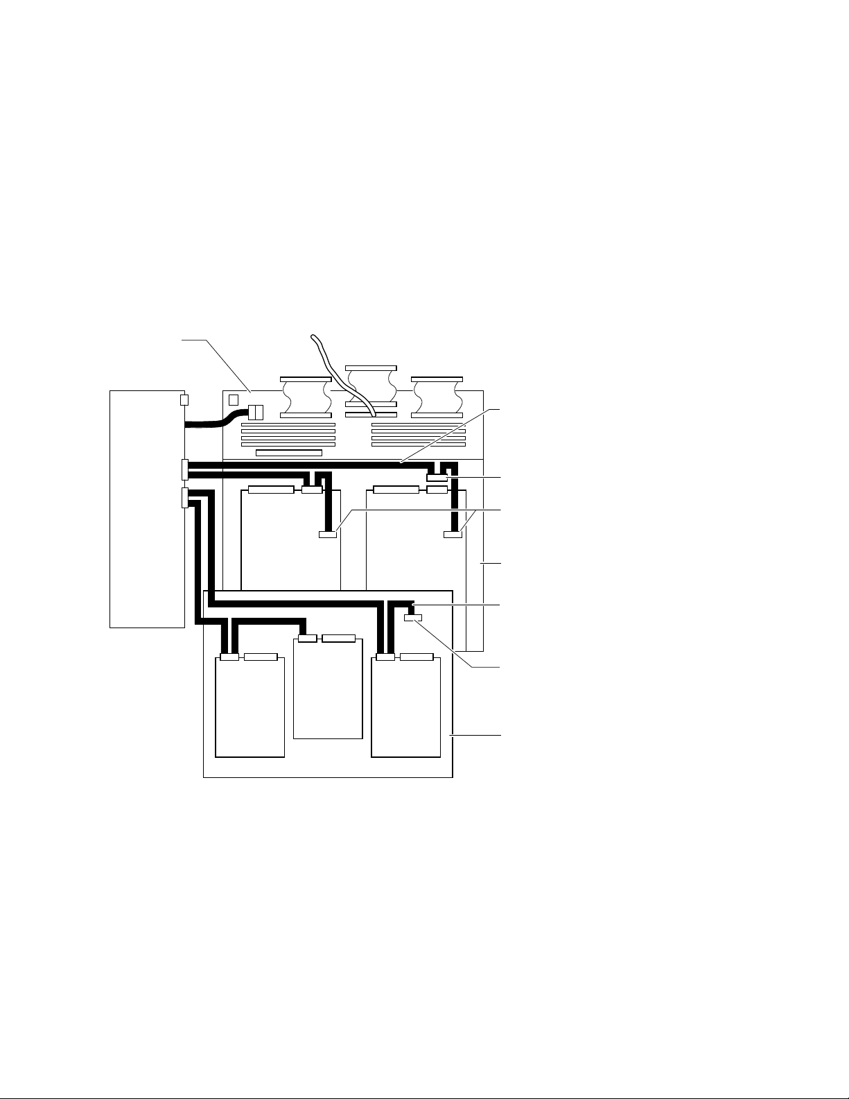
Figure 1–5 Power Distribution
CPU Module
Power
Supply
Lower Shelf
dc Harness
Cable
(17-03018-01)
TZ30 Only
TZK10/11
or
RRD42/42
or
RX26
or
TZ30
RF*
RF*
Note: RF denotes RF31T/RF35/RF36 Disk Drives
RF*
TZK10/11
or
TZ30
or
RX26
or
RRD42/43
RF*
Additional
Connector
for RX26
Lower Drive
Mounting Shelf
Upper Shelf
dc Harness
Cable
(17-03615-01)
Not Used
Upper Drive
Mounting Shelf
MLO-012379
Appendix A provides information on the pin specifications for the connectors.
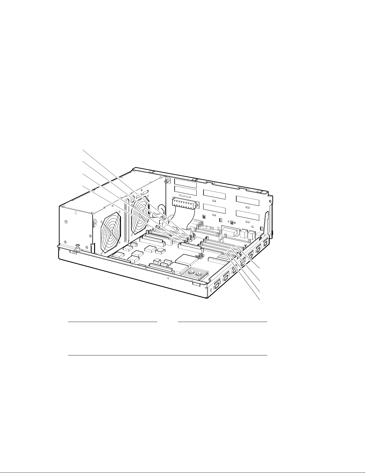
The CPU module is the main source for signal distribution in a BA42B
Enclosure system. The SCSI and DSSI cables are connected to the CPU
module. Each of the other connectors on the cables has a pull-tab. Use the
pull-tab to disconnect the cable from a device. Each pull-tab has a number that
identifies the drive to which the SCSI or DSSI cable connector is connected
(see Figure 1–6).
1–10 Enclosure Description
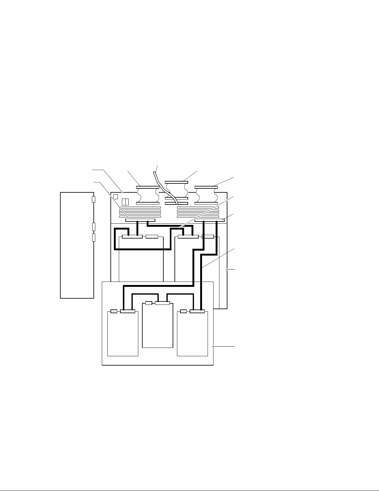
Figure 1–6 Signal Distribution
External
SCSI
CPU Module
Internal SCSI
(17-02944-01)
External
Q-bus
(17-03545-01)
Enclosure Description
1.3 Power and Signal Distribution
Synchronous
Input/Output
(17-02942-01)
Asynchronous
Input/Output
(17-09242-01)
SCSI Cable
(17-03587-01)
Power
Supply
Internal DSSI
DSSI Cable
(17-03544-01)
Lower Drive
Mounting Shelf
Upper Drive
Mounting Shelf
MLO-012380
1.4 Air Circulation
The power supply (30-35042-01) contains two fans. These fans provide the air
circulation for the enclosure. The air intake is on the right side of the BA42B
Enclosure (when viewed from the front), and the air exhaust is on the left side.
A typical value of airflow is 0.0104 cubic meters per second (m³/sec) (22 cubic
feet per minute [ft³/min]).
Enclosure Description 1–11

Enclosure Description
1.5 Configuration Guidelines
1.5 Configuration Guidelines
The combination of memory, communications options, and internal mass
storage devices determines the configuration of a system. Refer to the VAX
4000 Model 100, 100A, 105A KA52/53 CPU System Maintenance manual for a
list of the external mass storage devices that VAX 4000 Models 100/100A/105A
systems support.
1.5.1 Memory Configurations
In the VAX 4000 100/100A/105A, the basic system memory is 16-MB or 64-MB.
This memory is contained on two sets of MS44L-BC or MS44-DC modules
installed on the KA52/KA53 CPU module. You can expand the system memory
in 16-MB or 32-MB increments by adding MS44L-BC or MS44-DC memory
options. An MS44L-BC memory option consists of four MS44L-AA (4-MB)
memory modules. An MS44-DC memory option consists of four MS44-CA
(16-MB) memory modules. Figure 1–7 shows the locations of the memory
expansion connectors on the VAX 4000 Models 100/100A/105A KA52/53 CPU
module.
1–12 Enclosure Description
Enclosure Description
1.5 Configuration Guidelines
Figure 1–7 Memory Expansion Connectors on the KA52/KA53 CPU Module
1G
0C
1E
0A
1H
0D
1F
0B
MLO-009828
Note
Both MS44–DC (four MS44–CA SIMMs) and MS44L–BC (four MS44L–
AA SIMMs) must be installed entirely in either the ‘‘1’’ bank or the ‘‘0’’
bank of connectors; do not mix them in banks.
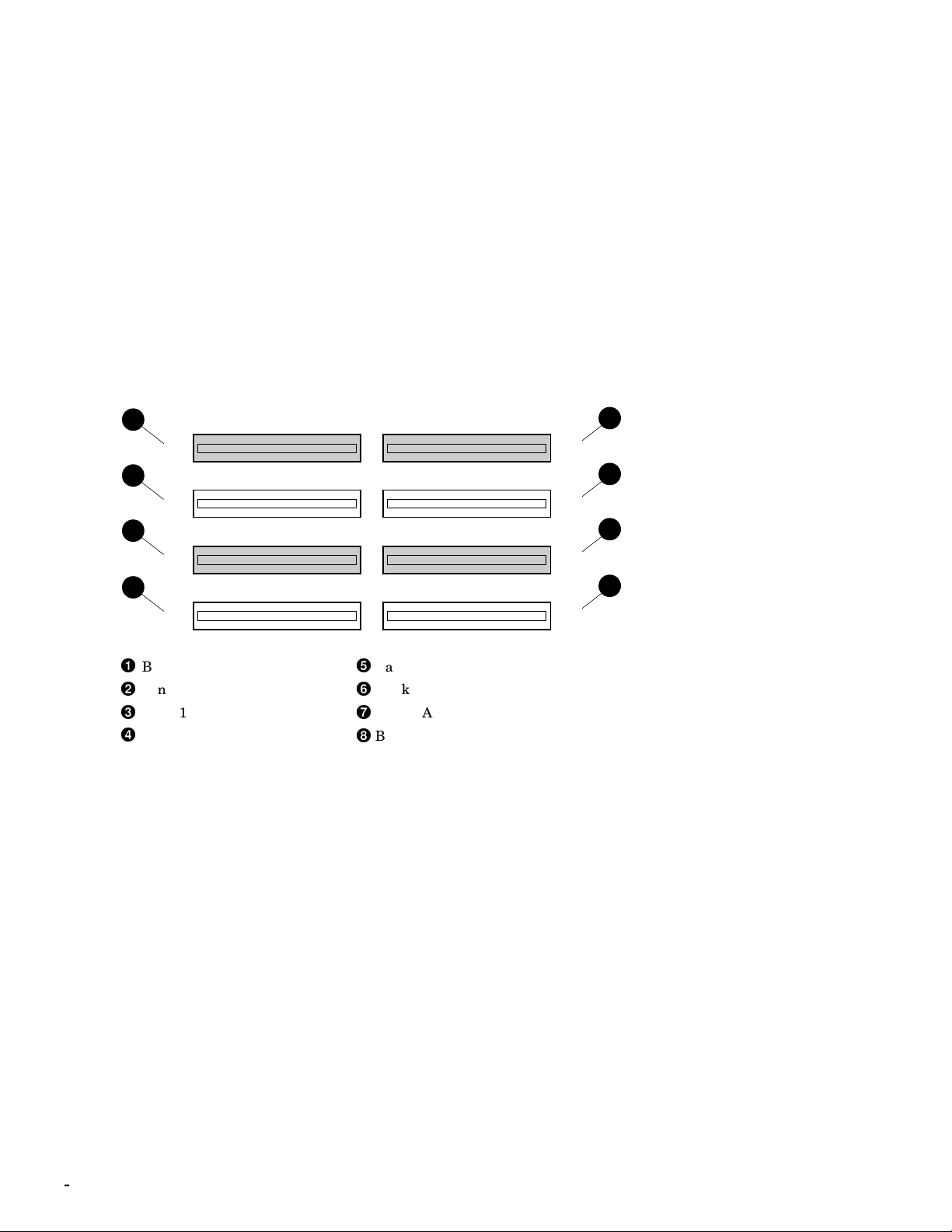
Figure 1–8 shows the banks of slots as they are viewed from the front of the
system. The ‘‘1’’ set of banks is shaded for identification.
Enclosure Description 1–13
Enclosure Description
1.5 Configuration Guidelines
Figure 1–8 Identifying Appropriate Banks of SIMM Connectors
1
5
3
7
Bank 1G
Bank 1H
Bank 1E
Bank 1F
1G
0C
1E
0A
Bank 0C
Bank 0D
Bank 0A
Bank 0B
2
1H
6
0D
4
1F
8
0B
MLO-012342
1–14 Enclosure Description

1.5.2 Communications Options
Table 1–3 lists the communications options that a BA42B Enclosure can
contain.
Table 1–3 BA42B Communications Options
Option Name Description
Asynchronous Options
DHW42-AA Provides 8 DEC423 asynchronous lines
DHW42-BA Provides 16 DEC423 asynchronous lines
DHW42-CA Provides 8 EIA-232 asynchronous modem lines
DHW42-UP 8 to 16 DEC423 asynchronous line upgrade
Synchronous Options
DSW42-AA
1
This option is supplied with two external cables that support the EIA-232/V.24 interface.
1
Provides two EIA-232/V.24 synchronous lines
Enclosure Description
1.5 Configuration Guidelines
The DSW42-AA option also supports the communications interfaces listed in
Table 1–4, but you must order the external cable separately.
Table 1–4 DSW42-AA Communications Interface Support
Communications Interface External Cable
EIA-423/V.10 BC19E-02
EIA-422/V.11 BC19B-02
Each communications option contains three field replaceable units (FRUs) that
are installed in the enclosure as follows:
• A logic board
The logic board connects directly to the CPU module.
• An input/output cable
The input/output cable connects the CPU module to the input/output
module.
• An input/output module
Enclosure Description 1–15
Enclosure Description
1.5 Configuration Guidelines
The input/output module is a snap-fit assembly that is attached to the
inside of the back panel of the BA42B Enclosure.
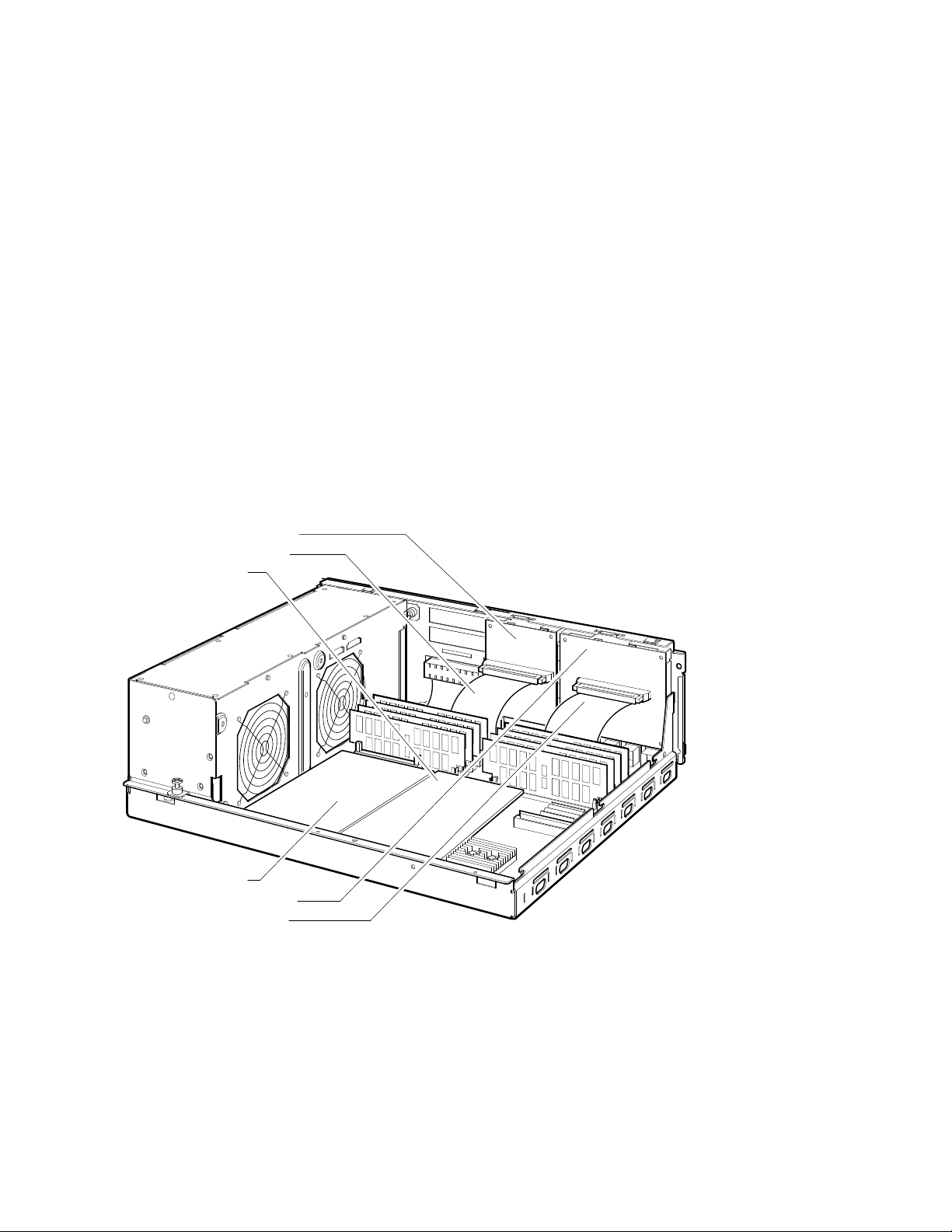
The communications options logic boards have different locations in the BA42B
Enclosure, depending on the model number of the system. The DHW42 logic
board is located to the left of the CPU module, with the DSW42 logic board
located to its right (see Figure 1–9; Model 100 is shown as an example).
Figure 1–9 Communications Options in Model 100/100A/105A Systems
DSW42 Input/Output Module
DSW42 Input/Output Cable
DSW42 Logic Board
DHW42 Logic Board
DHW42 Input/Output Module
DHW42 Input/Output Cable
1–16 Enclosure Description
MLO-009870
 Loading...