

Digital Equipment AlphaStation 600 Series User Information

AlphaStation 600 Series
User Information
Part Number: EK-AS800-UI. B01
June 1995
This book introduces the AlphaStation 600 Series system. Use the information in this
book to configure, start, use, update, and troubleshoot your system. You will also find
general system information, such as console commands and system care, in this book.
Revision/Update Information: First Revision.
Digital Equipment Corporation
Maynard, Massachusetts

June 1995
Digital Equipment Corporation makes no representations that the use of its products in the manner described in this
publication will not infringe on existing or future patent rights, nor do the descriptions contained in this publication
imply the granting of licenses to make, use, or sell equipment or software in accordance with the description.
Possession, use, or copying of the software described in this publication is authorized only pursuant to a valid
written license from Digital or an authorized sublicensor.
© Digital Equipment Corporation 1995. All rights reserved.
The postpaid Reader's Comments form at the end of this document requests your critical evaluation to assist in
preparing future documentation.
The following are trademarks of Digital Equipment Corporation: AlphaStation, ThinWire, and the DIGITAL logo.
The following are third-party trademarks:
Microsoft and Windows NT are registered trademarks of Microsoft Corporation.
SIMM is a trademark of Molex Corporation.
OSF/1 is a trademark of the Open Software Foundation, Inc.
All other trademarks and registered trademarks are the property of their respective holders.
[S2868]
ii

Information - Class B
This device complies with Part 15 of the FCC rules. Operation is subject to the following
conditions:
(1) this device may not cause harmful interference, and
(2) this device must accept any interference received, including interference that may
cause undesired operation.
This equipment has been tested and found to comply with the limits for a Class B digital
device, pursuant to Part 15 of the FCC rules. These limits are designed to provide
reasonable protection against harmful interference in a residential installation. Any
changes or modifications to this equipment may void the user's authority to operate this
equipment.
This equipment generates, uses, and can radiate radio frequency energy and, if not
installed and used in accordance with the instructions, may cause harmful interference to
radio communications. However, there is no guarantee that interference will not occur in a
particular installation. If this equipment does cause harmful interference to radio or
television reception, which can be determined by turning the equipment off and on, the
user is encouraged to try to correct the interference by one or more of the following
measures:
•
Reorient or relocate the receiving antenna.
•
Increase the separation between the equipment and the receiver.
•
Connect the equipment into an outlet on a circuit different from that to which the
receiver is connected.
Consult the dealer or an experienced radio/TV technician for help.
The keyboard and video ports should be connected only with shielded data cables with an
external ferrite bead over the cable. When either of these ports is connected with cables
without such a ferrite bead, the additional ferrite beads shall be clamped over these cables
next to the cable connector.
iii


Table of Contents
1 Getting Started............................................................................1-1
Introduction........................................................................................................... 1-1
Before Starting Your System................................................................................. 1-2
Posture and Work Habits................................................................................1-3
Identifying the Correct AC Power Cord.......................................................... 1-6
Installing Your System.......................................................................................... 1-7
Connecting System Components .................................................................... 1-9
Network Connection..................................................................................... 1-11
Starting Your System .......................................................................................... 1-11
Preloaded Operating System Software..........................................................1-12
DEC OSF/1 ........................................................................................... 1-13
OpenVMS .............................................................................................1-13
Switching Console Firmware........................................................................ 1-13
If No Operating System Is Installed..............................................................1-13
Turning Off Your System.................................................................................... 1-14
Computer Security .............................................................................................. 1-15
Security Lock............................................................................................... 1-15
Passwords.....................................................................................................1-15
2 System Overview ........................................................................2-1
Introduction........................................................................................................... 2-1
System Unit ..........................................................................................................2-1
PCI Architecture ................................................................................................... 2-2
AlphaStation 600 Series I/O Subsystem................................................................. 2-2
The Keyboard .......................................................................................................2-2
System Front Panel ...............................................................................................2-4
System Rear Panel ................................................................................................2-6
v

Table of Contents
3 Installing System Options......................................................... 3-1
Introduction .......................................................................................................... 3-1
System Unit Components...................................................................................... 3-2
Left Side Panel...................................................................................................... 3-3
Removing the Left Side Panel........................................................................ 3-3
Replacing the Left Side Panel ........................................................................ 3-5
System Board........................................................................................................ 3-6
System Memory....................................................................................................3-8
Cache Memory............................................................................................... 3-8
Random-Access Memory............................................................................... 3-8
Adding a SIMM to a Memory Tower ............................................................3-10
Replacing the Cache Memory Modules.........................................................3-13
External Drive Bay Devices.................................................................................3-14
SCSI Addresses.............................................................................................3-14
SCSI Termination .........................................................................................3-14
Installing External Drive Bay Devices...........................................................3-15
Internal Drive Bay Devices..................................................................................3-21
Removing the Drive Assembly from the System Unit....................................3-21
Removing a Device from the Drive Assembly...............................................3-23
Replacing the Drive Assembly in the System Unit ........................................3-24
ISA, EISA, and PCI Expansion Options...............................................................3-25
ISA Bus.........................................................................................................3-25
EISA Bus......................................................................................................3-26
PCI Bus.........................................................................................................3-26
Installing Expansion Modules .......................................................................3-27
The Operator Control Panel .................................................................................3-30
Rotating the OCP..........................................................................................3-30
4 Troubleshooting.........................................................................4-1
Introduction .......................................................................................................... 4-1
Initial Troubleshooting.......................................................................................... 4-1
General Troubleshooting....................................................................................... 4-2
Status and Error Codes.......................................................................................... 4-8
Equipment Log ..................................................................................................... 4-9
A Console Commands..................................................................A-1
Introduction ..........................................................................................................A-1
ARC Console........................................................................................................ A-1
Commands You Need to Know......................................................................A-2
Display Hardware Configuration.............................................................A-2
vi

Table of Contents
Set Default Environment Variables......................................................... A-2
Set Default Configuration....................................................................... A-2
Manage Boot Selection Menu................................................................. A-2
Machine Specific Setup.......................................................................... A-3
Boot (Boot Selection Identifier).............................................................. A-3
Boot an Alternate Operating System ....................................................... A-3
Other Commands of Interest.......................................................................... A-3
Setup Autoboot....................................................................................... A-3
Install New Firmware............................................................................. A-3
Install Windows NT from CD-ROM....................................................... A-4
Switch to OpenVMS or OSF Console..................................................... A-4
SRM Console....................................................................................................... A-5
SRM Console Conventions............................................................................ A-5
SRM Console Shortcut Keys ......................................................................... A-6
Boot Command ............................................................................................. A-7
Boot Command Examples ...................................................................... A-8
ECU Command............................................................................................. A-9
Set Command................................................................................................ A-9
Set Command Examples........................................................................A-10
Show Command...........................................................................................A-10
Show Command Examples....................................................................A-11
Environment Variables.................................................................................A-12
Examine Command......................................................................................A-13
Examine Command Examples...............................................................A-14
Deposit Command........................................................................................A-15
Deposit Command Examples.................................................................A-16
Using the EISA Configuration Utility..................................................................A-17
Before You Run the ECU.............................................................................A-17
Configuring EISA Options ...........................................................................A-18
Configuring ISA Options..............................................................................A-20
B System Care...............................................................................B-1
Introduction...........................................................................................................B-1
Cleaning Your System Unit................................................................................... B-1
Cleaning Your Monitor .........................................................................................B-1
Cleaning Your Mouse ...........................................................................................B-2
Cleaning Your Keyboard.......................................................................................B-3
Moving Your System ............................................................................................B-3
Packing Your System .....................................................................................B-4
Installing Your System at a New Location......................................................B-4
vii

Table of Contents
C Technical Specifications...........................................................C-1
Introduction ..........................................................................................................C-1
System Specifications ...........................................................................................C-1
External System Connectors..................................................................................C-3
Parallel Port Connector ..................................................................................C-4
Serial Port Connectors....................................................................................C-5
Keyboard and Mouse Connectors...................................................................C-5
SCSI Connectors............................................................................................C-6
Expansion Slots..............................................................................................C-8
Power Supply and Input Power Requirements.......................................................C-9
System Board Jumper Locations ......................................................................... C-10
I/O Subsystem Module........................................................................................C-13
SCSI Controller............................................................................................C-13
Ethernet Interface.........................................................................................C-14
Thick Wire Jumpering........................................................................... C-14
ThinWire or Twisted-pair Jumpering.....................................................C-14
Software Switches................................................................................. C-14
D Device Mapping .........................................................................D-1
Introduction ..........................................................................................................D-1
I/O Address Map...................................................................................................D-1
Interrupt Map........................................................................................................D-2
E Updating System Firmware.......................................................E-1
Introduction ..........................................................................................................E-1
System Firmware..................................................................................................E-1
Update Utility.......................................................................................................E-1
Flash Enable Jumper ......................................................................................E-1
Using the Flash Update Utility .......................................................................E-1
F Starting an Operating System Installation...............................F-1
Introduction .......................................................................................................... F-1
Starting a DEC OSF/1 Installation......................................................................... F-2
Starting an OpenVMS Installation......................................................................... F-3
viii

List of Figures
Figure 1-1. AlphaStation 600 Series System .......................................................... 1-2
Figure 1-2. Recommendations for Posture and Work Habits.................................. 1-4
Figure 1-3. System Airflow (Side View, Cover Removed) .................................... 1-8
Figure 1-4. Connecting Cables and the Power Cord............................................. 1-10
Figure 1-5. Starting Your System........................................................................ 1-12
Figure 2-1. Typical Keyboard Layout.................................................................... 2-3
Figure 2-2. Front Controls, Indicators, and Drive Bay Locations........................... 2-4
Figure 2-3. Rear Connectors (Rear View).............................................................. 2-6
Figure 3-1. System Unit Components.................................................................... 3-2
Figure 3-2. Unlocking and Removing the Left Side Panel..................................... 3-4
Figure 3-3. Replacing the Left Side Panel ............................................................. 3-5
Figure 3-4. System Board Components .................................................................3-7
Figure 3-5. Populating a Memory Tower............................................................... 3-9
Figure 3-6. Removing a Memory Tower.............................................................. 3-11
Figure 3-7. Installing a SIMM............................................................................. 3-12
Figure 3-8. Removing a Plastic Filler Panel......................................................... 3-15
Figure 3-9. Attaching the Securing Bracket and Installing the Device................. 3-17
Figure 3-10. SCSI and Removable Device Connector Cable Configuration......... 3-18
Figure 3-11. Power Cable Configuration ............................................................. 3-19
Figure 3-12. Removing the Drive Assembly ........................................................ 3-22
Figure 3-13. Removing a Device from the Drive Assembly................................. 3-23
Figure 3-14. ISA, EISA, and PCI Expansion Module Contacts............................ 3-25
Figure 3-15. EISA/ISA Slot Numbering .............................................................. 3-26
Figure 3-16. Installing an Expansion Module ...................................................... 3-28
Figure 3-17. Removing the Front Bezel............................................................... 3-30
Figure 3-18. Rotating the OCP............................................................................ 3-31
Figure B-1. Cleaning the Mouse............................................................................B-3
Figure C-1. System Board Jumper Locations.......................................................C-11
Figure C-2. I/O Subsystem Module Jumper/Connector Locations........................C-15
Table of Contents
ix

Table of Contents
List of Tables
Table 1-1. Recommendations for Posture and Work Habits................................... 1-4
Table 1-2. System Shutdown Commands .............................................................1-14
Table 2-1. Key Groups and Functions ................................................................... 2-3
Table 2-2. Front Controls, Indicators, and Drive Bay Locations............................ 2-4
Table 2-3. Rear Connectors................................................................................... 2-7
Table 3-1. System Unit Components..................................................................... 3-2
Table 3-2. System Board Components .................................................................. 3-7
Table 3-3. SCSI Address Recommendations ........................................................3-14
Table 4-1. System Troubleshooting....................................................................... 4-2
Table 4-2. Disk Drive Troubleshooting................................................................. 4-6
Table 4-3. Monitor Troubleshooting...................................................................... 4-7
Table 4-4. Status and Error Codes......................................................................... 4-8
Table A-1. SRM Console Conventions.................................................................. A-5
Table A-2. SRM Console Shortcut Keys ............................................................... A-6
Table A-3. Boot Command Examples...................................................................A-8
Table A-4. Set Command Examples....................................................................A-10
Table A-5. Show Command Examples................................................................A-11
Table A-6. Environment Variables ...................................................................... A-12
Table A-7. Examine Command Examples...........................................................A-14
Table A-8. Deposit Command Examples.............................................................A-16
Table C-1. System Specifications..........................................................................C-2
Table C-2. System Dimensions .............................................................................C-2
Table C-3. System Environmental Specifications ..................................................C-2
Table C-4. Acoustics-Declared Values According to ISO 9296 and ISO 7779.......C-3
Table C-5. Parallel Port Pinouts............................................................................C-4
Table C-6. 9-Pin Port Pinouts................................................................................C-5
Table C-7. Keyboard and Mouse Connector Pinouts .............................................C-5
Table C-8. Wide SCSI Pinouts..............................................................................C-6
Table C-9. Narrow SCSI Pinouts...........................................................................C-7
Table C-10. Output Power Requirements..............................................................C-9
Table C-11. Input Power Requirements.................................................................C-9
Table C-12. System Board Jumpers.....................................................................C-12
Table C-13. I/O Subsystem Module Jumpers.......................................................C-13
Table D-1. I/O Address Map.................................................................................D-1
Table D-2. Main Interrupt Logic IRQ Pin Assignments.........................................D-2
Table D–3. EISA Interrupt Assignments ...............................................................D-3
Table F-4. Starting a DEC OSF/1 Installation .......................................................F-2
Table F-5. Starting an OpenVMS Installation........................................................ F-3
Table G-1. Hardware Components.......................................................................G–2
Table G-2. SCSI Addresses..................................................................................G–2
Table G-3. Hardware Configuration.....................................................................G–3
x

Table of Contents
Table G-4. Installed Software...............................................................................G–3
Table G-5. Additional Component Information....................................................G–3
xi


Welcome to the AlphaStation 600 Series System
This book introduces the AlphaStation 600 Series system.
Use the information in this book to configure, start, use, update, and troubleshoot your
AlphaStation 600 Series system. You can also find general system information such as
console commands and system care in this book.
Audience
If you will be operating, configuring, or adding options to the AlphaStation 600 Series
system, the information included in this book will be helpful to you.
Organization of the Information
This information for users covers the following topics:
• • Chapter 1, Getting Started, describes installing, starting, restarting, and turning off the
system.
• Chapter 2, System Overview, describes the hardware components, including the
peripheral component interconnect (PCI) architecture, the controller, the keyboard, the
system unit front panel, and the system unit rear panel.
• Chapter 3, Installing System Options, describes the system unit components and gives
instructions and illustrations to help you remove and replace them.
Preface
• Chapter 4, Troubleshooting, describes system troubleshooting as well as the error beep
codes.
• Appendix A, Console Commands, contains a basic description of the advanced RISC
computing (ARC) console commands and the system reference manual (SRM) console
commands.
xiii

Preface
• Appendix B, System Care, describes how to clean your system, monitor, mouse, and
keyboard. It also contains instructions for moving and reinstalling your system.
•
Appendix C, Technical Specifications, describes the technical characteristics of the
system.
• Appendix D, Device Mapping, lists system device address mapping information,
including I/O addresses and interrupts.
•
Appendix E, Updating System Firmware, explains how to use the firmware update
utility.
•
Appendix F, Starting an Operating System Installation, provides the information you
need to begin an operating system installation.
•
Appendix G, Equipment Log, contains tables that you can use to record information
about your system hardware and software components.
Refer to the Table of Contents for a detailed listing of topics.
Conventions
This guide uses the following conventions:
Convention Example Description
c:\windowsc:\windows>
[Enter] Square brackets surrounding text represent a
[Ctrl]+[R] A plus sign between keyboard keys indicates
auto_action
F
Monospaced, bold text indicates file names,
path names, directories, or screen text.
key on the keyboard.
that the keys shown should be pressed at the
same time.
Italic text indicates environment variables.
Titles of information sources are in italic, and
occasionally italic is used for emphasis in the
text.
A pointing hand indicates a reference to
additional information.
xiv

Abbreviations
This guide uses the following abbreviations:
Abbreviation Meaning
AC alternating current
amp ampere
ARC advanced RISC computing (Windows NT console)
ARCINST ARC installation program
C Celsius
CD compact disc
CD-ROM compact disc read-only memory
CEE International Commission for Conformity Certification of
CFG configuration file
cm centimeters
CPU central processing unit
CSA Canadian Standards Association
DC direct current
DMA direct memory access
DRAM dynamic random-access memory
DROM diagnostic read-only memory
ECU EISA configuration utility
EISA extended industry-standard architecture
flashROM electrically erasable, rewriteable, nonvolatile memory
ft feet
GB gigabyte
Hz hertz
IEC International Electrotechnical Commission
I/O input/output
IRQ interrupt request
ISA industry-standard architecture
ISACFG ISA configuration file
ISO International Organization for Standardization
Preface
Electrical Equipment
xv

Preface
Abbreviation Meaning
Kb kilobit
KB kilobyte
kg kilogram
lb pound
LED light-emitting diode
m meter
MAU media adapter unit
Mb megabit
MB megabyte
MHz megahertz.
mm millimeter
ns nanoseconds
NVRAM nonvolatile random-access memory
OSF DEC Open Software Foundation/1 UNIX operating system
PCI peripheral component interconnect
RISC reduced instruction set computing
ROM read-only memory
SCSI small computer system interface
SIMM single in-line memory modules
SRM system reference manual (the DEC OSF/1 and OpenVMS
consoles)
SROM serial read-only memory
UL Underwriters Laboratories
VAR value-added reseller
V AC volts alternating current
VMS Virtual Memory System
W watt
xvi

Special Notices
This guide uses three kinds of notices to emphasize specific information.
________________________WARNING __________________________
A WARNING indicates the presence of a hazard that can cause personal
injury.
____________________________________________________________
________________________ CAUTION___________________________
A CAUTION indicates the presence of a hazard that can cause damage to
hardware or that might corrupt software.
____________________________________________________________
__________________________NOTE ____________________________
A NOTE gives general information, such as compatibility with other products or
pointers to other information.
____________________________________________________________
Preface
Additional Information Resources
You may wish to consult the following information resource for additional information
about your AlphaStation 600 Series system:
• AlphaStation 600 Series Installation Information (order number EK-AS800-IN), which
presents a graphical overview of the AlphaStation 600 Series system installation.
Contact your distributor or Digital representative for other available product-related
information.
xvii


Introduction
Your AlphaStation 600 Series is a high-performance system that uses the latest
microprocessor technology. The system can stand alone or function as a client in an office
network environment.
This chapter describes how to install, start, restart, and turn off your AlphaStation 600
Series system. You can also find information here about preloaded software as well as
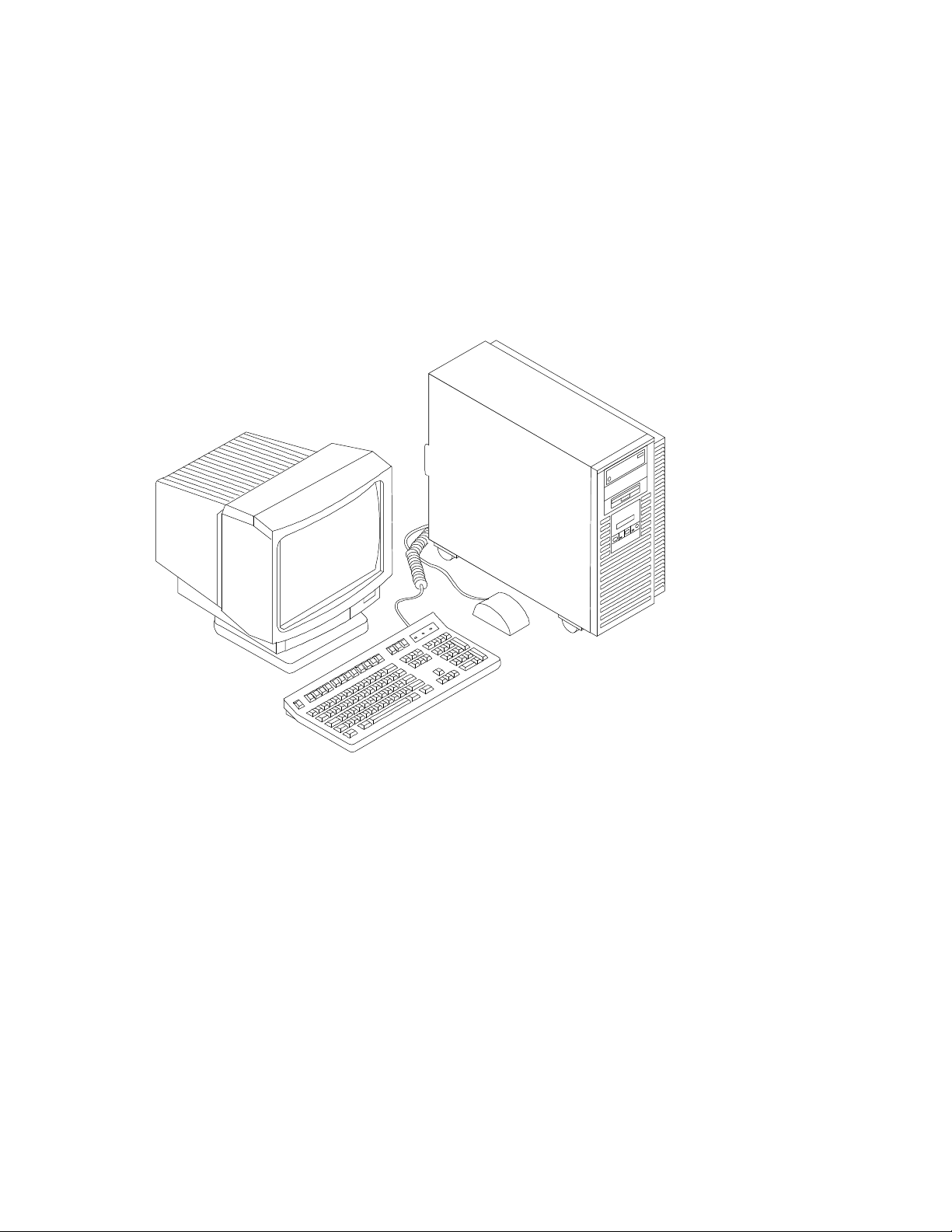
guidelines for system security. Figure 1-1 shows a typical AlphaStation 600 Series system.
1
Getting Started
1-1
Getting Started
Figure 1-1. AlphaStation 600 Series System
Before Starting Your System
Before you start your system, follow this procedure:
1. Read and understand the information supplied with your system.
2. Select a well-ventilated site near a grounded power outlet and away from sources of
excessive heat. Also, use an appropriate power strip to isolate the site from electric
noise (for example, spikes, sags, and surges) produced by devices such as air
conditioners, large fans, radios, and televisions.
3. Save all shipping containers and packing material for repackaging or moving the
system later.
1-2

_________________________ NOTES____________________________
• Do not install optional hardware or application software until you have
started your system and verified that the base system is working correctly.
• • On systems that have preloaded software, a label attached to the system unit
informs you that there is licensed software installed. Carefully review the
software license agreement shipped with your system.
____________________________________________________________
________________________WARNING __________________________
When unpacking and moving system components, be aware that some
components (such as the system unit or monitor) may be too heavy for you
to safely lift alone. If you are doubtful about whether you can lift these items
alone, please get assistance.
____________________________________________________________
Posture and Work Habits
If you use poor posture while you work or if your equipment is poorly positioned, personal
injury may result (as suggested by certain recent scientific articles). Although other articles
suggest that there is no cause and effect, we strongly recommend that you read and follow
the precautions outlined in Figure 1-2 and Table 1-1. In addition, be sure to adjust your
work area so that you are comfortable.
Getting Started
1-3
Getting Started
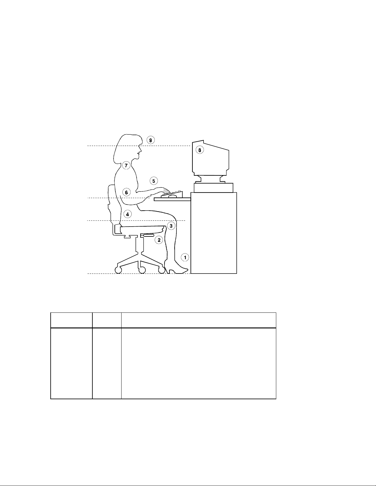
Figure 1-2. Recommendations for Posture and Work Habits
1-4
Table 1-1. Recommendations for Posture and Work Habits
Adjust Figure
Callout
Chair 1
2
3
4
To allow the following conditions:
Your feet are flat on the floor.
Your legs are vertical and form a right angle to the floor.
Your thighs are horizontal, and they are not bearing weight. To
prevent restriction of the blood flow, keep the backs of your
knees away from the seat so you do not compress the area
behind them.
Your upper body is erect and your lower back is supported with
a backrest.
Getting Started
Table 1-1. Recommendations for Posture and Work Habits
Adjust Figure
Callout
Keyboard and
Mouse
Head 7 Avoid neck strain. Your head should incline downward, but no
Monitor 8
Lighting Direct lighting or sunlight on the screen causes glare and
Noise Keep background noise at a minimum. Background noise above
Temperature The temperature should be between 20° and 23°C (68° and 74°
Humidity The humidity should be between 30% and 70%.
Ventilation Provide adequate air ventilation to operate the equipment and
Work Area Your work area should be greater than 70 cm (28 inches) center
5
6
9
To allow for the following conditions:
Your wrists are straight and do not flex more than 15 degrees.
They are supported and do not rest on sharp edges. If you use a
mouse, rest your hand on the mouse so your wrist is not on the
work surface. Operate the mouse close to your body's centerline.
Your upper arms are straight down at your sides, and your
elbows are close to your sides and support your arm weight.
Forearms are at a 70- to 90-degree angle.
more than 15 to 20 degrees.
The monitor should be no higher than the level of your eyes and
at the correct distance for your vision.
Avoid eye fatigue, which can be caused by glare, image quality,
uncomfortable furniture, eye height, and uncorrected vision. If
you cannot focus to read at different distances, you may need
special glasses. Relax your eyes periodically by focusing on
distant objects.
reflections. Place lighting behind or to the side of your work
area, and distribute the lighting evenly on your work area.
65 dBa is tiring. Sound-absorbing materials (for example,
curtains, carpeting, and acoustic tile) can help reduce
background noise.
F).
avoid fatigue.
to center, preferably 152 cm (60 inches).
(continued)
1-5

Getting Started
________________________WARNING___________________________
If you experience pain or discomfort while using your system, rest and
review the instructions for posture and work habits. If the pain or
discomfort continues after resuming work, discontinue use and report the
condition to your job supervisor or physician.
____________________________________________________________
Identifying the Correct AC Power Cord
The proper AC power cord accompanies your AlphaStation 600 Series system. Because
variations exist from one country to another, and systems may be moved, inspect your
power cord to ensure that it is the correct one for your country or region. If you are not
sure that the supplied AC power cord is correct, contact your authorized Digital service
representative or distributor before you use it.
________________________WARNING___________________________
Do not attempt to modify or use an external 115V AC power cord for 230V
AC input power. Modifying the power cord can cause personal injury and
severe equipment damage.
____________________________________________________________
1-6
Power cords supplied with the AlphaStation 600 Series system meet the following criteria:
• The cords are UL-listed and CSA-certified, rated for use at 250V AC with a current
rating that is at least 125% of the current rating of the AlphaStation 600 Series system.
In Europe, the cordage carries the <HAR> mark.
• The AC plug is terminated in a grounding-type male plug designed for use in the
region. It must also have marks showing certification by an agency acceptable in the
region.
• The connector at the computer end must be an IEC
1
-type CEE2-22 female connector.
• The cord length does not exceed 4.5 m (14.5 ft).
1
International Electrotechnical Commission.
2
International Commission for Conformity Certification of Electrical Equipment.

Installing Your System
The AlphaStation 600 Series Installation Information you received with your system
graphically outlines the steps to follow to install your system.
1. Make sure you received all of your system components. Use Appendix G, Equipment
Log, to list your equipment. If something is missing, please contact your distributor or
Digital representative.
2. If you are using rack-mount installation, remove the glide pads (enclosure feet).
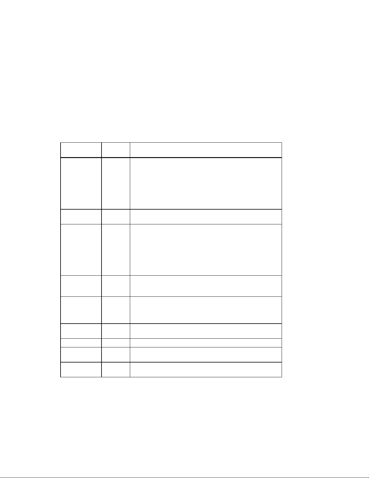
3. Position your system so that air can flow freely to and from the vents, as shown in
Figure 1-3.
________________________CAUTIONS __________________________
To ensure that your system is properly cooled:
• Make sure that air can freely flow into the front and out of the rear of
the system unit.
• Do not remove a filler plate until you are ready to add a new system
component.
____________________________________________________________
Getting Started
1-7
Getting Started
Rear of system unit
Front of system unit
Figure 1-3. System Airflow (Side View, Cover Removed)
1-8

Connecting System Components
To connect the components of your AlphaStation 600 Series system, follow this procedure:
__________________________NOTE ____________________________
The AlphaStation 600 Series system runs on 88V–268V AC and 48–62 Hz. The
system uses an autosensing power supply.
____________________________________________________________
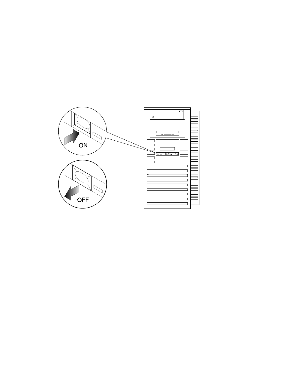
1. Ensure that the On/Off switch is in the Off (flush) position. See Figure 1-5 for a view
of the switch positions.
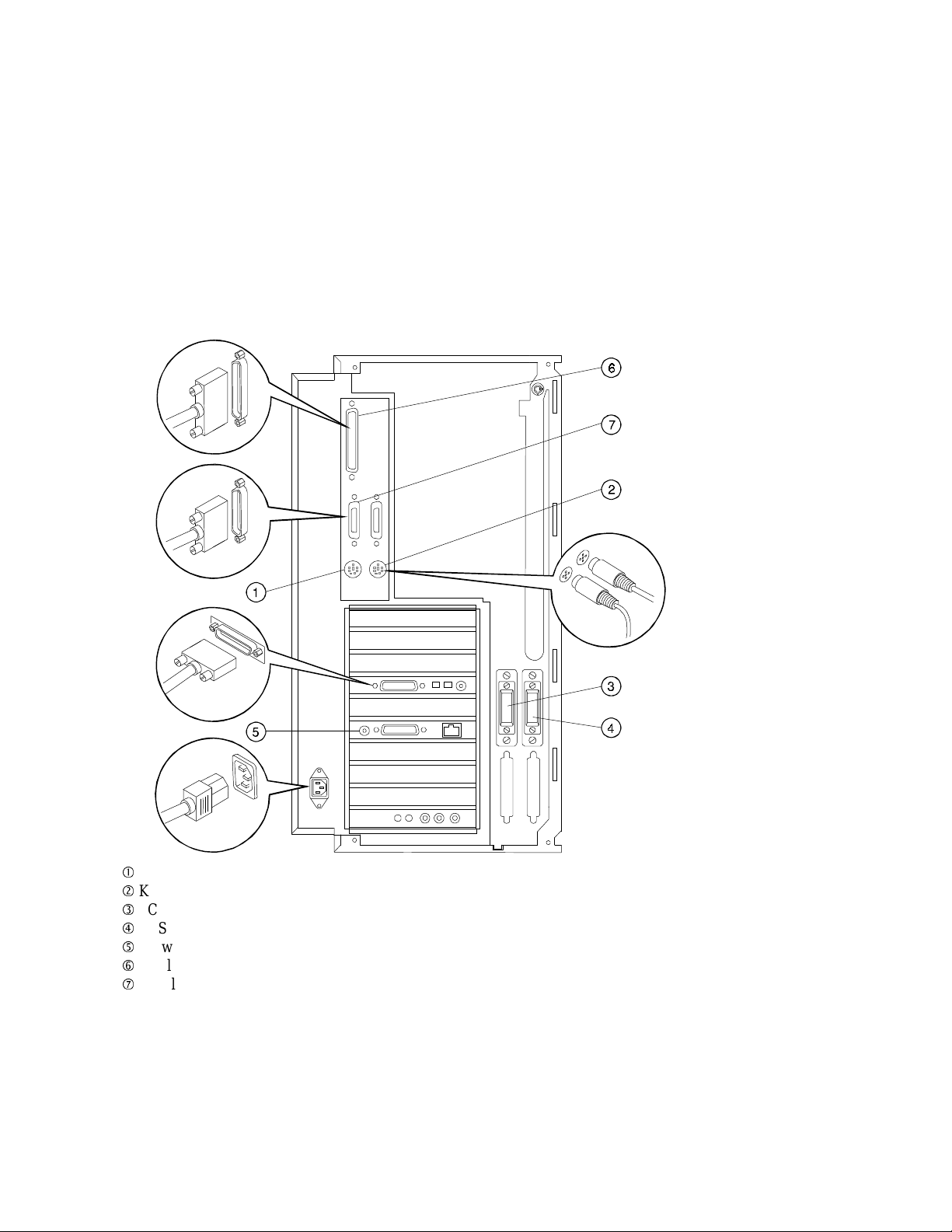
2. Connect the mouse, keyboard, video cable, and power cords to the system
components, as shown in Figure 1-4. There are two SCSI external expansion ports in
the lower-right rear panel: a 50-pin (narrow) and a 68-pin (wide). Install the 50-pin
and 68-pin terminators supplied with the systemif you are not going to use these
expansion ports
__________________________NOTE ____________________________
If you disconnect the mouse or keyboard during operation, data will be lost and
you will have to power-cycle the entire system.
____________________________________________________________
Getting Started
1-9
Getting Started
1-10
Mouse connector
Keyboard connector
SCSI bus connector - 50-pin (narrow)
SCSI bus connector - 68-pin (wide)
Network connectors
Parallel port
Serial ports
Figure 1-4. Connecting Cables and the Power Cord

3. If you have an external small computer system interface (SCSI) interface or SCSI
storage box, connect the SCSI cable to the appropriate SCSI port on the rear of the
system. See the section on SCSI Termination in Chapter 3 for additional information.
Network Connection
The AlphaStation 600 Series I/O subsystem module has thick-wire, ThinWire, and twistedpair connectors for connecting to a network. Use the appropriate connector for your
application. The I/O subsystem module is factory-configured for ThinWire Ethernet. Refer
to Appendix C for additional information on the I/O subsystem.
Starting Your System
Perform the following steps to start your AlphaStation 600 Series system:
1. Turn on the system unit, monitor power, and any external devices. Figure 1-5 shows
the location of the system unit On/Off button.
2. If necessary, adjust the monitor contrast and brightness to obtain a readable screen
display. Refer to the information supplied with your monitor for further instructions.
3. Allow your system to complete any power-on self tests and device initialization
messages. This will take approximately 1 minute. If you are using the DEC OSF/1 or
OpenVMS operating systems, and the auto_action environment variable is set to
Boot, the system starts as soon as the self tests have completed (less than 2 minutes).
If you are using Windows NT, the operating system starts after a countdown expires
(default is 10 seconds).
Getting Started
1-11
Getting Started
Figure 1-5. Starting Your System
Preloaded Operating System Software
Your AlphaStation 600 Series system comes with one of the following operating systems
preloaded:
• DEC OSF/1
• OpenVMS
__________________________NOTE ____________________________
Windows NT is available but is not preloaded on your AlphaStation 600 Series
system.
____________________________________________________________
Depending on how the environment variables are set, your system shows one of the
operating system-specific displays described next, after the self tests complete
successfully.
1-12
 Loading...