

Digital Equipment AlphaStation 500 Series User Information

AlphaStation 500 Series
User Information
Part Number: EK-ALPH5-UI. B01
January 1997
This book introduces the AlphaStation 500 Series system. Use the information in this
book to configure, start, use, update, and troubleshoot your system. You will also find
general system information, such as console commands and system care, in this book.
Revision/Update Information: This is revision.
Digital Equipment Corporation
Maynard, Massachusetts

First Printing, December 1995
Revised, January 1997
Digital Equipment Corporation makes no representations that the use of its products in the manner described in this
publication will not infringe on existing or future patent rights, nor do the descriptions contained in this publication
imply the granting of licenses to make, use, or sell equipment or software in accordance with the description.
Possession, use, or copying of the software described in this publication is authorized only pursuant to a valid
written license from Digital or an authorized sublicensor.
© Digital Equipment Corporation 1995, 1997. All rights reserved.
The following are trademarks of Digital Equipment Corporation: AlphaStation, Digital UNIX, OpenVMS,
ThinWire, and the DIGITAL logo.
The following are third-party trademarks:
Microsoft and Windows NT are registered trademarks of Microsoft Corporation.
SIMM is a trademark of Molex Corporation.
UNIX is a registered trademark in the United States and other countries, licensed exclusively through X/Open
Company Ltd.
All other trademarks and registered trademarks are the property of their respective holders.
[S3420]

FCC CLASSIFICATION
There are many variants of AlphaStation 500 Series systems. Your AlphaStation 500
Series system may be classified as either a Class A or a Class B FCC/EMC device,
depending upon its options and configuration.. To determine your system’s classification,
look at the FCC Classification Label on the bottom of the system.
FCC NOTICE -- CLASS A DEVICE
The equipment described in this manual generates, uses, and may emit radio frequency
energy. The equipment has been type tested and found to comply with the limits for a
Class A digital device pursuant to part 15 of FCC Rules, which are designed to provide
reasonable protection against such radio frequency interference.
Operation of this equipment in a residential area may cause interference, in which case the
user at their own expense will be required to take whatever measures are required to
correct the interference. If shielded cables have been supplied or specified, they must be
used on the system in order to maintain international regulatory compliance.
FCC NOTICE -- CLASS B DEVICE
This device complies with Part 15 of the FCC rules. Operation is subject to the following
conditions:
(1) this device may not cause harmful interference, and
(2) this device must accept any interference received, including interference that may
cause undesired operation.
This equipment has been tested and found to comply with the limits for a Class B digital
device, pursuant to Part 15 of the FCC rules. These limits are designed to provide
reasonable protection against harmful interference in a residential installation. Any
changes or modifications to this equipment may void the user's authority to operate this
equipment.

FCC NOTICE -- CLASS B DEVICE (continued)
This equipment generates, uses, and can radiate radio frequency energy and, if not
installed and used in accordance with the instructions, may cause harmful interference to
radio communications. However, there is no guarantee that interference will not occur in a
particular installation. If this equipment does cause harmful interference to radio or
television reception, which can be determined by turning the equipment off and on, the
user is encouraged to try to correct the interference by one or more of the following
measures:
• Reorient or relocate the receiving antenna.
• Increase the separation between the equipment and the receiver is connected.
• Connect the equipment into an outlet on a circuit different from that to which the
receiver is connected.
Consult the dealer or an experienced radio/TV technician for help.
The keyboard and video ports should be connected only with shielded data cables with an
external ferrite bead over the cable. When either of these ports is connected with cables
without such a ferrite bead, the additional ferrite beads shall be clamped over these cables
next to the cable connector.

Table of Contents
1 System Overview
Introduction........................................................................................................................... 1-1
System Unit...........................................................................................................................1-2
Enclosure Front Panel............................................................................................................1-3
Enclosure Rear Panel.............................................................................................................1-4
The Keyboard........................................................................................................................1-6
2 Getting Started
Introduction........................................................................................................................... 2-1
Before Starting Your System.................................................................................................2-2
Identifying the Correct AC Power Cord..........................................................................2-3
Installing Your System ..........................................................................................................2-4
Connecting System Components.....................................................................................2-5
Network Connection.......................................................................................................2-7
Starting Your System.............................................................................................................2-7
Preloaded Operating System Software ............................................................................2-8
Digital UNIX...........................................................................................................2-8
OpenVMS................................................................................................................2-8
Switching Console Firmware..........................................................................................2-9
If No Operating System Is Installed ................................................................................2-9
Turning Off Your System......................................................................................................2-9
Computer Security...............................................................................................................2-10
Security Lock ...............................................................................................................2-10
Passwords.....................................................................................................................2-10
Posture and Work Habits ..............................................................................................2-10
AlphaStation 500 Series User Information v

Table of Contents
3 Installing System Options
Introduction...........................................................................................................................3-1
Top Cover/Left Side Panel ....................................................................................................3-2
Removing the Top Cover and Left Side Panel ................................................................3-2
System Unit Components ......................................................................................................3-4
System Board........................................................................................................................3-6
System Memory....................................................................................................................3-8
Cache Memory...............................................................................................................3-8
Memory Configuration Rules .........................................................................................3-8
Adding or Removing Memory Modules (DIMMs)..........................................................3-9
Storage Devices...................................................................................................................3-11
General Information on Installing Drives............................................................................. 3-11
SCSI Addresses (SCSI ID’s).........................................................................................3-11
SCSI Termination......................................................................................................... 3-12
External SCSI Connector Termination.......................................................................... 3-12
Internal SCSI Termination............................................................................................ 3-12
SCSI Bus Length..........................................................................................................3-12
Installing Optional Internal Storage Devices........................................................................3-13
Installing Hard Disk Drives in the Lower Right Side Inner Bay....................................3-13
Removing the CD-ROM........................................................................................ 3-14
Removing the Drive Tray from the Lower Right Side Inner Bay .................................. 3-15
Installing Drives In the Right Side Bracket...................................................................3-16
Installing a Hard Disk Drive in the Left Side Storage Bay............................................ 3-24
Removing the Floppy Drive Tray Assembly................................................................. 3-24
Removing the Floppy Drive from the Original Drive Tray ..................................... 3-26
Removing the Floppy Drive from the Drive Tray (Re-Designed)...........................3-27
Installing an Optional Hard Drive in the Original Left-side Drive Tray..................3-28
Installing an Optional Hard Drive in the Re-designed Left-side Drive Tray ........... 3-29
Installing an Optional Tape Drive in the Redesigned Left-Side Drive Tray............ 3-30
Replacing the Drive Tray Assembly in the System ....................................................... 3-30
PCI Expansion Options........................................................................................................3-31
PCI Bus........................................................................................................................3-31
Installing Expansion Modules....................................................................................... 3-32
Replacing the Left Side Panel and Top Cover ..................................................................... 3-34
Connecting External Options............................................................................................... 3-36
Connecting a Printer or Other Parallel Device .............................................................. 3-36
Connecting an External SCSI Option............................................................................ 3-36
vi
AlphaStation 500 Series User Information

Table of Contents
4 Troubleshooting
Introduction........................................................................................................................... 4-1
Initial Troubleshooting ..........................................................................................................4-1
General Troubleshooting .......................................................................................................4-2
SROM Status and Error Codes...............................................................................................4-8
Equipment Log.................................................................................................................... 4-10
Appendix
A Console Commands
Introduction..........................................................................................................................A-1
ARC Console........................................................................................................................A-1
Commands You Need to Know......................................................................................A-2
Display Hardware Configuration.............................................................................A-2
Set Default Environment Variables.........................................................................A-2
Set Default Configuration .......................................................................................A-3
Setting the Date and Time.......................................................................................A-4
Selecting a Default Language .................................................................................A-4
Manage Boot Selection Menu.................................................................................A-5
Machine Specific Setup ..........................................................................................A-6
Setting PCI Parity...................................................................................................A-7
Boot (Boot Selection Identifier)..............................................................................A-7
Boot an Alternate Operating System.......................................................................A-7
Other Commands of Interest..........................................................................................A-7
Setup Autoboot.......................................................................................................A-7
Install New Firmware..............................................................................................A-8
Install Windows NT from CD-ROM .......................................................................A-8
Switch to OpenVMS or Digital UNIX Console .......................................................A-8
SRM Console .......................................................................................................................A-8
SRM Console Conventions............................................................................................A-9
SRM Console Shortcut Keys........................................................................................ A-10
Boot Command............................................................................................................A-11
Boot Command Examples..................................................................................... A-12
Set Command..............................................................................................................A-13
Set Command Examples.......................................................................................A-14
Show Command ..........................................................................................................A-14
AlphaStation 500 Series User Information
vii

Table of Contents
Show Command Examples ................................................................................... A-15
Environment Variables................................................................................................ A-16
Examine Command..................................................................................................... A-17
Examine Command Examples.............................................................................. A-18
Deposit Command....................................................................................................... A-19
Deposit Command Examples................................................................................ A-20
B System Care
Introduction.......................................................................................................................... B-1
Cleaning Your System Unit.................................................................................................. B-1
Cleaning Your Monitor ........................................................................................................ B-1
Cleaning Your Mouse........................................................................................................... B-2
Cleaning Your Keyboard...................................................................................................... B-3
Moving Your System............................................................................................................ B-3
Packing Your System .................................................................................................... B-3
Installing Your System at a New Location..................................................................... B-3
C Technical Specifications
Introduction.......................................................................................................................... C-1
System Specifications........................................................................................................... C-1
External System Connectors................................................................................................. C-3
Parallel Port Connector.................................................................................................. C-4
Serial Port Connectors................................................................................................... C-5
Keyboard and Mouse Connectors .................................................................................. C-5
SCSI Connectors ........................................................................................................... C-6
Expansion Slots............................................................................................................. C-8
Power Supply and Input Power Requirements ...................................................................... C-9
System Board Jumper Locations......................................................................................... C-10
SROM Selection Jumpers............................................................................................ C-12
Ethernet Interface........................................................................................................ C-13
Software Switches ................................................................................................ C-13
Selecting the ThickWire/ThinWire or Twisted Pair Ports...................................... C-13
D Device Mapping
Introduction.......................................................................................................................... D-1
I/O Address Map..................................................................................................................D-1
Interrupt Map....................................................................................................................... D-2
viii
AlphaStation 500 Series User Information

Table of Contents
E Updating System Firmware
Introduction.......................................................................................................................... E-1
System Firmware.................................................................................................................. E-1
Update Utility....................................................................................................................... E-1
Flash Enable Jumper...................................................................................................... E-1
Using the Flash Update Utility....................................................................................... E-1
F Starting an Operating System Installation
Introduction...........................................................................................................................F-1
Starting a Windows NT Workstation Installation...................................................................F-2
Starting a Digital UNIX Installation ......................................................................................F-5
Starting an OpenVMS Installation .........................................................................................F-6
G Sound Card Overview
Introduction..........................................................................................................................G-1
Module Layout.....................................................................................................................G-1
Module Connectors........................................................................................................G-2
Module Jumpers ............................................................................................................G-3
External Connection Jacks.............................................................................................G-4
Software ........................................................................................................................G-4
Microsoft Windows NT Workstation Operating System.................................................G-4
Digital UNIX Operating System ....................................................................................G-4
OpenVMS Operating System.........................................................................................G-5
H Equipment Log
Introduction......................................................................................................................... H–1
Equipment Log.................................................................................................................... H–1
AlphaStation 500 Series User Information
ix

Table of Contents
List of Figures
Figure 1-1 Front Controls, Indicators, and Drive Bay Locations...........................1-3
Figure 1-2 Rear Connectors (Rear View)............................................................. 1-4
Figure 1-3 Typical Keyboard Layout.................................................................... 1-6
Figure 2-1 AlphaStation 500 Series System..........................................................2-2
Figure 2-2 System Enclosure Airflow...................................................................2-4
Figure 2-3 Voltage Select Switch ......................................................................... 2-5
Figure 2-4 Connecting Cables and the Power Cord............................................... 2-6
Figure 2-5 Starting Your System .......................................................................... 2-7
Figure 2-6 Recommendations and Posture and Work Habits................................ 2-11
Figure 3-1 Unlocking the Top Cover....................................................................3-2
Figure 3-2 Removing the Top Cover and Left Side Panel.....................................3-3
Figure 3-3 System Unit Components....................................................................3-4
Figure 3-4 System Board Components..................................................................3-6
Figure 3-5 DIMM Bank Configuration .................................................................3-9
Figure 3-6 Installing a DIMM.............................................................................3-10
Figure 3-7 Removing the CD-ROM Bracket....................................................... 3-14
Figure 3-8 Removing the Hard Drive Tray Bracket ............................................ 3-15
Figure 3-9 Installing Drives in the Right Side Bracket ........................................ 3-16
Figure 3-10 Cabling the Optional Hard Drives.................................................... 3-17
Figure 3-11 FDI/SCSI Cable Routing.................................................................3-18
Figure 3-12 Audio Cable Routing....................................................................... 3-20
Figure 3-13 Power Cable Configuration .............................................................3-21
Figure 3-14 MAU Cable Configurations............................................................. 3-22
Figure 3-15 Fan and LED Cable Connections ..................................................... 3-23
Figure 3-16 Removing the Floppy Drive Tray Assembly.................................... 3-25
Figure 3-17 Removing the Floppy Drive (Original Tray) .................................... 3-26
Figure 3-18 Removing the Floppy Drive (Re-designed Tray) ............................. 3-27
Figure 3-19 Installing the Hard Drive in the Original Left-side Drive Tray......... 3-28
Figure 3-20 Installing Optional Hard Drive (Re-designed Tray) ......................... 3-29
Figure 3-21 Installing a Tape Drive in the Redesigned Left-side Drive Tray ...... 3-30
Figure 3-22 PCI Option Slots.............................................................................. 3-31
Figure 3-23 Installing an Expansion Module ...................................................... 3-33
Figure 3-24 Replacing the Top Cover ................................................................. 3-35
Figure B-1 Cleaning the Mouse............................................................................ B-2
Figure C-1 System Board Jumper Locations........................................................C-11
Figure G-1 Card Connectors and Jumpers............................................................. G-1
x
AlphaStation 500 Series User Information

List of Tables
Table 1-1 Front Control, Indicators, and Drive Bay Locations..............................1-3
Table 1-2 Rear Connectors ...................................................................................1-5
Table 1-3 Key Groups and Functions....................................................................1-7
Table 2-1 System Shutdown Commands............................................................. 2-10
Table 2-2 Recommendations for Posture and Work Habits.................................2-11
Table 3-1 System Unit Components......................................................................3-5
Table 3-2 System Board Components...................................................................3-7
Table 3-3 SCSI Address Recommendations........................................................3-11
Table 3-4 PCI Option Slot Locations.................................................................. 3-31
Table 4-1 System Troubleshooting (continued)......................................................4-3
Table 4-1 System Troubleshooting (continued)......................................................4-4
Table 4-1 System Troubleshooting (continued)......................................................4-5
Table 4-3 Monitor Troubleshooting......................................................................4-7
Table 4-4 Status and Error Codes .........................................................................4-8
Table 4-4 Status and Error Codes (continued)........................................................4-9
Table A-1 SRM Console Convention................................................................... A-9
Table A-2 SRM Console Shortcut Keys.............................................................. A-10
Table A-3 Boot Command Examples.................................................................A-12
Table A-4 Set Command Examples................................................................... A-14
Table A-5 Show Command Examples ............................................................... A-15
Table A-6 Environmental Variables...................................................................A-16
Table A-7 Examine Command Examples .......................................................... A-18
Table A-8 Deposit Command Examples............................................................ A-20
Table C-1 System Specifications ......................................................................... C-1
Table C-2 System Dimensions............................................................................. C-2
Table C-3 System Environmental Specifications ................................................. C-2
Table C-4 Acoustics - Declared Values According to ISO 9296 and ISO 7779 .... C-3
Table C-5 Parallel Port Pinouts............................................................................ C-4
Table C-6 9-Pin Port Pinouts ............................................................................... C-5
Table C-7 Keyboard and Mouse Connector Pinouts............................................. C-5
Table C-8 Wide SCSI Pinouts.............................................................................. C-6
Table C-8 Wide SCSI Pinouts (Continued).......................................................... C-7
Table C-9 Narrow SCSI Pinouts (Continued)....................................................... C-8
Table C-10 Output Power Requirements.............................................................. C-9
Table C-11 Input Power Requirements ................................................................ C-9
Table C-12 System Board Jumpers.................................................................... C-12
Table C-13 SROM Selection Jumpers................................................................ C-12
Table D-1 I/O Address Map.................................................................................D-1
Table D-2 Main Interrupt Logic IRQ Pin Assignments ........................................D-3
Table of Contents
AlphaStation 500 Series User Information
xi

Table of Contents
Table D-3 EISA Interrupt Assignments ............................................................... D-4
Table D-4 Interrupt Jumpers................................................................................ D-4
Table F-1 Starting a Windows NT Workstation Installation..................................F-3
Table F-2 Setting Up Partitions for a Windows NT Workstation Installation........F-4
Table F-3 Starting a Digital UNIX Installation.....................................................F-5
Table F-4 Starting an Open VMS Installation.......................................................F-6
Table G-1 Card Connector and Jumpers .............................................................. G-2
Table G-2 Speaker Connector Pinouts................................................................. G-2
Table G-3 CD Connector Pinouts ........................................................................ G-3
Table G-4 TCE Jumper ........................................................................................ G-3
Table G-5 SW1 and SW2 Jumpers Audio Module Base Address......................... G-3
Table H-1 Hardware Components........................................................................H–2
Table H-2 SCSI Addresses ..................................................................................H–2
Table H-3 Hardware Configuration .....................................................................H–3
Table H-4 Installed Software...............................................................................H–3
Table H-5 Additional Component Information ....................................................H–3
xii
AlphaStation 500 Series User Information

Preface
Welcome to the Digital AlphaStation 500 Series System
This book introduces the Digital AlphaStation 500 Series system.
Use the information in this book to configure, start, use, update, and troubleshoot your
Digital AlphaStation 500 Series system. You can also find general system information
such as console commands and system care in this book.
Audience
If you will be operating, configuring, or adding options to the Digital AlphaStation 500
Series system, the information included in this book will be helpful to you.
Organization of the Information
This information for users covers the following topics:
• Chapter 1, System Overview, describes the hardware components, including the
peripheral component interconnect (PCI) architecture, the controller, the keyboard, the
system unit front panel, and the system unit rear panel.
• • Chapter 2, Getting Started, describes installing, starting, restarting, and turning off the
system.
• Chapter 3, Installing System Options, describes the system unit components and gives
instructions and illustrations to help you remove and replace them.
• Chapter 4, Troubleshooting, describes system troubleshooting as well as the error beep
codes.
• Appendix A, Console Commands, contains a basic description of the advanced RISC
computing (ARC) console commands and the system reference manual (SRM) console
commands.
AlphaStation 500 Series User Information xiii
Preface
• Appendix B, System Care, describes how to clean your system, monitor, mouse, and
keyboard. It also contains instructions for moving and reinstalling your system.
•
Appendix C, Technical Specifications, describes the technical characteristics of the
system.
• Appendix D, Device Mapping, lists system device address mapping information,
including I/O addresses and interrupts.
•
Appendix E, Updating System Firmware, explains how to use the firmware update
utility.
•
Appendix F, Starting an Operating System Installation, provides the information you
need to begin an operating system installation.
•
Appendix G, Sound Card Overview, describes the Digital AlphaStation 500 Series
system sound card.
•
Appendix H, Equipment Log, contains tables that you can use to record information
about your system hardware and software components.
Refer to the Table of Contents for a detailed listing of topics.
Conventions
This guide uses the following conventions:
Convention Example Description
c:\windowsc:\windows>
[Enter] Square brackets surrounding text represent a key on
[Ctrl]+[R] A plus sign between keyboard keys indicates that
auto_action
)
xiv
AlphaStation 500 Series User Information
Monospaced, bold text indicates file names, path
names, directories, or screen text.
the keyboard.
the keys shown should be pressed at the same time.
Italic text indicates environment variables. Titles of
information sources are in italic, and occasionally
italic is used for emphasis in the text.
A pointing hand indicates a reference to additional
information.

Abbreviations
This guide uses the following abbreviations:
Abbreviation Meaning
AC alternating current
amp ampere
ARC advanced RISC computing (Windows NT console)
ARCINST ARC installation program
C Celsius
CD compact disc
CD-ROM compact disc read-only memory
CEE International Commission for Conformity Certification of
CFG configuration file
cm centimeters
CPU central processing unit
CSA Canadian Standards Association
DC direct current
DIMMs dual in-line memory modules
DMA direct memory access
DRAM dynamic random-access memory
ECU EISA configuration utility
EISA extended industry-standard architecture
FDI Floppy Drive Interconnect
flashROM electrically erasable, rewriteable, nonvolatile memory
ft feet
GB gigabyte
Hz hertz
IEC International Electrotechnical Commission
I/O input/output
IRQ interrupt request
ISA industry-standard architecture
ISACFG ISA configuration file
ISO International Organization for Standardization
Preface
Electrical Equipment
AlphaStation 500 Series User Information
xv

Preface
Abbreviation Meaning
Kb kilobit
KB kilobyte
kg kilogram
lb pound
LED light-emitting diode
m meter
MAU media adapter unit
Mb megabit
MB megabyte
MHz megahertz.
mm millimeter
ns nanoseconds
NVRAM nonvolatile random-access memory
OSF DEC Open Software Foundation/1 UNIX operating system
PCI peripheral component interconnect
RISC reduced instruction set computing
ROM read-only memory
SCSI small computer system interface
SIMMs single in-line memory modules
SRM system reference manual (the Digital UNIX and OpenVMS
consoles)
SROM serial read-only memory
UL Underwriters Laboratories
VAR value-added reseller
V AC volts alternating current
VMS Open VMS Operating System
W watt
xvi
AlphaStation 500 Series User Information

Special Notices
This guide uses three kinds of notices to emphasize specific information.
________________________WARNING __________________________
A WARNING indicates the presence of a hazard that can cause personal
injury.
____________________________________________________________
________________________ CAUTION___________________________
A CAUTION indicates the presence of a hazard that can cause damage to
hardware or that might corrupt software.
____________________________________________________________
__________________________NOTE ____________________________
A NOTE gives general information, such as compatibility with other products or
pointers to other information.
____________________________________________________________
Preface
Additional Information Resources
You may wish to consult the following information resource for additional information
about your AlphaStation 500 Series system.
• AlphaStation 500 Series Installation Information (order number EK-ALPH5-IN),
which presents a graphical overview of the AlphaStation 500 Series system
installation.
Contact your distributor or Digital representative for other available product-related
information or visit the Digital WorkStation web site.
• Digital WorkStation Web Page - http://www.workstation.com/text.html
AlphaStation 500 Series User Information
xvii

Preface
Reader’s Comments
Digital welcomes your comments on this or any other manual. You can send your
comments to Digital in the following ways:
• Internet electronic mail to: readers_comments@zk3.dec.com
• Mail:
Digital Equipment Corporation
Shared Engineering Services
129 Parker Street - PKO3-2/21J
Maynard, MA 01754-2199
Please reference order number EK-ALPH5-UI. B01 in your correspondence.
xviii
AlphaStation 500 Series User Information

Introduction
Congratulations on your purchase of the AlphaStation 500 Series System. The
AlphaStation 500 Engineering team is very proud of this product and you can be assured
that this machine has been designed and tested with the utmost attention to performance
and reliability. It can run OpenVMS, Digital UNIX, or Windows NT. Your machine’s
performance range can be extended by the addition of memory, PCI cards, video upgrades,
and hard disk drives.
The AlphaStation 500 Series is a high-performance system that uses the latest
microprocessor technology. The system can stand alone or function as a client in an office
network environment. This chapter describes the AlphaStation 500 Series system hardware
components, including the peripheral component interconnect (PCI) architecture, the
keyboard, the system unit front panel, and the system unit rear panel.
Following the information provided here will assure safe and proper operation of your
AlphaStation 500 Series System.
1
System Overview
AlphaStation 500 Series User Information 1-1

System Overview
System Unit
Your AlphaStation 500 Series system uses a high-performance Alpha architecture CPU.
The system unit includes:
• Two accessible I/O bays: one for 3.5 inch x 1 inch floppy disk or 3.5 inch tape devices
and one for 5.25 inch x 1.6 inch CD-ROM
• Two non-accessible I/O bays: one that can accommodate a single 3.5 inch x 1.6 inch
device or two 3.5 x 1 inch devices. The bay below the floppy drive will accommodate
a single 3.5 inch x 1.6 inch hard drive (not available with tape option).
• Diskette controller that supports one diskette drive
• Integrated PCI-based SCSI-2 controller with Direct Memory Access and external
SCSI-2 connector that supports up to five SCSI devices. Initial offerings of the
AlphaStation 500 support Fast/Wide 10Mb/sec SCSI which will be phased into
Fast/Wide 20 Mb/sec SCSI.
• ThinWire or twisted-pair Ethernet ports.
• Four expansion slots - one for 64-bit PCI options; three slots for 32-bit PCI options.
• Eight industry standard DIMM connectors for a maximum of 1 GB.
• Keyboard and mouse
• Two serial ports and one bi-directional parallel port
• Built-in 16-bit audio card
Refer to Appendix C, Technical Specifications, for additional information.
)
See the Digital WorkStation Web Page for the latest details.
)
(http://www.workstation.com/text.html)
1-2
AlphaStation 500 Series User Information
Enclosure Front Panel
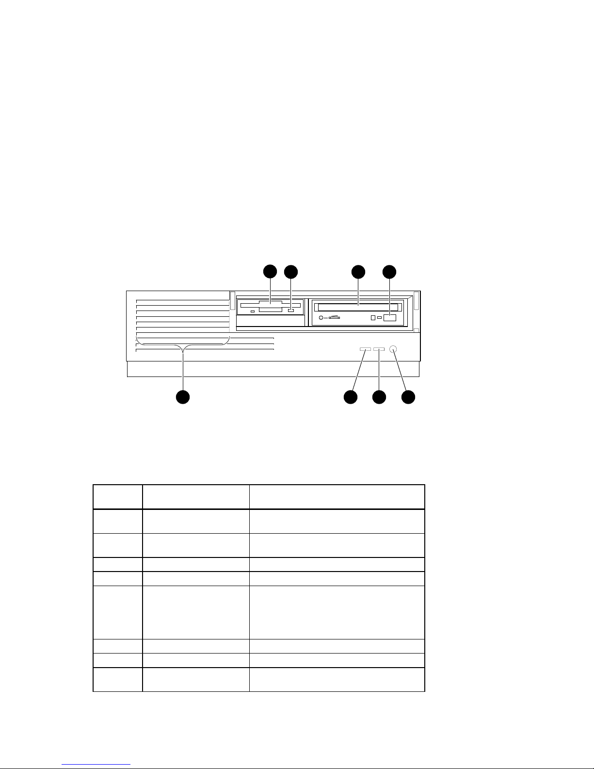
Figure 1-1 shows a front view of the system enclosure with pointers to the controls and
indicators (storage bay door removed for clarity). Table 1-1 describes these items.
System Overview
1
2
3
78
Figure 1-1 Front Controls, Indicators, and Drive Bay Locations
Table 1-1 Front Control, Indicators, and Drive Bay Locations
Figure
Legend
1 Floppy or tape drive bay Location of external bay for 3.5-inch floppy
2 Diskette eject button Releases a 3.5-inch diskette from the diskette
3 CD drive bay Location of 5.25-inch CD-ROM device.
4 CD-ROM eject button Opens the CD loading drawer
5 Halt/Reset button Jumper Selectable. When halt is pressed, the
6 LED Indicator DC On, lights when the system is on.
7 LED Indicator Lights to indicate SCSI activity.
8 Louvered air intake Passageway for cooling air to enter the
Control or Indicator Function
diskette or optional tape device.
drive.
system halts immediately (the halt button is a
momentary contact switch). When reset is
pressed, resets the system and causes the selftest to run.
system. (Do not block the air intake.)
6
4
5
MA00999
AlphaStation 500 Series User Information
1-3
System Overview
Enclosure Rear Panel
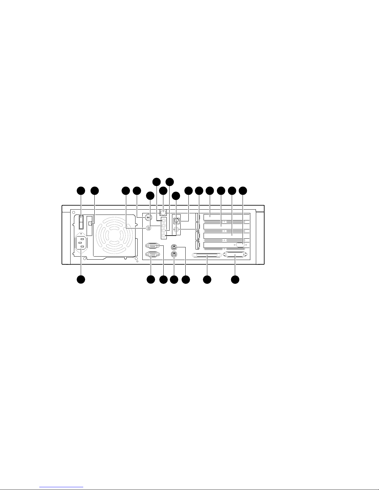
Figure 1-2 shows the rear controls and connectors. Table 1-2 lists the rear controls and
connectors and describes their functions.
2 3
1
6
8
4
7
5
10
9
11
12
13
14
15
22
18
21
1920
17
Figure 1-2 Rear Connectors (Rear View)
16
MA00995
1-4
AlphaStation 500 Series User Information

Table 1-2 Rear Connectors
System Overview
Figure
Legend
1 On/Off Switch Power
2 Voltage selection
3 Lock Slot Use with optional Kensington type security lock
4 System (chassis)
5 Sound card stereo
6 Sound card stereo
7 Top Cover Screw Secures top cover
8 Sound card
9 Sound card stereo
10 Twisted Pair
11 ThinWire connector Connection to the embedded Ethernet controller
12 64-bit PCI
13, 14, 15 32-bit PCI
16 Enhanced bi-
17 Wide SCSI
18 Keyboard connector Connects a VMS or PS/2 style keyboard
19 Mouse connector Connects a PS/2-compatible mouse
20 COM1 - Serial port
21 COM2 - Serial port
22 AC power connector Connects the system to AC power
Item Function
Allows user to set voltage from factory set 230V
switch
lock
LINE OUT
connector
headphone jack
microphone jack
LINE IN connector
connector
expansion slot
expansion slots
directional parallel
port
connector - 68-pin
connector
connector
to 115 VAC power
Provides security for internal components.
Routes audio signals to an external amplifier
Connects headphones, or amplified speakers
Connects microphone (2.2Ohm to 2.5V)
Brings audio signals into the card (for example,
from a stereo amplifier)
Connection to the embedded Ethernet controller
Used for PCI expansion options
In this example, a PCI graphics adapter is shown
in the bottom slot. It provides the interface
between the video/graphics expansion module
(option) and the supported monitor.
Connects an industry-standard parallel printer or
other parallel device
Provides the interface between the system unit
and external SCSI devices
Connects serial devices
Connects serial devices
AlphaStation 500 Series User Information
1-5
System Overview
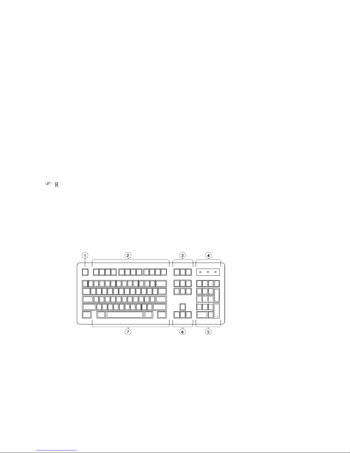
The Keyboard
Your system comes equipped with a 101-key enhanced keyboard (shown in) that allows
you to communicate with your system by entering data or commands. Note that some
European keyboards have 108 keys. Refer to Figure 1-3 and Table 1-3 for information on
keyboard key groups and functions.
Refer to your operating system or application software documentation for software-
)
specific key functions.
_________________________ NOTE____________________________
You can adjust the angle of the keyboard for your comfort. The underside of the
keyboard has feet that swing down and lock into place.
___________________________________________________________
Figure 1-3 Typical Keyboard Layout
1-6
AlphaStation 500 Series User Information

Table 1-3 Key Groups and Functions
System Overview
Figure
Legend
1 [Escape] key This key is program-specific. Its function is
2 Function key group These keys are program-specific. Their
3 Edit key group These keys are program-specific. Their
4 Indicator lights These lights indicate whether [NumLock],
5 Numeric keypad These keys perform numeric functions and
6 Cursor control key group These keys control the movement of the
7 Alpha-numeric key group These typewriter-specific keys feature
Key, Key Group Function
determined by the installed application
software.
functions are determined by the installed
application software.
functions are determined by the installed
application software.
[CapsLock], or [ScrollLock] has been
activated.
software-defined functions, including cursor
control. The [NumLock] key allows you to
toggle between the numeric functions and
software-defined functions.
highlighted cursor on the monitor screen.
automatic-repeat capability. If you press and
hold down any of these keys, the keystroke
repeats automatically until released.
AlphaStation 500 Series User Information
1-7


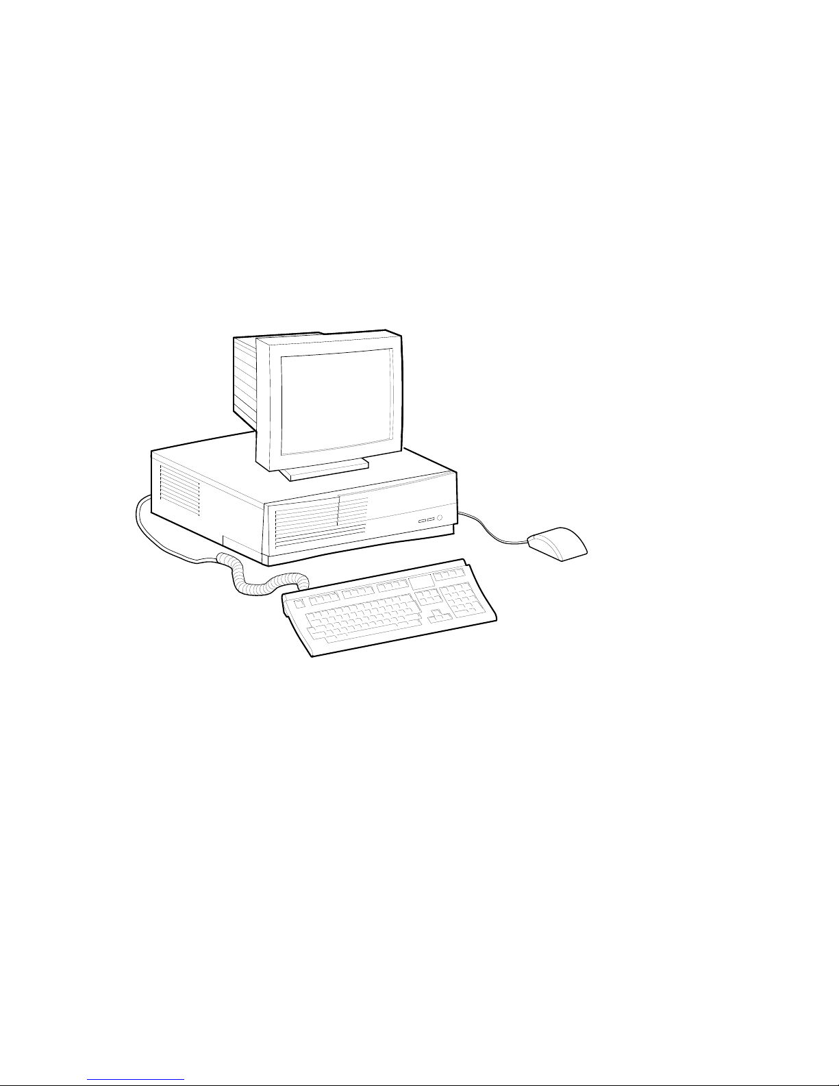
Introduction
This chapter describes how to install, start, restart, and turn off your AlphaStation 500
Series system. You can also find information here about preloaded software as well as
guidelines for system security. Figure 2-1 shows a typical AlphaStation 500 Series system.
________________________WARNING __________________________
When unpacking and moving system components, be aware that some
components (such as the system unit or monitor) may be too heavy for you
to safely lift alone. If you are doubtful about whether you can lift these items
alone, please get assistance.
____________________________________________________________
2
Getting Started
AlphaStation 500 Series User Information 2-1
Getting Started
MA01000
Figure 2-1 AlphaStation 500 Series System
Before Starting Your System
Before you start your system, follow this procedure:
1. Read and understand the information supplied with your system.
2. Select a well-ventilated site near a grounded power outlet and away from sources of
excessive heat. Also, use an appropriate power strip to isolate the site from electric
noise (for example, spikes, sags, and surges) produced by devices such as air
conditioners, large fans, radios, and televisions.
3. Save all shipping containers and packing material for repackaging or moving the
system later.
2-2
AlphaStation 500 Series User Information

_________________________ NOTES____________________________
• Do not install optional hardware or application software until you have
started your system and verified that the base system is working correctly.
• • On systems that have preloaded software, a label attached to the system unit
informs you that there is licensed software installed. Carefully review the
software license agreement shipped with your system.
____________________________________________________________
Identifying the Correct AC Power Cord
The proper AC power cord accompanies your AlphaStation 500 Series system. Because
variations exist from one country to another, and systems may be moved, inspect your
power cord to ensure that it is the correct one for your country or region. If you are not
sure that the supplied AC power cord is correct, contact your authorized Digital service
representative or distributor before you use it.
________________________WARNING __________________________
Do not attempt to modify or use an external 115V AC power cord for 230V
AC input power. Modifying the power cord can cause personal injury and
severe equipment damage.
____________________________________________________________
Getting Started
Power cords supplied with the Digital AlphaStation 500 Series system meet the following
criteria:
• The cords are UL-listed and CSA-certified, rated for use at 250V AC with a current
rating that is at least 125% of the current rating of the Digital AlphaStation 500 Series
system. In Europe, the cordage carries the <HAR> mark.
• The AC plug is terminated in a grounding-type male plug designed for use in the
region. It must also have marks showing certification by an agency acceptable in the
region.
• The connector at the computer end must be an IEC
• The cord length does not exceed 4.5 m (14.5 ft).
1
International Electrotechnical Commission.
2
International Commission for Conformity Certification of Electrical Equipment.
1
-type CEE2-22 female connector.
AlphaStation 500 Series User Information
2-3
Getting Started
Installing Your System
The AlphaStation 500 Series Installation Information you received with your system
graphically outlines the steps to follow to install your system.
1. Make sure you received all of your system components. Use Appendix H, Equipment
Log, to list your equipment. If something is missing, please contact your distributor or
Digital representative.
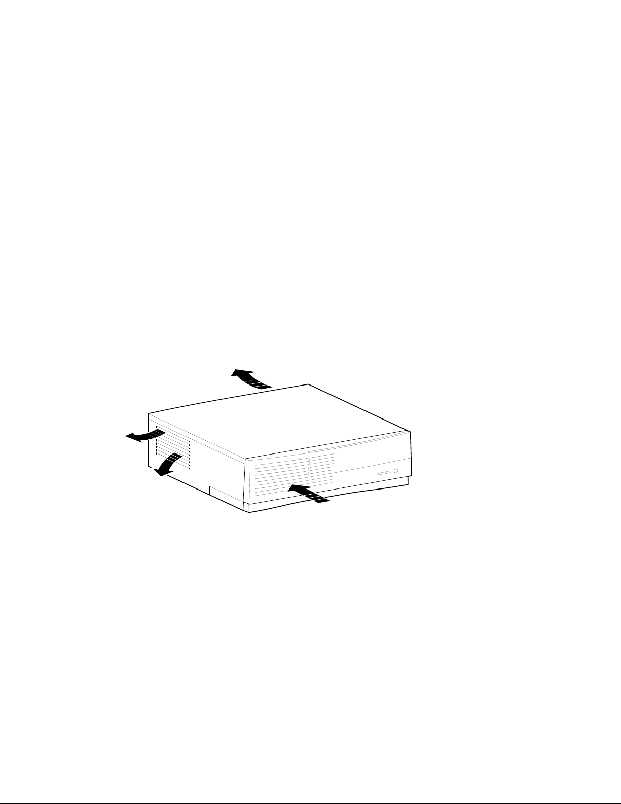
2. Position your system so that air can flow freely to and from the vents, as shown in
Figure 2-2.
Figure 2-2 System Enclosure Airflow
_______________________ CAUTIONS _________________________
To ensure that your system is properly cooled:
• Make sure that air can freely flow into the front, out of the side and rear of
the system unit.
• Do not remove a filler plate until you are ready to add a new system
component.
___________________________________________________________
2-4
AlphaStation 500 Series User Information
MA00975
 Loading...