

Page 1

AlphaServer 800
User’s Guide
Order Number: EK–ASV80–UG. B01
This manual is intended for the user of the DIGITAL AlphaServer
800 server system. It describes the operation of the system, explains
the use of the SRM and the AlphaBIOS consoles, gives procedures
for component replacements, and discusses troubleshooting.
Digital Equipment Corporation
Maynard, Massachusetts
Page 2

Second Printing, November 1997. Revised.
Digital Equipment Corporation makes no representations that the use of its products in the
manner described in this publication will not infringe on existing or future patent rights, nor
do the descriptions contained in this publication imply the granting of licenses to make, use, or
sell equipment or software in accordance with the description.
The information in this document is subject to change without notice and should not be
construed as a commitment by Digital Equipment Corporation. Digital Equipment Corporation
assumes no responsibility for any errors that may appear in this document.
The software, if any, described in this document is furnished under a license and may be used
or copied only in accordance with the terms of such license. No responsibility is assumed for
the use or reliability of software or equipment that is not supplied by Digital Equipment
Corporation or its affiliated companies.
Copyright 1997 by Digital Equipment Corporation. All rights reserved.
The following are trademarks of Digital Equipment Corporation: AlphaServer, OpenVMS,
StorageWorks, VAX, and the DIGITAL logo.
The following are third-party trademarks: Lifestyle 28.8 DATA/FAX Modem is a trademark
of Motorola, Inc. UNIX is a registered trademark in the U.S. and other countries, licensed
exclusively through X/Open Company Ltd. U.S. Robotics and Sportster are registered
trademarks of U.S. Robotics. Windows NT is a trademark of Microsoft, Inc. All other
trademarks and registered trademarks are the property of their respective holders.
FCC Notice: This equipment has been tested and found to comply with the limits for a Class
B digital device, pursuant to Part 15 of FCC rules. These limits are designed to provide
reasonable protection against harmful interference in a residential installation.
This equipment generates, uses, and can radiate radio frequency energy and, if not installed
and used in accordance with the instructions, may cause harmful interference to radio
communications. However, there is no guarantee that interference will not occur in a
particular installation. If this equipment does cause harmful interference to radio and
television reception, which can be determined by turning the equipment off and on, the user is
encouraged to try to correct the interference by one or more of the following measures:
• Reorient or relocate the receiving antenna
• Increase the separation between the equipment and receiver
• Connect the equipment into an outlet on a circuit different from that to which the receiver
is connected
• Consult the dealer or an experienced radio/TV technician for help
Page 3

This device complies with Part 15 of the FCC rules. Operation is subject to the following two
conditions: (1) this device may not cause harmful interference, and, (2) this device must
accept any interference received, including interference that may cause undesired operation.
Any changes or modifications made to this equipment may void the user’s authority to operate
this equipment.
If shielded cables have been supplied or specified, they must be used on the system in order to
maintain international regulatory compliance.
This Class B digital apparatus meets all the requirements of the Canadian InterferenceCausing Equipment Regulations.
Cet appareil numérique de la classe B respecte toutes les exigences du Réglement sur le
matériel broilleur du Canada.
——————————————————————————————————————
Page 4

Page 5

v
Contents
Preface............................................................................................................ xiii
Chapter 1 Overview
1.1 System Architecture .................................................................................1-2
1.2 System Features .......................................................................................1-4
1.3 System Parts.............................................................................................1-6
1.4 Control Panel ...........................................................................................1-8
1.5 Rear Panel Connections..........................................................................1-11
1.6 Storage Device LEDs .............................................................................1-13
1.7 Console..................................................................................................1-15
1.8 System Options ......................................................................................1-16
1.9 System Specifications.............................................................................1-18
1.10 Acoustical Data......................................................................................1-21
Chapter 2 Installing a System into a Cabinet
2.1 Shipment Box...........................................................................................2-2
2.2 Preparing the System................................................................................2-4
2.3 Marking the Installation Area in the Cabinet ............................................2-6
2.4 Preparing the Cabinet ...............................................................................2-8
2.5 Installing the System ..............................................................................2-10
2.6 Installing the Cable Management Bracket ..............................................2-12
2.7 Installing the Interlock Mechanism.........................................................2-14
2.8 Connecting the Cables............................................................................2-16
Page 6

vi
Chapter 3 Installing the System
3.1 System Setup Overview............................................................................3-1
3.2 Selecting a System Location.....................................................................3-1
3.2.1 Environmental Conditions .................................................................3-2
3.2.2 Power Requirements..........................................................................3-3
3.3 Identifying Accessories ............................................................................3-4
3.4 Connecting the System.............................................................................3-5
3.5 Connecting to Network Hardware ............................................................3-6
3.6 Locking Your System...............................................................................3-7
Chapter 4 Operating the System
4.1 Powering Up the System ..........................................................................4-2
4.4 Booting Windows NT.............................................................................4-10
4.5 Booting the Operating System for the First Time ....................................4-12
4.6 Powering Off the System........................................................................4-15
Chapter 5 Reconfiguring the System
5.1 AlphaBIOS Console Configuration Options .............................................5-2
5.2 SRM Console Configuration Commands ..................................................5-4
5.3 Memory Configuration.............................................................................5-8
5.4 Network Configuration.............................................................................5-9
5.5 EISA and ISA Options ...........................................................................5-11
5.6 EISA Configuration Utility (ECU) ......................................................... 5-13
5.7 Configuring EISA and ISA Options........................................................5-14
5.7.1 Running ECU..................................................................................5-15
5.7.2 Checking Required Environment Variable Settings ......................... 5-16
5.7.3 Verifying the System Configuration ................................................5-17
5.8 PCI Option Cards ...................................................................................5-18
5.9 Determining SCSI Storage Device IDs ................................................... 5-19
5.10 Updating Firmware ................................................................................5-21
5.10.1 Updating Firmware Using the CD-ROM Drive................................5-22
5.10.2 Updating Firmware Using the Network ...........................................5-23
5.10.3 Updating Firmware Using the Diskette Drive .................................. 5-23
Chapter 6 Using the SRM Console
6.1 Invoking the SRM Console.......................................................................6-1
6.2 SRM Console Tasks.................................................................................6-2
6.2.1 Displaying the System Configuration ................................................6-3
6.2.2 Booting the Operating System ...........................................................6-8
6.2.3 Testing the System ..........................................................................6-10
6.2.4 Forcing a System Crash Dump ........................................................ 6-12
Page 7

vii
6.2.5 Changing Environment Variables .................................................... 6-13
6.2.6 Depositing and Examining Data ...................................................... 6-16
6.2.7 Reading a File .................................................................................6-19
6.2.8 Initializing the System .....................................................................6-20
6.2.9 Finding Help ...................................................................................6-22
6.2.10 Switching from SRM to the AlphaBIOS Console.............................6-23
6.3 SRM Console Security Features .............................................................6-24
6.3.1 The Set Secure Command ...............................................................6-24
6.3.2 The Set Password Command ...........................................................6-24
6.3.3 The Login Command.......................................................................6-25
6.3.4 The Clear Password Command........................................................6-25
6.4 SRM Commands....................................................................................6-26
6.5 Environment Variables...........................................................................6-31
Chapter 7 Using the AlphaBIOS Console
7.1 Starting AlphaBIOS .................................................................................7-2
7.2 Keyboard Conventions and Help ..............................................................7-4
7.3 Displaying the System Configuration .......................................................7-6
7.3.1 System Board Configuration..............................................................7-8
7.3.2 Hard Disk Configuration .................................................................7-10
7.3.3 PCI Configuration ...........................................................................7-12
7.3.4 EISA Configuration.........................................................................7-15
7.3.5 SCSI Configuration .........................................................................7-16
7.3.6 Memory Configuration ....................................................................7-18
7.3.7 Integrated Peripherals......................................................................7-19
7.4 Updating Firmware ................................................................................7-20
7.5 Setting Up the Hard Disk........................................................................7-22
7.5.1 Manually Creating and Deleting Partitions ......................................7-26
7.5.2 Formatting a FAT Partition..............................................................7-28
7.6 Performing Setup Tasks.......................................................................... 7-30
7.7 Installing Windows NT ..........................................................................7-34
7.8 Running a Configuration Utility .............................................................7-36
7.9 Selecting the Version of Windows NT.................................................... 7-38
7.9.1 Designating a Primary Operating System.........................................7-40
7.9.2 Primary Operating System and the Auto Start Option ......................7-42
7.10 Switching from AlphaBIOS to the SRM Console ...................................7-46
7.11 Setting Up Password Protection..............................................................7-48
7.12 Running AlphaBIOS from a Serial Terminal ..........................................7-50
Chapter 8 Server Management
8.1 Operating the System Remotely ...............................................................8-2
8.2 RMC Functions........................................................................................8-3
8.3 First Time Setup.......................................................................................8-5
Page 8

viii
8.4 Resetting the RMC to Factory Defaults ....................................................8-9
8.5 Remote Management Console Commands..............................................8-10
8.6 RMC Troubleshooting Tips....................................................................8-21
Chapter 9 Using the Hard Disks
9.1 SCSI Bus Controller.................................................................................9-1
9.2 Configuration...........................................................................................9-1
9.3 External SCSI Expansion .........................................................................9-4
Chapter 10 Installing Components
10.1 Preparing to Install or Remove Components ...........................................10-2
10.2 Removing and Installing Memory DIMMs .............................................10-6
10.3 Removing and Installing Option Cards ................................................... 10-9
10.3.1 Installing and Removing an Option Card .......................................10-10
10.3.2 Testing an Option Card Installation ...............................................10-13
10.4 Installing Storage Devices ....................................................................10-15
10.4.1 Installing and Removing a Hard Drive...........................................10-16
10.4.2 Installing a 5.25-Inch Device .........................................................10-18
10.4.3 Installing SCSI Controller Options ................................................ 10-21
10.5 Removing/Replacing Other Options .....................................................10-26
Chapter 11 Troubleshooting
11.1 Troubleshooting Overview .....................................................................11-2
11.2 System Diagnostics ................................................................................11-4
11.2.1 Interpreting Error Beep Codes .........................................................11-4
11.2.2 Reading the Console Event Log....................................................... 11-6
11.2.3 The test Command .......................................................................... 11-6
11.2.4 The show_status Command .............................................................11-7
11.3 Power Problems .....................................................................................11-8
11.4 Console Problems...................................................................................11-9
11.5 Boot Problems......................................................................................11-10
11.6 Problems Detected by the Operating System ........................................11-12
11.7 Storage Problems .................................................................................11-13
11.8 Option Card Problems ..........................................................................11-15
11.9 Monitor and Terminal Problems ...........................................................11-18
11.10 Keyboard and Mouse Problems ............................................................ 11-20
11.11 Printer Problems...................................................................................11-22
11.12 Overheating Problems ..........................................................................11-22
11.13 Using the Fail-Safe Loader...................................................................11-23
11.14 Hard Disk Troubleshooting Suggestions...............................................11-25
Page 9

ix
Examples
4–1 DIGITAL UNIX and OpenVMS Power-Up Display.................................4-3
4–2 Booting DIGITAL UNIX from a Local Device ........................................4-6
4–3 Booting OpenVMS...................................................................................4-8
5–1 System Configuration Display..................................................................5-2
5–2 Show Config Command ...........................................................................5-4
5–3 Show Device Command ...........................................................................5-6
5–4 Show Memory Command.........................................................................5-6
5–5 Set and Show Commands .........................................................................5-7
5–6 Determining Device IDs.........................................................................5-20
6–1 Show Config Command ...........................................................................6-3
6–2 Show Device Command ...........................................................................6-4
6–3 Show Memory Command.........................................................................6-6
6–4 Show PAL Command...............................................................................6-7
6–5 Show Version Command..........................................................................6-7
6–6 Boot Command ........................................................................................6-8
6–7 Test Command.......................................................................................6-10
6–8 Crash Command.....................................................................................6-12
6–9 Set envar and Show envar Commands.................................................... 6-13
6–10 Edit Command .......................................................................................6-15
6–11 Deposit Command..................................................................................6-16
6–12 Examine Command................................................................................6-16
6–13 More Command .....................................................................................6-19
6–14 Initialize Command................................................................................6-20
6–15 Help (or Man) Command ......................................................................6-22
6–16 Switching to the AlphaBIOS Console.....................................................6-23
10-1 The show config Command Display .....................................................10-14
11–1 Test Command.......................................................................................11-7
Figures
1-1 Block Diagram of the AlphaServer 800 Server System .............................1-2
1-2 AlphaServer 800 System Parts..................................................................1-6
1-3 Control Panel ...........................................................................................1-8
1-4 Rear Panel Connections..........................................................................1-11
1-5 Hard Disk Drive LEDs ...........................................................................1-13
1-6 Floppy Drive Activity LED ....................................................................1-14
1-7 CD-ROM Drive Activity LED................................................................1-14
2-1 Unpacking the Rackmount System ...........................................................2-2
2-2 Preparing the System for Rackmount........................................................2-4
2-3 Rackmount Installation Area ....................................................................2-6
2-4 Preparing the Cabinet for Rackmount .......................................................2-8
2-5 Installing the System ..............................................................................2-10
Page 10

x
2-6 Installing the Cable Management Bracket ..............................................2-12
2-7 Installing the Interlock Mechanism.........................................................2-14
2-8 Cable Loop at the Rear of the System .....................................................2-16
3-1 System Dimensions and Service Area.......................................................3-2
3-2 Power Supply Requirements.....................................................................3-3
3-3 System Accessories..................................................................................3-4
3-4 System Connections .................................................................................3-5
3-5 Network Connections...............................................................................3-6
3-6 System Lock and Key...............................................................................3-7
4-1 Windows NT Power-Up Display ..............................................................4-2
4-2 AlphaBIOS Boot Screen.........................................................................4-10
5-1 Memory Banks.........................................................................................5-8
5-2 Network Connections...............................................................................5-9
5-3 EISA and ISA Cards...............................................................................5-11
5-4 EISA, ISA, and PCI Option Slots ...........................................................5-12
5-5 Run ECU from Floppy Dialog Box.........................................................5-15
5-6 PCI Option Card..................................................................................... 5-18
6-1 Device Naming Convention .....................................................................6-5
7–1 Boot Screen..............................................................................................7-2
7–2 AlphaBIOS Setup Screen .........................................................................7-3
7–3 Typical First-Level Help Screen ...............................................................7-4
7–4 Second-Level Help Screen .......................................................................7-5
7–5 Display System Configuration Screen ......................................................7-6
7–6 System Board Configuration ....................................................................7-8
7–7 Hard Disk Configuration ........................................................................ 7-10
7–8 PCI Configuration ..................................................................................7-12
7–9 Advanced PCI Information.....................................................................7-14
7–10 EISA Configuration................................................................................ 7-15
7–11 SCSI Configuration................................................................................7-16
7–12 Memory Configuration...........................................................................7-18
7–13 Integrated Peripherals............................................................................. 7-19
7–14 Updating Firmware ................................................................................7-20
7–15 Hard Disk Setup Screen..........................................................................7-22
7–16 Create New Partition Dialog Box ........................................................... 7-26
7–17 Delete Partition Dialog Box ...................................................................7-27
7–18 Formatting a FAT Partition .................................................................... 7-28
7–19 Standard Formatting...............................................................................7-29
7–20 Standard CMOS Setup Screen ................................................................7-30
7–21 Advanced CMOS Setup Screen ..............................................................7-32
7–22 Installing Windows NT ..........................................................................7-34
7–23 Run Maintenance Program Dialog Box ..................................................7-36
7-24 Execute Run Maintenance Program ........................................................7-37
7–25 Operating System Selections ..................................................................7-38
7–26 Primary Operating System......................................................................7-40
Page 11

xi
7–27 Operating System Selection Setup ..........................................................7-42
7–28 Switching to the SRM Console...............................................................7-46
7–29 Advanced CMOS Setup Menu................................................................7-48
8-1 Remote Management Console Block Diagram .........................................8-2
9-1 SCSI Drive IDs ........................................................................................9-2
9-2 RAID Cable for Hard Disk Drives............................................................9-3
10-1 Removing/Replacing Side Panel on a Pedestal .......................................10-2
10-2 Attaching the Antistatic Wrist Strap .......................................................10-4
10-3 Removing/Replacing Top Cover on a Rackmount ..................................10-5
10-4 Memory Connector Layout.....................................................................10-6
10-5 Removing a Memory DIMM..................................................................10-7
10-6 Installing a Memory DIMM ...................................................................10-8
10-7 PCI, EISA, and ISA Option Cards ........................................................10-10
10-8 Installing or Removing an Option Card ................................................10-11
10-9 SCSI Bus IDs.......................................................................................10-15
10-10 Installing a Hard Drive .........................................................................10-16
10-11 Installing a 5.25-Inch Device................................................................10-19
10-12 Continuing Installation of a 5.25-Inch Device ...................................... 10-20
10-13 RAID/SCSI Cable for Internal Disk Drive Backplane...........................10-22
10-14 Wide SCSI Cable for Breakouts at Rear of Enclosure ...........................10-23
10-15 Wide SCSI Dual Connector Cable for Std Bulkhead Connector ............ 10-24
11–1 J1 Jumper on the CPU Card (Normal Position) .....................................11-24
Tables
1 AlphaServer 800 Documentation...............................................................20
1-1 System Status Indicated by the Control Panel LEDs ...............................1-10
1-2 System Specifications.............................................................................1-18
1-3 AlphaServer 800 Acoustical Data...........................................................1-21
3–1 Environmental Conditions........................................................................3-2
3–2 System Accessories..................................................................................3-5
5–1 Resetting Environment Variables ........................................................... 5-16
5–2 Hard Drive SCSI ID Numbers ................................................................5-19
5–3 Determining Available SCSI IDs (SRM Console)...................................5-20
6–1 Summary of SRM Console Commands...................................................6-26
6–2 Notation Formats for SRM Console Commands .....................................6-28
6–3 Special Characters for SRM Console......................................................6-29
6–4 Environment Variable Summary ............................................................6-31
6–5 Settings for boot_osflags Bootflags (OpenVMS) ....................................6-35
7-1 Serial Terminal Key Commands for AlphaBIOS and ECU .....................7-50
8-1 Dial and Alert String Elements .................................................................8-6
8-2 RMC Troubleshooting............................................................................8-21
10–1 Testing with the show config Display ...................................................10-13
11–1 Determining Where to Look ...................................................................11-3
Page 12

xii
11–2 Error Beep Codes ...................................................................................11-5
11–3 Troubleshooting Power Problems ...........................................................11-8
11–4 Troubleshooting Console Problems ........................................................11-9
11–5 Troubleshooting Boot Problems ........................................................... 11-10
11–6 Problems Detected by the Operating System ........................................ 11-12
11–7 Troubleshooting Mass Storage Problems .............................................. 11-13
11–8 Troubleshooting EISA/ISA Bus Problems ............................................11-16
11–9 Troubleshooting PCI Bus Problems......................................................11-17
11–10 Troubleshooting Monitor and Terminal Problems ................................. 11-18
11–11 Troubleshooting Keyboard and Mouse Problems ..................................11-20
11–12 Troubleshooting the Hard Disk .............................................................11-25
Page 13

Preface
Intended Audience
This manual is intended for the operator of the AlphaServer 800 system.
Document Structure
This manual uses a structured documentation design. Topics are organized into small
sections for efficient online and printed reference. Each topic begins with an
abstract. You can quickly gain a comprehensive overview by reading only the
abstracts. Next is an illustration or example, which also provides quick reference.
Last in the structure are descriptive text and syntax definitions.
The material is presented in 11 chapters.
• Chapter 1, Overview, describes the features and the major parts of the system.
• Chapter 2, Installing a System into a Cabinet, explains how to install a unit
in a system cabinet.
• Chapter 3, Installing the System, explains how to set up and interconnect the
hardware components of the system.
• Chapter 4, Operating the System, tells how to power the system on and off,
discusses booting of the three operating systems, and operating the system
remotely.
• Chapter 5, Reconfiguring the System, tells how to use console commands to
reconfigure the system and describes how to run configuration utilities.
• Chapter 6, Using the SRM Console, tells how to invoke the SRM console and
describes how to perform certain SRM console tasks.
• Chapter 7, Using the AlphaBIOS Console, tells how to start AlphaBIOS and
perform common system management tasks.
• Chapter 8, Server Management Console, describes the integrated server
management console and explains how to operate the system remotely.
xiii
Page 14

• Chapter 9, Using the Hard Disks, describes the operation of the hard disks.
• Chapter 10, Installing Components, discusses how to remove and install
system components and add new options.
• Chapter 11, Troubleshooting, provides basic troubleshooting information for
the system.
Documentation Titles
Table 1 lists the books in the AlphaServer 800 documentation set.
Table 1 AlphaServer 800 Documentation
Title Order Number
AlphaServer 800 System Info Kit QZ–00XAA–GW
AlphaServer 800 User’s Guide EK–ASV80–UG
AlphaServer 800 Basic Installation EK–ASV80–IG
AlphaServer 800 Local Language Doc CD AG–R5DUA–BE
AlphaServer 800 System Maintenance Kit QZ–00XAB –GZ
AlphaServer 800 Service Guide EK–ASV80–SG
AlphaServer 800 Service Information (help file) AK–R2MAA–CA
AlphaServer 800 Illustrated Parts Breakdown EK–ASV80–IP
xiv
Page 15

Chapter 1
Overview
The AlphaServer 800 system is a high-performance, uniprocessor system intended
for use as a local area network (LAN) server or commercial applications server.
Ideal uses for the AlphaServer 800 system include the following:
• Application server−To run applications such as relational databases, electronic
mail, and communications
• Print server−To provide printing resources to PCs and other systems in a LAN
• File server−To provide disk storage to PCs and other systems in a LAN
• Compute server−To enable PCs to remotely run computation-intensive
applications
• Replicated site server−To operate in commercial applications due to remote
management features
This chapter provides an overview of the system. Sections are:
• System Architecture
• System Features
• System Parts
• Control Panel
• Rear Panel Connections
• Storage Device LEDs
• Console
• System Options
• System Specifications
• Acoustical Data
Overview 1-1
Page 16
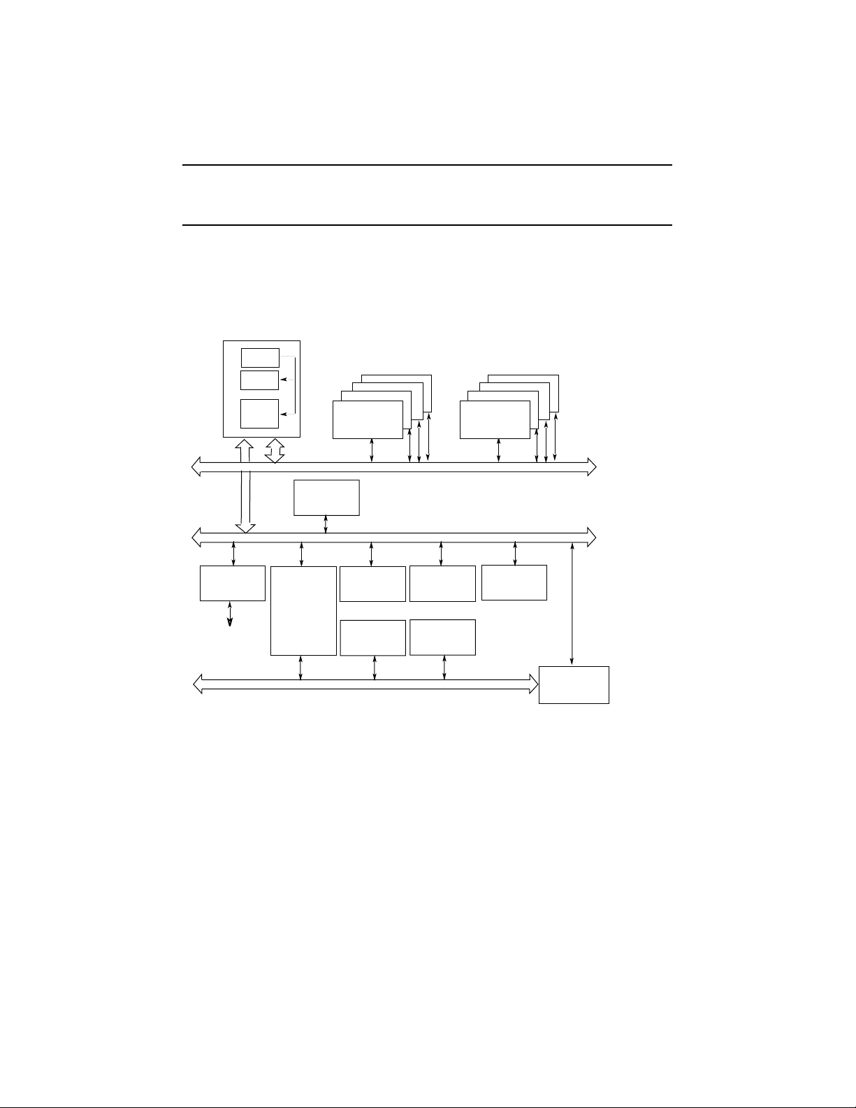
1.1 System Architecture
The AlphaServer 800 system is a low-end server that offers PCI and EISA bus
options on a single system board. Figure 1-1 shows the architecture of the
system.
Figure 1-1 Block Diagram of the AlphaServer 800 Server System
CPU
Cache
Xbar
Switch
SCSI
SCSI Bus
64-Bit
PCI
or
VGA
EISA Bus
Memory
Memory Bus
PCI Bus
32-Bit
PCI
32-Bit
PCI
EISAEISAEISA
Memory
32-Bit
PCI
PCI/EISA
Bridge
PK-0700E-97
1-2 AlphaServer 800 User’s Guide
Page 17

The AlphaServer 800 system is housed in an enclosure containing the motherboard,
CPU daughter card, other logic modules, and power supply with internal fans. The
enclosure allows for up to four internal mass-storage devices, with up to four
removable media devices, one of which is a 3.5-inch floppy drive. The control panel
includes Halt, Reset, and On/Off buttons. The system can be used as a deskside
pedestal in the vertical position, or, with the addition of brackets, may be mounted in
the horizontal position in a standard 19-inch rack.
All memory and I/O components are on a single system board that contains the
memory subsystem, the PCI bus, the EISA I/O bus, the integrated system I/O
controllers, and option slots for PCI-based and EISA-based option cards. A server
management corner on the system board serves to monitor/control the system
remotely.
The CPU daughter card interfaces to the motherboard with a 600-pin connector.
It is based on a 21164 microprocessor that is a superscalar, super-pipelined
implementation of the Alpha architecture and runs at an optimized price/
performance speed of 300 to 500 MHz. The chip contains two 8-Kbyte, directmapped primary caches and a 96-Kbyte, 3-way set-associative secondary cache. The
CPU card uses a 2-Mbyte, direct-mapped, writeback B-cache. The B-cache is 16
bytes wide with a block size of 64 bytes.
Overview 1-3
Page 18

1.2 System Features
The system offers a number of features that ensure high performance,
expandability, enhanced reliability, high availability, remote server
management, and improved security.
High Performance
• 64-bit Alpha architecture
• Microprocessor
• 2-Mbyte third-level cache
• Integrated fast wide SCSI controller
• Integrated PCI graphics
controller
• Warm-swapping of 3.5-inch full-
height devices
• Ultra SCSI-ready backplane
Operating Systems DIGITAL UNIX
Flexible Packaging Single enclosure available as free-
System Expansion
Provides significantly better performance
than 32-bit architecture.
Fast microprocessor for enhanced system
performance.
Reduces significantly memory
transaction times.
Supports tape, CD-ROM, and hard disk
devices without use of an expansion slot.
Makes an additional expansion slot
available for other applications.
Allows replacement of disk drives while
the system continues to operate.
Provides high-performance drive
technology.
OpenVMS
Windows NT
standing pedestal or rack-mountable box.
• Flexible memory architecture Provides a 256-bit memory data path.
Allows incremental memory expansion
from 32 Mbytes to 2 Gbytes.
1-4 AlphaServer 800 User’s Guide
Page 19

• Three 32-bit PCI slots, one shared
64-bit PCI/EISA slot, and two
dedicated EISA slots
Accommodates industry-standard option
cards such as Ethernet, FDDI, SCSI, and
modems.
• Capacity for eight internal storage
devices
• External ports
Reliability/Availability
• Error correction code (ECC)
• Internal sensors
• Variable fan speed
Server Management
• System diagnostics
A modular storage system accommodates up to four 3.5-inch full-height
SCSI devices. The system also supports
up to three 5.25-inch half-height devices
(CD-ROM or tape) and one 3.5-inch
high-density diskette drive.
Two serial ports and one parallel port
support external options such as printer,
modem, or local terminal.
Allows recovery from most cache and
memory errors.
Monitor and detect internal system
temperature, fan failure, power supply,
status, system watchdog timer.
Adjusts fan speed according to system
temperature.
Allows local and remote diagnosis of
system failures.
• Hardware configuration
• Firmware utility
• Remote management console
System Security
• Key lock (pedestal only) Limits access to system components.
• Security hole (on rear of system
unit)
Allows local and remote system
configuration.
Enables loading and verification of latest
firmware versions.
Enables monitoring of system conditions
and manipulating of the control panel
from a remote terminal. Provides
operator paging on “alert” conditions.
Allows system to be secured in place.
Overview 1-5
Page 20

1.3 System Parts
Figure 1-2 identifies the main parts of the system in a pedestal version. The
enclosure has a top cover and a side panel.
Figure 1-2 AlphaServer 800 System Parts
9
7
2
3
5
4
8
6
1
IP00110B
1-6 AlphaServer 800 User’s Guide
Page 21

The main components of an AlphaServer 800 system are:
²
Removable side cover of system enclosure
³
Floppy diskette drive
´
Removable media drives
µ
Lower and upper doors
Control panel
·
Hard disk drives
¸
System board
¹
CPU daughter card
º
Power supply
Overview 1-7
Page 22

1.4 Control Panel
The control panel provides system controls and status indicators on the front of
the AlphaServer 800 enclosure.
Figure 1-3 Control Panel
1
2
34
1-8 AlphaServer 800 User’s Guide
IP00039-97
Page 23

The control panel consists of three pushbutton controls and two LED indicators:
• Power On/Off button
• Halt button
• Reset button
• Green Power OK indicator
• Amber Halt indicator
The functions provided by these pushbutton conrols and indicators are discussed
next.
²
Power On/Off — Powers the system on or off. When the LED is lit, the
power is on. Turning the power off and then on clears the shutdown condition
and attempts to power the system back on. Failure conditions that prevent
the system from powering on can be determined from the remote
management console using the Status command. The remote management
console is powered separately from the rest of the system and is functional as
long as AC power is present.
The Power On/Off button overrides the remote management console. Thus, a
system that has been powered off or halted remotely can be restarted from the
control panel without the need to access the remote management console.
This becomes important in systems without a local character cell terminal for
a system console where no local access to the remote management console is
possible.
³
Halt button — When the button is in the In position, a single halt interrupt is
provided to the CPU. On OpenVMS and DIGITAL UNIX this halt interrupt
causes a return to the SRM console. Also, when the Halt button is In at
power-up, the system comes up with the SRM console.
´
Reset button — A momentary contact switch that initializes the system.
µ
Indicator lights — The control panel has two lights for indicating the basic
system state. One is a green Power OK indicator and the other is an amber
Halt indicator. The system state is described in Table 1-1.
Overview 1-9
Page 24

Table 1-1 System Status Indicated by the Control Panel LEDs
Green LED Yellow LED Status
Off Off System is powered off or no AC
power is present.
Off On Power is enabled, but system has
been powered off by:
• Remote console command
• System software
• Fan failure
• Overtemperature failure
• Power supply failure
On Off System is powered on.
On On System power is on and Halt button is
pressed in or a halt in command has
been issued at the remote
management console.
1-10 AlphaServer 800 User’s Guide
Page 25
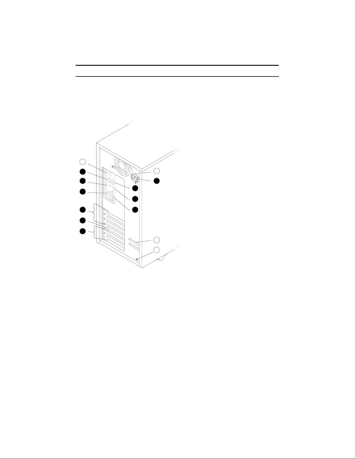
1.5 Rear Panel Connections
Rear panel ports and slots are shown in Figure 1-4.
Figure 1-4 Rear Panel Connections
1
5
6
7
9
8
2
10
1
2
3
4
3
4
IP00030A-97
Overview 1-11
Page 26

The following list describes the rear panel connections:
²
Three 32-bit PCI slots — For option cards for high-performance network, video,
or disk controllers
³
One 64-bit slot — For either a PCI card or an EISA card
´
Two EISA slots — For option cards for network, video, sound, or disk
controllers
µ
Parallel port — To parallel device such as a printer
Serial port (COM2) — Extra port to modem or any serial device
·
Mouse port — To PS/2-compatible mouse
¸
VGA port — To VGA monitor
¹
Keyboard port — To PS/2-compatible keyboard
º
Remote console modem port — Dedicated 9-pin port for connection to remote
management console and system COM1 through modem. Provides full
modem control.
»
Power inlet — To power outlet
¨
Serial port/terminal port (COM1) — To console terminal. This is an M MJ
with data leads only.
©
AC switch 115V/220VKey — Should be pointing to the correct input AC
voltage.
ª
SCSI breakouts — To SCSI devices
«
Security hole — To secure the system
1-12 AlphaServer 800 User’s Guide
Page 27
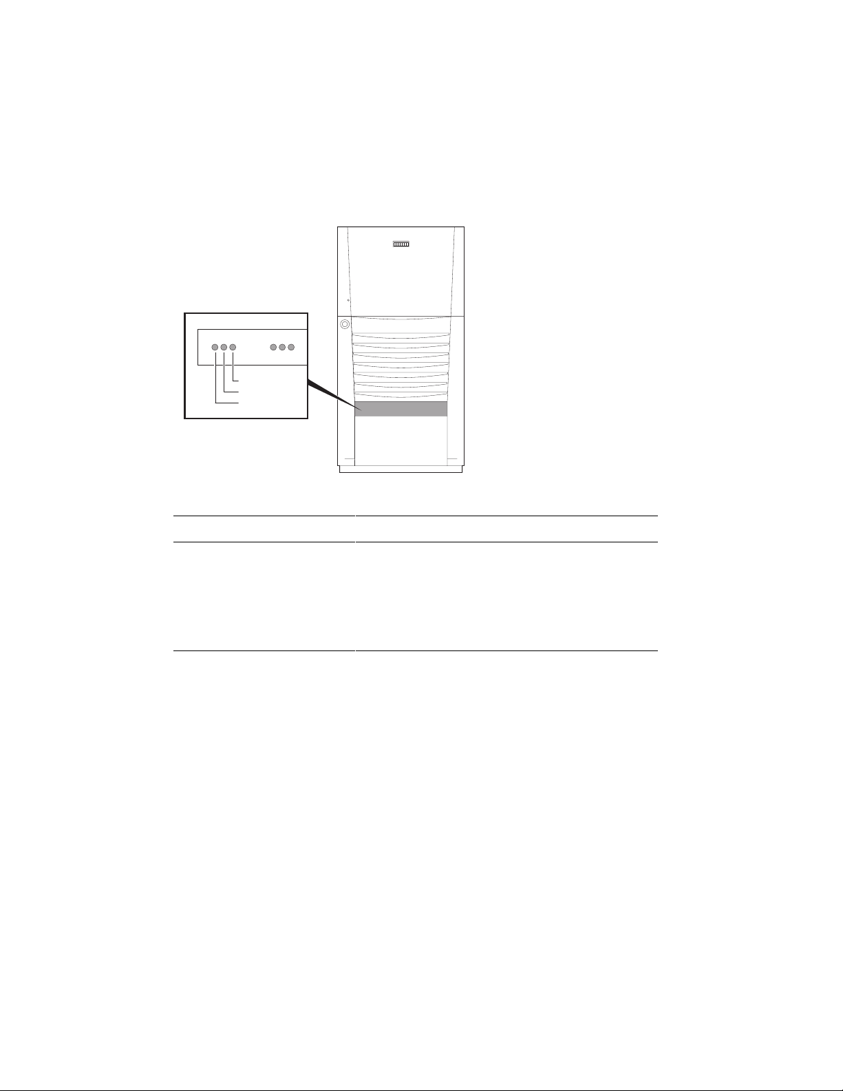
1.6 Storage Device LEDs
Storage device LEDs indicate the status of the device. Figure 1-5 shows the hard
disk drive LEDs.
Figure 1-5 Hard Disk Drive LEDs
DiskPresent
Fault
Activity
IP00080
LED Function
Activity (green) When lit indicates disk activity.
Fault (amber) Reserved for future use. Has no function at
product introduction.
Disk Present (green) When lit, indicates that a drive is installed in that
slot.
Overview 1-13
Page 28
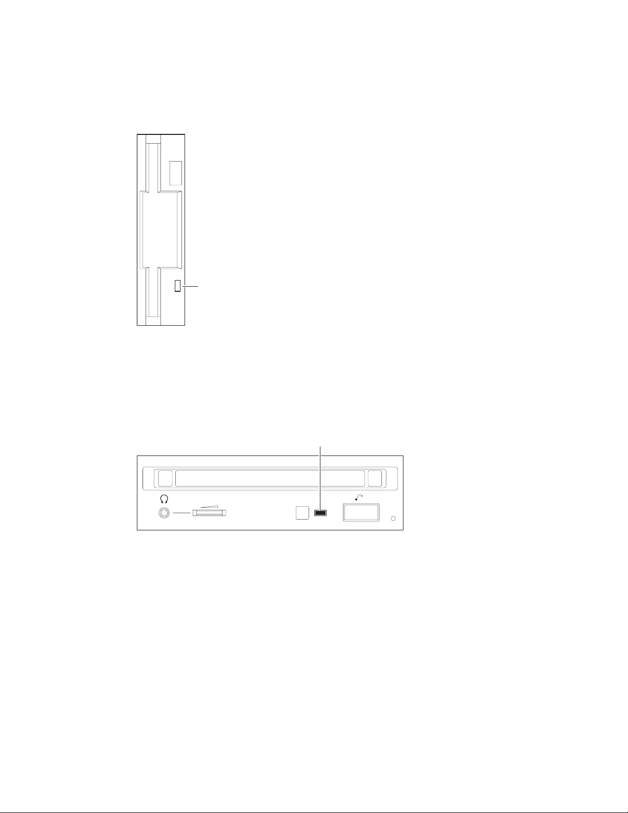
Figure 1-6 shows the Activity LED of the floppy drive. When lit, it indicates that
the drive is active.
Figure 1-6 Floppy Drive Activity LED
Activity LED
IP00081-97
Figure 1-7 shows the Activity LED of the CD-ROM drive. When lit, it indicates that
the drive is active.
Figure 1-7 CD-ROM Drive Activity LED
Activity LED
1-14 AlphaServer 800 User’s Guide
IP00082-97
Page 29

1.7 Console
The system offers two separate interfaces to the console program: SRM for
DIGITAL UNIX and OpenVMS; and AlphaBIOS for Windows NT.
The system runs in one of three modes:
• Operating system mode
• Console mode
• Remote management mode
In operating system mode, the system is under the control of the operating system.
When the operating system is halted, the system reverts to console mode. In this
mode, the system operates under the control of the console firmware and the
commands entered or selected by the operator.
The console firmware is located in a flash ROM (read-only memory) on the system
board. It boots the operating system, runs configuration utilities, displays the
system configuration, and runs diagnostic tests.
Remote management mode can be entered through an escape sequence at the local
terminal or modem port. This allows remote access to the control panel functions. It
also allows maintenance of system environmental conditions and the setup of alerts
for changes in certain operating conditions.
Because the AlphaServer 800 system supports multiple operating systems, it offers
two separate interfaces to the console program:
• SRM—For the OpenVMS and DIGITAL UNIX operating systems
• AlphaBIOS—For the Windows NT operating system
The SRM console firmware has a command-line interface. The operator enters
commands at the console prompt. Environment variables are used to control system
behavior.
The AlphaBIOS console firmware has a menu-based interface. The operator selects
an item from the menu displayed on a screen.
Refer to Chapter 6 for the operations of the SRM console and to Chapter 7 for the
operations of the AlphaBIOS console.
Overview 1-15
Page 30

1.8 System Options
The AlphaServer 800 system supports storage options, PCI/EISA/ISA options,
and memory options.
Internal Options
The AlphaServer 800 system supports the following types of internal options:
• Storage
• PCI/EISA/ISA
• Memory
Storage devices include:
• One diskette drive
• Up to three removable-media storage devices, one of which is typically a CD-
ROM drive
• Up to four 3.5-inch full-height SCSI hard disks
The system supports PCI/EISA/ISA options, including those for:
• SCSI storage expansion
• Networking and communication
• Graphics
The memory cards are inserted on eight 168-pin, 3.3 volt DIMM sockets on the
system board. Memory is configured in banksets of four to form the databus width
of 256 data bits and 32 bits of ECC. Possible memory capacities range from 32
Mbytes (using a single bankset of 1Mx72 DIMMs) to 2 Gbytes (using 32Mx72
DIMMs). Each DIMM in a bankset must be of the same capacity. Each bankset is
separately configurable as to base address and size.
1-16 AlphaServer 800 User’s Guide
Page 31

External Options
Other options that can be added to the system externally include the following:
• Monitor or terminal
• Expansion boxes
• Printers
• RAID controller
• Uninterruptible power supply (UPS)
• Modem
Ordering Options
The list of supported options is subject to change. Contact your sales representative
for information on the current list of supported options and for information on
ordering. If you are an Internet participant, you can obtain information related to the
AlphaServer 800 system through the DIGITAL FTP archive:
ftp://ftp.digital.com/pub/Digital/Alpha/systems/as800/
The WWW site for technical documentation and supply lists is:
http://www.digital.com/alphaserver/tech_docs/alphasrv800/
Users of the Windows NT operating system can access the Microsoft hardware
compatibility list (HCL) of officially supported devices through:
http://www.windowsnt.digital.com/support/hcl/hcl.htm
Overview 1-17
Page 32

1.9 System Specifications
Table 1-2 gives the AlphaServer 800 system specifications.
Table 1-2 System Specifications
Physical Characteristics
Pedestal
Height
Width
Depth
Weight
Rackmount
Height
Width
Depth
Weight
1. When lifting
2. Total added to cabinet
(includes brackets,
slides, and cables)
Shipping Container
(Pedestal and
Rackmount)
Height
Width
Depth
Weight
Pedestal
Rackmount
45 cm (17.7 in.)
22.6 cm (8.9 in.)
65.8 cm (25.9 in.)
Typical: 24.5 kg (54 lb)
22 cm (8.6 in.)
Standard EIA 310D
(RETMA)
63.8 cm (25.1 in.)
Typical: 24.5 kg (54 lb)
Typical: 30 kg (66 lb)
47 cm (18.5 in.)
60 cm (23.6 in.)
77.5 cm (30.5 in.)
Typical: 33 kg (73 lb)
Typical: 39 kg (85 lb)
Max: 28 kg (62 lb)
Fits 8 ¾ in. [5U] standard
EIA 310D (RETMA)
cabinets
Max: 28 kg (62 lb)
Max: 35 kg (77 lb)
Max: 37 kg (82 lb)
Max: 44 kg (96 lb)
Max Heat Dissipation 380 Watts, 1297 Btu/hr
Acoustics Operating LNPEc (BELs) 6.0 max
per ISO 7779
1-18 AlphaServer 800 User’s Guide
Page 33

Table 1-2 System Specifications (Continued)
Clearances
Operating
Pedestal
Front
Rear
Left side
Right side
Rackmount
Environmental Characteristics
75 cm (29.5 in.)
15 cm (5.9 in.)
None
None
See requirements of
specific cabinet
Service
75 cm (29.5 in.)
75 cm (29.5 in.)
75 cm (29.5 in.)
5 cm (2 in.)
Slides forward 68.6 cm (27
in.), then accessible from
the top
Temperature Operating
Pedestal
Rackmount
Nonoperating
Storage (60 days)
Rate of change
Relative Humidity Operating
Nonoperating
Storage (60 days)
Rate of change
Max Wet Bulb Temp Operating
Storage (60 days)
Min Dew Point Temp Operating
Storage (60 days)
Airflow and Quality Intake location
Exhaust location
Particle size
Concentration
Altitude Operating
Nonoperating
10 to 40
10 to 35
Not tested
-40 to 66
11
20 to 80%
20 to 80%
10 to 95%
20%/hr
28
46
2
Not tested
Front
Rear
N/A
N/A
3037 m (10,000 ft)
12190 m (40,000 ft)
o
C (50 to 104o F)
o
C (50 to 95o F)
o
C (-40 to 151o F)
o
C/hr (20o F/hr
o
C (82o F)
o
C (115o F)
o
C (360o F)
Vibration Operating 10-500 Hz .1 G peak
Overview 1-19
Page 34

Table 1-2 System Specifications (Continued)
Electrical Characteristics
Nominal AC Voltage
Voltage Range (Vac temporary condition)
Power Supply Phase
Nominal Frequency
Frequency Range
RMS Current (steady state) at Nominal Voltage
Max Power Consumption
100 to 120 Vac/220 to 240 Vac
88 to 132 Vac/176 to 264 Vac
Single/Single
60 Hz/50 Hz
57-63 Hz/47-53 Hz
7.0 amps/3.0 amps
380 Watts
1-20 AlphaServer 800 User’s Guide
Page 35

1.10 Acoustical Data
Table 1-3 gives the noise declaration for an AlphaServer 800 system with diskless,
1-Gbyte or 2-Gbyte RZ28M configurations.
Table 1-3 AlphaServer 800 Acoustical Data
Acoustics — Declared Values per ISO 9296 and ISO 7779
Sound Power Level
L
wAd
, B
Sound Pressure Level
L
pAm
, dBA
(bystander positions)
Product Idle Operate Idle Operate
PB80A-A9 (AlphaServer 800)
5.7
5.7
39
39
[with 0 x HDD]
PB80A-A9 + RZ26N
PB80A-A9 + RZ28M
Current values for specific configurations are available from DIGITAL representatives. 1 B = 10 dBA.
5.7
5.7
6.0
6.0
39
39
42
42
Schallemissionswerte — Werteangaben nach ISO 9296 und ISO 7779/DIN
EN27779
Schalleistungspegel
, B
L
wAd
Schalldruckpegel
L
, dBA
pAm
(Zuschauerpositionen)
Gerät Leerlauf Betrieb Leerlauf Betrieb
PB80A-A9 (AlphaServer 800)
5.7
5.7
39
39
[mit 0 x HDD]
PB80A-A9 + RZ26N
PB80A-A9 + RZ28M
Aktuelle Werte für speziele Ausrüstungsstufen sind uber die Digital Equipment Vertretungen erhältelich.
1 B = 10 dBA.
5.7
5.7
6.0
6.0
39
39
42
42
Overview 1-21
Page 36

Page 37

Chapter 2
Installing a System into a Cabinet
This chapter gives installation procedures for a rackmount system. Sections are:
• Shipment Box
• Preparing the System
• Marking the Installation Area in the Cabinet
• Preparing the Cabinet
• Installing the System
• Installing the Cable Management Bracket
• Installing the Interlock Mechanism
• Connecting the Cables
CAUTION: Because of heavy lifting and maneuvering involved, two people are
needed to handle the installation. A single person should NOT attempt to install the
system.
Installing a System into a Cabinet 2-1
Page 38

2.1 Shipment Box
The rackmount system is shipped in a single box. Figure 2-1 shows the hardware
shipped with the system.
Figure 2-1 Unpacking the Rackmount System
2-2 AlphaServer 800 User’s Guide
IP00058
Page 39

The rackmount system is shipped in a single box that contains the following items:
• The AlphaServer 800 system already assembled
• Front bezel assembly—P/N 70-33178-01
• Poly bag containing mounting hardware
The mounting hardware consists of the following items:
Mounting Hardware Part Number
Four slide brackets 74-51454-01
Two front mounting brackets 74-51572-01
One actuator trip bracket 74-51571-01
Four nut bars 74-51531-01
Six M4 x 6 mm pan head screws N/A
Eleven M4 x 10 mm pan head screws 90-40005-06
Sixteen 10-32 X 0.5 truss head screws 90-00063-39
Six 10-32 U-nuts 90-07786-00
Four M4 kepnuts 90-40203-02
In addition, the shipping box includes the following items to be secured to the
cabinet or mounted on the system:
• One front bezel
• Two chassis slides
• One cable management bracket
• One actuator stabilizer bracket
• One actuator latch
You need to do preinstallation work to prepare the system for mounting into the
cabinet.
Installing a System into a Cabinet 2-3
Page 40

2.2 Preparing the System
Prepare the system as described in the following procedure. Use Figure 2-2 as a
guide.
Figure 2-2 Preparing the System for Rackmount
2
3
1
IP00055B-97
2-4 AlphaServer 800 User’s Guide
Page 41

Prepare the system as follows:
CAUTION: The chassis slides are lightly greased. Handle them carefully to avoid
soiling of clothing.
²
1. Attach a front mounting bracket
mm screws per bracket.
to each side of the system using two M4 x 10
2. Tighten an M4 x 10 mm screw at the back end of the right side of the system.
3. Pull the narrow segment ´ of the chassis slide out of a chassis slide and detach
µ
it completely by pressing down the retainer spring
Position the chassis slide track so that the end of the chassis slide with three
holes
system with three M4 x 6 mm screws.
Repeat the step for the other chassis slide.
The system is now ready for installation.
will stick out past the system. Secure the chassis slide track to the
·
and continuing to pull.
³
Installing a System into a Cabinet 2-5
Page 42

2.3 Marking the Installation Area in the Cabinet
Determine the installation area as shown in Figure 2-3.
Figure 2-3 Rackmount Installation Area
NEMA
0.500 inch
0.625 inch
0.625 inch
0.500 inch
Metric
25 mm
25 mm
4.375 inch
4.375 inch
2-6 AlphaServer 800 User’s Guide
IP00064
Page 43

The installation of the rackmount system requires 8.75 inches (5U) of vertical height
in the cabinet.
1. Mark the midpoint hole on the vertical rail as shown in Figure 2-3. The midpoint
hole must be selected so that the holes immediately above and immediately
below are equidistant (.625 inches).
2. Mark the corresponding hole on the other three rails.
Installing a System into a Cabinet 2-7
Page 44

2.4 Preparing the Cabinet
Prepare the cabinet as described in the following procedure. Use Figure 2-4 as a
guide.
Figure 2-4 Preparing the Cabinet for Rackmount
3
5
8
6
4
2
1
7
2-8 AlphaServer 800 User’s Guide
9
IP00062B
Page 45

Prepare the cabinet as follows:
1. Attach slide brackets to the cabinet rails.
²
Attach slide bracket
two 10-32 screws and one nut bar
behind the vertical rail of the cabinet and the nut bar installs behind the slide
bracket, as shown in Figure 2-4.
NOTE: The chassis slide bracket has two dissimilar ends. Flip the bracket
and use the other end for larger hole spacing of 25 mm.
Locate the middle hole of the slide bracket and nut bar to the midpoint hole
marked on the vertical rail of the cabinet in Section 2.3. Tighten 10-32 screws
in the hole above and below the marked midpoint hole, leaving the midpoint
hole empty.
Attach the other three brackets to the rails in the same manner.
2. Attach chassis slides to the slide brackets.
Place the chassis slide into two brackets. Pull the inner slide out until the
forwardmost hole in the stationary segment of the chassis slide is exposed.
Aligns this hole with the forwardmost hole in the chassis slide bracket
that this happens when the stationary segment, the front of the slide bracket, and
the mounting surface of the vertical rail are vertically aligned. Fasten one M4 x
10 mm screw
hole in the stationary segment of the chassis slide and the slot in the rear
mounted slide bracket, and attach with a kepnut.
¸
to each of the four vertical rails of the cabinet ³ using
´
per slide bracket. The slide bracket installs
µ
·
and kepnut ¹. Place another M4 x 10 mm screw º through a
. Note
3. Repeat the procedure for the other slide
The cabinet is now ready for the installation of the system.
Installing a System into a Cabinet 2-9
Page 46

2.5 Installing the System
Install the system as described in the following procedure. Use Figure 2-5 as a
guide.
Figure 2-5 Installing the System
1
2
3
IP00065C-97
2-10 AlphaServer 800 User’s Guide
Page 47

Observe the following precautions before you begin to install the system into the
cabinet:
CAUTION:
1. Make sure that all devices are pushed into the cabinet and no device is
disengaged.
2. Activate the stabilizer foot of the cabinet, if the cabinet is so equipped, or
provide other means to stabilize the cabinet before installation of the system.
3. The system is heavy. It should be lifted by two persons.
1. Lift the system, align the narrow segment of the chassis slides attached to the
²
system with the chassis slides attached to the cabinet
the cabinet. Depress the retainer spring on both slides to slide the system
completely into the cabinet. Tighten the system to the chassis slides with two
³
10-32 screws
2. Align the front bezel
one on each side.
´
with the front of the system and snap it in place.
. Slide the system into
Installing a System into a Cabinet 2-11
Page 48

2.6 Installing the Cable Management Bracket
Install the cable management bracket to the rear rails of the cabinet as
described in the following procedure. Use Figure 2-6 as a guide.
Figure 2-6 Installing the Cable Management Bracket
2-12 AlphaServer 800 User’s Guide
IP00067B
Page 49

The cable management bracket has 1.75-inch (1U) spacing (bottom hole to top hole)
and 25 mm spacing (bottom hole to middle hole).
Install the cable management bracket to the rear of the cabinet with four 10-32 Unuts and four 10-32 screws.as follows:
1. Clip U-nuts over the holes in the vertical rail corresponding to the holes in the
cable management bracket (two per vertical rail).
2. Attach the cable management bracket to the cabinet with four 10-32 screws.
Installing a System into a Cabinet 2-13
Page 50

2.7 Installing the Interlock Mechanism
The interlock system helps prevent cabinet instability by allowing only one
system drawer at a time to be pulled out of the cabinet. These parts only work
in a DIGITAL cabinet equipped with the interlock system. If another type of
cabinet is used, the installer must ensure cabinet stability. Install the interlock
mechanism as described in the following procedure, using Figure 2-7 as a guide.
Figure 2-7 Installing the Interlock Mechanism
2
5
6
7
2-14 AlphaServer 800 User’s Guide
3
4
1
IP00068
Page 51

Install the system into the interlock mechanism of the cabinet as follows:
²
1. Install the actuator trip bracket
screws.
³
2. Free up the vertical bar
3. Insert the stabilizer bracket
that the actuator latch is below the stabilizer bracket.
4. Insert the vertical bar back in place.
5. Install a U-nut
attaching the slide bracket to the cabinet rail.
6. Install a second U-nut three holes above the first.
7. Secure the stabilizer bracket to the cabinet rail with two 10-32 screws.
8. Vertically position the actuator latch such that the trip bracket aligns with the
center of the actuator latch.
9. Rotationally orient the actuator latch like all the other actuator latches on the
vertical bar
10. Tighten the Allen screws
onto the vertical rail in the second hole above the screw
of the interlock mechanism.
¸
on the rear of the system with two M4x10 mm
´
and the actuator µ latch onto the vertical bar so
·
on the actuator latch.
Installing a System into a Cabinet 2-15
Page 52

2.8 Connecting the Cables
When making the cable connections, make sure to leave approximately a 76-cm
(30-inch) long segment of cable free so that the system can slide forward. See
Figure 2-8.
Figure 2-8 Cable Loop at the Rear of the System
38 cm
(15 in)
2-16 AlphaServer 800 User’s Guide
IP00067C
Page 53

Make the cabinet rear connections as follows:
1. Attach a rear cable first to the cabinet management bracket with a tie-wrap
making sure that a segment of at least 30 inches of cable is available for
extension so that the rackmount system can be pulled out of the cabinet.
2. Plug in the connectors.
Installing a System into a Cabinet 2-17
Page 54

Page 55

Chapter 3
Installing the System
This chapter explains how to set up and install your system. The following topics
are discussed:
• System Setup Overview
• Selecting a System Location
• Identifying Accessories
• Connecting the System
• Connecting to Network Hardware
• Locking Your System
3.1 System Setup Overview
The following list summarizes the steps for setting up your system. The steps may
vary depending on the options in your system.
1. Select a location for the system, giving consideration to service access,
environmental conditions, and power requirements.
2. Confirm that you have all the desired accessories that ship with the system and
any additional accessories you may want to add.
3. Connect the keyboard, mouse, printer, and monitor or terminal.
4. Connect to the network hardware.
5. Verify your hardware setup.
3.2 Selecting a System Location
When choosing a system location, keep in mind the environmental conditions and
power requirements for the system. Figure 3-1 shows the system dimensions and the
clearance needed to access the system for servicing.
Installing the System 3-1
Page 56

Figure 3-1 System Dimensions and Service Area
22 cm
(9 in)
45 cm
(17 in)
216 cm
(85 in)
66 cm
(26 in)
102 cm
(40 in)
3.2.1 Environmental Conditions
IP00021A
Table 3–1 lists the environmental conditions in which the system operates.
Table 3–1 Environmental Conditions
Condition Specification
Temperature range
(pedestal systems)
Temperature range
(rackmount systems)
Relative humidity
Air circulation
3-2 AlphaServer 800 User’s Guide
Room temperature: Between 10º C and 40º C (50º F and
104º F).
Room temperature: Between 10º C and 35º C (50º F and
95º F).
Between 10% and 90% (20% to 80% with removable media
options).
Allow a minimum clearance of 15 cm (6 inches) at the rear
of the system to allow for air exhaust and cable egress.
Allow 70 cm (27 inches) at the front for system access and
air intake.
Page 57

3.2.2 Power Requirements
Your system is factory-set to the voltage indicated on the yellow label over the
receptacle. After removing the label, verify that the voltage setting is correct for this
installation. Figure 3-2 shows the power supply requirements and connection.
CAUTION: Powering the system on with the wrong power setting may cause
damage to the power supply.
Figure 3-2 Power Supply Requirements
220-240
V 100-120 V 220-240
IP00092
100-120
100-120
220-240
100-120VAC 7.0A 50/60 Hz
220-240VAC 3.0A 50/60 HZ
NOTE: Current ratings are maximum with a fully loaded system and do not include
a monitor or terminal.
Installing the System 3-3
Page 58

3.3 Identifying Accessories
Standard Accessories
Figure 3-3 shows the accessories that are included with the system. Table 3–2
describes the accessories.
Optional Accessory
An optional accessory that you may need for your modem is the 9-pin to 25-pin PC
to modem cable.
Figure 3-3 System Accessories
1
4
2
5
3
6
3-4 AlphaServer 800 User’s Guide
IP00091
Page 59

Table 3–2 System Accessories
Accessory Description
Pedestal system unit keys (2) Locks and unlocks the pedestal lower door
User’s Guide and Installation Card Installation and operation information
EISA Configuration Utility kit Runs the EISA Configuration Utility
Mouse PS/2-style, 3-button mouse
Power cord Connects AC power to power supply
Keyboard 104 key keyboard (for DIGITAL UNIX and
Windows NT systems); 108 key keyboard
(for OpenVMS systems)
3.4 Connecting the System
Connect the parts of the system as shown in Figure 3-4.
Figure 3-4 System Connections
VGA
VT
System
Modem
Remote
Mgmt.
Modem
IP00094
Installing the System 3-5
Page 60

3.5 Connecting to Network Hardware
Your system supports various network options. Generally, the system is configured
with 10/100Base-T Ethernet networks as shown in Figure 3-5. With appropriate
options, you can also connect to ThinWire, FDDI, and AUI Ethernet, and token ring
networks.
Figure 3-5 Network Connections
3-6 AlphaServer 800 User’s Guide
IP00093
Page 61

3.6 Locking Your System
Pedestal systems are protected by a key lock located on the lower front door that
prevents unauthorized access. The removable media devices and the system control
panel are always accessible through the upper front door as show in Figure 3-6. The
figure shows the door in the locked position.
Figure 3-6 System Lock and Key
IP00046A
A hole in the back provides additional security by allowing you to attach the system
unit to a post or other fixed object using a Kensington lock.
Installing the System 3-7
Page 62

Page 63

Chapter 4
Operating the System
This chapter explains how to start and stop your system. It assumes that you have
set up the hardware and made all necessary connections. Sections in this chapter are:
• Powering Up the System
• Booting DIGITAL UNIX
• Booting OpenVMS
• Booting Windows NT
• Booting the Operating System for the First Time
• Powering Off the System
An integrated server management console allows the user to monitor and control the
system remotely. The operation of the remote management console is discussed in
Chapter 8.
Operating the System 4-1
Page 64

4.1 Powering Up the System
Press the On/Off button on the control panel. The button stays depressed in the
"On" position and the green On/Off indicator on the front of the system lights.
Figure 4-1 Windows NT Power-Up Display
AlphaBIOS Version 5.26
Please select the operating system to start:
Windows NT Server 4.00
Use and to move the highlight to your choice.
Press Enter to choose.
Alpha
4-2 AlphaServer 800 User’s Guide
Press <F2> to enter SETUP
PK-0728A-96
Page 65

Example 4–1 DIGITAL UNIX and OpenVMS Power-Up Display
ff.fe.fd.fc.fb.fa.f9.f8.f7.f6.f5.ef.df.ee.f4.
probing hose 0, PCI
probing PCI-to-EISA bridge, bus 1
bus 0, slot 5 -- pka -- QLogic ISP1020
bus 0, slot 6 -- vga -- S3 Trio64/Trio32
bus 0, slot 11 -- ewa -- DECchip 21041-AA
bus 0, slot 12 -- pkb -- DEC KZPSA
bus 0, slot 13 -- dra -- Mylex DAC960
ed.ec.eb.....ea.e9.e8.e7.e6.e5.e4.e3.e2.e1.e0.
X4.7-3046, built on Dec 4 1996 at 01:56:52
Memory Testing and Configuration Status
128 Meg of System Memory
Bank 0 = 64 Mbytes(16 MB Per DIMM) Starting at 0x00000000
Bank 1 = 64 Mbytes(16 MB Per DIMM) Starting at 0x04000000
Testing the System
Testing the Disks (read only)
Testing the Network
Change mode to Internal loopback.
Change to Normal Operating Mode.
Operating the System 4-3
Page 66

First Time Power On
Make sure to do the following before you power on the system for the first time:
1. Connect any external options, such as monitors or terminals, or expansion boxes
that house storage devices.
2. Ensure that the voltage switch in the back of the unit is set to the outlet voltage.
3. Plug the power cord into the outlet.
4. Turn on any external options that are connected to the system.
Power On
Press the control panel On/Off button to the “On” position. The green LED lights.
The screen on your monitor or terminal displays test codes and initialization
messages. When the startup procedure is complete, the screen displays the SRM
console prompt or the AlphaBIOS Boot menu, depending on how the os_type
environment variable has been set.
To display any messages that may have scrolled by during the SRM start-up
procedure, enter the cat el command or more el command at the console prompt.
The more el command lists the contents of the event log file one screen at a time.
A normal power-up gives a single beep. A sequence of beeps during start-up
indicates errors.
Boot Sequence
If the auto_action environment variable is set to boot or restart and the os_type
environment variable is set to unix or openvms, the DIGITAL UNIX or OpenVMS
operating system boots.
If the system is running the Windows NT operating system (the os_type environment
variable is set to nt), the SRM console loads and starts the AlphaBIOS console.
4-4 AlphaServer 800 User’s Guide
Page 67

Startup Test Fail
If the system fails the startup tests, do the following:
1. Turn the system unit off, wait approximately 15 seconds, and then turn it on
again.
2. If the system continues to fail the startup tests, or emits error beep codes and
halts, refer to Chapter 11, Troubleshooting, for possible reasons.
Operating the System 4-5
Page 68

4.2 Booting DIGITAL UNIX
DIGITAL UNIX® can be booted from a local disk, a disk connected through a
cluster, or a remote disk through an Ethernet connection.
Example 4–2 Booting DIGITAL UNIX from a Local Device
>>> show device
dka200.2.0.5.0 DKA200 RZ28M-S 0526
dka400.5.0.5.0 DKA400 RRD45 1645
dkc0.0.0.2003.0 DKC0 RZ25 0900
dva0.0.0.1000.0 DVA0
ewa0.0.0.2000.0 EWA0 08-00-2B-E5-CC-B1
ewb0.0.0.12.0 EWB0 00-00-F8-02-5C-D9
pka0.7.0.5.0 PKA0 SCSI Bus ID 7 2.10
pkb0.7.0.2002.0 PKB0 SCSI Bus ID 7 2.10
pkc0.7.0.2003.0 PKC0 SCSI Bus ID 7 2.10
pkd0.7.0.13.0 PKD0 SCSI Bus ID 7
>>>boot dka400
(boot dka400.5.0.5.0 -flags A)
Building FRU table
block 0 of dka400.5.0.5.0 is a valid boot block
reading 16 blocks from dka100.1.0.5.0
bootstrap code read in
base = 1c8000, image_start = 0, image_bytes = 2000
initializing HWRPB at 2000
initializing page table at 13ff0000
initializing machine state
setting affinity to the primary CPU
jumping to bootstrap code
Digital UNIX boot - Mon Jan 27 19:35:15 EST 1997
Loading vmunix ...
.
.
.
The system is ready.
Digital UNIX Version V4.0 (les058.dec.com) console
login:
²
³
´
4-6 AlphaServer 800 User’s Guide
Page 69

²
The show device command displays device information. For some device
types, the full device name is required. (These are devices that have bus node
numbers and channel numbers that are other than 0.) See Section 6.2 for a
description of the show device command and the device naming convention.
³
In Example 4–2, dk is the device code of the boot device, a is the boot device
controller designation, and 400 specifies the unit number of the boot device.
´
The operating system banner displays.
The boot command accepts the name of a boot device, a file name through the
-file qualifier, and boot flags through the -flags qualifier. The environment variables
bootdef_dev, boot_osflags, and boot_file can also be used to specify the default
boot device or device list, flag information, and the default boot file. If the qualifiers
and the environment variables are both used, the qualifiers in the command string
override the environment variables.
Operating the System 4-7
Page 70

4.3 Booting OpenVMS
OpenVMS can be booted from a local disk, a disk connected through a cluster,
or a remote disk through an Ethernet connection.
Example 4–3 Booting OpenVMS
>>> show device
dka200.2.0.5.0 DKA200 RZ28M-S 0526
dka400.4.0.5.0 DKA400 RRD45 1645
dkc0.0.0.2003.0 DKC0 0900
dva0.0.0.1000.0 DVA0
ewa0.0.0.2000.0 EWA0 08-00-2B-E5-CC-B1
ewb0.0.0.12.0 EWB0 00-00-F8-02-5C-D9
pka0.7.0.5.0 PKA0 SCSI Bus ID 7 2.10
pkb0.7.0.2002.0 PKB0 SCSI Bus ID 7 2.10
pkc0.7.0.2003.0 PKC0 SCSI Bus ID 7 2.10
pkd0.7.0.13.0 PKD0 SCSI Bus ID 7
>>> sho boot *
boot_arg0 0
boot_arg1
boot_dev dka200.2.0.5.0
boot_file
boot_osflags 0
boot_reset ON
bootdef_dev dka4000.4.0.5.0
booted_dev
booted_file
booted_osflags
Continued on next page
²
³
4-8 AlphaServer 800 User’s Guide
Page 71

Example 4–3 Booting OpenVMS (Continued)
>>> boot
.
.
.
CPU 0 booting
(boot dka4.4.0.5.0 -flags 0)
Building FRU table
block 0 of dka4.4.0.5.0 is a valid boot block
reading 1002 blocks from dka4.4.0.5.0
bootstrap code read in
base = 200000, image_start = 0, image_bytes = 7d400
initializing HWRPB at 2000
initializing page table at 1f2000
initializing machine state
setting affinity to the primary CPU
jumping to bootstrap code
.
.
.
OpenVMS (TM) Alpha Operating System, Version V7.1
$
²
The show device command displays device information. For some device
types, the full device name is required. (These are devices that have bus node
numbers and channel numbers that are other than 0.) See Section 6.2 for a
description of the show device command and the device naming convention.
´
µ
³
The show boot * command lists all environment variables that begin with the
string “boot.” In this example, a default boot device, dka4.4.05.0, has already
been set.
´
The boot command needs no device specified, since a default boot device has
been set.
µ
In this example the boot_reset environment variable is set to “on,” so when
the system initializes, it displays the power-up/initialization trace.
The operating system banner displays.
Operating the System 4-9
Page 72

4.4 Booting Windows NT
Microsoft Windows NT is started from the AlphaBIOS Boot screen.
Figure 4-2 AlphaBIOS Boot Screen
AlphaBIOS Version 5.26
Please select the operating system to start:
Windows NT Server 4.00
Use and to move the highlight to your choice.
Press Enter to choose.
Alpha
4-10 AlphaServer 800 User’s Guide
Press <F2> to enter SETUP
PK-0728A-96
Page 73

The setting of the SRM os_type environment variable determines if AlphaBIOS is
loaded and started on reset and power-up. If os_type is set to nt, after the power-up
display the SRM console is loaded and started, and it then loads and starts the
AlphaBIOS console. AlphaBIOS must be running before Windows NT can be
booted.
The method used for booting Windows NT is determined by the setting of Auto
Start in the AlphaBIOS Standard CMOS Setup screen (Chapter 7).
• If Auto Start is enabled, the primary version of Windows NT starts
automatically.
• If Auto Start is disabled, use the arrow keys to select the Windows NT version
to start. Press Enter to boot Windows NT.
NOTE: The SRM console environment variable must be set to graphics before
booting Windows NT. (This setting is not necessary to run AlphaBIOS.) If the Halt
button is in (the LED on the button is lit), the SRM console will not load AlphaBIOS.
This is true even when the os_type environment variable is set to nt.
Operating the System 4-11
Page 74

4.5 Booting the Operating System for the First Time
Depending on your particular situation, you may need to perform some of the
tasks listed below before booting the operating system.
• Run the EISA Configuration Utility.
• Check required environment variable settings.
• Change the way your system powers up or boots.
• Verify the system configuration.
4-12 AlphaServer 800 User’s Guide
Page 75

Running the EISA Configuration Utility
If you have added, removed, or moved an EISA or ISA card, you must run the EISA
Configuration Utility before booting the operating system. Refer to Chapter 7 on
how to run a configuration utility.
Checking Required Environment Variable Settings
You may also want to check that settings for the following variables match your
configuration. Use the SRM set command to reset each variable. To see a complete
list of environment variables, type show * at the SRM console prompt.
Operating system set os_type
Ethernet device type set ew*0_mode
Speed for Fast SCSI devices set pk*0_fast
Boot device set bootdef_dev
Boot flags set boot_osflags
Network protocols set ew*0_protocols
Operating the System 4-13
Page 76

Verifying the System Configuration
Use the following SRM console commands to verify system configuration for
DIGITAL UNIX and OpenVMS systems.
show config Displays the buses on the system and the devices found on
those buses.
show device Displays the bootable devices and controllers in the system.
show memory Displays main memory configuration.
set and show Sets and displays environment variable settings.
To verify your Windows NT configuration, select the AlphaBIOS console menu
option “Display Hardware Configuration,” which displays configuration information
in a sequence of four displays. The first display shows system information, memory,
CPU speed, NVRAM usage, the AlphaBIOS version time stamp, and the type of
graphics detected. The second display lists the devices detected by the firmware,
including the monitor, keyboard, serial ports, and devices on the SCSI bus. The
third display contains PCI slot information: bus number, device number, function
number, vendor ID, device ID, revision ID, interrupt vector, and device type. All
PCI network cards are displayed. The fourth display contains EISA slot information:
slot, device, and identifier. All EISA network cards are displayed.
You can also list options recognized by your system by entering SRM commands
described in Chapter 6. To enter these commands, you must switch from the
Windows NT (AlphaBIOS) console to the DIGITAL UNIX and OpenVMS (SRM)
console. See Chapter 7 on switching to the DIGITAL UNIX and OpenVMS console.
NOTE: Switch back to the Windows NT (AlphaBIOS) console before booting the
Windows NT operating system.
4-14 AlphaServer 800 User’s Guide
Page 77

4.6 Powering Off the System
You may not need to turn the system off to resolve system hangs or similar
problems. You can often recover from hangs or other problems by pressing the Reset
button on the operator control panel or by issuing a reset command at the remote
management console prompt.
CAUTION: Pressing the Reset button reinitializes the system and causes you to lose
the applications you are running.Within Windows NT, pressing the Ctrl, Alt, and
Delete keys at once allows you to shut down the operating system and bring up the
AlphaBIOS firmware with no loss of data.
Do the following steps to turn the system off:
1. Shut down the operating system, following the instructions in the operating
system documentation.
2. Press the On/Off button on the front of the system unit or issue a reset command
at the remote management console prompt.
If you need to turn off your system for an extended period, first turn off power as
described above. Next, unplug the power cord from the power outlet.
Operating the System 4-15
Page 78

Page 79

Reconfiguring the System
This chapter covers the following topics:
• AlphaBIOS Console Configuration Options
• SRM Console Configuration Commands
• Memory Configuration
• Network Configuration
• EISA and ISA Options
• EISA Configuration Utility (ECU)
• Running ECU
• Configuring EISA and ISA Options
• PCI Option Cards
• Determining SCSI Storage Device IDs
• Onboard SCSI Bus Configuration
• Updating Firmware
Chapter 5
Your system comes equipped with a 101-key enhanced keyboard that allows you to
communicate with your system by entering data or commands. Note that some
European language keyboards have 102 keys. Use the AlphaBIOS Setup menu to
change the keyboard configuration. Refer to your operating system or application
software documentation for software-specific key functions.
Several SRM console commands or AlphaBIOS console menu options allow you to
examine your system configuration and environment variable settings.
To use these commands or menu options, you need to invoke console mode. Refer
to Chapter 6 on how to invoke console mode.
Reconfiguring the System 5-1
Page 80

5.1 AlphaBIOS Console Configuration Options
Menu options are used to obtain information about the system.
On systems running the Windows NT operating system, the following AlphaBIOS
menu options are used to verify system configuration:
"Display System Configuration" Displays system information, devices
detected by the firmware, and PCI
and EISA slot information.
"Set Default Variables" Allows you to select values for
Windows NT environment variables.
Example 5–1 shows a sample of the Display System Configuration display.
Example 5–1 System Configuration Display
Display System Configuration
Systemboard Configuration
Hard Disk Configuration
PCI Configuration
Eisa Configuration
SCSI Configuration
MC Bus Configuration
Memory Configuration
Integrated Peripherals
System Type: AlphaServer 800 Family
Processor: Digital Alpha 21164, Revision 4.0 (1 Processor)
Speed: 400 MHz
Memory: 256 MB
Floppy Drive A: 3.5" 1.44 MB
Floppy Drive B: None
Keyboard: U.S. 101-key keyboard
AlphaBIOS Version: 5.26
ESC=Exit
5-2 AlphaServer 800 User’s Guide
PK-0731B-96
Page 81

Going through each item of the System Configuration Display menu, you can
examine how each part of your system is configured. Refer to Chapter 7 for details
of system configuration displays.
NOTE: You can also list options recognized by your system by entering the
DIGITAL UNIX and OpenVMS commands described in the next section,
SRM Console Configuration Commands. To enter these commands, you
must switch from the Windows NT (AlphaBIOS) console to the DIGITAL
UNIX and OpenVMS (SRM) console. Refer to Chapter 7 for information
about switching to the DIGITAL UNIX and OpenVMS (SRM) console.
Remember to switch back to the AlphaBIOS console before booting the
Windows NT operating system.
Reconfiguring the System 5-3
Page 82

5.2 SRM Console Configuration Commands
SRM console commands are used to obtain information about the system.
The following console commands are used to verify system configuration on systems
running either the DIGITAL UNIX or OpenVMS operating system:
show config Displays the buses on the system and the devices found on
those buses.
show device Displays the bootable devices and controllers in the
system.
show memory Displays main memory configuration.
set and show Sets and displays environment variable setting.
Example 5–2 Show Config Command
>>> show config
Digital Equipment Corporation
AlphaServer 800 5/400
Firmware
SRM Console: V4.8
ARC Console: 5.26
PALcode: VMS PALcode V1.19-2, OSF PALcode V1.21-4
Serial Rom: X0.4
Processor
DECchip (tm) 21164A-1 400MHz
System
Motherboard Revision: 0
Memory
128 Meg of System Memory
Bank 0 = 64 Mbytes(16 MB Per DIMM) Starting at 0x00000000
Bank 1 = 64 Mbytes(16 MB Per DIMM) Starting at 0x04000000
²
³
Slot Option Hose 0, Bus 0, PCI
5 QLogic ISP1020 pka0.7.0.5.0 SCSI Bus ID 7
6 S3 Trio64/Trio32
7 Intel 82375EB Bridge to Bus 1,
dka100.1.0.5.0 RZ28M-S
dka200.2.0.5.0 RZ28M-S
dka500.5.0.5.0 RRD45
5-4 AlphaServer 800 User’s Guide
´
Page 83

Example 5–2 Show Config Command (Continued)
EISA
11 DECchip 21041-AA ewa0.0.0.11.0 00-00-F8-02-5C-D2
12 DEC KZPSA pkb0.7.0.12.0 SCSI Bus ID 7
13 Mylex DAC960 dra.0.0.13.0
dkb100.1.0.12.0 RZ28
dkb400.4.0.12.0 RZ28D
dkb600.6.0.12.0 RZ28
dra0.0.0.13.0 1 Member JBOD
dra1.0.0.13.0 1 Member JBOD
Slot Option Hose 0, Bus 1, EISA
>>>
µ
The show config command displays all devices found on the system bus, PCI bus,
and EISA bus. You can use the information in the display to identify target devices
for commands such as boot and test, as well as to verify that the system sees all the
devices that are installed.
The configuration display includes the following information:
²
Version numbers for the firmware code, PALcode, SROM chip, and CPU
³
Memory size and configuration for each bank of memory
´
PCI bus information:
• PCI slot 1— SCSI controller on backplane, along with storage drives on
the bus
• PCI slot 2—PCI option module
• PCI slot 3—PCI option module
• PCI slot 4 or EISA slot 1—PCI or EISA option module
For storage controllers, the attached devices are also displayed.
µ
EISA bus information:
EISA slot 1 or PCI slot 4—EISA or PCI option module
EISA slot 2
EISA slot 3
For storage controllers, the attached devices are also displayed.
Reconfiguring the System 5-5
Page 84

Example 5–3 Show Device Command
>>> show device
dka100.1.0.5.0 DKA100 RZ28M-S
dka200.2.0.5.0 DKA200 RZ28M-S
dka500.5.0.5.0 DKA500 RRD45 1645
dva0.0.0.1000.0 DVA0
ewa0.0.0.1001.0 EWA0 08-00-2B-3E-BC-B5
ewb0.0.0.11.0 EWB0 00-00-C0-33-E0-0D
ewc0.0.0.13.0 EWC0 08-00-2B-E6-4B-F3
pka0.7.0.5.0 PKA0 SCSI Bus ID 7 2.10
>>>
The show device command displays status for the devices and controllers in the
system. The syntax is:
show device [controller_name]
controller_name The controller name or abbreviation. When abbreviations or
wildcards are used, all controllers that match the type are
displayed. If no name is given, the display is a list of all devices
and controllers in the system.
The devices displayed are:
²
SCSI drive
²
³
´
µ
³
CD-ROM drive
´
Diskette drive
µ
Ethernet port
SCSI bus
Device naming follows certain conventions. See Displaying System Configuration,
Chapter 6, for the interpretation of device names.
Example 5–4 Show Memory Command
>>> show memory
64 Meg of System Memory
Bank 0 = 64 Mbytes (16 MB Per Dimm) Starting at 0x00000000
Bank 1 = No Memory Detected
The show memory command displays information for each memory card.
5-6 AlphaServer 800 User’s Guide
Page 85

Example 5–5 Set and Show Commands
>>> set bootdef_dev ewa0
>>> show bootdef_dev
ewa0
>>> show auto_action
boot
>>> set boot_osflags 0,1
>>>
The set and show commands are used to set environment variables. Typically, you
set environment variables when you configure a system.
CAUTION: Environment variables must be entered exactly as shown, not
abbreviated, to be recognized by the system.
The syntax is:
set envar value [-default] [-integer] [-string]
show envar
envar The name of the environment variable to be modified
(auto_action, bootdef_dev, boot_file, boot_osflags).
value The value that is assigned to the environment variable.
Options:
-default Restores variable to its default value.
-integer Creates variable as an integer.
-string Creates variable as a string (default).
NOTE: Use the init command to initialize the firmware whenever you reset the
following environment variables: auto_action, console, language, os _type,
bus_probe_algorithm.
Example:
>>> set os_type NT
>>> init
Remember to switch back to the AlphaBIOS console to boot the Windows
NT operating system.
Reconfiguring the System 5-7
Page 86

5.3 Memory Configuration
The AlphaServer 800 system supports 3.3 volt, dual-in-line memory modules
(DIMM) on the motherboard, providing from 32 Mbytes to 2 Gbytes of ECCprotected RAM.
Figure 5-1 Memory Banks
DIMM 3
Bank 1
Bank 0
DIMM 2
DIMM 1
DIMM 0
DIMM 3
DIMM 2
DIMM 1
DIMM 0
IP00071A
WARNING: Before installing a memory module, turn off all power to the system.
The DIMM modules are grouped in two memory banks, each consisting of four
modules. Figure 5-1 shows the memory bank groupings on the system board. A
minimum of one memory bank (4 modules) is required.
5-8 AlphaServer 800 User’s Guide
Page 87

5.4 Network Configuration
Connnect your system to networks as explained in this section.
Figure 5-2 Network Connections
IP00093
Reconfiguring the System 5-9
Page 88

Your system supports various Ethernet network options. Generally, the system is
configured with 10/100 Fast ThinWire, AUI, or 10/100Base-T 100Base-T Ethernet
networks as shown in Figure 5-2. With the correct option, you can also connect to
FDDI and token ring networks.
Any new network device is initially set to AUI mode, which is preserved in memory
until the network type is changed using the following command:
>>> set ewx0_mode
In this command, x identifies the controller, and
selected. To determine the controller ID, use the show config command or the
show device command. Refer to the following configuration command examples to
set the network configuration for the network option card:
>>> set ewa0_mode twisted-pair (10BASE-T/twisted-pair network)
>>> set ewa0_mode full (full duplex, twisted-pair network)
>>> set ewa0_mode aui (AUI/standard network)
>>> set ewa0_mode bnc (ThinWire network)
>>> set ewa0_mode fast
>>> set ewa0_mode fastFD (full duplex)
>>> set ewa0_mode auto-negotiate
Mode names can be abbreviated; the system prompts you with correct names if you
enter an invalid name. To verify the network setting, use the show command:
>>> show ew*
CAUTION: Modes for all network devices should be reassigned whenever a network
device is moved, installed, or removed because associations between devices and the
device names and modes they are set to may be altered.
mode_name
mode_name
is the mode to be
5-10 AlphaServer 800 User’s Guide
Page 89

5.5 EISA and ISA Options
Follow the discussions and procedures given in this section to configure EISA
and ISA option cards.
Figure 5-3 shows EISA and ISA cards. The EISA cards have two interlocking rows
of gold contacts, whereas ISA cards have a single row of gold contacts. The cards
also differ in size.
Figure 5-3 EISA and ISA Cards
ISA
EISA
IP00075
The EISA (Extended Industry Standard Architecture) bus is a 32-bit industry
standard input/output bus. EISA is a superset of the well-established 16-bit ISA bus.
EISA was designed to accept newer 32-bit components while maintaining
compatibility with older 8-bit and 16-bit cards. EISA offers performance of up to 33
MB/sec for cards with bus mastering and DMA capabilities. The motherboard has
two dedicated slots for EISA or ISA modules and one EISA/PCI interchangeable
slot. EISA slots are bus master slots and can be filled in any order.
The ISA (Industry Standard Architecture) bus is an industry-standard, 16-bit I/O bus.
The EISA bus is a superset of the ISA bus and has been designed to be backward
compatible with 16-bit and 8-bit architectures. Therefore, ISA modules can be used
in your system, provided the operating system supports the device.
Figure 5-4 shows the location of EISA and ISA option slots on the system board. To
access the slots, you will need to remove the side panel of the system enclosure. Be
sure to replace the panel before attempting to start the system again.
Reconfiguring the System 5-11
Page 90

CAUTION: To access the option slots, remove the side panel. An attempt to remove
the top cover while the system is running will shut down the system, with potential
loss of data.
Figure 5-4 EISA, ISA, and PCI Option Slots
PCI11
PCI12
PCI13
PCI14(64-bit)
EISA1
EISA2
EISA3
PCIOption
Slots
SharedPCI
orEISA
EISAOption
Slots
IP00071E
For information about installing a specific option, refer to the documentation for that
option. For information about configuring an EISA option or an ISA option, refer to
later subsections.
WARNING: Before installing EISA or ISA bus options, turn off all power to the
system.
5-12 AlphaServer 800 User’s Guide
Page 91

5.6 EISA Configuration Utility (ECU)
The EISA Config uration Uti lity update s the configur ation of the EISA and ISA
cards in your system.
Whenever you add, remove, or move an EISA or ISA card, the EISA Configuration
Utility (ECU) must be run. The ECU is a menu-based utility, run from the
AlphaBIOS firmware, that provides online help to guide you through the
configuration process.
NOTE: The ECU is operating system-specific. Two common causes of system
problems are: (1) running the wrong ECU for your operating system; (2)
neglecting to rerun the appropriate ECU when changing operating systems.
Each EISA or ISA card has a corresponding configuration (CFG) file that describes
the characteristics and the system resources required for that option. The ECU uses
the CFG file to create a conflict-free configuration.
The ECU is supplied on the System Configuration Diskettes shipped with your
system. Make copies of these diskettes and keep the originals in a safe place. Use
the backup copies when you are configuring the system. The system configuration
diskettes must have the volume label SYSTEMCFG.
NOTE: The CFG files supplied with the option you want to install may not work if
the option is not supported on your system. Before you install an option,
check your system’s product literature to verify that your system supports
the option.
CAUTION: Turn the system off before you install EISA options.
Reconfiguring the System 5-13
Page 92

5.7 Configuring EISA and ISA Options
Configure the EISA options and then the ISA options foll owing the inst ructions
given in this section and subsections.
EISA options are recognized and configured automatically.
NOTE: Do not install ISA cards until after you have run the EISA Configuration
Utility for all EISA cards.
To configure an EISA bus that contains no ISA options, follow these steps:
1. Install, move, or remove the EISA option card using the instructions provided
with the EISA option.
2. Invoke the console firmware.
For systems running Windows NT:
a) Insert the ECU diskette into the diskette drive.
b) From the Boot menu, select Utilities.
c) From Utilities, select Run ECU from floppy.
For systems running DIGITAL UNIX or OpenVMS:
a) Insert the ECU diskette into the diskette drive.
b) At the SRM prompt, enter the ecu command.
There may be a 10 to 20 second delay in system activity while the system recognizes
the ECU. When the firmware has finished loading, the ECU program is booted.
Configure the ISA options in the same manner after you have configured the EISA
options.
5-14 AlphaServer 800 User’s Guide
Page 93

5.7.1 Running ECU
Configuration utilities are run directly from the AlphaBIOS Utility menu. You
can also run configuration utilities from the SRM console with the ecu
command.
To run a configuration utility:
From AlphaBIOS Setup, select Utilities. From the submenu that is displayed, select
Run ECU from floppy and press Enter.
Figure 5-5 Run ECU from Floppy Dialog Box
AlphaBIOS Setup F1=Help
Display System Configuration...
Upgrade AlphaBIOS
Hard Disk Setup...
CMOS Setup...
Install Windows NT
Utilities
About AlphaBIOS...
Run ECU from floppy...
OS Selection Setup...
Run Maintenance Program...
PK-0729A-97
NOTE: To run ECU from a terminal connected to a serial line, you must use a
VT320 or VTxxx terminal running in 320 mode. From the AlphaBIOS
console, you must also create the environment variable
of VT320. For example:
TERM=VT320.
If you later want to run ECU on
TERM
with a value
a graphics monitor, you must first delete this environment variable.
Reconfiguring the System 5-15
Page 94

5.7.2 Checking Required Environment Variable Settings
Check the environment variables if you are running DIGITAL UNIX or
OpenVMS.
You may also want to check that settings for the various elements of the system
match your configuration. Table 5–1 gives the SRM console command to reset the
environment variable for each element To see a complete list of environment
variables, type show * at the SRM console prompt.
Table 5–1 Resetting Environment Variables
Element Reset Environment Variable
Operating system set os_type
Ethernet device type set ew*0_mode
Speed for fast SCSI devices set pk*0_fast
Boot device set bootdef_dev
Boot flags set boot_osflags
Network protocols set ew*0_protocols
5-16 AlphaServer 800 User’s Guide
Page 95

5.7.3 Verifying the System Configuration
Verify sy stem confi guration for DIGITAL UNIX and Ope nVMS Alpha systems
using SRM commands. Use the AlphaBIOS console to verify Windows NT
configuration.
Use the following SRM console commands to verify system configuration for
DIGITAL UNIX or OpenVMS Alpha systems.
show config Displays the buses on the system and the devices found on
those buses.
show device Displays the bootable devices and controllers in the system.
show memory Displays main memory configuration.
set and show Sets and displays environment variable setting.
To verify your Windows NT configuration, select the AlphaBIOS console menu
option "Display Hardware Configuration," which displays configuration information
in a sequence of four displays. The first display shows system information, memory,
CPU speed, NVRAM usage, the AlphaBIOS version time stamp, and the type of
video detected. The second display lists the devices detected by the firmware,
including the monitor, keyboard, serial ports, and devices on the SCSI bus. The third
display contains PCI slot information: bus number, device number, function number,
vendor ID, device ID, revision ID, interrupt vector, and device type. All PCI
network cards are displayed. The fourth display contains EISA slot information:
slot, device, and identifier. All EISA network cards are displayed.
You can also list options recognized by your system by entering SRM commands
described in Chapter 6. To enter these commands, you must switch from the
Windows NT (AlphaBIOS) console to the DIGITAL UNIX and OpenVMS Alpha
(SRM) console. See Chapter 7 on switching to the DIGITAL UNIX and OpenVMS
Alpha console.
NOTE: Switch back to the Windows NT (AlphaBIOS) console before booting the
Windows NT operating system.
Reconfiguring the System 5-17
Page 96

5.8 PCI Option Cards
No configuration is required for the PCI option. Install the PCI option following
the instructions supplied with the option.
The PCI (Peripheral Component Interconnect) bus is an industry-standard I/O bus
that is the preferred connection for high-performance I/O options. The system
supports three 32-bit and one EISA/PCI interchangeable 64-bit PCI options.
NOTE: A 32-bit PCI option can be installed in a 64-bit slot.
Figure 5-6 shows a PCI option card.
Figure 5-6 PCI Option Card
PCI
IP00075A
Install PCI cards according to the instructions supplied with the option.
CAUTION: Before installing a PCI option, turn off all power to the system.
PCI cards require no additional configuration procedures; the system automatically
recognizes the cards and assigns the appropriate system resources.
5-18 AlphaServer 800 User’s Guide
Page 97

5.9 Determining SCSI Storage Device IDs
Configuring the storage devices on your system requires assigning the correct
SCSI IDs according to the type of configuration you choose: single-controller,
dual-controller, or triple-controller. Determine SCSI device IDs as explai ned in
this section.
When you add or remove a drive, a tape drive, or hard drives in the removable drive
area, you may want to consider how these storage devices are configured and
whether you want to reconfigure them. They all reside on one SCSI bus that
connects to the system board and to the SCSI backplane. The system configuration
determines a unique ID for each device. (The diskette drive has its own dedicated
bus and is not included in the SCSI configuration.)
Hard disk drives have their SCSI IDs set automatically according to the slot they are
installed in. Devices added to the removable media bus must have their SCSI IDs set
to avoid conflict with the hard drives. Table 5–2 gives the ID numbers assigned by
the system to the hard drives.
Table 5–2 Hard Drive SCSI ID Numbers
Slot Number Starting from the Left SCSI Device ID Number
0
1
2
3
When adding or changing devices, be careful to avoid assigning device IDs (SCSI
IDs) already in use. Duplicate IDs result in one or more devices not being
recognized by the system.
To determine the available SCSI IDs for all SCSI storage devices from the
AlphaBIOS console, select Display System Configuration from the AlphaBIOS
Boot menu, then the SCSI Configuration.
To determine the available SCSI IDs for all SCSI storage devices from the SRM
console, follow the steps in Table 5–3 and refer to Example 5–6.
0
1
2
3
Reconfiguring the System 5-19
Page 98

Table 5–3 Determining Available SCSI IDs (SRM Console)
Step Action Result
1 Enter the show device
command to display the
SCSI configuration.
2 Examine the ADDR column
in the display.
3 Write down the list of
unused SCSI IDs.
The system responds with a display
similar to Example 5–6.
The ADDR column lists the SCSI
address of each device connected to the
SCSI bus. The first number in the SCSI
address is the SCSI ID. It must be a
unique number in the range 0 to 6. Any
unused SCSI IDs in this range are
available for use by the devices that you
want to connect to the system.
Example 5–6 Determining Device IDs
>>> show device
dka400.4.0.6.0 DKA400 RRD46 2893
dva0.0.0.0.1 DVA0
ewa0.0.0.2004.0 EWA0 08-00-2B-E5-6A-41
ewb0.0.0.11.0 EWB0 08-00-2B-E1-03-19
pka0.7.0.2001.0 PKA0 SCSI Bus ID 7 2.10
5-20 AlphaServer 800 User’s Guide
Page 99

5.10 Updating Firmware
You can use any one of three sources to update the firmware of your system:
CD-ROM, network, diskette.
You may want to update your system firmware as later versions become available.
The Windows NT (AlphaBIOS) firmware and the DIGITAL UNIX and OpenVMS
(SRM) firmware reside in the flash ROM located on the system board. This section
describes how to update to a later version of firmware. You may also need to recopy
firmware onto the system if the flash ROM should ever become corrupted. To do
this, you would use a different procedure. (See Using the Fail-Safe Loader in
Chapter 11, Troubleshooting.)
You can load firmware into the flash ROM from any of the following sources:
• CD-ROM
• Network
• Diskette
Reconfiguring the System 5-21
Page 100

5.10.1 Updating Firmware Using the CD-ROM Drive
OpenVMS or DIGITAL UNIX Systems
1. Enter the show device command:
>>> show device
dka0.0.0.6.0 DKA0 RZ26N-S 440C
dka400.4.0.6.0 DKA400 RRD46
dva0.0.0.0.1 DVA0
ewa0.0.0.2004.0 EWA0 08-00-2B-E5-6A-41
ewb0.0.0.11.0 EWB0 08-00-2B-E1-03-19
pka0.7.0.2001.0 PKA0 SCSI Bus ID 7 2.10
In the above example, the CD-ROM drive has a device ID of dka400.
2. Load the Firmware Update compact disk into the drive.
3. Boot the system from the update utility disk, using the device ID determined in
step 1 (in this case, dka400) and the file name given in the Firmware Update
document on the compact disk. For example:
>>> boot dka400
4. Update the system, entering the following command at the update prompt:
UPD> update
5. Exit from the Firmware Update Utility.
UPD> exit
Windows NT System
NOTE: The latest version of the firmware is available on the World Wide Web:
http://www.windowsnt.digital.com
1. Shut down the Windows NT operating system. Turn the system off and then on.
2. Load the Firmware Update media into the drive (CD-ROM or floppy).
3. At the Boot screen, press F2 to get to the AlphaBIOS Setup menu. Select
Upgrade AlphaBIOS.
4. Press F10 to update the firmware.
5. When done, press Enter to restart the system with the new firmware.
5-22 AlphaServer 800 User’s Guide
 Loading...