

Page 1

AlphaServer 4000/4100
Configuration and Installation Guide
Order Number: EK–4100A–CG. E01
This manual is for manufacturing and field personnel, and resellers
who require AlphaServer 4000/4100 system drawer configuration
information.
Digital Equipment Corporation
Maynard, Massachusetts
Page 2

First Printing, June 1997
Digital Equipment Corporat ion makes no representations that t he use of its products in the
manner described in this publication will not infringe on existing or future patent rights, nor
do the descriptions contained in this publication imply the granting of licenses to make, use, or
sell equipment or software in accordance with the description.
The information in this document is subject to change without notice and should not be
construed as a commitment by Digital Equipment Corporation.
Digital Equipment Corpor ation assumes no responsibility for any errors that may appear in
this document.
The software, if any, described in this document is furnished under a license and m ay be used
or copied only in accordance with the term s of such license. No responsibility is assumed for
the use or reliability of software or equipment that is not supplied by Digital Equipment
Corporation or its affiliated companies.
Copyright 1997 by Digital Equipment Corporation. All rights reserved.
The following are trademarks of Digital Equipment Corporation: AlphaServer, OpenVMS,
StorageWorks, VAX, and the DIGITAL logo.
The following are third-party trademarks: UNIX is a registered trademark in the U.S. and other
countries, licensed exclusively through X/Open Company Ltd. Windows NT is a trademark of
Microsoft, Inc. All other trademarks and registered trademarks are the property of their
respective holders.
FCC Notice : The equipment described in this manual generates, uses, and may emit radio
frequency energy. The equipment has been type tested and found t o com ply wit h t he limits for
a Class A digital device pursuant to Part 15 of FCC Rules, which are designed to provide
reasonable protection agai nst such radio frequency i nterference. Operation of this equipment
in a residential area may cause interference, in which case the user at his own expense will be
required to take whatever measures are required to correct the interference.
Shielded Cables: If shi el ded cabl es have been s uppl i ed or s pecif i ed, they mus t be used on the
system in order to maintain international regulatory compliance.
Warning! This is a Class A product. In a domestic environment this product m ay cause radio
interference, in which case the user may be required to take adequate measures.
Achtung! Dieses ist ein Gerät der Funkstörgrenzwertklasse A. In Wohnbereichen können bei
Betrieb dieses Gerätes Rundfunkstörungen auftreten, in welchen Fällen der Benutzer für
entsprechende Gegenmaßnahmen verantwortlich ist.
Avertissement! Cet appareil est un apparei l de Classe A. Dans un environnement résident iel
cet appareil peut provoquer des brouillages radioélec triqu e s. Dans ce ca s, il peut être, deman d é
à l'utilisateur de prendre les mesures appropriées.
Page 3

Contents
Preface............................................................................................................... ix
Chapter 1 Configuration Rules
1.1. Cabinet ....................................................................................................1-2
1.2 System Drawer Configuration Rules (Cabinet).........................................1-4
1.3 Shelf Configuration Rules (Cabinet) ........................................................1-6
1.4 Pedestal ...................................................................................................1-8
1.5 System Drawer Power System................................................................1-10
1.6 Cabinet Power System ...........................................................................1-12
1.7 AC Power Strips in the Pedestal.............................................................1-14
1.8 AlphaServer 4000 System Drawer..........................................................1-16
1.8.1 AlphaServer 4000 System Motherboard ..........................................1-18
1.8.2 AlphaServer 4000 I/O Interface.......................................................1-20
1.9 AlphaServer 4100 System Drawer..........................................................1-22
1.9.1 AlphaServer 4100 System Motherboard ..........................................1-24
1.9.2 AlphaServer 4100 I/O Interface.......................................................1-26
Chapter 2 Preparing the Cabinet
2.1 Cabinet Environmental and Power Requirements .....................................2-2
2.2 Unpack and Check Cabinet ......................................................................2-4
2.3 Remove Cabinet from Pallet ....................................................................2-6
2.4 Stabilize the Cabinet ................................................................................2-8
2.5 Joining Two Cabinets.............................................................................2-10
Chapter 3 Preparing the Pedestal
3.1 Pedestal Environmental and Power Requirements ....................................3-2
3.2 Unpack and Check Pedestal .....................................................................3-4
Chapter 4 Installing Components in Cabinet
4.1 Installing Slider Rails...............................................................................4-2
4.1.1 Attach Slide Rails Assemblies to Cabinet Rails .................................4-2
4.1.2 Mount Slide Tray on Slides ...............................................................4-4
iii
Page 4

4.2 Installing the System Drawer ...................................................................4-6
4.2.1 Mount the System Drawer on Slide Tray ...........................................4-6
4.2.2 Attach the Brackets ...........................................................................4-8
4.2.3 Install Cable Management Bracket ..................................................4-10
4.2.4 Install Interlock Actuator Assembly ................................................4-12
4.2.5 Route the Power Cables ..................................................................4-14
4.3 Installing a StorageWorks Shelf .............................................................4-16
Chapter 5 Installing StorageWorks Shelves in Pedestal
5.1 Install the StorageWorks Shelf .................................................................5-2
Chapter 6 Making Connections
6.1 Connecting a Serial Terminal...................................................................6-2
6.2 Connecting a Graphics Monitor ...............................................................6-4
6.3 Connecting the Remote Console Monitor .................................................6-6
6.4 Connecting the Ethernet Cable .................................................................6-8
6.5 Connecting a StorageWorks Shelf..........................................................6-10
Chapter 7 System Power-Up and Verification
7.1 Verification Overview..............................................................................7-2
7.2 Turn On Power ........................................................................................7-4
7.3 Check Power-Up Test Results.................................................................. 7-6
7.4 If Power-Up Fails.....................................................................................7-8
7.4.1 Check Control Panel Message ...........................................................7-8
7.4.2 Check Module LEDs.......................................................................7-10
7.4.3 Check Cabinet Power and Fan LEDs...............................................7-12
7.5 Show Commands for Installation ...........................................................7-14
7.6 Preboot Tasks ........................................................................................7-16
7.6.1 Setting Environmental Variables .....................................................7-16
7.6.2 Running ECU..................................................................................7-18
7.6.3 Running Utility Programs................................................................7-20
7.6.4 Updating Firmware .........................................................................7-22
7.7 Booting OpenVMS or Digital Unix........................................................7-24
7.8 Booting Windows NT ............................................................................7-26
Appendix A Cabinet to Pedestal System Drawer
Conversion
A.1 Mount the System Drawer....................................................................... A-1
A.2 Remove the Control Panel ......................................................................A-2
A.3 Cabling ...................................................................................................A-4
A.4 Install the Control Panel..........................................................................A-4
iv
Page 5

Appendix B Using H9A10-EC Cabinets
B.1 H9A10-EC Cabinet Mounting Rails........................................................ B-2
B.2 Installing Support Rails in H9A10-EC Cabinet .......................................B-4
B.3 StorageWorks Shelves in H9A10-EC Cabinet .........................................B-6
B.4 Installing StorageWorks Mounting Rails................................................. B-8
B.5 H9A10-EC Cabinet Power Strips .......................................................... B-10
Index
Examples
7–1 Test Results .............................................................................................7-6
7–2 Show Configuration...............................................................................7-14
7–3 Show Power...........................................................................................7-15
7–4 Setting Environment Variables...............................................................7-16
7–5 Running ECU ........................................................................................7-18
7–6 Run Maintenance Program Dialog Box ..................................................7-20
7–7 Running LFU.........................................................................................7-22
7–8 Booting OpenVMS or Digital UNIX ......................................................7-24
Figures
1–1 Cabinet ....................................................................................................1-2
1–2 System Drawer Mounting Holes...............................................................1-4
1–3 Shelves in Two-System Drawer Cabinet ..................................................1-6
1–4 Shelves in One-System Drawer Cabinet ...................................................1-7
1–5 Pedestal ...................................................................................................1-8
1–6 System Drawer Power Components .......................................................1-10
1–7 Cabinet Power Controllers .....................................................................1-12
1–8 Power Connections for Three-Drawer Cabinet .......................................1-13
1–9 Pedestal with AC Power Strips...............................................................1-14
1–10 AlphaServer 4000 System Drawer Components .....................................1-16
1–11 AlphaServer 4000 Control Panel ............................................................1-17
1–12 AlphaServer 4000 System Motherboard .................................................1-18
1–13 AlphaServer 4000 PCI Motherboards.....................................................1-20
1–14 Server Control Module Ports..................................................................1-21
1–15 AlphaServer 4100 System Drawer Components .....................................1-22
1–16 AlphaServer 4100 Control Panel ............................................................1-23
1–17 AlphaServer 4100 System Motherboard .................................................1-24
1–18 AlphaServer 4100 PCI Motherboard ......................................................1-26
2–1 Cabinet Service Area ...............................................................................2-2
2–2 Cabinet System Inventory ........................................................................2-4
2–3 Removal from Pallet ................................................................................2-6
v
Page 6

2–4 Using the Cabinet Stabilizer Bar ..............................................................2-8
2–5 Leveler Foot Adjustment..........................................................................2-9
2–6 Side Panel Removal ...............................................................................2-10
2–7 Installing the Joiner Hardware................................................................2-11
3–1 Pedestal Service Area ..............................................................................3-2
3–2 Pedestal System Inventory .......................................................................3-4
4–1 Attaching Slide Assemblies......................................................................4-2
4–2 Mounting the Slide Tray ..........................................................................4-4
4–3 Mounting System Drawer on Slide Tray .................................................. 4-6
4–4 Attaching the Brackets .............................................................................4-8
4–5 Installing Cable Management Bracket ....................................................4-10
4–6 Installing Interlock Actuator Assembly ..................................................4-12
4–7 Installing Stabilizing Bracket and Latch .................................................4-13
4–8 Routing Power Cables............................................................................4-14
4–9 Sample Cabinet Configuration ...............................................................4-16
4–10 Installing Shelf Mounting Rails in H910A Cabinet ................................4-17
5–1 Installing a StorageWorks Shelf ...............................................................5-2
6–1 Cabinet and Console Terminal ................................................................. 6-2
6–2 COM1, Serial Terminal Port ....................................................................6-3
6–3 Graphic Terminal Ports............................................................................6-4
6–4 Remote Console Monitor Connections .....................................................6-6
6–5 Ethernet Port............................................................................................6-8
6–6 SCSI Port...............................................................................................6-10
7–1 Verification Procedure .............................................................................7-2
7–2 Control Panel...........................................................................................7-4
7–3 Control Panel Display ..............................................................................7-8
7–4 Module LEDs ........................................................................................7-10
7–5 Cabinet LEDs ........................................................................................7-12
7–6 Booting Windows NT ............................................................................7-24
A–1 Mounting the System Drawer..................................................................A-1
A–2 Removing the Cover ...............................................................................A-2
A–3 Removing the Control Panel ...................................................................A-3
A–4 Installing the Conversion Kit Tray ..........................................................A-5
A–5 Connecting Cables to Control Panel........................................................A-6
B–1 H9A10-EC Cabinet Mounting Rails ........................................................ B-2
B–2 Installing Support Rails in the H9A10-EC Cabinet .................................. B-4
B–3 H9A10-EC Cabinet: Shelves with One Drawer ....................................... B-6
B–4 H9A10-EC Cabinet: Shelves with Two Drawers ..................................... B-7
B–5 Sample Cabinet Configuration ................................................................ B-8
B–6 Installing Shelf Mounting Rails in H9A10-EC Cabinet ........................... B-9
B–7 Sample Cabinet Power Configuration .................................................. B-10
B–8 Three AC Power Strips ......................................................................... B-11
vi
Page 7

Tables
1 AlphaServer 4000/4100 Documentation...................................................viii
1–1 Cabinet Variants ......................................................................................1-3
1–2 H9A10-EB System Drawer Mounting Holes ............................................1-5
1–3 H9A10-EB Cabinet: Installing Drawers and Shelves ................................1-5
1–4 H9A10-EC System Drawer Mounting Holes ............................................1-7
1–5 H9A10-EC Cabinet: Installing Drawers and Shelves ................................1-7
2–1 Cabinet Environmental Specifications...................................................... 2-3
2–2 Cabinet Power Requirements ...................................................................2-3
3–1 Pedestal Environmental Specifications .....................................................3-3
3–2 Pedestal Power Requirements ..................................................................3-3
7–1 Control Panel Display Fields....................................................................7-9
7–2 Module LEDs on Power-Up...................................................................7-11
7–3 Cabinet Power and Fan LEDs ................................................................7-13
B–1 H9A10-EC System Drawer Mounting Holes ........................................... B-3
B–2 H9A10-EC Cabinet: Installing Drawers and Shelves ............................... B-3
vii
Page 8

Page 9

Preface
Intended Audience
This manual is for anyone who manages, operates, or services the system drawer in a
DIGITAL AlphaServer 4000/4100 system.
Document Structure
This manual uses a structured documentation design. Topics are organized into small
sections for efficient online and printed reference. Each topic begins with an
abstract. You can quickly gain a comprehensive overview by reading only the
abstracts. Next is an illustration or example, which also provides quick reference.
Last in the structure are descriptive text and syntax definitions.
This manual has seven chapters and two appendixes, as follows:
• Chapter 1, Configuration Rules, gives configuration guidelines on installing
the system drawer and other components in the pedestal or cabinet.
• Chapter 2, Preparing the Cabinet, gives site preparation information and tells
how to stabilize the cabinet.
• Chapter 3, Preparing the Pedestal, gives site preparation information.
• Chapter 4, Installing Components in Cabinet, provides installation
instructions on how to install options in the cabinet.
• Chapter 5, Installing StorageWorks Shelves in Pedestal, tells how to install
this option in the pedestal.
• Chapter 6, Making Connections, describes how to connect the console
terminal and other components to the system.
• Chapter 7, System Power-Up and Verification, tells how to check your system
after power-up and provides booting instructions.
• Appendix A, Cabinet to Pedestal System Drawer Conversion, gives
instructions on how to convert a cabinet system drawer to a pedestal system
drawer and then install it on the pedestal.
• Appendix B, Using H9A10-EC Cabinets, gives you the H9A10-EC (metric)
cabinet configuration rules and installation instructions.
ix
Page 10

Documentation Titles
Table 1 lists the books in the DIGITAL AlphaServer 4000/4100 documentation set.
Table 1 DIGITAL AlphaServer 4000/4100 Documentation
Title Order Number
AlphaServer 4100 User and Configuration
Documentation Kit
System Drawer User’s Guide EK–4100A–UG
Configuration and Installation Guide EK–4100A–CG
AlphaServer 4000 User and Configuration
Documentation Kit
System Drawer User’s Guide EK–4000A–UG
Configuration and Installation Guide EK–4100A–CG
Service Information
AlphaServer 4000/4100 Service Manual (hard copy) EK–4100A–SV
Service Manual (diskette) AK–QXBJA–CA
System Drawer Upgrades EK–4041A–UI
PCI Upgrade EK–4000A–UI
Reference Information
2T-RMSMC System Management Station Kit
Installation Guide
KN30n CPU Installation Card EK–KN300–IN
QZ–00VAA–GZ
QZ–00VAB–GZ
EK–RMSMC–IN
MS3n0 Memory Installation Card EK–MS300–IN
H7291 Power Supply Installation Card EK–H7291–IN
ServerWORKS Manager Administrator User’s Guide ER–4QXAA–UA
x
Page 11

Chapter 1
Configuration Rules
This chapter provides configuration rules for the following:
•
Cabinet
•
System Drawer Configuration Rules (Cabinet)
•
Shelf Configuration Rules (Cabinet)
•
Pedestal
•
System Drawer Power System
•
Cabinet Power System
•
AC Power Strips in the Pedestal
•
AlphaServer 4000 System Drawer
•
AlphaServer 4100 System Drawer
NOTE: The location of system drawers, StorageWorks shelves, and other
components in the cabinet affect both cabinet stability and cooling efficiency.
Careful consideration is required for system upgrades and unique configurations to
comply with UL1950 safety requirements and to prevent premature component
failure.
Configuration Rules 1-1
Page 12
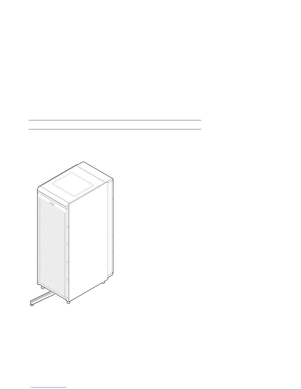
1.1 Cabinet
Figure 1–1 shows the H9A10 cabinet with the stabilizer extended.
Figure 1–1 Cabinet
PK-0625-96
1-2 Configuration and Installation Guide
Page 13

About the Cabinet
The cabinet contains the following components:
•
Cabinet panel with fan and AC power-on LEDs
•
Flushing fans
•
Two AC power controllers, each with an AC circuit breaker
•
Vertical mounting rails
•
Stabilizer bar
•
Wrist strap for static discharge protection
Cabinet Variants
The H9A10 cabinet has two variants. The H9A10-EL (domestic) cabinet contains
two 120 V power controllers, each with 10 NEMA 5-15R outlets. The H9A10-EM
(European) cabinet has two 240 V power controllers equipped with 12 IEC C13
outlets.
Cabinet Configuration Rules
•
The maximum number of system drawers is three.
•
The maximum number of StorageWorks shelves in a one-system drawer cabinet
is eight.
•
The maximum number of StorageWorks shelves in a two-system drawer cabinet
is six.
•
The maximum number of StorageWorks shelves in a three-system drawer cabinet
is two.
Configuration Rules 1-3
Page 14
1.2 System Drawer Configuration Rules (Cabinet)
The H9A10 (RETMA) cabinet rails have a total of 34 U-units with 102 mounting
holes. Table 1-1 gives the mounting holes to be used for a cabinet containing one
to three system drawers.
Figure 1–2 System Drawer Mounting Holes
61
60
59
37
36
35
13
12
11
Front
Rear
H9A10
Drawer 3
Drawer 2
Drawer 1
PK-0629-97
1-4 Configuration and Installation Guide
Page 15

The H9A10 cabinet rails have a total of 34 U-units of vertical mounting height. Each
U-unit is 1.75 inches in length. When you install a system drawer, begin counting
the mounting holes from the rail bottom to top. According to how many system
drawers you install, mark off the mounting holes listed in Table 1-1.
Table 1-1 H9A10 System Drawer Mounting Holes
One System Drawer Two System Drawers Three System Drawers
11, 12, 13 First: 11, 12, 13 First: 11, 12, 13
Second: 35, 36, 37 Second: 35, 36, 37
Third: 59, 60, 61
Configuration Rules 1-5
Page 16

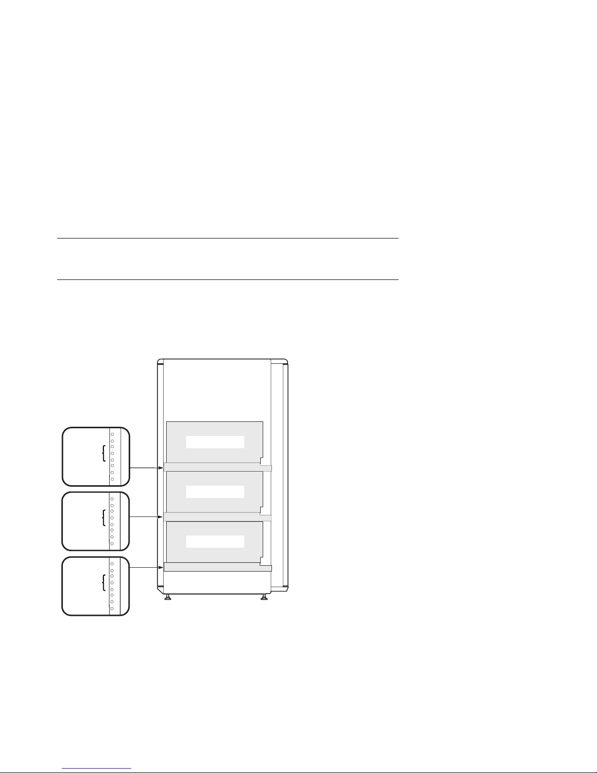
1.3 Shelf Configuration Rules (Cabinet)
The maximum number of StorageWorks shelves is eight in a one-system drawer
cabinet. The maximum number of StorageWorks shelves is six in a two-system
drawer cabinet. Figure 1–3 shows shelf placement in a two-system drawer
cabinet. Figure 1–4 shows shelf placement in a one-system drawer cabinet.
Figure 1–3 Shelves in Two-System Drawer Cabinet
(97)
(94)
(91)
(85)
(82)
(79)
(73)
(70)
(67)
Front
1
2
5
Drawer 2
Drawer 1
(97)
(94)
(91)
Rear
(85)
3
4
6
(82)
(79)
(73)
(70)
(67)
PK-0640-97
1-6 Configuration and Installation Guide
Page 17
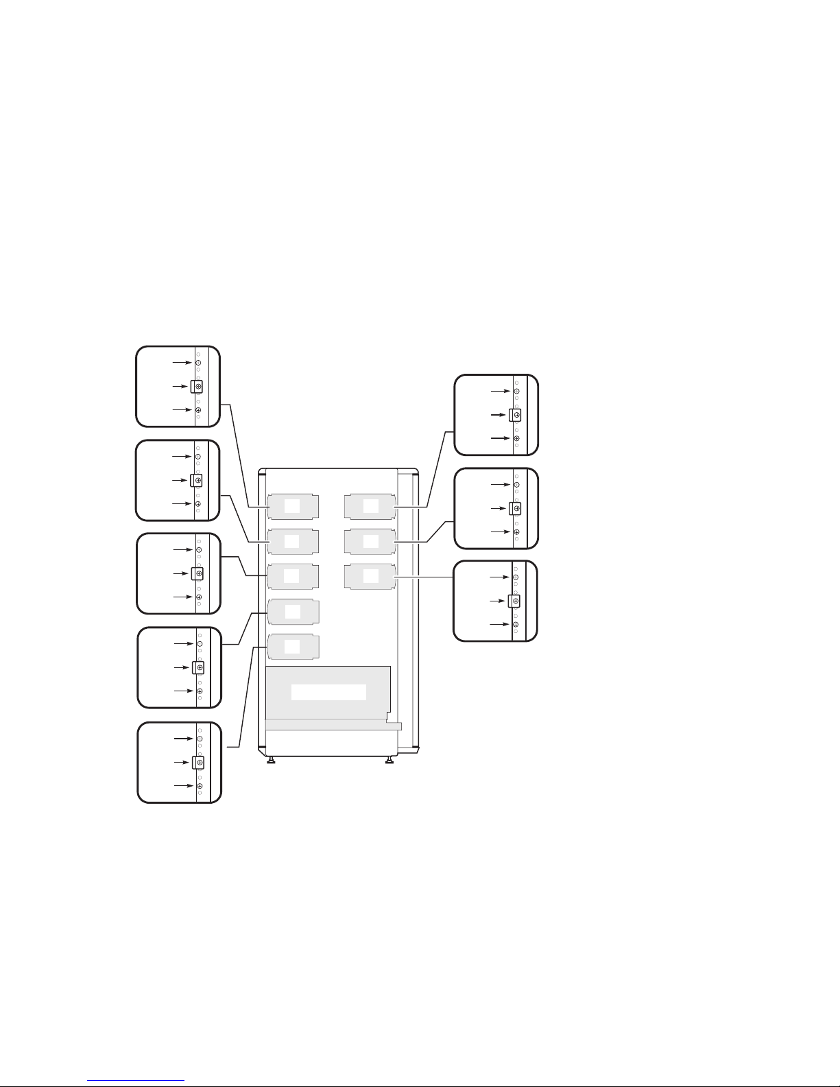
Figure 1–4 Shelves in One-System Drawer Cabinet
(97)
(94)
(91)
(85)
(82)
(79)
(73)
(70)
(67)
(61)
(58)
(55)
(49)
(46)
(43)
Front
1
2
5
7
8
Drawer 1
(97)
(94)
(91)
Rear
(85)
3
4
6
(82)
(79)
(73)
(70)
(67)
PK-0640A-97
Configuration Rules 1-7
Page 18
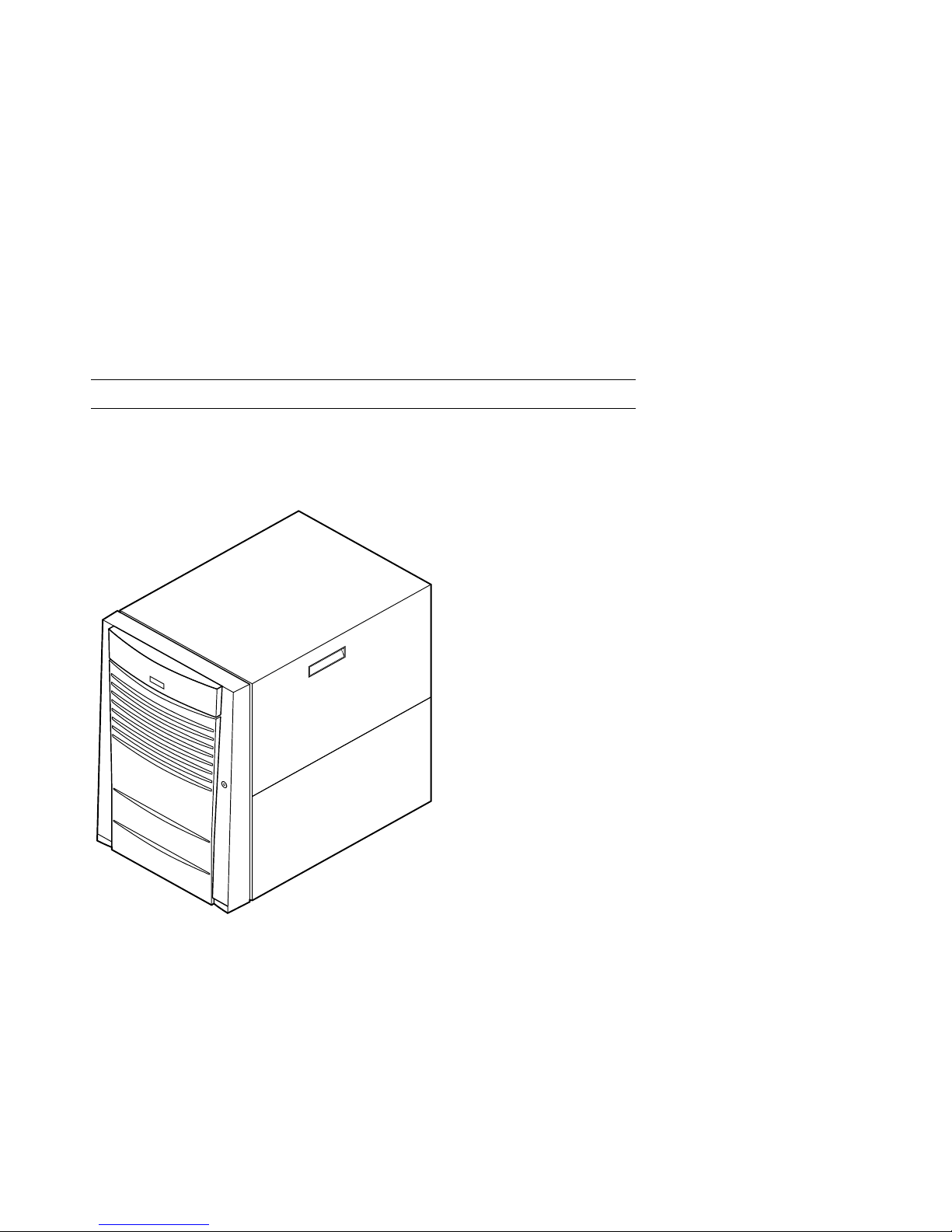
1.4 Pedestal
Figure 1–5 shows the pedestal.
Figure 1–5 Pedestal
1-8 Configuration and Installation Guide
PK-0604-96
Page 19

Pedestal Configuration Rules
•
One system drawer is installed in the pedestal.
•
The maximum number of StorageWorks shelves is three.
Configuration Rules 1-9
Page 20
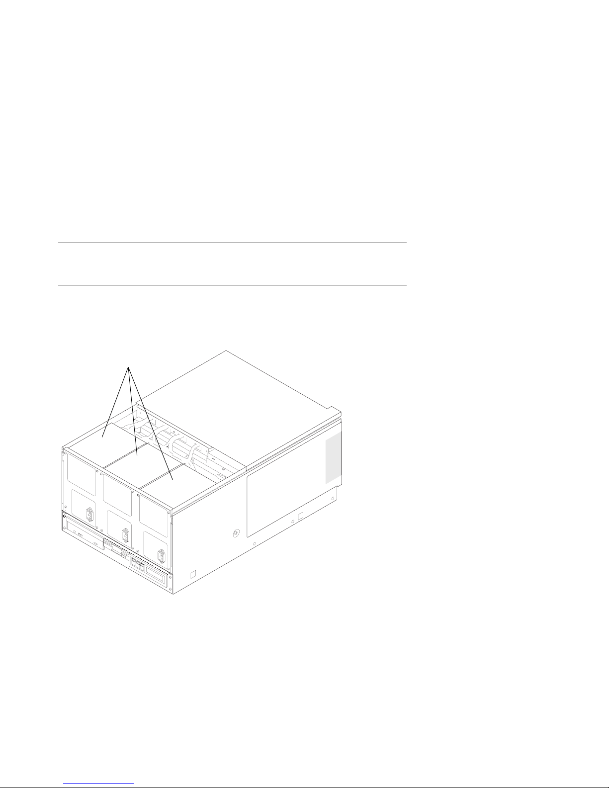
1.5 System Drawer Power System
The system drawer contains one to three power supplies and distribution cables.
Figure 1–6 shows the power components in the system drawer. Two AC power
controllers complete the power system. See Section 1.6.
Figure 1–6 System Drawer Power Components
Power Supplies
First
Third
Second
1-10 Configuration and Installation Guide
PK-0657-96
Page 21

About the Power System
•
A system drawer can contain up to three power supplies. The correct position of
the three power supplies is shown in Figure 1–6.
•
One power supply is required in a system with one or two CPUs.
•
A second power supply is required for N+1 redundancy in a single- or dual-CPU
system.
•
Two power supplies are required in a system with three or more CPUs.
•
Two power supplies are required in a system with two PCI card cages.
•
A third power supply is required for N+1 redundancy in a system with three or
more CPUs.
•
A power harness connects the power supplies to the system motherboard, PCI
motherboard, system fans, and drives.
NOTE: Three power supplies provide N+1 redundancy in AlphaServer 4100 systems
with three or four CPUs and in AlphaServer 4000 systems with two PCI card
cages.
Configuration Rules 1-11
Page 22
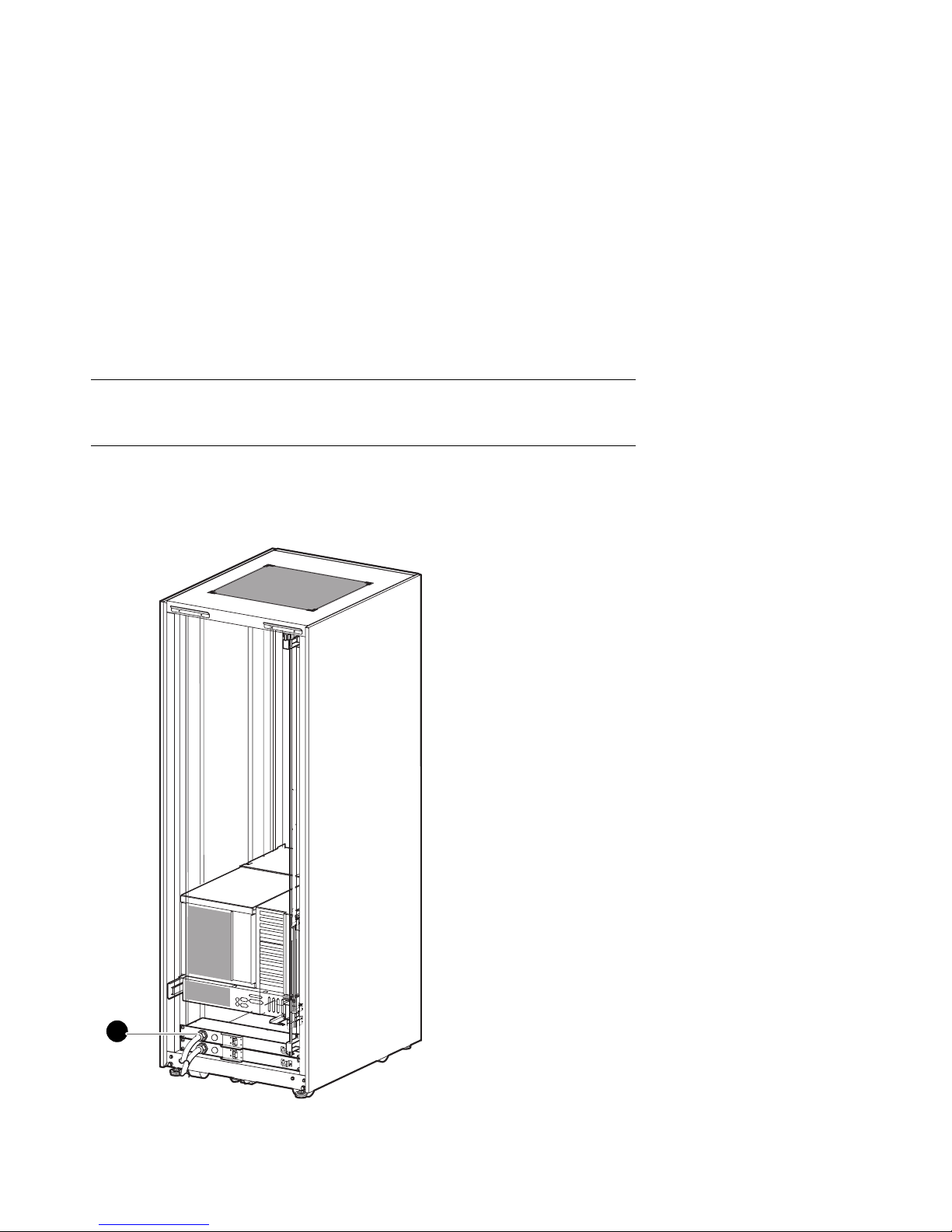
1.6 Cabinet Power System
Figure 1–7 shows the two AC power controllers located at the bottom rear of the
cabinet. The system drawer power cable(s) connect to the controllers. The
controller power cables plug into a wall outlet.
Figure 1–7 Cabinet Power Controllers
1
1-12 Configuration and Installation Guide
PK-0692-97
Page 23
The power controllers connect to an AC wall outlet. Each controller has a main
power switch and 10 outlets for system drawers, StorageWorks shelves, and fan tray.
When connecting system components to the controllers, note that system drawer
power cables are gray; StorageWorks shelf power cables and fan tray power cables
are gray. Configuration rules are:
•
A system drawer contains one to three power supplies; each power supply has
one power cable that connects to a power controller.
•
A StorageWorks shelf has one power cable; a shelf equipped with a redundant
power supply has two power cables.
•
Connect all system drawer power cables to the same AC power controller.
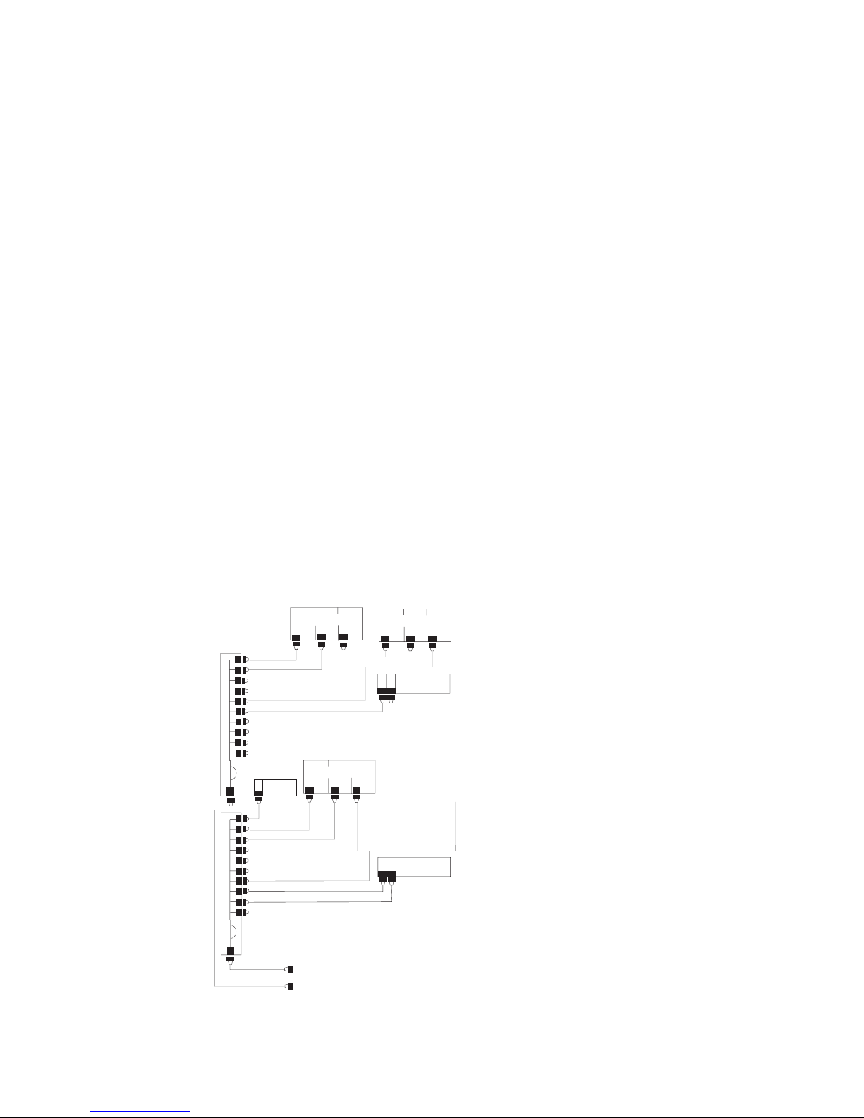
•
If a cabinet has three system drawers, connect the power cables as shown in
Figure 1–8.
Figure 1–8 Power Connections for Three-Drawer Cabinet
Power
Controller
Power
Controller
Fantray
Drawer 2
Drawer 1
To Wall Outlets
Drawer 3
StorageWorks
StorageWorks
PK0695-97
Configuration Rules 1-13
Page 24
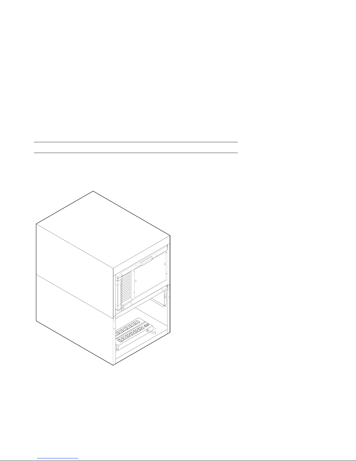
1.7 AC Power Strips in the Pedestal
Figure 1–9 shows the pedestal with two AC power strips installed.
Figure 1–9 Pedestal with AC Power Strips
1-14 Configuration and Installation Guide
PK-0623-96
Page 25

In pedestal systems, both AC power strip cables plug directly into a wall outlet.
Configuration rules are:
•
In North American models: one system drawer and one StorageWorks shelf per
AC power strip
•
In European models: one system drawer and two StorageWorks shelves per AC
power strip
•
In Japanese models: one system drawer and three StorageWorks shelves per AC
power strip
•
A second AC power strip is required if you install a third StorageWorks shelf in
a North American or Japanese model.
•
The maximum number of AC power strips is two.
Configuration Rules 1-15
Page 26
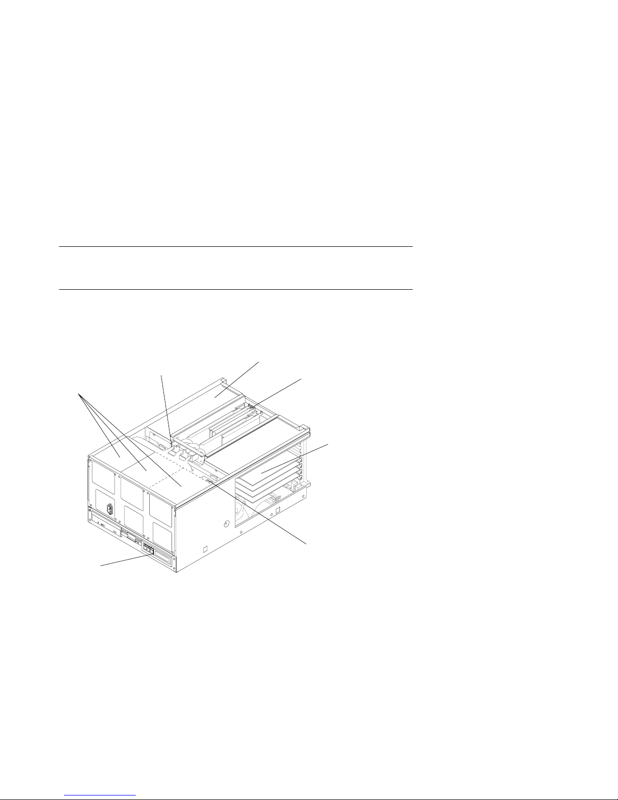
1.8 AlphaServer 4000 System Drawer
Figure 1–10 shows the components of the AlphaServer 4000 system drawer. See
Section 1.8.1 for system motherboard configuration rules. See Section 1.8.2 for
PCI motherboard configuration rules.
Figure 1–10 AlphaServer 4000 System Drawer Components
Power Supplies
Control
Panel
Power Cable
Optional PCI Card Cage
CPU and Memory
Modules
PCI Card Cage
Fans
PK-0688-97
1-16 Configuration and Installation Guide
Page 27
The AlphaServer 4000 system drawer contains the following components:
•
CPU card cage containing the system motherboard, CPU modules, memory
modules, and a system bus-to-PCI bus bridge module
•
A PCI card cage containing a PCI motherboard and PCI and EISA modules
•
An optional PCI card cage with a system bus-to-PCI bus bridge module (the
optional PCI card cage contains only PCI modules)
•
Power supplies and fans
•
Control panel
In a cabinet system, the control panel is at the bottom front of the system drawer. In
a pedestal system, the control panel is located at the top front of the enclosure.
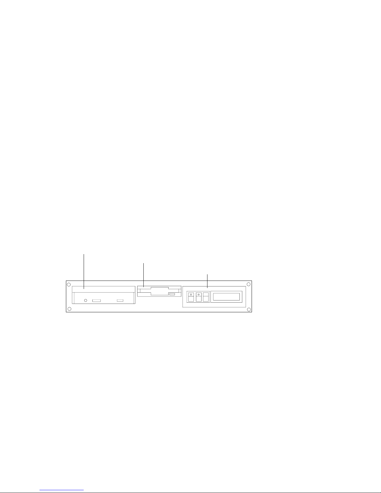
Figure 1–11 AlphaServer 4000 Control Panel
CD-ROM Drive
Diskette Drive
Control Panel
PK-0645D-96
Configuration Rules 1-17
Page 28
1.8.1 AlphaServer 4000 System Motherboard
The AlphaServer 4000 system motherboard has slots for the CPU, memory, and
I/O bridge modules.
Figure 1–12 AlphaServer 4000 System Motherboard
IOD2/3
CPU1
CPU0
IOD0/1
MEM1H
MEM0H
MEM0H
MEM0L
PK-0686-96
1-18 Configuration and Installation Guide
Page 29

AlphaServer 4000 System Motherboard
•
The system motherboard has slots for two processor modules.
•
The first processor module must occupy slot CPU0.
•
The system motherboard has slots for four memory modules (two memory pairs).
•
Memory modules must be configured in matched pairs.
•
When large memory pairs are configured with smaller memory pairs, the largest
memory modules must be installed in the lowest order slots.
•
The system motherboard has two slots for I/O.
•
The power control module (PCM), located on the system motherboard, monitors
voltages, CPU fan RPMs, system fan RPMs, and internal air temperature.
Configuration Rules 1-19
Page 30
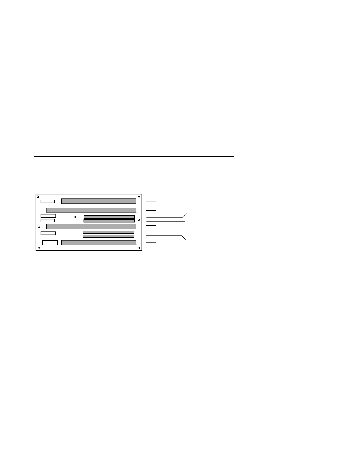
1.8.2 AlphaServer 4000 I/O Interface
The I/O i nt e r f a c e consists of one system bus-to-PCI bus bridge module and a PCI
motherboard. The bridge module is the logical and physical connection from the
system motherboard to the PCI motherboard in the card cage. An optional PCI
card cage is also available. The server control module provides ports for the
console terminal, keyboard, mouse, and other components.
Figure 1–13 AlphaServer 4000 PCI Motherboards
PCI1-5
PCI1-4
PCI1-3
PCI1-2
PCI0-5
EISA-3
PCI0-4
EISA-2
PCI0-3
EISA-1
PCI0-2
PCI3Slot5
PCI3Slot4
PCI3Slot3
PCI3Slot2
PCI2Slot5
PCI2Slot4
PCI2Slot3
PCI2Slot2
1
2
3V 5V 5V
1-20 Configuration and Installation Guide
PK-0687-97
Page 31

AlphaServer 4000 I/O Interface Configuration Rules
•
The bridge modules connect the system motherboard to the PCI motherboard;
they are in slots IOD0/1 and IOD2/3 on the system motherboard.
•
The VGA module must be in a PCI0 slot.
•
The base PCI card cage has a PCI motherboard with five slots for PCI options
and three PCI/EISA combination slots.
•
The optional PCI card cage has a PCI motherboard with eight slots for PCI
options only.
•
In a dual PCI card cage system, PCI motherboards support four PCI buses and
one EISA bus.
Figure 1–13 shows the two PCI motherboards. At the rear of the system drawer, the
base PCI motherboard (
motherboard (
➋) is located at the right side.
➊) is located at the left side of the drawer; the optional PCI
Server Control Module
The server control module, located at the rear of the system drawer, has ports for the
following devices: terminal (COM1), keyboard, mouse, printer, modem, 12V power,
and an additional communications port (COM2).
Figure 1–14 Server Control Module Ports
Keyboard
Port
12V Pwr
Mouse
Port
COM1
Port
COM2
Port
Parallel
Port
Modem
PK-0624-96
Configuration Rules 1-21
Page 32

1.9 AlphaServer 4100 System Drawer
Figure 1–15 shows the components of the AlphaServer 4100 system drawer. See
Section 1.9.1 for system motherboard configuration rules. See Section 1.9.2 for
PCI motherboard configuration rules.
Figure 1–15 AlphaServer 4100 System Drawer Components
Power Cable
CPU and Memory
Power Supplies
Modules
PCI Modules
Control
Panel
1-22 Configuration and Installation Guide
Fans
PK-0656-96
Page 33

The AlphaServer 4100 system drawer contains the following components:
•
CPU card cage containing the system motherboard, CPU modules, memory
modules, and the system bus-to-PCI bus bridge module
•
PCI card cage containing PCI motherboard and PCI and EISA modules
•
Power supplies and fans
•
Control panel
In a cabinet system, the control panel is at the bottom front of the system drawer. In
the pedestal system, the control panel is located at the top front of the enclosure.
Figure 1–16 AlphaServer 4100 Control Panel
CD-ROM Drive
Diskette Drive
Control Panel
PK-0645D-96
Configuration Rules 1-23
Page 34

1.9.1 AlphaServer 4100 System Motherboard
The AlphaServer 4100 system motherboard has four processor slots, eight
memory slots, and one I/O slot.
Figure 1–17 AlphaServer 4100 System Motherboard
CPU3
Mem1H
CPU2
Mem1L
Mem3L
Mem2L
CPU1
Mem0H
Mem3H
Mem2H
CPU0
Mem0L
1-24 Configuration and Installation Guide
IOD01
PK-0614-96
Page 35

AlphaServer 4100 System Motherboard
•
The system motherboard has slots for four processor modules.
•
The first processor module must occupy slot CPU0.
•
The system motherboard has slots for eight memory modules (four memory
pairs).
•
Memory modules must be configured in matched pairs.
•
When large memory pairs are configured with smaller memory pairs, the largest
memory modules must be installed in the lowest order slots.
•
The system motherboard has one slot for I/O.
•
The power control module (PCM), located on the system motherboard, monitors
voltages, CPU fan RPMs, system fan RPMs, and internal air temperature.
Configuration Rules 1-25
Page 36

1.9.2 AlphaServer 4100 I/O Interface
The I/O interf ace consists of the system bus-to-PCI bus bridge module and the
PCI motherboard. The bridge module is the logical and physical connection
from the system motherboard to the PCI motherboard. The server control
module provides ports for the console terminal, keyboard, mouse, and other
components.
Figure 1–18 AlphaServer 4100 PCI Motherboard
PCI1-5
PCI1-4
PCI1-3
PCI1-2
PCI0-5
EISA-3
PCI0-4
EISA-2
PCI0-3
EISA-1
PCI0-2
1-26 Configuration and Installation Guide
PK-0615-96
Page 37

I/O Interface Configuration Rules
•
The bridge module connects the system motherboard to the PCI motherboard; it
is in slot IOD0/1 on the system motherboard.
•
The VGA module must be in a PCI0 slot.
•
The PCI motherboard supports two PCI 64-bit buses and one EISA bus.
PCI and EISA Slots
As shown in Figure 1–18, the PCI motherboard has five dedicated PCI slots and three
slot pairs with connectors for a PCI option and an EISA option. You can install an
option into only one member of each pair. Maximum configurations are:
•
Eight PCI options using the dedicated PCI slots and the PCI connectors in the
three slot pairs. No EISA options can be installed with this configuration.
•
Five PCI options using the dedicated PCI slots and three EISA options using
EISA connectors on the three slot pairs.
NOTE: Multicard options, such as the CIPCA-AA storage adapter, which uses both
one PCI and one EISA slot, or the CIPCA-BA, which uses two PCI slots, take up two
of the eight available option slots.
Server Control Module
The server control module, located at the rear of the system drawer, has ports for the
following devices: terminal (COM1), keyboard, mouse, printer, modem, 12V power,
and an additional communications port (COM2). See Figure 1–14.
Configuration Rules 1-27
Page 38

Page 39

Chapter 2
Preparing the Cabinet
This chapter describes how to prepare the cabinet before installing system drawers
and other components. Sections in this chapter include:
• Cabinet Environmental and Power Requirements
• Unpack and Check Cabinet
• Remove Cabinet from Pallet
• Stabilize the Cabinet
• Joining Two Cabinets
Preparing the Cabinet 2-1
Page 40

2.1 Cabinet Environmental and Power
Requirements
Figure 2–1 shows the clearance area necessary for service access.
Figure 2–1 Cabinet Service Area
1 M
(39 in.)
Front
1 M
(39 in.)
Top
Rear
1 M
(39 in.)
1 M
(39 in.)
PK-0631-96
2-2 Configuration and Installation Guide
Page 41

Table 2–1 lists the environmental requirements. Table 2–2 lists the power
requirements.
Table 2–1 Cabinet Environmental Specifications
Specification Measurement
Operating temperature 10–35°C (50–95°F)
Relative humidity (noncondensing) 20–90%
Maximum operating altitude 3050 m (10,000 ft)
Minimum operating clearance
Front 60 cm (24 in.)
Rear 60 cm (24 in.)
Table 2–2 Cabinet Power Requirements
Specification Measurement
Maximum current rating 24 A
Operating voltage range 100–120 VAC (North American)
Maximum power consumption Configuration-specific
Operating frequency range 50 Hz to 60 Hz
Tools Required
You will need the following tools to install components in the cabinet:
• Phillips screwdriver
• Adjustable wrench
220–240 VAC (Europe)
Preparing the Cabinet 2-3
Page 42

2.2 Unpack and Check Cabinet
Check to ensure that all system equipment is at the installation site. Then,
unpack the equipment.
Figure 2–2 Cabinet System Inventory
Check Equipment
Against Shipping List
Incomplete or
Damaged
Shipment
No
Missing or
Incorrect
Equipment
No
Continue Unpacking
Yes
Yes
Contact Carrier
Enter in LARS Report
Notify Customer
Contact
Unit Manager
PK-0652-96
2-4 Configuration and Installation Guide
Page 43

If you find a damaged container or package, notify the carrier.
Compare items listed on the Product Delivery Document with the packing slip
contained in a plastic envelope on the shipping box. Items should be compared
throughout the installation procedure as boxes are unpacked and cabinets opened.
It is important to record information on damaged or opened containers on the Labor
Activity Reporting (LARS) form.
Preparing the Cabinet 2-5
Page 44

2.3 Remove Cabinet from Pallet
Check the cabinet for external damage. Remove the four shipping brackets that
attach the cabinet to the pallet. Insert the ramps on the front of the pallet and
remove the cabinet.
Figure 2–3 Removal from Pallet
2-6 Configuration and Installation Guide
PK-0649-96
Page 45

WARNING: At least two people are required to remove the cabinet from the pallet.
WARNING: Serious injury may result if the cabinet is improperly handled or proper
safety conditions are not met.
1. Check the cabinet sides, top, and front and rear doors for damage. Report any
damage to the cabinet to the customer and your unit manager. Stop unpacking
until the customer gives you permission to continue.
2. Using an adjustable wrench, remove the four bolts and shipping brackets that
hold the cabinet leveler feet to the pallet.
3. The leveler feet are lowered to the pallet surface for shipment. Using the
adjustable wrench, raise the feet to the uppermost position before removing the
cabinet from the pallet (see Figure 2–5).
4. Attach the ramps by fitting the prongs into the holes on the front of the pallet.
Place the ramps so that the runners are on the inside. Align the arrows on the
ramps and pallet.
5. With two people working together (one in front and one in back) slowly roll the
cabinet off the pallet down the ramps. Move the cabinet into position.
Preparing the Cabinet 2-7
Page 46

2.4 Stabilize the Cabinet
The cabinet stabilizer bar is attached to the bottom of the cabinet. After
removing the cabinet from the pallet, lower the cabinet leveler feet and then pull
out the stabilizer bar.
Figure 2–4 Using the Cabinet Stabilizer Bar
PK-0625-96
2-8 Configuration and Installation Guide
Page 47

1. Using an adjustable wrench or your hand, lower and adjust the leveler feet (see
Figure 2–5). Once the cabinet is level, lock each of the leveler feet in place by
tightening the locknut at the top of each foot.
2. At the front of the cabinet, pull out the stabilizer bar from underneath the
cabinet (see Figure 2–4). Adjust the leveler foot at the end of the stabilizer bar.
WARNING: Only DIGITAL Customer Service representatives or customer
maintenance personnel who are familiar with computer hardware
should slide system drawers out of the cabinet. Personnel should be
experienced and trained in installing computers and related equipment.
Before pulling a system drawer out, make sure that the stabilizer bar is
fully extended; then adjust the leveler foot at the end of the bar so that
it touches the floor.
Figure 2–5 Leveler Foot Adjustment
Screw
Leveler
Foot
PK-0643-96
Preparing the Cabinet 2-9
Page 48

2.5 Joining Two Cabinets
First, position the two cabinets side by side. Then, remove the inner side panels
from each cabinet. Finally, install the joiner kit hardware and attach the
cabinets together.
Figure 2–6 Side Panel Removal
2
1
2-10 Configuration and Installation Guide
PK-0647-96
Page 49

1. Position the cabinets side by side.
2. To remove a side panel, remove the two M5 screws at the bottom front and rear
of the cabinet (see
3. Remove the side panel by lifting it up and away from the cabinet. The side
panel rests on the hanger bracket located at the top of the cabinet (see
➊).
➋).
4. Repeat steps 2 and 3 on the other cabinet. Install the keybuttons (see
Figure 2–7 Installing the Joiner Hardware
5
6
4
8
➌).
3
7
PK-0648-96
Preparing the Cabinet 2-11
Page 50

5. Install a black bracket at the upper front rail area in one cabinet (see
6. Install the top trim piece using two Phillips screws (see
7. Push the cabinets together.
8. Install a black bracket (
cabinets by bolting the brackets together.
9. Repeat the bracket installation at the space provided at the bottom rear of the
cabinet (see
10. Install the front barrier piece by resting it on the keybutton (step 5) and attaching
it to the cabinet top (see
11. Level the cabinets (see Figure 2–5).
➐).
➏) in the same area in the other cabinet. Attach the
➑).
➎).
➍).
2-12 Configuration and Installation Guide
Page 51

Chapter 3
Preparing the Pedestal
This section gives environmental requirements and unpacking guidelines for the
pedestal. Sections include:
• Pedestal Environmental and Power Requirements
• Unpack and Check Pedestal
Preparing the Pedestal 3-1
Page 52

3.1 Pedestal Environmental and Power
Requirements
Figure 3–1 shows the clearance area necessary for service access.
Figure 3–1 Pedestal Service Area
60 cm
(2 ft)
Front
60 cm
(2 ft)
Top
Rear
60 cm
(2 ft)
60 cm
(2 ft)
PK-0606-96
3-2 Configuration and Installation Guide
Page 53

Table 3–1 lists the environmental specifications. Table 3–2 lists the power
requirements.
Table 3–1 Pedestal Environmental Specifications
Specification Measurement
Operating temperature 10–35° C (50–95° F)
Relative humidity (noncondensing) 20–90%
Maximum operating altitude 3050 m (10,000 ft)
Minimum operating clearance
Front 60 cm (2 ft)
Rear 60 cm (2 ft)
Table 3–2 Pedestal Power Requirements
Specification Measurement
Maximum current rating 12 A (North American)
10 A (Europe)
Typical power consumption 720 watts (AlphaServer 4100 system)
Operating voltage range 100–120/200–240 VAC
Operating frequency range 50 Hz to 60 Hz
AC power 100–120 V, 12 A, single phase (North
Plug type NEMA 5-15P (North America and
550 watts (AlphaServer 4000 system)
America and Japan)
200–240 V, 10 A, single phase (Europe)
Japan)
Preparing the Pedestal 3-3
Page 54

3.2 Unpack and Check Pedestal
Check to ensure that all system equipment is at the installation site. Then,
unpack the equipment.
Figure 3–2 Pedestal System Inventory
Check Equipment
Against Shipping List
Incomplete or
Damaged
Shipment
No
Missing or
Incorrect
Equipment
No
Continue Unpacking
Yes
Yes
Contact Carrier
Enter in LARS Report
Notify Customer
Contact
Unit Manager
PK-0652-96
3-4 Configuration and Installation Guide
Page 55

If you find a damaged container or package, notify the carrier.
Compare items listed on the Product Delivery Document with the packing slip
contained in a plastic envelope on the shipping box. Items should be compared
throughout the installation procedure as boxes are unpacked and cabinets opened.
It is important to record information on damaged or opened containers on the Labor
Activity Reporting (LARS) form.
Preparing the Pedestal 3-5
Page 56

Page 57

Chapter 4
Installing Components in Cabinet
Some cabinet systems are shipped with factory-installed system drawers and
StorageWorks shelves. However, both components may be ordered separately and
slider rail kits are available when installing additional system drawers. This chapter
provides guidelines for installing the system drawers and StorageWorks shelves in a
cabinet. Sections include:
• Installing Slider Rails
• Installing the System Drawer
• Installing a StorageWorks Shelf
Installing Components in Cabinet 4-1
Page 58

4.1 Installing Slider Rails
4.1.1 Attach Slide Assemblies to Cabinet Rails
Figure 4–1 Attaching Slide Assemblies
1
2
5
5
4
3
4
3
4-2 Configuration and Installation Guide
LJ-05545.TI0
Page 59

1. Loosen the three screws and nuts
assemblies (see Figure 4–1). This allows the length of the slide assemblies to be
adjusted between the front and rear mounting rails.
2. Locate the right slide assembly.
3. Place the front slide bracket on the inside of the right front rail and align the
holes from the bottom of the nut plate
right front rail.
4. Install one screw
right front rail. Do not tighten.
5. Place the rear slide bracket on the inside of the right rear rail and align the holes
from the bottom of the nut plate
rear rail.
6. Install one screw and washer in the first hole to secure the rear slide bracket to
the right rear rail. Do not tighten.
7. Install four truss-head screws
the right rear rail. Do not tighten.
8. Tighten the three pan-head screws and hexnuts
bracket to the right slide assembly.
9. Attach the left slide assembly to the left front and rear rails by repeating steps 1
through 8.
10. Tighten all screws only enough to allow play for the slides to align when the
slide tray is installed in the cabinet.
➌ and one washer ➍ to secure the front slide bracket to the
➊ securing the rear slide bracket to the slide
➋ with the four slide bracket holes on the
➋ with the four slide bracket holes on the right
➎ to secure the rear slide bracket and nut plate to
➊ that secure the right rear slide
Installing Components in Cabinet 4-3
Page 60

4.1.2 Mount Slide Tray on Slides
Figure 4–2 Mounting the Slide Tray
2
4
1
2
3
LJ-05546.TI0
4-4 Configuration and Installation Guide
Page 61

1. Fully extend the slides, then lift the slide tray
➋ fit into the front end ➌ of the slides (see Figure 4–2).
races
2. Push the slide tray into the slides until it stops. Push in on the two locking
➍ if necessary and then push the slide tray into the cabinet.
levers
3. Ensure the slide tray slides smoothly in and out of the cabinet.
4. Tighten the screws that secure each of the rear side brackets and nut plates to the
rear rails.
5. Tighten the screws that secure each of the front side brackets and nut plates to
the front rails.
➊ and position it so that the inner
Installing Components in Cabinet 4-5
Page 62

4.2 Installing the System Drawer
4.2.1 Mount the System Drawer on Slide Tray
Figure 4–3 Mounting System Drawer on Slide Tray
3
3
1
4
5
2
6
3
2
1
3
4
2
5
1
6
LJ-05547.TI0
4-6 Configuration and Installation Guide
Page 63

WARNING: Before mounting the system drawer on the slide tray, ensure that the
cabinet stabilizer is in place.
WARNING: The system drawer, fully configured, weighs 45 kg (100 lbs). Two
people are required to install the system drawer in the cabinet.
1. Extend the slide tray to its fully extended position. The slide locking levers lock
when the slides are fully extended.
2. Lift the system drawer just above the slide tray and then move it back and onto
the slide tray.
3. Carefully position the system drawer until the four mounting holes in the bottom
of the drawer line up with the four mounting holes in the bottom of the slide
tray.
4. Secure the drawer using four screws
Two cable clamps go on each screw under the left side of the slide tray and one
cable clamp goes on each screw under the right side of the slide tray.
5. Install the cable clamps
the left and right sides using flat washers
go on the left stud and one cable clamp goes on the right stud.
➍ on the two studs located underneath the slide tray on
➊ , flat washers ➋ , and cable clamps ➌.
➎ and kepnuts ➏. Two cable clamps
Installing Components in Cabinet 4-7
Page 64

4.2.2 Attach the Brackets
Figure 4–4 Attaching the Brackets
8
9
10
8
2
5
4
5
3
1
4
5
6
3
1
3
9
10
4
5
6
8
8
7
LJ-05548.TI0
4-8 Configuration and Installation Guide
Page 65

1. Remove the top screw
panel assembly (see Figure 4–4). Save the screws for later use.
2. Align the two holes at the bottom of the left catch bracket
in the left front edge of the slide tray.
3. Secure the left catch bracket to the slide tray with two truss-head screws
4. Secure the left catch bracket to the system drawer by replacing the screw
removed in step 1.
5. Attach a cable clamp
➊ on the left and right side of the system drawer control
➋ with the two holes
➌.
➍ to each stud on the left catch bracket with flat washers
➎ and kepnuts ➏.
6. Attach a cable clamp to each standoff on the left catch bracket with flat washers
and kepnuts.
7. Align the two holes at the bottom of the right catch bracket
holes in the right front edge of the slide tray.
8. Secure the right catch bracket to the slide tray with two truss-head screws.
9. Secure the right catch bracket to the system drawer by replacing the screw
removed in step 1.
10. Attach a cable clamp to each of the studs on the right catch bracket with flat
washers and kepnuts.
➐ with the two
Installing Components in Cabinet 4-9
Page 66

4.2.3 Install Cable Management Bracket
Figure 4–5 Installing Cable Management Bracket
1
2
2
3
5
3
4
5
4
3
5
4
LJ-05549.TI0
4-10 Configuration and Installation Guide
Page 67

1. At the rear of the cabinet, locate the bracket installation holes shown in Figure
4–5.
2. Install a U-nut over each hole. The thread of the U-nuts should face toward the
inside of the cabinet.
3. Secure the cable management bracket
head screws
4. Secure the three cable clamps
head screws
➋ on each rear rail.
➌ to the rear edge of the slide tray with truss-
➍ and flat washers ➎.
➊ to the rear rails by installing two truss-
Installing Components in Cabinet 4-11
Page 68

4.2.4 Install Interlock Actuator Assembly
Figure 4–6 Installing the Interlock Actuator
1
1. Mount the interlock actuator ➊ on the left rear of the slide tray using two
kepnuts
2. Remove the screws securing the bottom mounting bracket
3. Slide the mounting bracket off the bottom of the vertical bar.
4. Slide the stabilizer bracket
5. Slide the actuator latch
6. Replace the bottom mounting bracket
2. Do not tighten.
7. Secure the stabilizer bracket to the left rear rail with two truss-head screws
8. Position the actuator latch
tighten the two screws to secure the latch to the vertical bar.
9. Tighten the screws to secure the bottom mounting bracket.
4-12 Configuration and Installation Guide
➋ (see Figure 4–6).
➎ onto the bottom of the vertical bar.
➋ onto the bottom of the vertical bar.
➍ and install the screws removed in step
➋ to properly engage the interlock actuator ➌, and
2
LJ-05550.TI0
➍ (see Figure 4–7).
➏.
Page 69

Figure 4–7 Installing Stabilizing Bracket and Latch
A
53
6
6
2
B
1
4
LJ-05551.TI0
Installing Components in Cabinet 4-13
Page 70

4.2.5 Route the Power Cables
Figure 4–8 Routing Power Cables
6
2
4
1
3
4
5
LJ-05553.TI0
4-14 Configuration and Installation Guide
Page 71

1. If necessary, remove the old power cables from the system. You must use the
power cables shipped with the slider shelf assembly.
2. Fully extend the slide tray from the cabinet (see Figure 4–8).
3. Connect one end of the power cable(s)
front of the system drawer.
NOTE: When routing a power cable, you must remove the cable clamp, insert
the cable in the clamp, and then reinstall it.
4. If the system has one power supply, route the power cable through the inside
cable clamps
5. If the system has a second power supply, route the power cable through the
outside cable clamps on the left catch bracket.
6. Route the power cable through the cable clamps
the slide tray. Then route it through the two cable clamps on the left rear edge
of the slide tray
7. Tie-wrap the cable to the cable management bracket
enough slack in the cable to prevent stress between the slide tray cable clamp
and the cable management bracket.
8. If the system has a third power supply, route the power cable through the cable
clamps on the right catch bracket. Then continue to route the cable as you did
the others, using the cable clamps underneath the right side of the slide tray.
➌ on the left catch bracket.
➎.
➊ to the AC input receptacle(s) ➋ on the
➍ underneath the left side of
➏. Ensure that there is
Installing Components in Cabinet 4-15
Page 72

4.3 Installing a StorageWorks Shelf
The number o f Storag eWorks she lves yo u can instal l depe nds on the number of
system drawers in the cabinet. For example, there is space for eight
StorageWorks shelves in a cabinet with one system drawer. See Figure 4–9.
Figure 4–9 Sample Cabinet Configuration
3
7
8
Front
1
2
5
4
6
Rear
PK-0691-97
4-16 Configuration and Installation Guide
Page 73

1. In the H910A cabinet, install the StorageWorks shelf mounting rails as shown in
Figure 4–10.
2. Attach the U-nuts to the appropriate mounting holes.
3. Attach the mounting rail using two screws inserted into the two U-nut mounting
holes.
4. Attach the front holding bracket and the two additional screws.
5. Attach the other holding bracket.
6. Install the StorageWorks shelf by sliding it onto the mounting rails.
7. Connect the shelf power cable to an AC power strip. Connect the shelf signal
cable to the SCSI controller in the PCI card cage.
Figure 4–10 Installing Shelf Mounting Rails in H910A Cabinet
Front
PK-0635-96
Installing Components in Cabinet 4-17
Page 74

Page 75

Chapter 5
Installing StorageWorks Shelves in
Pedestal
Up to three StorageWorks shelves can be installed in the pedestal.
• Install the StorageWorks Shelf
Installing StorageWorks Shelves in Pedestal 5-1
Page 76

5.1 Install the StorageWorks Shelf
You can install a maximum of three StorageWorks shelves in a pedestal. There
is space for two shelves in the front of the pedestal and one in the rear.
Figure 5–1 Installing a StorageWorks Shelf
5-2 Configuration and Installation Guide
PK-0658-96
Page 77

1. Remove the top cover from the pedestal.
2. Slide the StorageWorks shelf into the pedestal base (see Figure 5–1). The
pedestal base contains three sets of support rails for the StorageWorks shelves.
3. Attach the shelf with the hardware included with the option.
4. Connect the StorageWorks signal cable to the PCI SCSI port.
5. Connect the StorageWorks power cable to the AC power strip.
6. Replace the top cover.
Installing StorageWorks Shelves in Pedestal 5-3
Page 78

Page 79

Chapter 6
Making Connections
This chapter describes how to connect system components and devices. Sections
include:
• Connecting a Serial Terminal
• Connecting a Graphics Monitor
• Connecting the Remote Console Monitor
• Connecting the Ethernet Cable
• Connecting a StorageWorks Shelf
1
1
This section shows a standard serial terminal. This terminal is connected to a single system
drawer. Also available is the optional H4020-AA System Management Kit, a single terminal
which mounts in the cabinet and can connect up to eight system drawers.
Making Connections 6-1
Page 80

6.1 Connecting a Serial Terminal
Figure 6–1 shows the cabinet and a serial terminal. Connect the terminal to the
COM1 port at the rear of the system drawer as shown in Figure 6–2. K e yboard,
mouse, and printer ports are located near the console terminal port.
Figure 6–1 Cabinet and Console Terminal
6-2 Configuration and Installation Guide
PK-0655-96
Page 81

1. Unpack the serial terminal, if required. Locate the console terminal signal
cable.
2. Connect one end of the cable to the COM1 port located at the rear of the system
drawer (see Figure 6–2). Connect the other end of the cable to the console
terminal, which connects to a 25-pin connector.
3. Connect the keyboard cable to the keyboard port at the rear of the serial
terminal.
4. Connect the printer cable to the parallel port.
Figure 6–2 COM1, Serial Terminal Port
Keyboard
Port
Port
Parallel
Port
PK-0624A-96
COM1
Making Connections 6-3
Page 82

6.2 Connecting a Graphics Monitor
Figure 6–3 shows the ports used t o c o nne c t a graphics m o ni t or. You co nne ct the
graphics monitor to the VGA module in the PCI card cage. Keyboard, mouse,
and printer ports are located at the rear of the system drawer.
Figure 6–3 Graphics Monitor Ports
Graphics Monitor
Connector
Keyboard Port
Mouse Port
6-4 Configuration and Installation Guide
Parallel Port
PK-0663-96
Page 83

1. Unpack the graphics monitor, if required. Locate the signal cable.
2. Connect one end of the cable to the VGA port in the PCI card cage. Connect the
other end of the cable to the graphics monitor, which connects to a 25-pin
connector.
3. Connect the keyboard cable to the keyboard port at the rear of the system
drawer.
4. Connect the mouse cable to the mouse port.
5. During power-up, you may want to capture the power-up display on a serial
printer. To do this, connect a serial printer to the parallel port.
Making Connections 6-5
Page 84

6.3 Connecting the Remote Console Monitor
Figure 6–4 shows the connections you make to enable the remote console
monitor (RCM) in a pedestal system. The external 12V power supply is not
required in cabinet systems. See the System Drawer User’s Guide for
instructions on how to operate the RCM.
Figure 6–4 Remote Console Monitor Connections
ConsoleTerminal
External
Power
Supply
6-6 Configuration and Installation Guide
Modem
PhoneJack
PK-0651-96
Page 85

1. Connect the external power supply cable to the 12V power port (pedestal
systems only). Connect the other end to a wall outlet (see Figure 6–4).
2. Connect the modem cable to the modem port. Connect the modem to a phone
jack.
Making Connections 6-7
Page 86

6.4 Connecting the Ethernet Cable
If the system includes an Ethernet port, connect the Ethernet cable to the I/O
bulkhead and to the Ethernet transceiver. You can connect ThinWire, AUI, or
twisted-pair Ethernet cables.
Figure 6–5 Ethernet Port
AUI
6-8 Configuration and Installation Guide
ThinWire
Twisted Pair
PK-0660-96
Page 87

1. Connect the transceiver cable to the Ethernet port on the I/O bulkhead (see
Figure 6–5).
2. Connect the other end of the cable to the Ethernet transceiver. See the
appropriate Ethernet transceiver manual for more information.
Making Connections 6-9
Page 88

6.5 Connecting a StorageWorks Shelf
When installing an additional StorageWorks shelf, connect the power cable to
an AC power str ip; connect the si gnal cable to the SCSI controller at the I/O
bulkhead. See Chapter 1 for cabinet and pedestal configuration guidelines.
Figure 6–6 SCSI Port
6-10 Configuration and Installation Guide
PK-0659-96
Page 89

1. Connect the StorageWorks power cable to an AC power strip.
2. Connect the StorageWorks signal cable to the I/O bulkhead at the rear of the
system.
Making Connections 6-11
Page 90

Page 91

Chapter 7
System Power-Up and Verification
This chapter provides an overview of the power-up procedure, LED checks, and
booting. Sections include:
• Verification Overview
• Turn On Power
• Check Power-Up Test Results
• If Power-Up Fails
– Check Control Panel Message
– Check Module LEDs
– Check Cabinet Power and Fan LEDs
• Show Commands for Installation
• Preboot Tasks
– Setting Environment Variables (EVs)
– Running ECU
– Running Utility Programs
– Updating Firmware
• Booting OpenVMS or DIGITAL UNIX
• Booting Windows NT
System Power-Up and Verification 7-1
Page 92

7.1 Verification Overview
Use the following procedure to verify the system after installation.
Figure 7–1 Verification Procedure
1
3
4
Power Up System.
Check Test Results.
Verify SCSI Devices.
2
Perform PreBoot
Boot Operating
System
Tasks
PK-0653-96
7-2 Configuration and Installation Guide
Page 93

➊ When the system powers up, tests run. Verify that all tests have passed by
checking the results in the test display.
➋ Enter the show device command and then check the output against the physical
SBBs (storage building blocks).
➌ Perform preboot tasks such as setting environment variables and running ECU
(EISA Configuration Utility), RCU (RAID Configuration Utility), and LFU
(Loadable Firmware Update).
➍ Boot the operating system.
NOTE: Check all power cable connections from the system components to the AC
power controllers. Make sure that both AC power controller circuit breakers are
On.
NOTE: Before you power up the system, you may want to connect a printer to the
parallel port (located at the rear of the system drawer) to capture the power-up test
results.
System Power-Up and Verification 7-3
Page 94

7.2 Turn On Power
Check all power cable connections. Check that the AC power controller circuit
breakers are On. Press in the Halt button on the system drawer control panel to
force halting at the SRM console prompt. Then, press the Power button. See
Figure 7–2.
Figure 7–2 Control Panel
Power
Halt
Reset
PK-0645C-96
7-4 Configuration and Installation Guide
Page 95

1. Press in the control panel Halt button to force the SRM console (this will
override the SRM console os_type environment variable setting). The Halt
button LED lights when pressed in.
2. Press the Power button to power up the system. The Power button LED lights
when pressed in.
System Power-Up and Verification 7-5
Page 96

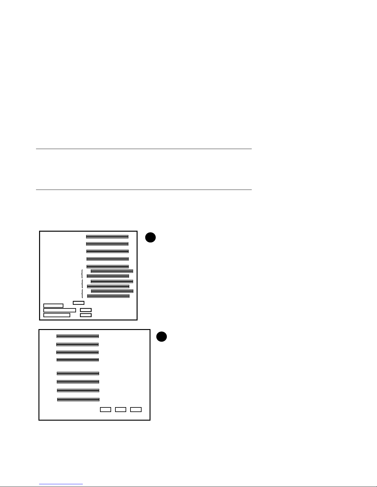
7.3 Check Power-Up Test Results
After powering up the system, testing begins and status messages display on the
console terminal and on the control panel display. Check the test results on the
console terminal. Example 7–1 shows a sample display of test results.
Example 7–1 Test Results
SROM V2.0 on cpu0 ➊ #This section displays
SROM V2.0 on cpu1 #on serial terminals
XSROM V2.0 on cpu1
XSROM V2.0 on cpu0
BCache testing complete on cpu1
BCache testing complete on cpu0
mem_pair0 - 128 MB
mem_pair1 - 128 MB
20..20..21..21..23..24..24..
Memory testing complete on cpu1
Memory testing complete on cpu0
starting console on CPU 0
sizing memory #on both serial and
0 128 MB SYNC
1 128 MB SYNC
starting console on CPU 1
probing IOD1 hose 1 ➒
bus 0 slot 1 - NCR 53C810
bus 0 slot 2 - DEC KZPSA
bus 0 slot 3 - NCR 53C810
bus 0 slot 4 - DECchip 21040-AA
bus 0 slot 5 - DEC PCI MC
probing IOD0 hose 0
bus 0 slot 1 - PCEB
bus 0 slot 4 - DEC PCI FDDI
bus 0 slot 5 - PBXGA-AA
➋ #only.
➌
➍
➎
➏ #This section displays
➐ #graphics terminals.
➑
configuring I/O adapters...
ncr0, hose 1, slot 1, bus 0
kzpsa0, hose 1, slot 2, bus 0
ncr1, hose 1, slot 3, bus 0
tulip0, hose 1, slot 4, bus 0
floppy0, hose 0, slot 0, bus 1
pfi0, hose 0, slot 4, bus 0
7-6 Configuration and Installation Guide
➓
Page 97

System temperature is 24 degrees C ➀
AlphaServer 4100 Console V2.0-1, 24-JUL-1996 10:47:18 ➁
P00>>>
NOTE: If the console and the system are configured in graphics mode (SRM console
environment variable (EV) is set to graphics), test information covered by callouts
➊ through ➏ will not display. If the SRM console EV os_type is set to NT, the
Windows NT AlphaBIOS console will be loaded by the SRM console, unless the
control panel Halt button is depressed. If this is the case, the SRM console ignores
the os_type setting and halts when the SRM power-up initialization and
configuration is completed.
➊ SRM code runs on each CPU. The processor chips are tested and the path to the
system flash ROM is verified. Each CPU then loads XSROM from the system flash
ROM.
➋ XSROM prints banner if it is successfully loaded and started.
➌ XSROM performs local B-cache initialization and testing on each CPU.
➍ XSROM sizes memory via the system IIC bus.
➎ Each CPU participates in memory initialization and testing.
➏ XSROM loads the SRM system console from system flash ROM.
➐ Console starts on the primary CPU and proceeds to re-size memory.
➑ The primary CPU, running console, signals each secondary (running XSROM) to
start console.
➒ The primary CPU probes each PCI bus and the EISA bus to size the system.
➓ The primary CPU configures and initializes those I/O adapters requiring
initialization.
① The system temperature is reported.
➁ The console displays its version banner and console prompt.
For a more detailed description of the test results, see the System Drawer User’s
Guide.
System Power-Up and Verification 7-7
Page 98

7.4 If Power-Up Fails
7.4.1 Check Control Panel Message
If the console prompt does not appear after test results, check the control panel
message. Figure 7–3 shows the four display fields. Table 7–1 lists the
description of each field.
Figure 7–3 Control Panel Display
2 3
1
4
P0 TEST 11 CPU00
The control panel has a LED display (to control brightness, adjust the potentiometer
located above the control panel Reset button). Status messages are displayed during
power-up testing. Test failure information is also displayed.
NOTE: If an error occurs, you may need to reset the system and observe the display
since display error messages are visible for approximately 4 seconds before powerup initialization and testing continues.
NOTE: If nothing is displayed on the control panel display and/or the serial display
terminal, check the module LEDs (see Section 7.4.2). In cabinet systems, check the
power and fan LEDs (see Section 7.4.3).
7-8 Configuration and Installation Guide
PK-0706E-96
Page 99

Table 7–1 Control Panel Display
Field Content Display Meaning
➊ CPU number P0–P3 CPU reporting status
➋ Status TEST Tests are executing
FAIL Failure has been detected
MCHK Machine check has occurred
INTR Error interrupt has occurred
➌ Test number (for
DIGITAL use only)
➍ Suspected device CPU0–3 CPU module number
1
MEM0–3 and
L, H, or *
IOD0 Bridge to PCI bus 0
IOD1 Bridge to PCI bus 1
IOD2 Bridge to PCI bus 2
IOD3 Bridge to PCI bus 3
FROM0 Flash ROM
COMBO COM controller
PCEB PCI-to-EISA bridge
ESC EISA system controller
NVRAM Nonvolatile RAM
TOY Real-time clock
I8242 Keyboard and mouse controller
1
CPU module
2
Memory module
3
Bridge module (PCI 0 & 1)
4
Bridge module (PCI 2 & 3) (16-PCI slot drawer only)
5
PCI motherboard
Memory pair number and low
module, high module, or either
3
3
4
4
5
5
5
5
5
5
2
5
System Power-Up and Verification 7-9
Page 100

7.4.2 Check Module LEDs
Figure 7–4 shows the CPU, bridge module, and power control module LEDs.
Table 7–2 lists LED status following a successful power-up. You can see all
module LEDs from the rear of the system drawer. For more information on
troubleshooting procedures, see the AlphaServer 4000/4100 Service Manual.
Figure 7–4 Module LEDs
Power Control Module LEDs
DCOK_SENSE
PS0_OK
PS1_OK
PS2_OK
TEMP_OK
CPUFAN_OK
SYSFAN_OK
CS_FAN0
CS_FAN1
CS_FAN2
C_FAN3
Normally On
Tested at one-second intervals
Off if power supply not present
or broken
Bridge Module LEDs (IOD 0 & 1)
IOD0 Self-Test Pass
IOD1 Self-Test Pass
POWER_FAN_OK
TEMP_OK
Bridge Module LEDs (IOD 2 & 3)
IOD2 Self-Test Pass
IOD3 Self-Test Pass
CPU LEDs
DC_OK
SROM Oscillator
CPU Self-Test Pass
REGULATOR_OK
(B3004 module only)
PK-0696-97
7-10 Configuration and Installation Guide
 Loading...