

Digital Equipment AlphaServer 2000 Owner's Manual

AlphaServer2000
Owner’sGuide
Order Number: EK–400MP–OP. A01
Digital Equipment Corporation
Maynard, Massachusetts

Preliminary Version, September 1994
First printing, October 1994
Digital Equipment Corporation makes no representations that the use of its
products in the manner described in this publication will not infringe on
existing or future patent rights, nor do the descriptions contained in this
publication imply the granting of licenses to make, use, or sell equipment or
software in accordance with the description.
Possession, use, or copying of the software described in this publication
is authorized only pursuant to a valid written license from Digital or an
authorized sublicensor.
© Digital Equipment Corporation 1994. All Rights Reserved.
The postpaid Reader’s Comments forms at the end of this document request
your critical evaluation to assist in preparing future documentation.
The following are trademarks of Digital Equipment
Corporation: AlphaGeneration, AlphaServer, AXP, DEC, DECchip, DECconnect,
Digital, OpenVMS, StorageWorks, VAX, VT, the AlphaGeneration logo, and the
DIGITAL logo.
OSF/1 is a registered trademark of Open Software Foundation, Inc. PostScript
is a registered trademark of Adobe Systems, Inc. Microsoft Windows and
Microsoft Windows NT are trademarks of Microsoft Corporation.
All other trademarks and registered trademarks are the property of their
respective holders.
S2635
FCC Notice:
This equipment generates and uses radio frequency energy. It has been type
tested and found to comply with the limits for a Class B computing device in
accordance with the specifications in Part 15 of FCC Rules, which are designed
to provide reasonable protection against such radio and television interference
in a residential installation.
Any changes or modifications made to this equipment may void the user’s
authority to operate this equipment.
However, there is no guarantee that interference will not occur in a particular
installation. If this equipment does cause interference to radio or television
reception, the user is encouraged to try to correct the interference.
This document was prepared using VAX DOCUMENT Version 2.1.

EC Notice: This equipment complies with CE Class B requirements.
EU-Hinweis: Dieses Gerät entspricht den EU-Bestimmungen der Klasse B.
Avis de conformité aux normes CEE : Cet équipement est conforme aux
normes CEE pour la classe B.
Acoustics: Preliminary declared values per ISO 9296 and ISO 7779:
Sound Pressure Level
Idle (lightly
Sound Power Level
,B
L
wAd
6.3 45
, dBA (Bystander
L
pAm
Positions)
loaded)
Operating (lightly
6.4 45
loaded)
Idle (fully loaded) 6.4 45
Operating (fully
6.5 45
loaded)
Current values for specific configurations are available from Digital
representatives. 1B=10dBA.
Schallemissionswerte: Verläufige Werteangaben nach ISO 9296 und ISO
7779/DIN EN27779:
Schalldruckpegel
Leerlauf (leicht
Schalleistungspegel
,B
L
wAd
6,3 45
, dBA
L
pAm
(Zuschauerpositionen)
belastet)
Betrieb (voll
6,4 45
belastet)
Leerlauf (leicht
6,4 45
belastet)
Betrieb (voll
6,5 45
belastet)
Aktuelle Werte für spezielle Ausrüstungsstufen sind über die Digital Equipment
Vertretungen erhältlich. 1 B = 10 dBA.


Contents
Preface ..................................................... xiii
1 Basic Operation
Before Using this Guide . . ........................... 1–1
In This Chapter ................................... 1–2
System Features . . ................................... 1–3
Overview ........................................ 1–3
Characteristics . ................................... 1–3
Architecture . . . ................................... 1–5
Environmental and Power Requirements ................... 1–6
In This Section . ................................... 1–6
System Dimensions ................................ 1–6
Environmental Specifications ......................... 1–7
Power Requirements ............................... 1–8
Power Cords . . . ................................... 1–9
Moving the System ................................ 1–10
Repositioning the System . ........................... 1–10
Opening the System Door ........................... 1–11
Turning the System On ................................ 1–12
Overview ........................................ 1–12
Checking System Settings ........................... 1–13
Powering Up the System . ........................... 1–14
Displaying Power-Up Information . . ................... 1–14
Checking the Power-Up Displays . . . ................... 1–16
Preboot Tasks. . ................................... 1–20
Booting an Operating System ........................ 1–23
Autobooting an Operating System . . ................... 1–25
Powering Down the System . . ........................... 1–26
Before You Begin .................................. 1–26
Turning Off DC Power . . . ........................... 1–26
Extended Power-Down (AC Power) . ................... 1–27
Invoking Console Mode ................................ 1–28
v

Console Subsystem. ................................ 1–28
Console Terminal . . ................................ 1–28
Console Mode ..................................... 1–28
Invoking Console Mode ............................. 1–28
Remote Access .................................... 1–29
Switching Between Operating Systems . ................ 1–29
Network Options ..................................... 1–31
Overview ........................................ 1–31
Connecting Peripherals ................................ 1–32
Serial/Parallel Connections . . ........................ 1–32
Terminal Connections .............................. 1–34
Operating Storage Devices .............................. 1–36
Overview ........................................ 1–36
For Additional Information . . ........................ 1–36
Before You Operate Mass Storage Devices ............... 1–36
Identifying Mass Storage Compartments ................ 1–37
Operating Storage Devices . . . ........................ 1–37
Operating a CD–ROM Drive ............................ 1–38
CD–ROM Drive Description . . ........................ 1–38
Caddyless Drive . . . ................................ 1–38
Drive with Caddy . . ................................ 1–40
Inserting and Removing a Compact Disc ............... 1–42
Operating a DAT Tape Drive ............................ 1–46
DAT Description. . . ................................ 1–46
Inserting a Tape. . . ................................ 1–46
Removing a Tape . . ................................ 1–46
Operating a Diskette Drive ............................. 1–48
Diskette Drive Description . . . ........................ 1–48
Inserting a Diskette ............................... 1–48
Removing a Diskette ............................... 1–48
Operating a QIC Drive . ................................ 1–50
QIC Drive Description .............................. 1–50
Inserting a QIC Tape ............................... 1–50
Removing a QIC Tape .............................. 1–50
2 Hardware Components
In This Chapter . . . ................................ 2–1
Operator Control Panel (OCP) . . . ........................ 2–2
Power-Up Display . ................................ 2–2
DC On/Off Button . ................................ 2–2
Halt Button ...................................... 2–3
Reset Button ..................................... 2–4
vi

System Front ........................................ 2–5
Front Components ................................. 2–5
System Rear ......................................... 2–6
Rear Components .................................. 2–6
System Door and Cover ................................ 2–8
Door Removal . . ................................... 2–8
Cover Removal . ................................... 2–9
System Module Locations............................... 2–11
Card Cages . . . ................................... 2–11
Accessing the Card Cages ........................... 2–12
Accessories .......................................... 2–14
Accessories ....................................... 2–14
3 Options and Upgrades
In this Chapter ................................... 3–1
Upgrade Overview . ................................... 3–2
Planning Your Upgrade . . ........................... 3–2
Adding Third-Party Devices .......................... 3–3
Supported Options . ................................... 3–4
Supported Options ................................. 3–4
Access from the Internet . ........................... 3–4
Access from CompuServe . ........................... 3–4
Digital Systems and Options Catalog ................... 3–4
Verifying System Configuration .......................... 3–5
Before You Begin .................................. 3–5
Firmware Menu Options for Microsoft Windows NT ....... 3–5
Viewing ARC Hardware Display . . . ................... 3–5
Viewing ARC Environment Variables................... 3–9
ARC Environment Variables ......................... 3–10
For More Information . . . ........................... 3–11
Firmware Console Commands for DEC OSF/1 and
OpenVMS........................................ 3–11
show config....................................... 3–12
show device . . . ................................... 3–14
show memory . . ................................... 3–16
set and show . . ................................... 3–17
System Bus Options ................................... 3–18
CPU Modules . . ................................... 3–20
Memory Modules .................................. 3–22
Expansion I/O . ................................... 3–24
EISA Bus Options . ................................... 3–25
ISA Bus Options . . ................................... 3–27
vii

Identifying ISA and EISA Options ........................ 3–29
Configuring EISA and ISA Options ....................... 3–30
EISA Configuration Utility . . ........................ 3–30
System Configuration Diskette ....................... 3–30
Before You Run the ECU ............................ 3–30
Starting the ECU . . ................................ 3–31
Configuring EISA Options .............................. 3–34
Configuring EISA/ISA Options . . . ........................ 3–36
PCI Bus Options ..................................... 3–38
Installing PCI Boards .............................. 3–39
SCSI Buses . ........................................ 3–40
Internal SCSI Bus . ................................ 3–41
Configuring the Removable Media Bus . ................ 3–41
SCSI Bus Node IDs ................................ 3–44
Internal StorageWorks Shelves ....................... 3–44
Installing StorageWorks Fixed Disks . . . ................ 3–46
Preferred SWXCR-Ex Cable Routing . . . ................ 3–47
Guidelines for Systems with SWXCR-Ex Controller . ....... 3–49
Power Supply Configurations ............................ 3–50
Power Supply Modes ............................... 3–51
Power Requirements ............................... 3–53
Power Ordering Guidelines . . ........................ 3–54
4 Troubleshooting the System
Introduction ...................................... 4–1
In This Chapter . . . ................................ 4–1
Before You Begin ..................................... 4–2
Determine Service Provider . . ........................ 4–2
Identifying Problems ............................... 4–3
Task Overview ....................................... 4–4
Steps to Identifying a Problem ........................ 4–4
Determining Type of Problem . . . ........................ 4–5
Types of System Problems . . . ........................ 4–5
Reporting Problems to Digital Services .................... 4–6
Pre-Call Checklist . ................................ 4–6
Digital Support Center Contact Numbers ............... 4–6
Power Problems ...................................... 4–10
Problems Getting to Console Mode ....................... 4–11
Interpreting the Operator Control Panel Power-Up Display .... 4–12
CPU Failover ..................................... 4–12
Console Reported Problems ............................. 4–15
show fru . ........................................ 4–17
viii

test . . ........................................... 4–19
Mass Storage Problems Indicated at Power-Up .............. 4–21
EISA Bus Problems Indicated at Power-Up ................. 4–24
PCI Bus Problems Indicated at Power-Up .................. 4–26
Boot Problems ....................................... 4–27
Operating System Reported Problems . . ................... 4–28
Problems with RAID Devices . ........................... 4–29
Glossary
Index
Examples
1–1 Boot Menu Example ................................ 1–19
3–1 Sample Hardware Configuration Display ................ 3–6
3–2 Creating a User-Defined Environment Variable . .......... 3–9
Figures
1–1 System Architecture ................................ 1–5
1–2 System Dimensions and Service Area .................. 1–6
1–3 Power Requirements ............................... 1–8
1–4 Leveler Feet . . . ................................... 1–10
1–5 System Keys . . ................................... 1–11
1–6 Powered-Down System Settings ....................... 1–13
1–7 Power Up the System............................... 1–15
1–8 Turning Off the System . . ........................... 1–26
1–9 Unplugging AC Power . . . ........................... 1–27
1–10 Connecting Serial and Parallel Devices ................. 1–33
1–11 Terminal Connections . . . ........................... 1–35
1–12 Storage Compartments . . ........................... 1–37
1–13 Caddyless CD–ROM Drive ........................... 1–39
1–14 CD–ROM Drive with Caddy .......................... 1–41
1–15 Inserting and Removing a Caddyless Compact Disc ....... 1–43
1–16 Inserting and Removing a CD–ROM Caddy .............. 1–45
1–17 Inserting and Removing a Tape: DAT .................. 1–47
1–18 Diskette Drive and Diskette .......................... 1–49
ix

1–19 QIC Tape Drive and QIC Tape ........................ 1–50
2–1 Operator Control Panel ............................. 2–2
2–2 System Front ..................................... 2–5
2–3 System Rear ...................................... 2–6
2–4 Door Removal ..................................... 2–8
2–5 Cover Removal .................................... 2–10
2–6 System Module Locations............................ 2–13
2–7 Accessories ....................................... 2–15
3–1 Device Name Convention ............................ 3–14
3–2 System Bus Option Locations ........................ 3–19
3–3 System Bus Configurations with One CPU and Two
CPUs . . . ........................................ 3–21
3–4 ISA and EISA Boards .............................. 3–29
3–5 PCI Board ....................................... 3–38
3–6 Removable-Media Bus Configurations . . ................ 3–43
3–7 Internal StorageWorks Configuration. . . ................ 3–45
3–8 Installing Hard-Disk Drives . . ........................ 3–47
3–9 Preferred SCSI Cable Routing with SWXCR Controller ..... 3–48
3–10 Power Supply Configurations . ........................ 3–50
3–11 I/O Backplane Jumpers ............................. 3–52
3–12 Current Share Cable Connection ...................... 3–53
Tables
1–1 System Characteristics.............................. 1–4
1–2 Environmental Specifications . ........................ 1–7
1–3 Power Cord Order Numbers . . ........................ 1–9
1–7 Interpreting Operator Control Panel Power-Up Display .... 1–17
1–5 Booting an Operating System for the First Time . . . ....... 1–23
3–1 Device Names .................................... 3–8
3–2 ARC Firmware Environment Variables . ................ 3–10
3–3 Memory Upgrade Paths ............................. 3–23
3–4 Summary of Procedure for Configuring EISA Bus (EISA
Options Only) .................................... 3–35
3–5 Summary of Procedure for Configuring EISA Bus with ISA
Options . ........................................ 3–37
3–6 RAID Subsystem Documentation ...................... 3–49
x

4–1 How to Identify a Problem ........................... 4–3
4–2 Steps to Resolving Problems ......................... 4–4
4–3 Problem Reference ................................. 4–5
4–4 Digital Support Centers . . ........................... 4–7
4–5 Troubleshooting Power Problems . . . ................... 4–10
4–6 Troubleshooting Problems Getting to Console Mode........ 4–11
4–7 Interpreting Operator Control Panel Power-Up Display . . . . 4–14
4–8 Troubleshooting Console Reported Problems . . . .......... 4–15
4–9 Troubleshooting Fixed-Media Problems ................. 4–21
4–10 Troubleshooting Removable-Media Problems . . . .......... 4–23
4–11 Troubleshooting EISA Problems ....................... 4–25
4–12 Troubleshooting PCI Problems ........................ 4–26
4–13 Troubleshooting Boot Problems ....................... 4–27
4–14 Troubleshooting Operating System Reported Errors ....... 4–28
4–15 Troubleshooting RAID Problems . . . ................... 4–29
xi


Preface
Purpose of This
Guide
Online
Information
This guide describes how to operate, troubleshoot, and maintain
the AlphaServer 2000 computer system.
Your system shipment includes a set of diskettes called the
‘‘Fast Track to Information.’’ Fast Track is an easy-to-navigate,
electronic version of the information in this owner’s guide
and the information in the AlphaServer 2000/2100 Firmware
Reference Guide.
You can install Fast Track on any personal computer or laptop
computer running Microsoft Windows V3.1 or later or a Windows
emulator. You need to have approximately four megabytes
available on your designated disk.
Note
Future plans call for the Fast Track to Information to be
shipped on CD–ROM with new systems.
xiii

Before You Use
This Guide
This guide assumes that your system has been installed by a
qualified service person and that it is ready for operation.
Caution
Only qualified service persons should install the system.
Qualified service persons need not be Digital service
representatives, but they should have the technical
training and experience necessary:
• To be aware of physical hazards to which they are
exposed in performing a task.
• To take measures to minimize danger to themselves
and other persons.
If you have not installed the system, refer to the
installation document shipped with the system.
Some procedures in this document require you to refer
to your operating system documentation. Have your
operating system documentation available for use with
this guide.
You will need to become familiar with the console
firmware interfaces that facilitate interaction between
the hardware and the operating system. A document
entitled AlphaServer 2000/2100 Firmware Reference Guide
was included in your system shipment. Be sure to consult
this guide as directed.
Who Should
Use This Guide
Structure of
This Guide
xiv
This guide is for system managers and others who perform
system management tasks.
This guide contains information about how to use your system to
best advantage:
• Chapter 1 introduces the system and describes basic system
management tasks.
• Chapter 2 describes system components and their functions.
• Chapter 3 describes how to identify and change your system
configuration.

• Chapter 4 explains how to identify and resolve problems that
may prevent the system from operating correctly.
• The Glossary defines technical terms related to the
AlphaServer 2000 system.
Conventions
Convention Meaning
Return
The following table lists conventions used in this guide.
A key name enclosed in a box indicates that you press that key.
Ctrl/x Ctrl/x indicates that you hold down the Ctrl key while you
press another key, indicated here by x. In examples, this key
combination is enclosed in a box, for example,
Ctrl/C
.
lowercase Lowercase letters in commands indicate that commands can be
entered in uppercase or lowercase.
Warning Warnings contain information to prevent personal injury.
Caution Cautions provide information to prevent damage to equipment
or software.
[]
In command format descriptions, brackets indicate optional
elements.
console command
abbreviations
boot
Console command abbreviations must be entered exactly as
shown.
Console and operating system commands are shown in this
special typeface.
italic type Italic type in console command sections indicates a variable.
< > In console mode online help, angle brackets enclose a
placeholder for which you must specify a value.
{ } In command descriptions, braces containing items separated by
commas imply mutually exclusive items.
!"#
. . . In figures, a numbered callout labels a part of the figure. In
text, it refers to a labeled part of a corresponding figure.
xv

Warning
Symbols
This symbol indicates components that become
extremely hot.
This symbol indicates a potential hazard of which you
should be aware.
To Find More
Information
The Information Map on the following page indicates sources of
information for various tasks related to the AlphaServer 2000
system.
xvi
Systems and Options
AlphaServer 2000 Information Map
Digital Systems
and Options Catalog
AlphaServer 2000
Information Sheet
EC-F3713-10
Installation
Systems with Factory Installed Software
AlphaServer 2000
Basic Installation
EK-400MP-IN
Factory Installed
Software
User Information
Customer Information Kit (QZ-01YAA-GZ)
Fast Track to
Information
ECU Diskettes
AlphaServer 2000
Read This First
EK-400MP-CL
Service Information Kit (QZ-01YAA-HC)
Fast Track
to Information
AK-QC7RA-CA
(Service Version)
AlphaServer 2000/2100
Service Guide
EK-KN450-SV.B01
Digital’s
Customer
Update
Systems without Factory Installed Software
OpenVMS AXP
Version 6.1 Upgrade
and Installation Manual
AA-PV6XB-TE
AlphaServer 2000
Owner’s Guide
EK-400MP-OP
AlphaServer 2000
Illustrated Parts Breakdown
EK-400MP-IP
DEC OSF/1
Installation Guide
AA-PSZDD-TE
AlphaServer 2000/2100
Firmware Reference Guide
EK-AXPFW-RM
DSSI VMScluster
Installation and
Troubleshooting
EK-410AB-MG.D01
Training
Alpha Architecture Concepts
EY-N389E (DEC OSF/1)
EY-K725E (OpenVMS)
MA00059
xvii


1
Basic Operation
Before Using
this Guide
If you have not installed the AlphaServer 2000 system,
refer to the installation document shipped with the
system.
Some procedures in this document require you to refer
to your operating system documentation. Have your
operating system documentation available for use with
this guide.
You need to become familiar with the console firmware
interfaces that facilitate interaction between the
hardware and the operating system. A document entitled
AlphaServer 2000/2100 Firmware Reference Guide was
included in your system shipment. Be sure to consult that
guide as directed.
Basic Operation 1–1

Basic Operation
In This Chapter
This chapter covers the following information:
• System Features
• Environmental and Power Requirements
• Turning the System On
• Powering Down the System
• Invoking Console Mode
• Network Options
• Connecting to Peripherals
• Operating Storage Devices
1–2 Basic Operation

System Features
System Features
Overview
Characteristics
The AlphaServer 2000 belongs to the AlphaGeneration family of
symmetric multiprocessor, server systems based on the Alpha
AXP architecture. Supported by the DEC OSF/1, OpenVMS,
and Microsoft Windows NT operating systems, the AlphaServer
systems are suitable for several computing environments,
including general-purpose commercial, high-performance
application and database, and PC LAN server.
The AlphaServer 2000 is a small, deskside pedestal system
designed for the office environment, where aesthetics and
physical size are important considerations, and low to medium
disk storage capacities are required. The server’s CPU is based
on the DECchip 21064 processor chip. More advanced processor
versions will become available to allow you to upgrade your
processor.
Table 1–1 highlights specific characteristics of your system.
Basic Operation 1–3

System Features
Table 1–1 System Characteristics
Characteristic Description
Two-processor capability System can be configured with either one or two
processors.
High-performance PCI I/O
subsystem
PCI is the emerging industry-standard bus that
supports Digital and third-party options. The current
implementation of PCI on the server has a peak
bandwidth of 132 MB/sec.
EISA I/O bus 33 MB/sec EISA I/O bus supports industry standard
EISA options, such as:
Network adapters
Video/audio options
Storage adapters
Flexible mass storage
strategy
StorageWorks compatible storage devices provide
low-cost, high-capacity flexible configurations.
3.5-in. storage devices Up to eight 3.5-in. high-performance disk drives can be
configured in the BA720 pedestal enclosure, providing
many independent disks that can be configured in
stripe sets, shadow sets, or RAID sets to optimize
performance according to customer requirements.
High availability With the optional SWXCR RAID controller, your system
supports disk hot swap in StorageWorks shelves
with all operating systems as well as clustering for
OpenVMS. Optional dual power supply provides N+1
redundancy. Multiprocessor systems support CPU
failover.
CPU chip technology The DECchip 21064 is manufactured using Digital’s
state-of-the-art CMOS process. This process uses a
feature size of 0.75 micron. The chip contains 1.7
million transistors on one die.
CPU clock rate 190 MHz to 300+ MHz with advanced processors.
CPU chip design features Superscalar, superpipelined.
System bus bandwidth 667 MB/sec (128-bit, 24-ns cycle).
Memory Up to 640 megabytes of main memory.
1–4 Basic Operation
System Features
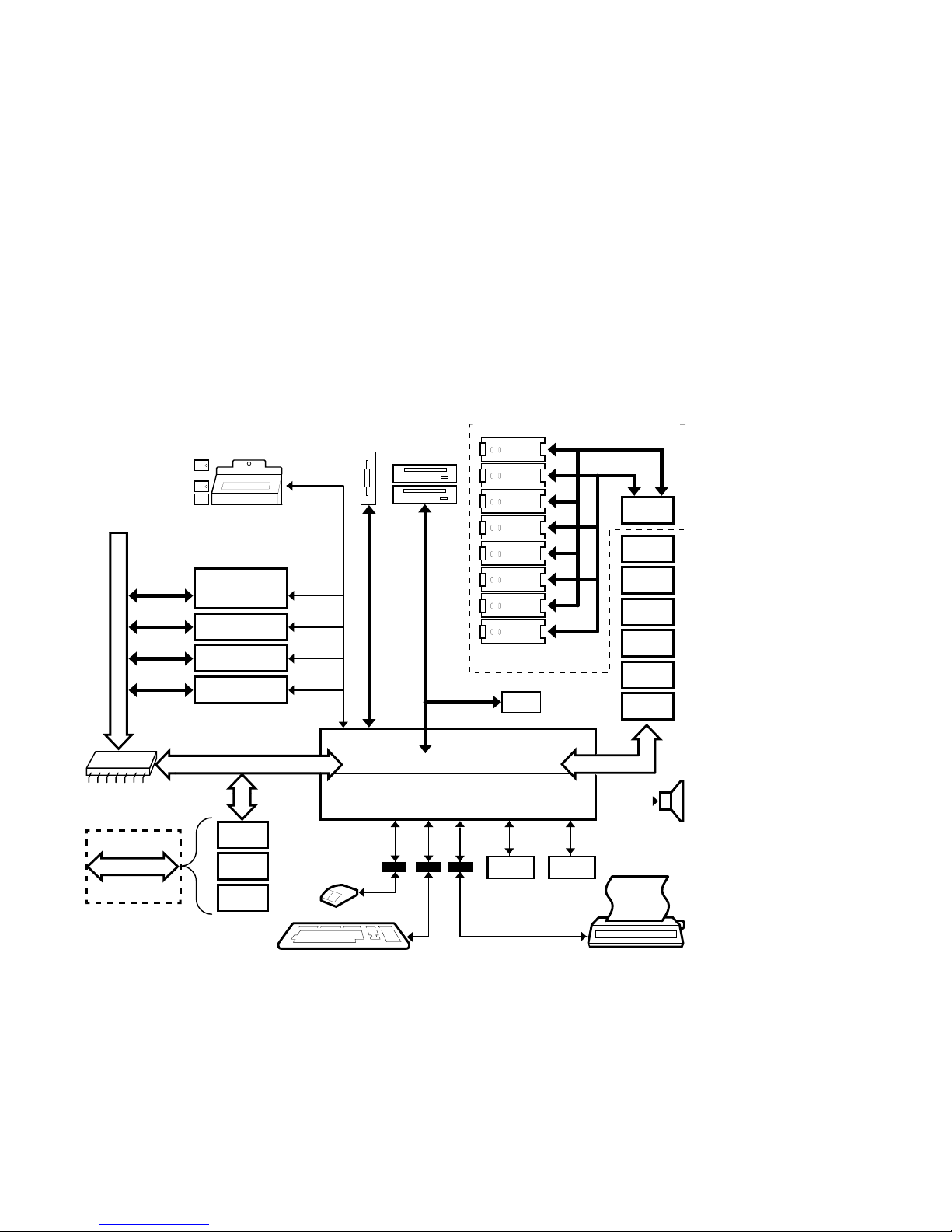
Architecture
Figure 1–1 illustrates the server system architecture.
Figure 1–1 System Architecture
Operator Control Panel
System Bus
128-bit
PCI Bridge
Slot 1
Slot 2
Slot 3
Slot 4
Expansion I/O
or MEM 1
MEM 0
CPU 0
CPU 1
PCI Bus 32-bit
Serial
Control
Bus
I/O Backplane
Option
SCSI
SCSI
SCSI
EISA 1
EISA 2
EISA 3
EISA 4
EISA 5
EISA 6
EISA 7
EISA Bus
PCI 0
Network
Option
PCI 1
PCI 2
COM1
Parallel
Serial
Serial
COM2
Speaker
MA00060
Basic Operation 1–5
Environmental and Power Requirements
Environmental and Power Requirements
In This Section
System
Dimensions
This section covers the following information:
• System Dimensions
• Environmental Specifications
• Power Requirements
• Power Cord Numbers
• Moving the System
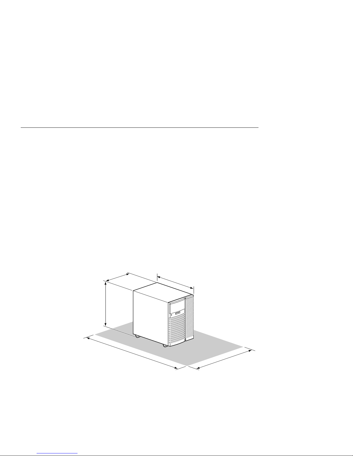
Figure 1–2 shows the system dimensions and the clearance area
necessary for service access.
Figure 1–2 System Dimensions and Service Area
43 cm
(17 in)
60.5 cm
(23.8 in)
65 cm
(25.6 in)
175 cm
(69 in)
1–6 Basic Operation
125 cm
(50 in)
MA00062

Environmental and Power Requirements
Environmental
Specifications
Table 1–2 describes the environmental specifications for your
system.
Table 1–2 Environmental Specifications
Specification Measurement
Operating temperature 10-35° C (50-95° F)
Relative humidity (noncondensing) 20-80%
Maximum heat dissipation
Single power supply 2390 Btu/hr
Dual power supply 4097 Btu/hr
Minimum operating clearance
Front 75 cm (29.5 in)
Rear 15 cm (5.9 in)
Maximum operating altitude 2000 m (6562 ft)
Maximum current rating
Single power supply 8.0/4.0 A
Dual power supply 4.6/2.2 A
Operating voltage range (single
phase)
100–120/
220–240 VAC
Operating frequency range 50 Hz to 60 Hz
Power cord length 190 cm (75 in)
Basic Operation 1–7
Environmental and Power Requirements
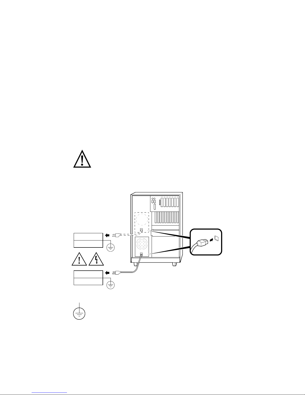
Power
Requirements
Depending on what you ordered, your system has either one or
two power supplies. Figure 1–3 shows the power requirements
for each power supply.
Voltage selection is not required. This equipment automatically
senses the voltage and adjusts accordingly.
Warning: Plug this equipment into a properly
grounded power receptacle.
Figure 1–3 Power Requirements
115 V (15.0 A)
220 V (6.0 A)
115 V (15.0 A)
220 V (6.0 A)
Properly grounded power receptacle
1–8 Basic Operation
MA00015A

Environmental and Power Requirements
Power Cords
Power cords for your Digital system are country specific.
Table 1–3 lists the correct power cord order numbers for various
countries.
• Use the power cord BN number to identify the power cord.
• The Digital Number is used by Digital service
representatives.
Note
One power cord is required for each power supply in
your system. To order, call 1-800-DIGITAL (U.S.A. and
Canada) or your authorized Digital distributor.
Table 1–3 Power Cord Order Numbers
Country Power Cord BN Number Digital Number
U.S., Japan, Canada BN09A-1K 17-00083-09
Australia, New Zealand BN019H-2E 17-00198-14
Central Europe (Aus, Bel,
Fra, Ger, Fin, Hol, Nor,
BN19C-2E 17-00199-21
right-angle wall plug
Swe, Por, Spa)
U.K., Ireland BN19A-2E 17-00209-15
Switzerland BN19E-2E 17-00210-13
Denmark BN19K-2E 17-00310-08
Italy BN19M-2E 17-00364-18
India, South Africa BN19S-2E 17-00456-16
Israel BN18L-2E 17-00457-16
Basic Operation 1–9

Environmental and Power Requirements
Moving the
System
Repositioning
the System
If you need to move your system to a new environment, be sure
you are familiar with the environmental specifications and power
cord requirements.
Caution
Only qualified service persons should install the system.
Qualified service persons need not be Digital service
representatives, but they should have the technical
training and experience necessary:
• To be aware of physical hazards to which they are
exposed in performing a task.
• To take measures to minimize danger to themselves
and other persons.
To reposition the system within the same environment, raise the
system leveler feet (shown in Figure 1–4) so that they no longer
touch the floor, and push the system to the new destination.
When you have positioned the system, lower the leveler feet to
the floor so that they hold the system stationary.
If you must ship your system to a new location, carefully
repackage it so that it can withstand the normal bumps or
shocks associated with moving.
Figure 1–4 Leveler Feet
1–10 Basic Operation
MA00063
Environmental and Power Requirements
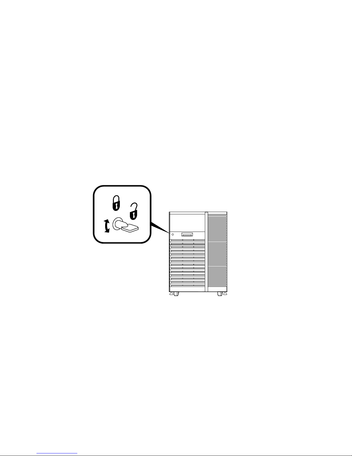
Opening the
System Door
The key used to lock and unlock the front door arrived with
your system shipment, packaged with the system installation
card. The key lock on the front door of the system is shown in
Figure 1–5.
Figure 1–5 System Keys
MA00087
Basic Operation 1–11

Turning the System On
Turning the System On
Overview
Turn on the system in the sequence shown below and described
in the following sections:
1. Check System Settings
2. Power Up the System
3. Check Power-Up Display
4. Perform Pre-Boot Tasks
5. Boot Operating System
1–12 Basic Operation
 Loading...