

Page 1
85XX Series Network DVR User Manual……………………………………………………………………….V1.0
- 1 -
85XX Series Network DVR User Manual
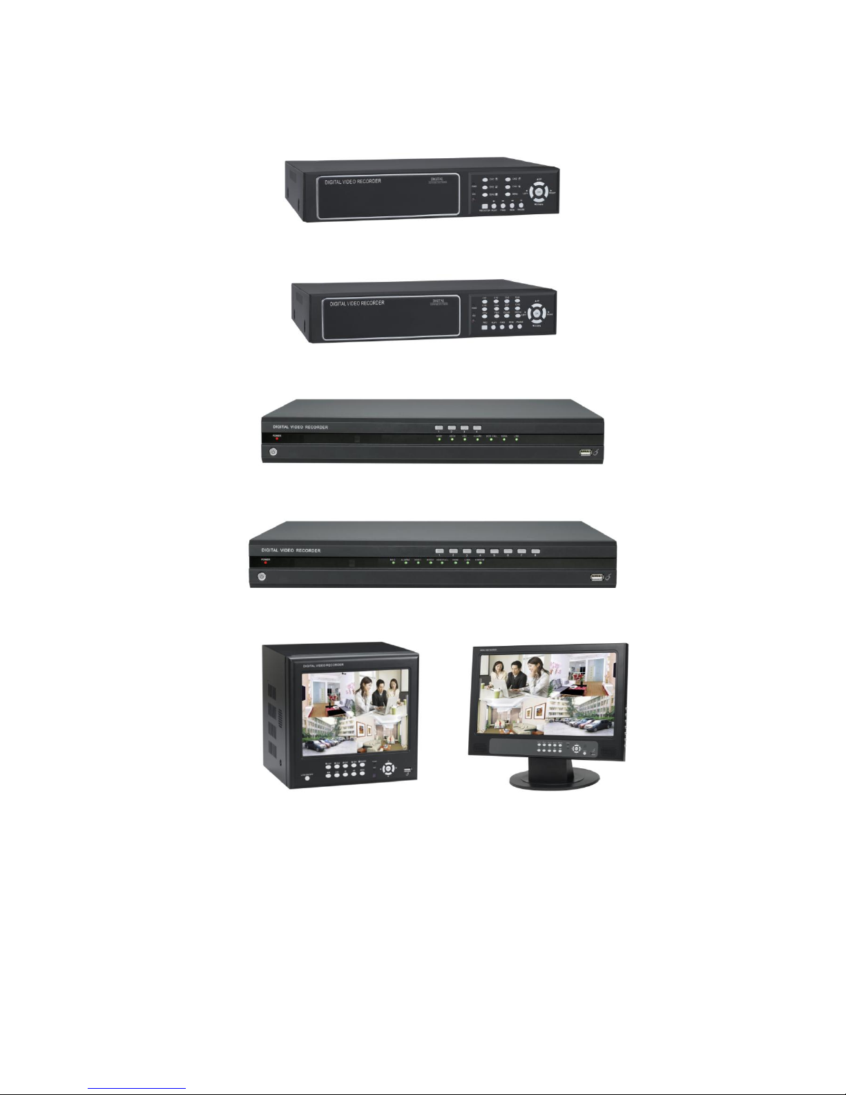
8504/8504P
8508
H8504P/AH8504P
H8508/AH8508
8504FP/8508F/A8504FP 8504CP/8508C/A8504CP
/F8504FP/F8508F/A8508F F8504CP/F8508C/A8508C
PLEASE READ CAREFULLY AND SAVE
This manual contains important information about this product's operation. If you are installing this product for
others, you must leave this manual for a copy with the end user.
The DVR color included in the packing may be different from the user manual or packing.The picture is only for
reference
Page 2
85XX Series Network DVR User Manual……………………………………………………………………….V1.0
- 2 -
Page 3

85XX Series Network DVR User Manual……………………………………………………………………….V1.0
- 3 -
CONTENT
CHAPTER 1 INTRODUCTION ............................................................................................... 4
1.1 MAIN FEATURE ............................................................................................................................................................. 4
1.2 PRODUCT FEATURES ...................................................................................................................................................... 4
1.2.1 Parameter .............................................................................................................................................................. 4
1.2.2 Working Environment ........................................................................................................................................... 5
1.2.3 Device Environment.............................................................................................................................................. 5
CHAPTER 2 DEVICE OPERATION MANUAL .................................................................... 6
2.1 CONTROL INSTRUCTION ................................................................................................................................................. 6
2.1.1 Remote Controller Instruction ................................................................................................................................ 6
2.1.2 Mouse Operation.................................................................................................................................................... 7
2.1.3 MENU CONFIGURATION ........................................................................................................................................... 7
2.2 SYSTEM OPERATION ...................................................................................................................................................... 8
2.2.1 START-UP ............................................................................................................................................................ 8
2.2.2 SYSTEM LOGIN .................................................................................................................................................. 8
2.2.3 GUI OPERATION ................................................................................................................................................. 9
2.3 TOUCH-SCREEN MANUAL ............................................................................................................................................. 27
CHAPTER 3 IE REMOTE ACCESS ...................................................................................... 30
3.1 FEATURES ................................................................................................................................................................... 30
3.2 LOGIN ......................................................................................................................................................................... 30
3.3 IE BROWSER INTERFACE .............................................................................................................................................. 31
3.3.1 LIVE ................................................................................................................................................................... 32
3.3.2 Playback .............................................................................................................................................................. 33
3.3.3 Setup ................................................................................................................................................................... 35
4 VCA SOFTWARE OPERATION MANUAL ...................................................................... 39
4.1 INSTALLATION ............................................................................................................................................................. 39
4.2 LOGIN ................................................................................................ ....................................................................... 42
4. 3SETUP ......................................................................................................................................................................... 45
4.4 VCA SETTING.............................................................................................................................................................. 65
5 DVR INSTALLATION GUIDELINE .................................................................................. 97
5.1 FRONT PANEL ................................................................ .............................................................................................. 97
5.1.1 The Definition of Bottoms and Connectors on Front Panel .................................................................................... 97
5.1.2 The definition of buttons and connectors on rear panel ....................................................................................... 99
5.2 DVR HDD INSTALLATION DEMONSTRATION ........................................................................................................... 104
5.2.1 HDD Installation ................................................................................................................................ .............. 104
CHAPTER 6 DEVICE PART................................................................ ................................ 105
6.1 CHECK DEVICE PART ................................................................................................................................................. 105
CHAPTER 7 FAQ .................................................................................................................. 106
GUARANTEE ........................................................................................................................ 110
Page 4

85XX Series Network DVR User Manual……………………………………………………………………….V1.0
- 4 -
Chapter 1 INTRODUCTION
1.1 Main Feature
85XX series DVR is 4CH D1 and 8CH CIF resolution digital video recorder. Both of them have local
recording, playback, support treble code remote network surveillance, data backup, parameter setting, motion
detection, I/O alarm setting, PTZ and USB mouse.
1.2 Product features
Advanced Linux;
H.264 compression, support D1;
USB or IE to upgrade software;
PTZ and network function;
Support Multi-Language firmware;
Support mobile surveillance;
Support network center management system(CMS);
Applied in large surveillance area such as supermarket, gas station, factory etc.
1.2.1 Parameter
Content
Item
Instruction
System
Language
Multi-language
OSD
Friendly GUI OSD menu
Password
With six user groups for user and administractor
Video
Video Input
4/8CH BNC Input, with 1.0V p-p, 75Ω
Video Output
1CH BNC Output, with 1.0V p-p,75Ω
Video Display
4CH:1/4 channels display;
8CH: 1/4/9 channels display
Video System
PAL: 25fps/CH, CCIR625 line, 50Hz
NTSC: 30fps/CH, CCIR525 line, 60Hz
Audio
Audio Input
4/8CH RCA audio input, with 600Ω
Audio Output
1CH RCA audio output, with 600Ω
Output voltage
Linear voltage
Record mode
Support record with Video and Audio simultaneously
Audio
Compression
ADPCM
Video process and
save
Video
Compression
H.264
Resolution
CIF/HD1/D1
Video Standard
ISO14496-10
Audio Standard
ADPCM
Page 5
85XX Series Network DVR User Manual……………………………………………………………………….V1.0
- 5 -
1.2.2 Working Environment
Item
Parameter
Instruction
Host Input Voltage
DC 12V
Video Input Resistance
75Ω
The resistance of each input channel is 75Ω.
Video Output
1Vp-p
Each channel for output is Vp-p with CVBS analog signal.
Working Temperature
-10----50℃
It’s the environment temperature around the DVR.
I/O Alarm Port
0—2V
It’s for low voltage alarm
5V-30V
It’s for high voltage alarm
RS485 Port
Connect PTZ through Pelco-D, Pelco-P protocol.
1.2.3 Device Environment
In order to make the DVR in long running and safe using, before install the DVR, please consider the following
Video bit rate
CIF: 384,512,768 Kbps
HD1: 512,768,1024 Kbps
D1:896,1024,1280Kbps
Audio bit rate
32KB/s
Data save mode
Support SATA HDD
Alarm
Alarm Input
4CH/8CH Alarm input
Alarm Output
1CH Alarm output
Communication port
Serial port
Support 1 RS485 port
Network port
NET port, 10M/100M adapt network port
USB
Mouse
USB2.0
USB Driver
USB2.0
VGA
VGA Output
Support 800×600,1024×768,1280×1024,1366×768,1440×900
Software
IE remote access
Install ActiveX for video preview, record download and configuration
of DVR
TFT Monitor
8504FP/8508F/A8504FP/A8508F/F8504FP/F8508F(8″Digital TFT)
8504CP/8508C/F8504CP/F8508C/A8504CP/A8508C(15.6″Digital
TFT)
Upgrade
Support USB driver or IE browser upgrade
Other
Power Adapters
Input Voltage
AC:110~240V
Power
6W (Without HDD and additional device)
Temperature
-10----50℃
Page 6
85XX Series Network DVR User Manual……………………………………………………………………….V1.0
- 6 -
attention:
1. When install and operate the DVR, apply with the electrical standard request and connection requirement.
2. Make sure the power supply is connected to ground.
3. Do not touch the power supply adaptor and DVR in wet.
4. Do not drop the liquid onto the DVR device in order to avoid short circuit inside.
5. Do not lay on other heavy subjects to DVR.
6. Clear the DVR with soft cloth, and do not use chemical solvent.
7. If the DVR power supply and connection is correct, and the DVR is not able to start, it maybe the problem of
voltage, make sure the voltage is normal.
8. If the DVR will be rest in long time, it’s better to cut off the power supply and plug off the adaptor.
Chapter 2 Device operation manual
2.1 Control Instruction
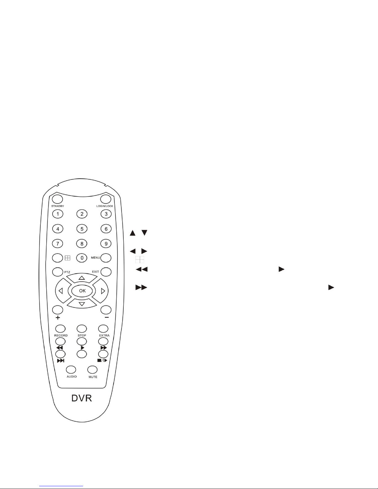
2.1.1 Remote Controller Instruction
Handheld IR Controller Key Functions:
【0-9】keys: During setup, number keys are used to input values. For
viewing channels 1, 2, 3 and 4, use 1, 2, 3 and 4 on numeric keypad
respectively.
【+】,【-】keys: During setup, plus and minus are used to select next or
previous values.
, : Up, Down directional keys: Move selection up and down in setup
menu.
, : Left, Right directional keys: Move cursors left or right in setup menu.
【 】: Switch 4 Channels;
【 】: Fast forward the video while playback. press 【 】to return to normal
speed;
【 】: Reverse the video while playback, press REW to switch, press【 】
to return to normal speed;
【STANDBY】: Reset the DVR to Power on off mode. (Standby and start up);
【LOGIN/LOCK】: If the security is enabled in the setup, use LOGIN/LOCK
key to enter the user setup. It is important to remember the password due to
without restoration function. Log in( to enter into “User ID select” and
“Password” input interface)and lock functions(To exit setup and operation).
【MENU】: Press OSD for main menu;
【PTZ】: PTZ control,press this key to enter into PTZ control interface when
at single live view;
【EXIT】: Exit to the preview or return to the last menu;
【RECORD】: Start manual record
【STOP】: Stop manual record
【ASISTANT】For future use
Page 7

85XX Series Network DVR User Manual……………………………………………………………………….V1.0
- 7 -
2.1.2 Mouse Operation
You can use mouse to make operation of the menu besides IR remote controller. (The operation is the same as
PC Windows).Please inserts the mouse into USB Port.
Click right
key
Enter into main menu: Click the right key on the live view.
Click left key
Click the left key to enter into the setting interface.
Click the left key to zoom in the window on the live view and playback video. Double
click the left key can exit to the live view and playback multi-window interface.
1. Volume adjustment, color adjustment, PTZ setting and VGA border operation. It
is for setting the single channel, PTZ control and color adjustment. If it is
multi-window, please use the left key to select the single window.
2. The remark when click the left key, color adjustment, VGA border is as follow:
a. There are and for buttons the PTZ setting to adjust parameter, click
it can adjust the setting for PTZ.
b. There is a sticker to show the volume on the volume adjustment interface.
Move the mouse to the corresponding position and click the left key. The right
side of sticker will show the volume, click “x” to exit.
c. Color adjustment can refer to the volume adjustment interface operation.
When there are many options in the option frame, click left key to see down-pull
menu.
To click the left key on the playback interface can make >> means forward, <<
means raw, >>I means Slow play, I> means Pause frame play,> means Play, X
means exit.
Click left key
1. In the input frame, click the left key can activate the keyboard. The number,
symbol, English can be input by clicking the mouse.
2. Pinyin also can be input by the soft keyboard when enter Chinese, the method is
the same as remote control. You can use the left/right key to turn over the page
when check on Pinyin/Chinese word.
3. When input number, click the right key, the number soft keyboard will bob up first,
and then use the left key to select the corresponding numerical value. Also click the
left key to exit the number keyboard.
Mouse move
1. Press the left key to move the mouse can adjust the parameter on the volume,
color, VGA border interface. And the corresponding parameter will be display at the
same time.
2. In the Motion Detection setting interface, you can use the left key to drag the
frame to set the motion detection area.
Scroll-Wheel
Switch VGA and BGC
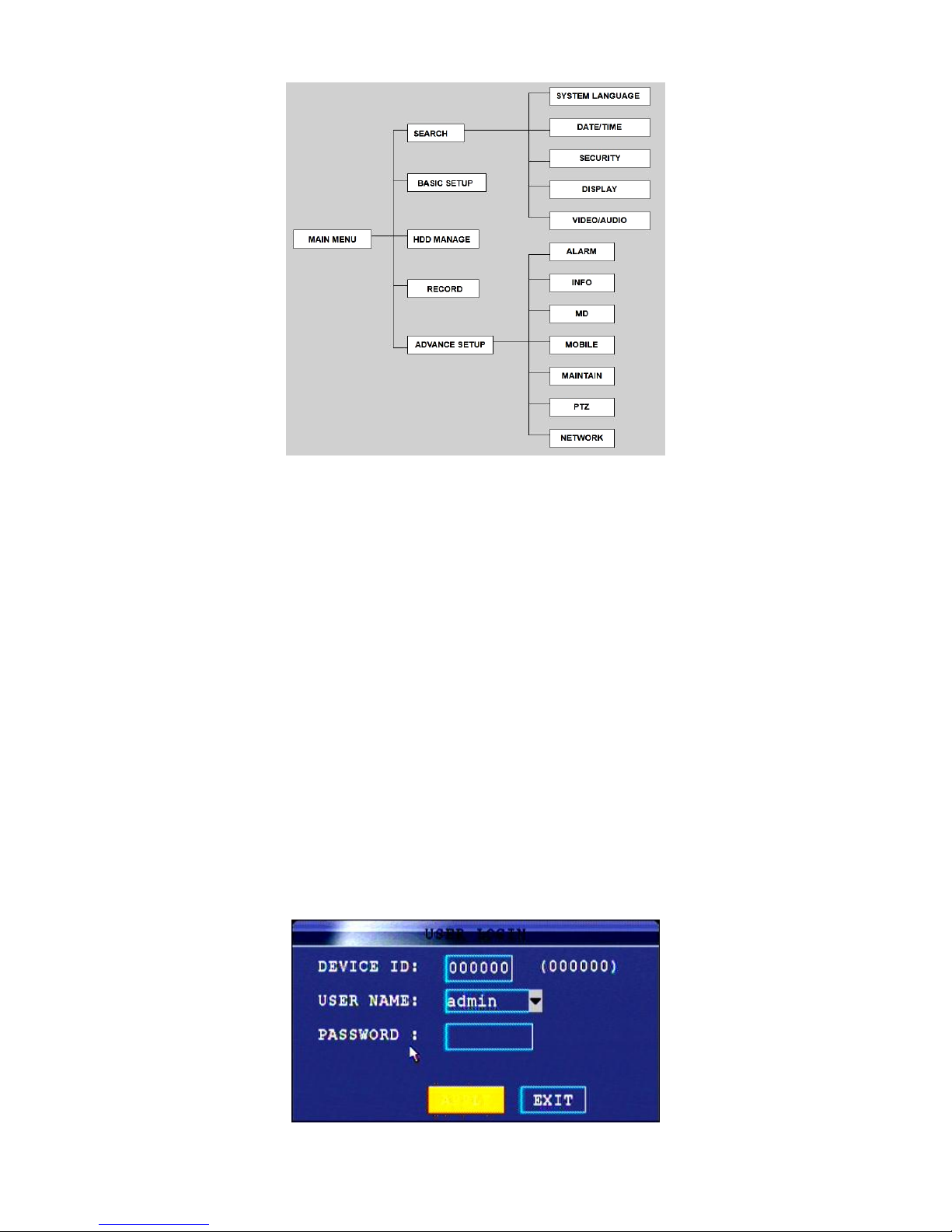
2.1.3 Menu Configuration
You can control the DVR by a lot of menu operation. This tree will show you the menu structure and it will be in
details in the following chapters.
Page 8
85XX Series Network DVR User Manual……………………………………………………………………….V1.0
- 8 -
2.2 System Operation
2.2.1 START-UP
Connect the power adapter to DVR. When start up the DVR, 【POWER】LED will be on and 4 images will be
display on the screen. If it has setup ignition recording or time recording, the system will record automatically
and the corresponding LED will be on, and the system work normally.
Remark:
1. If there is no HDD in device, or the device didn’t read the HDD, or the HDD didn’t be formatted it will display
an 【H】 in the video preview interface.
2. You must format the HDD in the DVR before first using. The steps as follows: menu > HDD management >
format. After formatting, the system will restart.
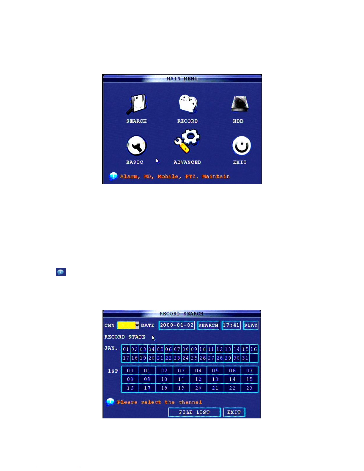
2.2.2 SYSTEM LOGIN
Remark: default device ID is: 00000, and there is no password. In order to keep safe, please modify the user
password and change the device ID in the base setup. You can setup user and admin password, Admin has all
authorities while user has limited authorities of viewing image, searching and play backing video. When you
input a password, the system will automatically match and offer different password with different authorities.
When DVR started, click right key by mouse. If you open a password, it will enter into user login interface. The
picture is as follows:
Page 9
85XX Series Network DVR User Manual……………………………………………………………………….V1.0
- 9 -
Device ID: You just need to enter the device ID as the right frame.
Password: enter the admin password or user password.
2.2.3 GUI OPERATION
The main menu include “SEARCH”,”RECORD”,”HDD”,”BASIC”,“ADVANCE”, and “Exit”.
Remark: You must press “APPLY” to make the setting for submenu valid. It will be no use when exit directly.
There is a special feature of this DVR: when you move the mouse somewhere, the explanation information will
be showed automatically.
1. SEARCH: Search the record files, playback and backup the data;
2. RECORD: To set the record parameter;
3. HDD: To show the HDD running status and manage the HDD;
4. BASIC: To set Date and Time, Language, Video/Audio, Standard and User group;
5. ADVANCED: To set System, Alarm, PTZ, Network and Maintenance;
6. EXIT: To exit the main menu;
7. To show the information of instruction.
2.2.3.1 Search
2.2.3.1.1 Search record
Select 【SEARCH】 to enter the search setting interface.
Input the date then click “SEARCH”, the record status will be shown as bellows,
Page 10

85XX Series Network DVR User Manual……………………………………………………………………….V1.0
- 10 -
The first two lines is for Month, and the below three lines is for Day. The green color block is general record;
the red color block is alarm record.
Double click the day then system will playback the record for whole day. If click “FILE LIST”, the system will
show the record file list.
TYPE: The default is show all the channel;
SEARCH: To classify the record file through channel or time;
FIRST: To skip the file list to the first page;
PRE: To turn to the previous page;
NEXT: To turn to the next page;
LAST: To skip the file list to the last page;
ALL: To select all the record files in the list;
OTHER: To select all the record files except the current page;
BACKUP: To backup the selected file;
EXIT: To exit the file record interface.
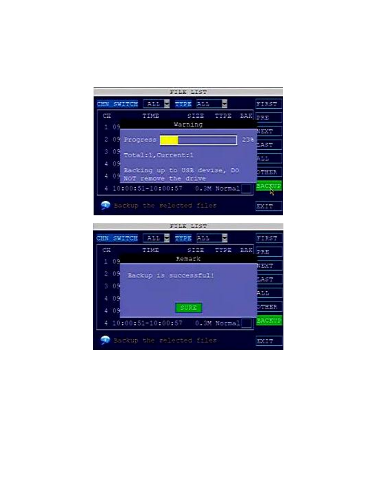
2.2.3.1.2 Backup
Before backup, please prepare the USB Driver, which is better with capacity between 256MB to 32GB.
Backup steps:
A. Insert the USB Driver to the USB port on back panel, please make attention do not insert the port the
Page 11
85XX Series Network DVR User Manual……………………………………………………………………….V1.0
- 11 -
USB mouse port;
B. Loin system and enter SEARCH menu, click FILE LIST to show the record files;
C. Select the record file you want to backup;
D. Click BACKUP to backup the data.
Please make sure the power supply is stable during backup, and make sure do not plug off the USB during
backup.
Remarks: If the free space of USB driver is not enough to save the backup data, the system will remind and
show the space is not enough.
2.2.3.2 Record
2.2.3.2.1 Record parameter
Select 【RECORD】 to enter the record setting interface.
Page 12

85XX Series Network DVR User Manual……………………………………………………………………….V1.0
- 12 -
Switch: Set the channel in ON or OFF status, that is to set the channel is open or close status.
Resolution: For 9504 DVR, there’re D1, HD1, CIF options;
For 9508 DVR, in CH1 and CH2, there’re D1, HD1, CIF options; and other channel only with HD1, CIF options.
Bitrate: There’re three options to be selected, L, M, H.
L->Low, the bit rate is as: CIF: 384 Kbps; HD1: 512 Kbps; D1: 896 Kbps;
M->Middle, the bit rate is as: CIF: 512 Kbps; HD1: 768 Kbps; D1: 1024 Kbps;
H->High, the bit rate is as: CIF: 768 Kbps; HD1: 1024 Kbps; D1: 1280 Kbps;
Frame Rate: The frame rate of image could be set, but the total frame rate is 200fps/PAL, 240fps/NTSC for
4CH, 400fps/PAL, 480fps/NTSC for 8CH. And the maximum frame rate for each channel is 25fps/PAL,
30fps/NTSC.
Note: 1 D1=4CIF, 1 HD1=2CIF.
Audio: To set the audio ON or OFF.
Rec. Mode:
POWER UP: the system will begin to record when DVR is start.
TIMER RECORD: the system will record as schedule.
Rec. Size: the system will process the record every 15minutes, 30minutes, 45minutes, and 60minutes.
Mask Area: to set the camera mask area in live demo.
After set the parameter, click APPLY to reserve and exit.
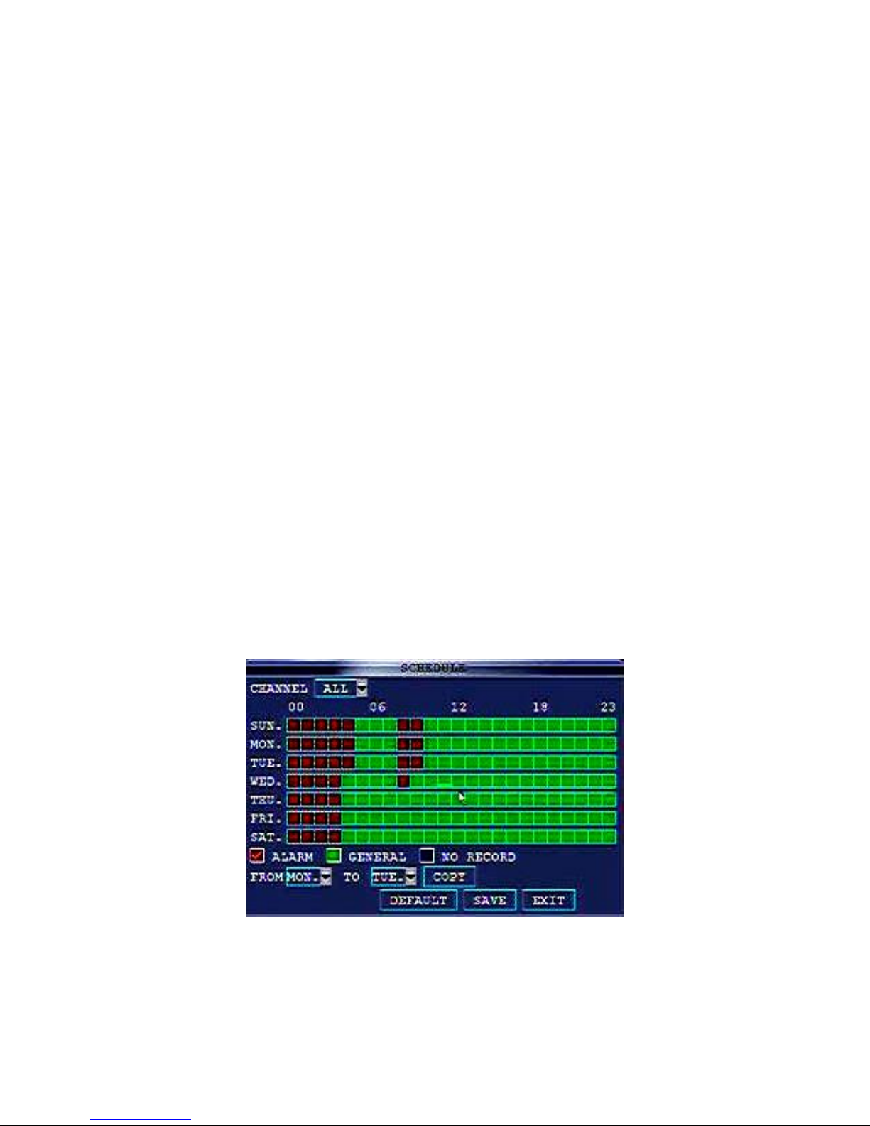
2.2.3.2.2 SCHEDULE RECORD
If select the record mode in TIME RECORD, the system will record as schedule. The user could set the time
duration to record.
Page 13
85XX Series Network DVR User Manual……………………………………………………………………….V1.0
- 13 -
The time table shows one week and 0-23hrs in one day. Users could set the time duration as alarm record
(Red), normal record (Green), and no recording (Blue).
Schedule record steps:
A. Select the TIMER RECORD in RECORD menu.
B. Select the channel for schedule record.
C. Select the record mode, like Alarm, Normal record in Red or Green color.
D. Click the blue block in red or green color which to set the time duration you want to record in one day.
E. Select the day in “COPY TO” to click “COPY” button to copy the schedule record setting to other days in one
week.
F. Click APPLY to save the setting and exit.
For example, you want the system record from Monday to Friday and from 9:00 to 17:00 with all the channels,
and you also hope to record the alarm/MD record from 17:00 to 9:00. But do not record on Saturday and
Sunday.
Notice: In default settings, one week includes 7days, recording in succession for 24hrs.
Record time settings:
A. Select the TIMER RECORD in RECORD menu.
B. Select channels for “all”
C. Click the blue box (not record) under the time table, it will display “√”sign.
D. Move the cursor to 『SUN』, click the entire box from 00~23hrs, the box turned blue.
E. In “COPY TO” selection box choose Sunday, and in “set to” selection box choose Saturday, then click
“COPY” button.
F. Click the box in red (alarm recording) under the time table.
G. Move the cursor to 『MON』, click the entire box from 00~23hrs, the box turned red.
H. In “COPY TO” selection box choose Monday, and in “set to” selection box choose
Tuesday, then click “COPY” button. Keep the same copy to 『Wed』『 Thu』『 Fri』, the settings will display as
below:
I. Click APPLY to save the setting and exit
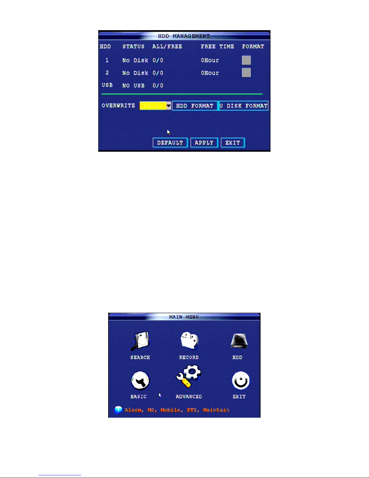
2.2.3.3 HDD Management
Select 【HDD】 to enter the HDD management setting interface. It will display the system embedded HDD
basic information, and can format the HDD and U disk.
Page 14
85XX Series Network DVR User Manual……………………………………………………………………….V1.0
- 14 -
HDD STATUS:
SIZE: shows HDD total capacity.
FREE SPACE: show the free space of HDD.
AVAILABLE TIME: show the remaining recording time depends on the video packing time you set.
OVERWRITE: there’re two options ENABLE or DISABLE.
If in ENABLE, and if the HDD capacity is full, the system will overwrite the previous record automatically.
If in DIABLE: and if the HDD capacity is full, system will stop recording and the “FULL” LED light on the front
panel will indicate on as well.
USB STATUS:
SIZE: show the USB driver total capacity.
FREE SPACE: show the free space of USB driver.
HDD FORMAT: to format the HDD. Notice: HDD format will delete all the video data. And the data will
NOT be recovered.
USB FORMAT: to format the USB driver. Before using USB driver to backup video data and upgrade the
firmware, we suggest format the USB first.
2.2.3.4 BASIC SETUP
Select 【BASIC】 to enter the system basic information setting interface. Basic setup includes language,
date/time, password, display, and video/audio and exit six options.
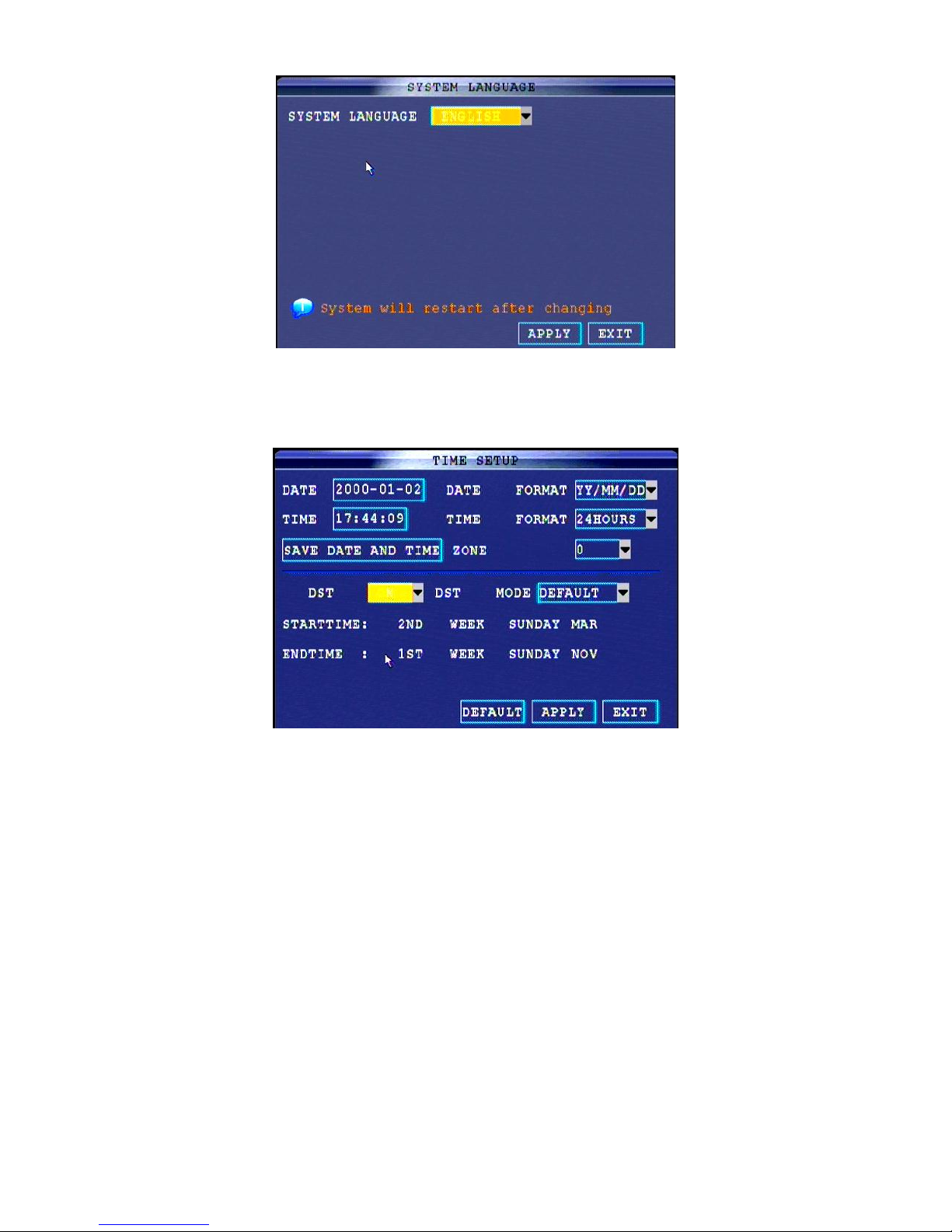
2.2.3.4.1 Language
Page 15
85XX Series Network DVR User Manual……………………………………………………………………….V1.0
- 15 -
SYSTEM LANGUAGE: Select the language and click APPLY, then system will restart.
Now the system is available for multiple language firmwares, such as English, Russian, Spanish, French, Thai
language etc.
2.2.3.4.2 DATE/TIME
Date and Time setup:
A. Input the date and time, and select the date format in TIME SETUP. Make sure the system date and time is
the same with computer when need to remote access from outside internet.
DATE: Press【Enter】or 【+】/【-】or press number key to choose the date.
DATE FORMAT: Press ENTER to switch between the date patterns, there are YY-MM-DD and MM/DD/YY two
options.
TIME: Press【Enter】or 【+】/【-】or press number key to choose the date.
TIME FORMAT: Press ENTER to switch between the date patterns, there are 12 HOURS and 24 HOURS two
options.
B. Click “SAVE DATE AND TIME” to reserve the date and time setting.
Zone: the time zone which the DVR device is in.
C. Click APPLY to save the setting, then the date and time setup will be reserve.
DST (Daylight Saving Time)
DST setup:
A. Select ON to open the DST。
B. There is User-defined and default mode to choose:
·User-defined:Skip to Step4
Page 16

85XX Series Network DVR User Manual……………………………………………………………………….V1.0
- 16 -
·Default:In default, DST is from the 2nd Sun of March to 2nd Sun to November. (Skip to Step3)
C. Select default, click “enter” to setup.
D. Select user-defined mode, choose the corresponding week and month is OK.
E. Click “APPLY” to save and exit.
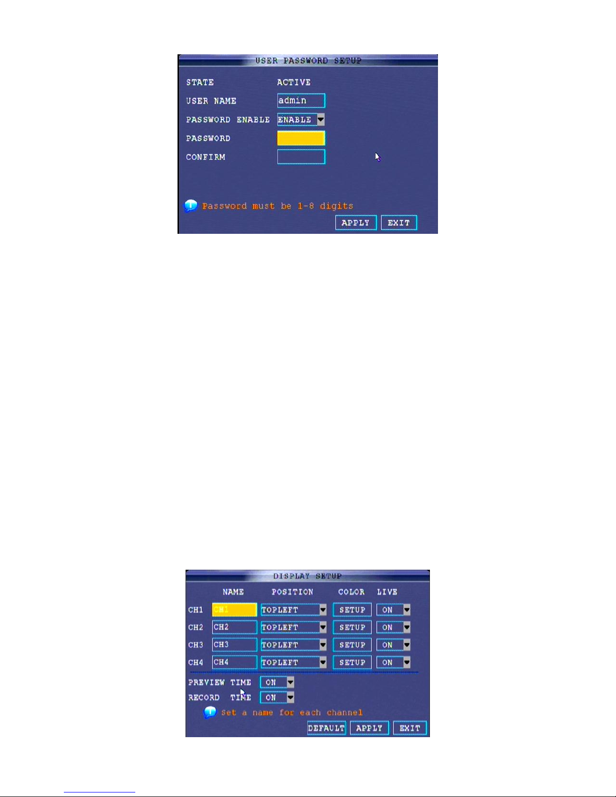
2.2.3.4.3 PASSWORD
When user starts the system in first time, system will identify with “000000” as the device serial number to login.
There are 2 users groups which are one admin group and 4 users group, and one device serial number.
Administrator: Have all the rights of system operation; click CONFIG to input the password.
User: only have the right to surveillance view, record searching, video playback and other restricted right. Click
CONFIG to input the password.
Remark: We strongly suggest you enable your system password for admin password and user password with
6 numeral numbers.
Notice: In default setting, the system is without password. Users can access any functions without any
password.
Page 17
85XX Series Network DVR User Manual……………………………………………………………………….V1.0
- 17 -
User can change the device serial number, admin and user password in the password setting interface.
Open the Password interface:
A. right clicks anywhere to open the sub-menu, and select the main menu.
B. Select the basic setting in the interface。
C. Select the password to enter the user management interface.
Change the device serial number and password:
A. Click serial number and key into 6 numeral numbers (by mouse). For example: 000010.
B. Select “ON” to enable using password.。
C. Click user password and key into 6 numeral numbers (by mouse). In the corresponding field “enter again” to
save and confirm.
D. Click Admin password and key into 6 numeral number (by mouse). In the corresponding field “enter again”
to save and confirm.。
Notice: User password should not be the same as the one for admin.
E. Click “APPLY” to save and exit.
User can access the system menu by new password. And can also access the system through internet with
the admin and user password.
Delete network password: Delete the network password and click enter to save. The system will recover to IE
browser password.
2.2.3.4.4 DISPLAY
Through display menu to change the channel name, display/hide the view and playback time and date, and
enable/disable preview channel.
Page 18
85XX Series Network DVR User Manual……………………………………………………………………….V1.0
- 18 -
NAME: input the new name through mouse or remote control.
POSITION: locate the channel name in live window; there are TOPLEFT, BOTTOMLEFT, TOPRIGHT,
BOTTOMRIGHT and OFF. Select OFF, the name will not be shown on the window.
COLOR: adjusting the chrome, brightness, contrast and saturation.
LIVE: there are ON/OFF option to display/hide the playback time and date.
PREVIEW TIME: there are ON/OFF options to display/hide the live time and date.
RECORD TIME: there are ON/OFF options to display/hide the playback time and date.
After set the parameter, click APPLY to save and exit.
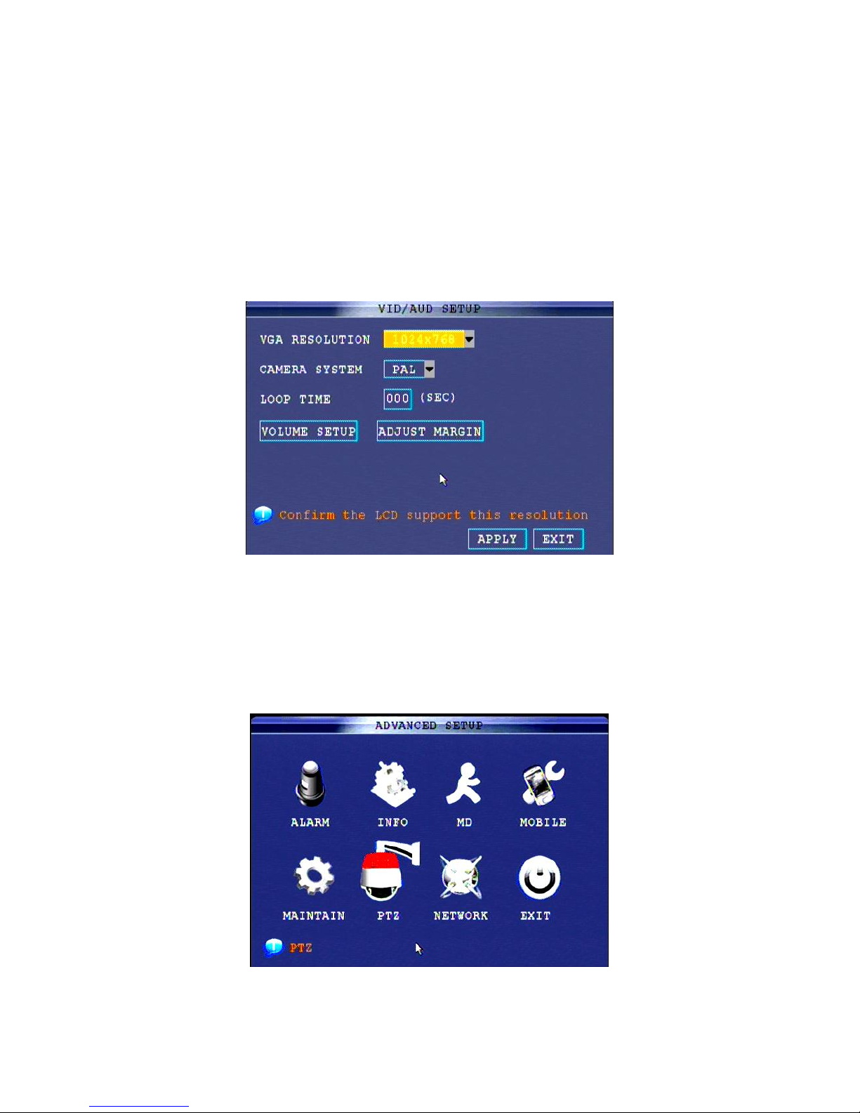
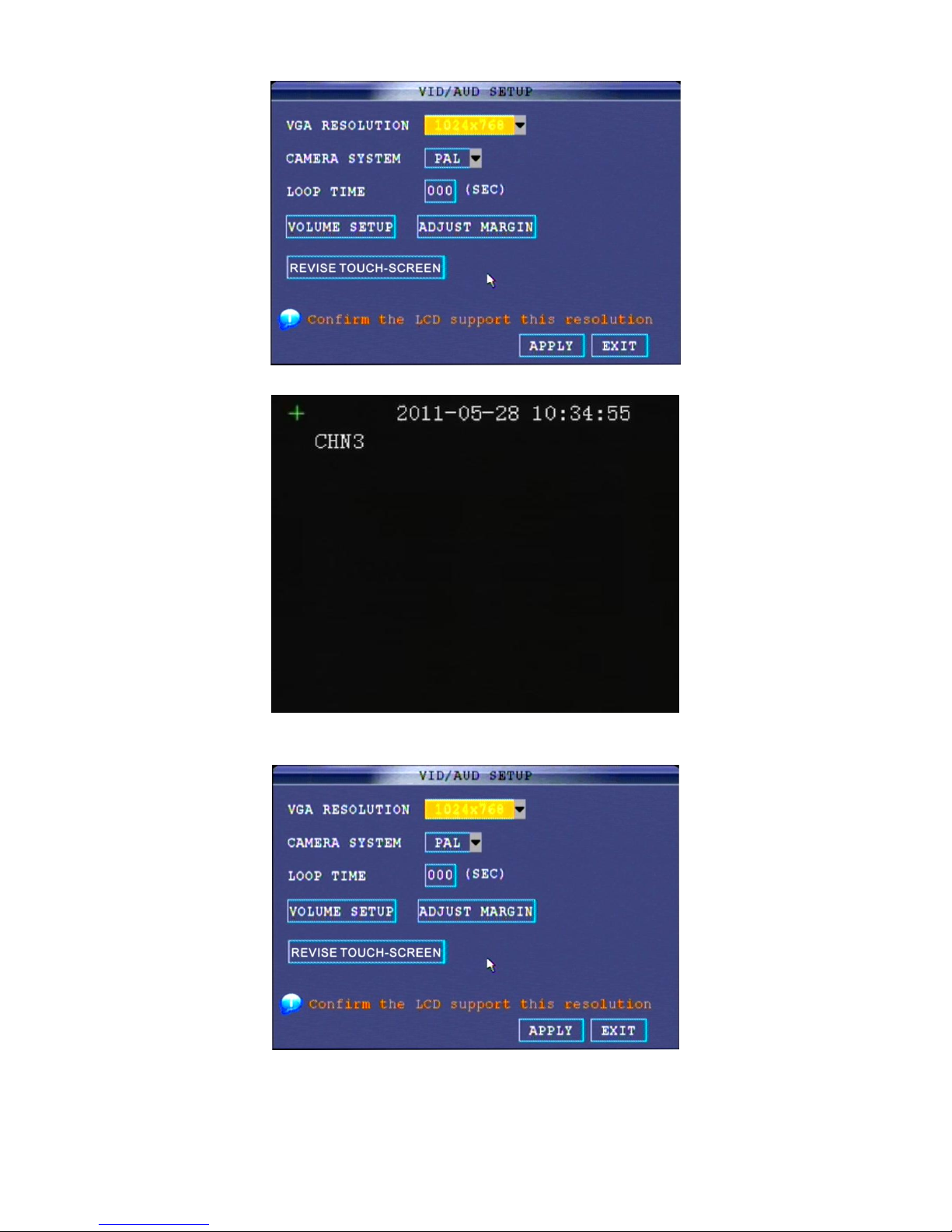
2.2.3.4.5 VIDEO/AUDIO
Video/audio setup can set the resolution and camera system standard.
VGA resolution: there 800×600, 1024×768, 1280×1024, 1366×768, 1440×900 five options.
Camera system: there are NTSC and PAL systems standard.
Loop Time: to set the time to rotate the window when there’s only one live window.
Volume Setup: to setup the audio volume.
2.2.3.5 ADVANCED
Advance menu includes alarm, system information, motion detection, mobile, system maintenance, PTZ and
network setting.
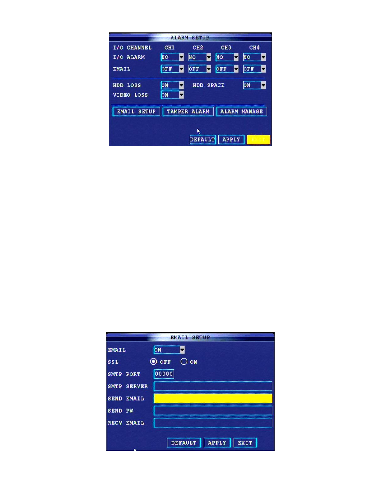
2.2.3.5.1 ALARM
Page 19
85XX Series Network DVR User Manual……………………………………………………………………….V1.0
- 19 -
I/O ALARM: show each channel alarm status, that is, when an alarm triggered, it will activate the
corresponding channel to start alarm recording.
NO: indicate alarm is Normal Open; it will be ON when have alarm
NC: indicate alarm is Normal Close; it will be OFF when there is a alarm
HDD LOSS: if ON, means it will trigger alarm if there is no HDD, and it will display【H】on the bottom of each
channel in the live window. If OFF, there will be not alarm, but still will show 【H】in live window.
HDD SPACE: if ON, if the space is less than 500M, there is remind window in live view: No enough space,
please change HDD after shutdown. If OFF, the system won’t alarm.
VIDEO LOSS: if on, when one channel loss video signal, it will display “video loss” in live view.
EMAIL SETUP: to send the snap pictures when there’s alarm.
TAMPER ALARM: to set the alarm on or off.
ALARM MANAGE: to manage the alarm output, buzzer and post record status.
OUTPUT: when alarm triggered, the output time will be: 0 second, 10 seconds, 20 seconds, 40 seconds or 60
seconds
BUZZER: to alarm in sound with 0 second, 10 seconds, 20 seconds, 40 seconds or 60 seconds when alarm is
triggered.
POST REC.: to continue record with time 30 seconds, 1 minute, 2 minutes or 5 minutes when alarm is
triggered.
EMAIL SETUP:
DVR system can send an email with JPEG snapshot once the system is triggered by events.
Page 20
85XX Series Network DVR User Manual……………………………………………………………………….V1.0
- 20 -
EMAIL: to select ON to make the email alarm function.
SSL: one protocol of email, in SSL area, select “ON”.
SMTP port: input the email provider SMTP port.
SMTP server: input the email provider SMTP server address.
SEND EMAIL: input the email sending account.
SEND PW: input the password of above email.
RECV EMAIL: input the receiving email account.
After set as above, the SEND EMAIL will send the snap pictures to RECE EMAIL address particularly.
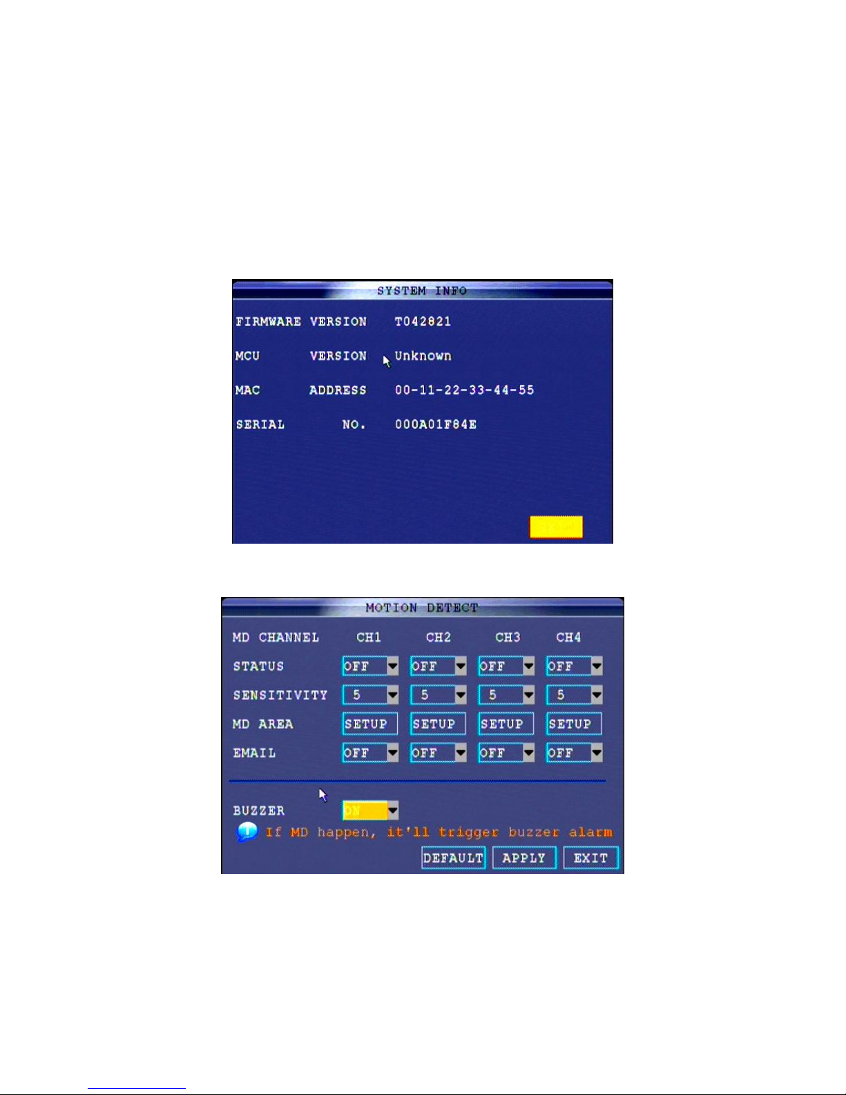
2.2.3.5.2 INFO
Here to check the software version, SCM version, MAC address and serial number in system information.
2.2.3.5.3 MD (Motion Detection)
To set the motion detection for each channel
.
STATUS: Select ON to active the motion detection function.
SENSITIVITY: There’re five options to set. The number is more, the sensitivity is easier to trigger. As usual, we
suggest 2.
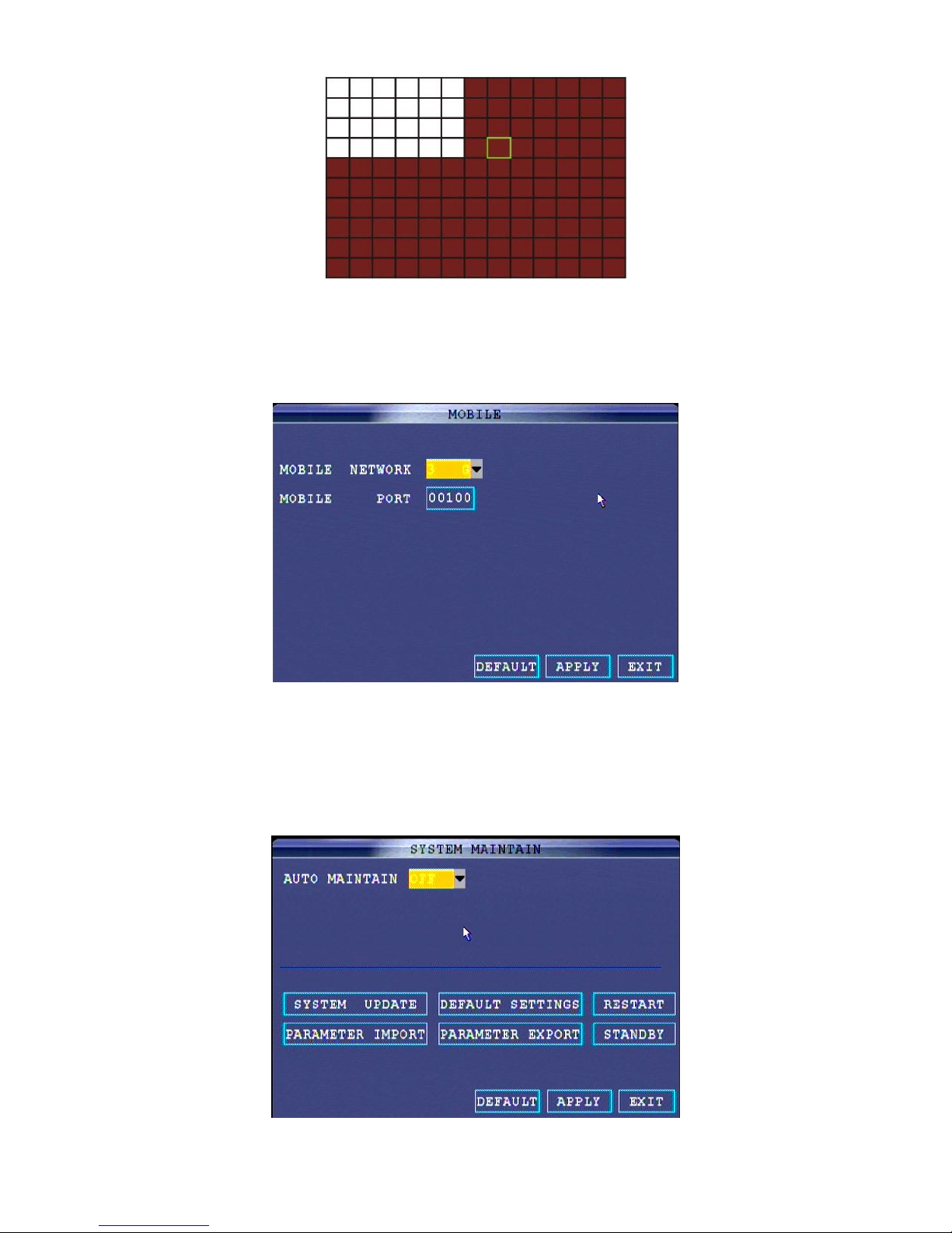
MD Area: To select the motion detection area. Click SETUP to set. Each channel has corresponding regional
motion detecting setting, RED area means it have activated motion detection, transparent block means it have
not activated motion detection. Picture is below:
Page 21
85XX Series Network DVR User Manual……………………………………………………………………….V1.0
- 21 -
EMAIL: To set the email sending function when the motion detection area is active.
Buzzer: To set the buzzer ON or OFF.
Notice: Buzzer could be set disable in alarm setup menu.
2.2.3.5.4 MOBILE
It supports smart mobile surveillance, to set the mobile phone network and mobile port.
Mobile Network: there are 2.5G、2.75G、3G options. As usual, we suggest 3G.
Mobile Port: input the number you want to set for mobile phone port.
Notice: According to local mobile phone operators and your phone support of Web standards to choose. If you
are not sure your mobile phone supports Web standards, you have to contact with your phone vendor.
2.2.3.5.5 MANTENANCE
There’s system maintenance, upgrade, default setting and restart system.
Page 22
85XX Series Network DVR User Manual……………………………………………………………………….V1.0
- 22 -
AUTO MAINTAIN: if set in ON, the system will maintain the system very DAY, WEEK, and MONTH.
SYSTEM UPDATE: it’s to update the system through USB driver.
DEFAULT SETTING: to set the system in default, and all the data and setting will be deleted.
RESTART: to restart the system.
PARAMETER IMPORT: to import the DVR system setting parameter through USB.
PARAMETER EXPORT: to export the DVR system setting parameter through USB.
STANDBY: to set the DVR in standby.
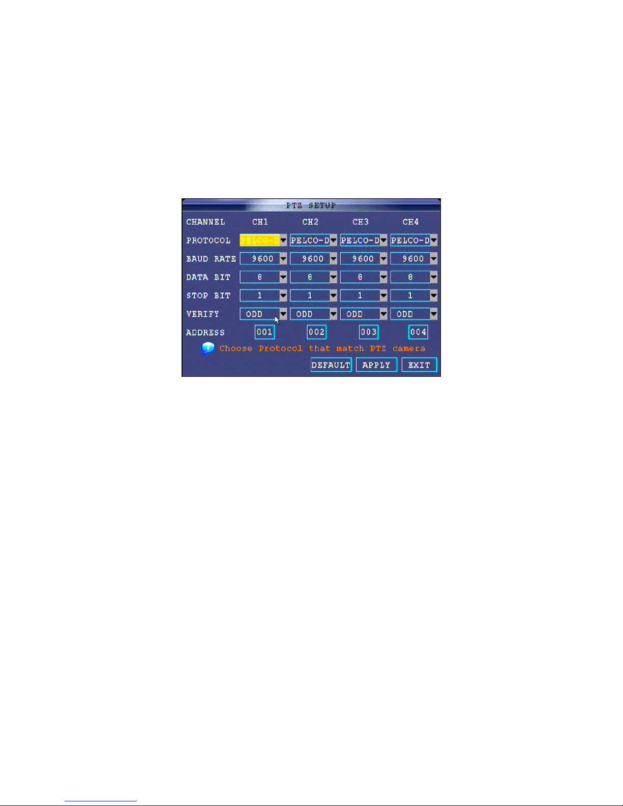
2.2.3.5.6 PTZ
Use PTZ settings menu can set the parameters for the connected PTZ cameras.
Notice: Users could learn the info of PTZ camera form the user manual, include the PROTOCOLE and Bit rate.
PTZ SETUP
PTZ SETUP:
1. Connection: Connect the PTZ through BNC and 485A(TX,+), 485B(RX,-) ports and power socket, there’s
detail in PTZ camera instruction.
2. Protocol: choose PELCO-D or PELCO-P as a protocol which is the same with PTZ. In 8CH DVR, there’s
“NEXT PAGE” for 5
th-8th
channel.
3. Baud Rate: there are 1200, 2400, 4800 and 9600 options.
4. Data Bit: there are 5, 6, 7 and 8 options
5. Stop Bit: there are 1 and 2 options.
6. Verify: there are Odd, Even, Mark, Space and None options.
7. Address: 001~255 are available to input if you use virtual keyboard, please refer to your PTZ camera
specification to know more.
8. Click APPLY to reserve and turn to main menu.
9. Click EXIT to exit the entire window.
2.2.3.5.7 NETWORK
Set network and DNS in network setting menu.
Page 23
85XX Series Network DVR User Manual……………………………………………………………………….V1.0
- 23 -
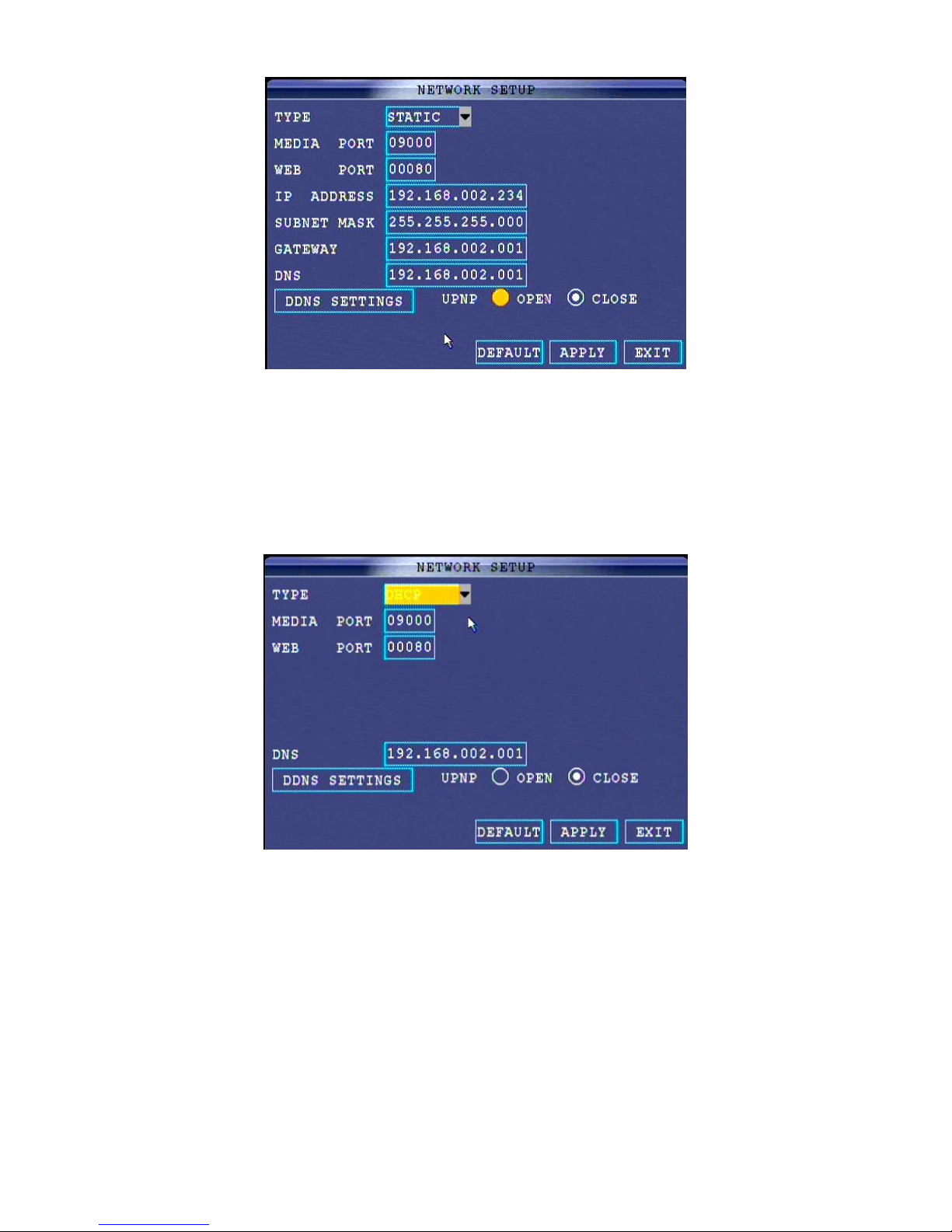
Network setup:
There are DHCP, PPPOE and STATIC three network connection type. The network setting steps is as
following,
1. Choose Network type:
A. DHCP
If select the DHCP, before setup, please make sure the DVR is connected to router server. While choose
DHCP, then DVR will get the IP address automatically through router server, and the DVR will restart. Make
sure the UPNP is set in ON status. After restart, the IP address will show in NETWORK.
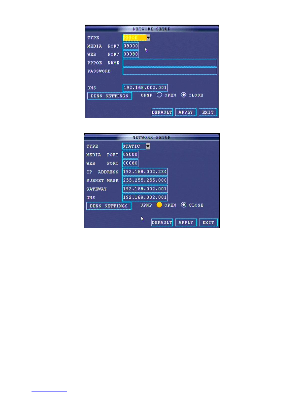
B. PPPoE
If select PPPoE, before setup, please make sure the DVR is connected to modem or network socket directly,
not router server. While choose PPPoE, please input your PPPoE account and password. Make sure the
UPNP is set in ON status.
Page 24
85XX Series Network DVR User Manual……………………………………………………………………….V1.0
- 24 -
C. STATIC
While select STATIC, and then input the IP address, subnet mask, gateway and DNS address.
2. Open the ports in router server.
There’re few ports need to open in router server, the web port, media port, and mobile phone port. The default
port is as follows,
Media port: 9000
Web port: 80
Mobile phone port: 100
Note:
A. If only remote access in LAN, the web port is necessary.
B. If want to remote access through outside internet, the Media port and Web port is necessary.
C. If want to remote access through mobile phone, the media port, web port and mobile port is necessary.
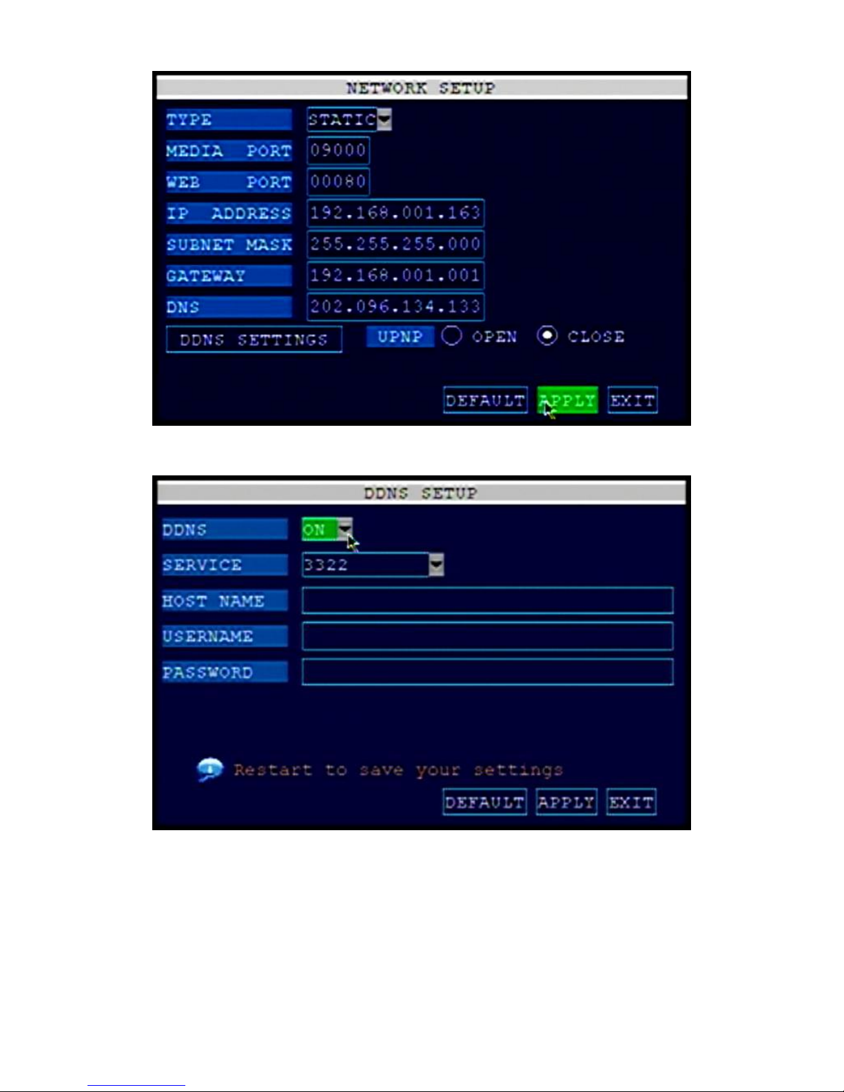
3. Click APPLY to save the setting, and system will restart.
4. Remote access through outside internet.
A. DHCP
After the system is restart, the IP address will be generated from router server. Copy the IP address and input
in IE browser to remote access.
B. PPPoE
After the system is restart, the IP address will be shown. Copy the IP address and input in IE browser to
remote access.
Page 25
85XX Series Network DVR User Manual……………………………………………………………………….V1.0
- 25 -
C. STATIC
After the system is restart, login the router server to see the router server running status, there’s a IP address
for router server, then copy this IP address and input IE browser to remote access.
5. DNS
This is the server of DNS, as usual, you could ignore this detail, the system will generate if you choose DHCP
or PPPoE. If you choose STATIC, the DNS is the same with your computer.
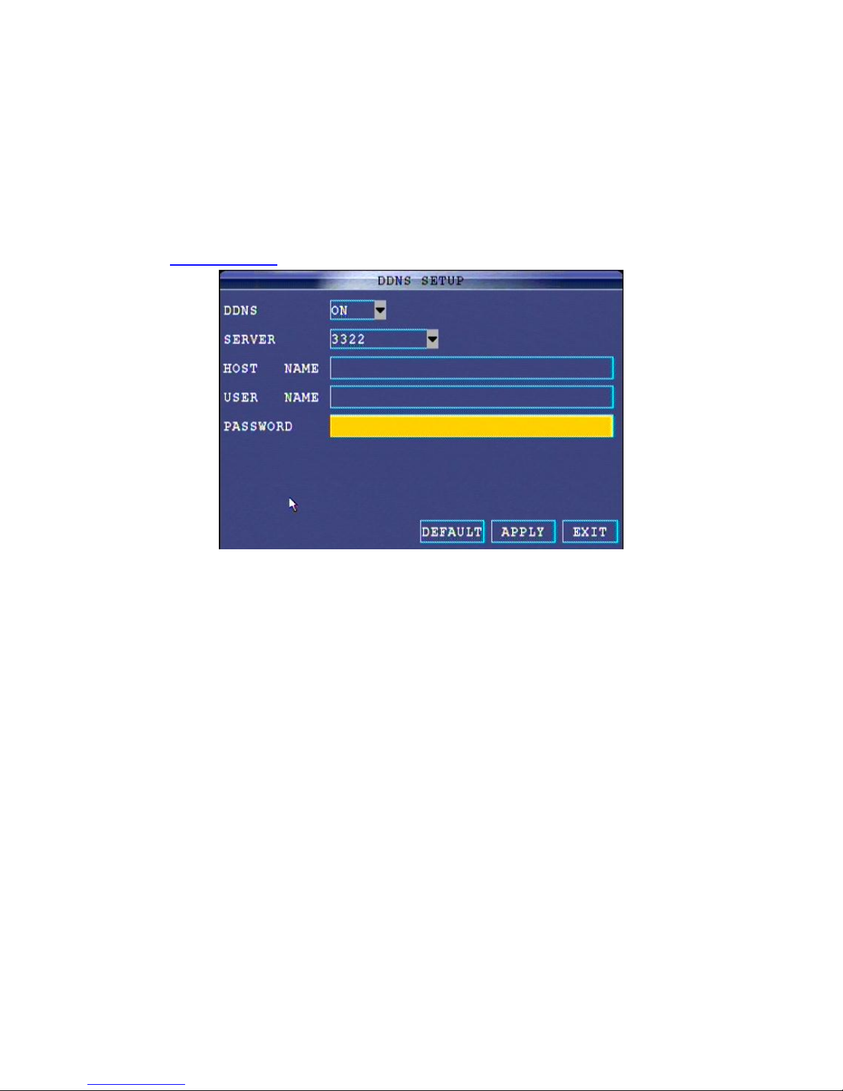
6. DDNS
This is function is allow to remote access from outside internet by your own dynamic address. There’re four
default DDNS provider, 3322, DYNDNS,Perfecteyes and JSJDVR.COM. As usual, we suggest DYNDNS.
Please go to www.dyndns.com to register one account.
A. Select ON to enable the DDNS function.
B. Select the DDNS provider “DYNDNS”.
C. Input the host address, which is the address you register in DYNDNS, which also will be confirmed by
email the DYDNS sent if register successfully, for example XXX.dyndns.com.
D. Input your DYNDNS account.
E. Input your DYNDNS password.
F. Click APPLY to reserve the setting, even in NETWORK menu.
G. The system will be restart.
7. UPNP
The UPNP is one of protocols in PC. If you select DHCP and PPPoE network type, you need to set the UPNP
in ON status, otherwise you can’t remote access from outside internet. If you set the UPNP in ON, the PC in
LAN can find the DVR, and the router server will match the media port, web port automatically if double click
the DVR icon in PC, then you could access through IE browser.
NOTE: JSJDVR.COM SERVER GUIDE
1. In DDNS server, there’re following server providers, such as: 3322, DYNDNS, Perfecteyes, and
JSJDVR.COM. After set the network and enable DDNS function, select the JSJDVR.COM, and just click
REGISTER for registration. After success, the DVR could be access by this new registered dynamic domain
address.
2. User guides:
A. Set the LAN in static network, and confirm to access successfully in LAN.
Page 26
85XX Series Network DVR User Manual……………………………………………………………………….V1.0
- 26 -
B. Open web and media ports in router server, and enable the DMZ server function as well. And confirm to
access successfully in WAN by public IP address of router server.
C. After confirm it could be accessed by LAN and WAN, then set the DDNS in ON. There’re 3322, DYNDNS,
perfecteyes, and JSJDVR.COM.
D. Select JSJDVR.COM provider and input the sub domain name you want (Arabic number or Alphabet up to
Max. 20 characters) and password, after 5 seconds, there’s feedback message from server to showing
whether the registration is success or not. There’re two reasons for unsuccessful registration, one is the DVR
is not connected to internet. Please make sure the DVR could be accessed by public IP address before
bounding the JSJDVR.COM domain, thus please check the setting of network first. The other is the sub
domain has been registered by others, which have to change another domain to achieve.
Page 27

85XX Series Network DVR User Manual……………………………………………………………………….V1.0
- 27 -
At last, please do make sure the DVR is accessed by public IP address before to bind the dynamic domain
of DVR. Only in this case, the sub domain could be registered to server.
The dynamic domain servers of JSJDVR.COM support 15,000pcs DVR online simultaneously.
2.3 Touch-screen user manual(F8504FP/F8508F/F8504CP/F8508C)
In order to use the DVR with touch-screen better, please read the manual carefully before using it.
After turning on the DVR, enter this page, wait… Touch the screen for 3 seconds by hand or touch-pen, it will
appear.
Page 28

85XX Series Network DVR User Manual……………………………………………………………………….V1.0
- 28 -
Click main menu and login
click basic setting and login
click audio setting and login
Page 29
85XX Series Network DVR User Manual……………………………………………………………………….V1.0
- 29 -
click revise touch-screen and login
Click the cross center by hand or touch-pen. After clicking the first cross, it will appear the second in the middle.
Click it again and it will appear the third on the right. Click it and it will exit automatically
Click exit. You can use the touch-screen freely now.
Note: the first time you use the touch-screen, it may be imprecise. Click by mouse and login the page to revise
touch-screen.
Page 30
85XX Series Network DVR User Manual……………………………………………………………………….V1.0
- 30 -
Chapter 3 IE Remote Access
3.1 Features
The system itself has the IE based software that it can allow you to remote control the system via WAN or
Internet. So far, the DVR only support the browser which is developing on the base of Windows IE.
To install software via the system based IE to make you remote access from internet conveniently. DVR
supports C/S, B/S construction, WAN and LAN, as well as IP and domain name accessing.
System request:
We recommend user to use Window XP, Window Vista OS, and IE6.0 or 7.0 version.
3.2 Login
Once the system is connected to LAN, you can login via IE.
Note: Make sure the network setting in DVR is correct, and the ports have been open in router server. When
the system is connected to LAN or WAN, you could remote access through LAN or WAN.
A. Input the IP address into the IE browser. (i.e.: http://192.168.2.212, and the web port is 9098.)
B. Set the ActiveX all in ENABLE before you login, the IE browser will remind you to install the ActiveX
software, then click to install.
C. After installation, refresh the IE browser, and there’s login window will be shown.
Note:If there’s password set in DVR, input the admin or user password. Only the administrator has authority to
change the system setting.
D. Select the network type and language.
Page 31

85XX Series Network DVR User Manual……………………………………………………………………….V1.0
- 31 -
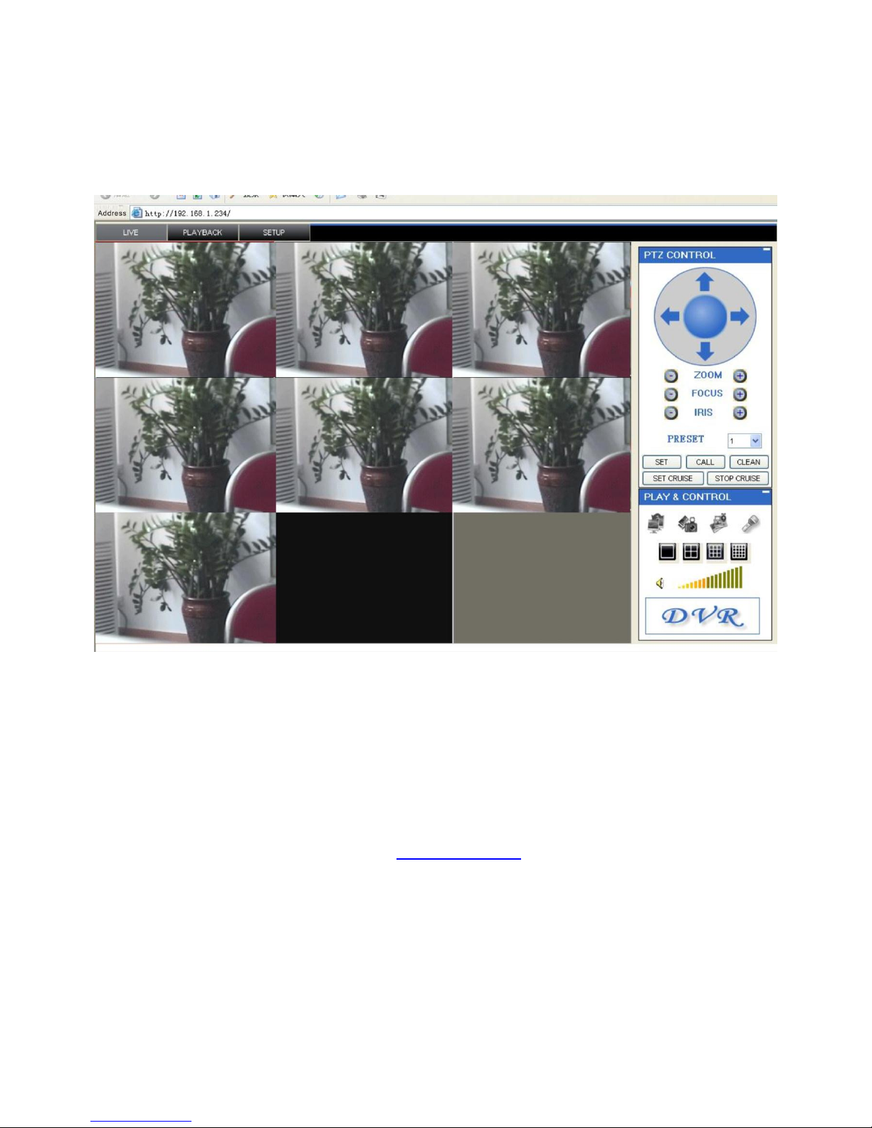
3.3 IE Browser Interface
The IE Browser interface will be displayed after logging.
① Function Module: There is LIVE, PLAYBACK and SETUP.
② Channel Name: Channel number or channel name is displayed at the top left corner.
③ Date and Time: It is shown the date and time in each channel.
④ Main Screen: It is show the live window.
⑤ PTZ Control: It controls the PTZ camera.
⑥ Function: Click the icon to show/hide windows, snap, record by manual, intercom.
⑦ Display Mode: Review by switching 1, 4, 9 and 16 windows.
⑧ Volume/Mute: Adjust the volume of one channel. Click mute icon to switch on and off.
Audio signal camera is a necessary for audio receiving and recording.
Page 32

85XX Series Network DVR User Manual……………………………………………………………………….V1.0
- 32 -
3.3.1 LIVE
The live window is realized with real time preview mode (multi-scene) under default setting.
A. Click the LIVE button in the main screen.
B. Click display icon, choose single, four or multi-channel to check main screen. Meanwhile, double click left
key to choose a channel to check in single mode.
C. Click to check or conceal all channel windows.
D. Click to start/stop to record and save the files to PC. More detail, please reference RECORD.
E. Choose one channel (frame become red), then click volume button to adjust. Click MUTE icon to switch
on/off.
Note: Intercom is not available so far.
3.3.1.1 Recording
Click to start record and save the video to PC. Click again to stop the recording.
Note: In default saving, the save path of recording file is to C:\DVR\[ip_address]\Record.
3.3.1.2 Sub-menu
Click right key in one channel, then show a sub-menu.
This submenu includes open window, close, open all windows, close all windows, start and stop recording.
3.3.1.3 PTZ Control
This function is active only there’s PTZ is connected to DVR.
PTZ Control:
A. Choose the channel is connected PTZ camera.
B. Click discretion key to adjust camera view.
Page 33

85XX Series Network DVR User Manual……………………………………………………………………….V1.0
- 33 -
C. Click +/- to control zoom, focus and iris.
D. Exit presetting.
E. Click setting, transferring and clear to control presetting further.
3.3.1.4 Snap
Click to snap the pictures of current channel in main screen.
The default picture is saved as BMP format and default save path in:(C:\DVR\[ip_address]\...)
3.3.2 Playback
Click PLAYBACK to enter the search and playback menu.
Record playback menu:
A. Click PLAYBACK in main screen, then the screen will become grey.
B. Click REFRESH under the calendar to list the record files.
Note: Time icon represents record normally; exclamatory mark represents alarm recording (alarm, loss, motion
event).
C. Double click one record file to playback in main screen. The icon of record will become when the file is
playback. And there’s playback function button will be shown under the playback bar.
Page 34

85XX Series Network DVR User Manual……………………………………………………………………….V1.0
- 34 -
The purple color process bar shows download status, the green color progress bar shows playback process.
You can click or move green signal (green to orange) to play fast forward or fast back.
Pause/Play
Stop
Fast forward
Slow play
To next frame and pause
Search
Search the system video recording via the calendar and menu.
A. Click or to change the Month. The date which has record file will be boldfaced.
B. Click the date, then record will show in the file list.
C. Choose one channel or all channels in pull-down menu, then click SEARCH.
D. In the pull-down menu, choose normal (recording), alarm and all, and then click SEARCH.
E. Double click one record in file list to play in the main screen.
Page 35

85XX Series Network DVR User Manual……………………………………………………………………….V1.0
- 35 -
Remote Backup
Backup the record files and save the files to the PC.
Remote backup file:
A. Click PLAYBACK in the top main screen.
B. Choose the date in the calendar, and then click REFRESH.
C. Double click one recording in file list to play.
D. Click BACKUP to C: /DVR/[ip_address]/Backup
Note:
A. When you playback a record file, meanwhile this record is also backup to your PC.
B. Play the professional player to backup the record files.
3.3.3 Setup
To configure the system setting in remote access. Please pay attention that if there’s someone is operating the
DVR, even the menu is open, you can’t set anything when remote access in IE browser.
The setup including Record, Alarm, PTZ, Network, System, Maintain and Host Info.
3.3.3.1 Record
Click
Page 36

85XX Series Network DVR User Manual……………………………………………………………………….V1.0
- 36 -
to enter record setting interface, you could set the DVR record parameter in remote access, which is the
same as in GUI of DVR. The detail please references the Record in Chapter 2.
3.3.3.2 Alarm
Click
to enter the alarm setting interface; you could set the DVR alarm parameter in remote access, which is the
same as in GUI of DVR. The detail please references the alarm in Chapter 2.
Page 37

85XX Series Network DVR User Manual……………………………………………………………………….V1.0
- 37 -
3.3.3.3 PTZ
Click
to enter the PTZ setting interface; you could set the DVR PTZ parameter in remote access, which is the same
as in GUI of DVR. The detail please references the PTZ in Chapter 2.
3.3.3.4 Network
Click
to enter network setting interface, you could set the DVR network parameter in remote access, which is the
same as in GUI of DVR. The detail please references the network in Chapter 2.
3.3.3.5 System
Page 38

85XX Series Network DVR User Manual……………………………………………………………………….V1.0
- 38 -
Click
to enter system setting interface, you could set the DVR system parameter in remote access, which is the
same as in GUI of DVR. The detail please references the system in Chapter 2.
BANDWIDTH: Select the amount of bandwidth in 128k, 192k, 256k, 384k, 512k and1024k which is your
broadband width, this bandwidth depends on the place, normally around 256 or 384 kbps.
SAVE PATH: Snap pictures and recording video save path.
3.3.3.6 HOST INFO
Click to enter host information setting interface; this interface shows HDD status, remain
record time, firmware version, MAC Address, and all the information is fixed.
Page 39

85XX Series Network DVR User Manual……………………………………………………………………….V1.0
- 39 -
4 VCA software operation manual
(A8504FP/A8504CP/A8508F/A8508C)
4.1. Installation
Attention:
A. The IP address which is marked in VCA module is the device control address. If the gateway is different,
please amend the device IP address or change net mask of TCP/IP property in computer of network to
255.255.0.0.
B. The device ID is “root”, and with password of “pass”.
C. There’re two software in CD, “MSXML4.0” for ActiveX and “admintools” for search which could search the
DVS device in LAN.
4.1.1 Install the MSXML4.0 software
Find the “MSXML4.0” setup folder and double click to install, and there’s window will be shown as follows,
Click NEXT to finish the installation.
Click NEXT
Page 40

85XX Series Network DVR User Manual……………………………………………………………………….V1.0
- 40 -
Select Agree option
Click NEXT
Click NEXT
Default installs and saves
Click NEXT
Customize the installation
Page 41

85XX Series Network DVR User Manual……………………………………………………………………….V1.0
- 41 -
4.1.2 Amend the IE browser security option
Click the OPTION in IE browser, select PROPERTY and click PRIVATE to set. Click off the “Stop pop-up
window”.
Click FINISH to finish
the installation
Click off
Click OK
to save
Page 42

85XX Series Network DVR User Manual……………………………………………………………………….V1.0
- 42 -
4.2. Login
4.2.1 Login the VCA
Run the IE browser and input the IP address of VCA which could be found at the bottom of product or run the
“admintools” to search the device and identify the IP address.
Click OK
Click RUN
Install ActiveX
Page 43

85XX Series Network DVR User Manual……………………………………………………………………….V1.0
- 43 -
After install the ActiveX and refresh the IE browser, the interface will be shown.
4.2.2 Live window OSD configuration
Click right button of mouse to enter the property menu,
Video: to set the information to show in live window, which could set to show the information such as codec,
frame type, dts, bit rate, fps, etc.
Click Install
Stream could be selected
PTZ control
Page 44

85XX Series Network DVR User Manual……………………………………………………………………….V1.0
- 44 -
Snap and Record: to snap the image and record.
Event: to show the information of event, alarm and USB/SD status.
Page 45

85XX Series Network DVR User Manual……………………………………………………………………….V1.0
- 45 -
VCA: to show the VCA tracking information.
4.2.3 PTZ Control
4.3. Setup
Click setup to enter the setup interface.
Click to set the PTZ
PTZ control platform
Click to show the
preset position
Page 46

85XX Series Network DVR User Manual……………………………………………………………………….V1.0
- 46 -
Input the account and password (default account is “root”, and password is “pass”).
4.3.1 Basic Configuration
There’re User, WEB server and Date & Time setting.
Page 47

85XX Series Network DVR User Manual……………………………………………………………………….V1.0
- 47 -
4.3.1.1 User
To add, modify, cancel user information in this menu.
4.3.1.2 WEB Server
To set the WEB login server and port.
4.3.1.3 Date & Time
To set the device date and time. Please pay attention that the date and time must be the same with comuter,
and DVR device.
HTTPS protocol
HTTP protocol
Page 48

85XX Series Network DVR User Manual……………………………………………………………………….V1.0
- 48 -
4.3.2 Video & Audio
To set the video standard and audio decode.
4.3.2.1 Video Input
To set the video standard system and image property.
Select time zone
Set Date and Time
Page 49

85XX Series Network DVR User Manual……………………………………………………………………….V1.0
- 49 -
4.3.2.2 Built-in Text
To set the content, date and time.
4.3.2.3 Codec
To set the codec and resolution.
Select the video standard,
must be the same with
DVR and camera
Support dual video streaming
Text position
Page 50

85XX Series Network DVR User Manual……………………………………………………………………….V1.0
- 50 -
Select the stream
Video codec
Resolution
Variable Bitrate to
change
Constant Bitrate
Three compression,
such as MJPEG,
MPEG4, H.264
Page 51

85XX Series Network DVR User Manual……………………………………………………………………….V1.0
- 51 -
4.3.2.4 Snap
To snap the image of preview.
4.3.3 Event Configuration
To set the alarm input/output, VCA, motion detection, etc.
Support multiple resolution
Image format
Image resolution
Customize image size
Page 52

85XX Series Network DVR User Manual……………………………………………………………………….V1.0
- 52 -
4.3.3.1 DI:
To trigger the setting when there’s alarm input.
4.3.3.2 DO:
To set the alarm output when the alarm is triggered.
Alarm input and alarm
output
To set the posting notification
message
Page 53

85XX Series Network DVR User Manual……………………………………………………………………….V1.0
- 53 -
4.3.3.3 Video:
When there’s video loss, the alarm will be triggered.
4.3.3.4 Motion Detection:
To set the motion detection in the area to triggered the alarm.
To set the posting notification
message when there’s video loss
Page 54

85XX Series Network DVR User Manual……………………………………………………………………….V1.0
- 54 -
4.3.3.5 VCA:
To set the VCA output
4.3.3.6 Network:
To set the alarm when the IP address is changed.
To set the area of alarm when
motion detection is triggered.
Page 55

85XX Series Network DVR User Manual……………………………………………………………………….V1.0
- 55 -
4.3.3.7 Health:
To set the device temperature, DSPload.
4.3.4 System Options
To set the network transmission protocol.
To set the triggered when
IP address is changed
Page 56

85XX Series Network DVR User Manual……………………………………………………………………….V1.0
- 56 -
4.3.4.1 TCP/IP:
To set the TCP/IP protocol and IP address of device.
4.3.4.2 NAT:
To set the public IP address in order for remote access from outside internet.
Set the IP address via DHCP
Input the IP address by manual
Page 57

85XX Series Network DVR User Manual……………………………………………………………………….V1.0
- 57 -
4.3.4.3 NTP:
To set the NTP server.
4.3.4.4 UPnP: :To set the PnP protocol.
4.3.4.5 USB/SD Storage:
To set the camera USB/SD card save path.
To set the DNS for remote
access from outside internet
Synchronize the device and server
Set the local device
as SNTP server
Page 58

85XX Series Network DVR User Manual……………………………………………………………………….V1.0
- 58 -
4.3.4.6 USB Wireless LAN:
To set the USB wireless transmission status.
4.3.4.7 RTSP/RTP:
To set the video streaming transmission and protocol.
Device information
Show the device
Format the device
Show the device in LAN
through wireless
Input the password to wireless
Page 59

85XX Series Network DVR User Manual……………………………………………………………………….V1.0
- 59 -
4.3.4.8 mDNS:
To set the mDNS option.
Set in ENABLE
Set in ENABLE to
see the live video
Multiple cast or Unit cast
Need to enable this option
when there’s second stream
Page 60

85XX Series Network DVR User Manual……………………………………………………………………….V1.0
- 60 -
4.3.4.9 SMTP:
To set the email SMTP server in order to send the email when alarm is triggered.
4.3.4.10 AVI Record:
To set the camera USB/SD record option.
Multiple cast information
Sender information
SMTP Server
Input the account and
password
Enable AVI record
Set VCA record
automatically
Page 61

85XX Series Network DVR User Manual……………………………………………………………………….V1.0
- 61 -
4.3.4.11 LED:
To set the LED shining rule in front panel.
4.3.4.12 DDNS:
To set the IP address of device to match the DDNS server.
Record bit rate
Record resolution
Set the record
processing rule
Set the LED color for
different event
Set the LED color for
different video record
Page 62

85XX Series Network DVR User Manual……………………………………………………………………….V1.0
- 62 -
4.3.5 IO Configuration:
To set the alarm input, output and configuration of ports.
4.3.5.1 DI/DO
ENABLE DDNS
DDNS server information
DDNS server account
and password
Alarm input voltage
Alarm triggered type
Alarm output status
Alarm input
triggered
Alarm output
triggered time
Name of alarm
device input/output
Alarm input status
Page 63

85XX Series Network DVR User Manual……………………………………………………………………….V1.0
- 63 -
4.3.5.2 UART
4.3.6 Maintenance:
To maintain the device and see the log information.
4.3.6.1 Upgrade
4.3.6.2 log
To set the log file and see log information
PTZ protocol and
address
PTZ baud rate
Stop bit position
Set the device to be
upgraded through network
Enable to save the
log automatically
Page 64

85XX Series Network DVR User Manual……………………………………………………………………….V1.0
- 64 -
4.3.6.3 Website
To set the VCA result to show in website
4.3.7 Motion Detection:
To set the camera motion detection in the area.
4.3.8 About
4.3.8.1 Version
Enable to show the VCA
result in the website
Area 1
Area 2
Version of device
Product parameter
ActiveX version
Page 65

85XX Series Network DVR User Manual……………………………………………………………………….V1.0
- 65 -
4.3.8.2 License
4.4. VCA setting
4.4.1 Setup before VCA
Attention: Before set the VCA function, please make sure the Video/Audio setting is as bellows。
4.4.1.1 Switching VCA On and Off
By default, VCA is disabled. In order to enable VCA it must be activated. Select the VCA menu and then the
Enable/Disable sub menu. Tick the Enable check box under Analytics and select the required mode.
4.4.1.2 Analytics Mode
VCA offers two modes of operation: Moving and Stationary Objects or Abandoned Objects. If the detection
scenario requires detection of abandoned objects, select the Abandoned Objects mode, otherwise select the
Moving and Stationary Objects mode.
4.4.1.3 Camera Shake Cancellation
The camera shake cancellation function is used to improve the VCA performance with cameras that are prone
to shake. By default, camera shake cancellation is disabled. If your installation suffers from camera shake
problems, enable this function to improve the VCA performance. If camera shake is not an issue in your
installation, best performance will be achieved with this setting disabled.
Video/Audio
Codec
Select the second stream
Click off “Enable”
Page 66

85XX Series Network DVR User Manual……………………………………………………………………….V1.0
- 66 -
4.4.1.4 Enabling Metadata Streaming
In order to visualize the VCA output, metadata streaming must be enabled for RTP. Select System Options
and then the RTSP/RTP sub menu:
4.4.1.5 License
Once an activation code has been received from your hardware supplier, it's simply a case of entering the
code on the appropriate web page. Select the the Activation menu:
Page 67

85XX Series Network DVR User Manual……………………………………………………………………….V1.0
- 67 -
Enter the activation code and click "Apply". If the activation code is valid, the activated features will be
displayed in the "Installed Licenses" box.
4.4.2 Configuration of Zones and Rules
In order to create some useful output, it is necessary to configure detection zones and detection rules. The
detection zones and rules are configured by selecting VCA and then the Zones and Rules sub menu:
4.4.2.1 Tracking Display
The tracking display window shows all moving and stationary targets that are currently being tracked by the
engine. Objects that have triggered a rule are displayed in red. Conversely, objects that have not triggered a
rule are displayed in yellow.
This snapshot shows a detection zone, in red and a detection line, in green.
The tracking display window is useful for predicting how the rules will operate. By examining how the trails of
the objects intersect the detection zones and lines, it is possible to determine how the rule can be optimally
configured.
Page 68

85XX Series Network DVR User Manual……………………………………………………………………….V1.0
- 68 -
4.4.2.2 Properties Inspector
The properties inspector allows the user to assign detection rules to detection zones and detection lines.
Available rules will depend on the features available and settings applied, and may include the following:
Object presence
Object entered
Object exited
Object appeared
Object disappeared
Object stopped
Object dwell
Object direction
Object speed
Object Tailgating
The Abandoned Object rule is also available depending on the features available and settings applied. To get
started straightaway on this rule, see the Abandoned Object topic.
4.4.2.3 Customizing the Tracking Display
The tracking display window can be customized to show various levels of tracking data. Simply right click on
the tracking display window and select the Display option:
4.4.2.3.1 Display Blobs
By default, the blobs are not displayed. It's possible to switch the blob display on in order to observe how the
algorithm performs in different scenarios. Blobs are displayed in turquoise, as illustrated in the figure.
4.4.2.3.2 Display Objects in Multiple Colors
Select this option to toggle between 2-color display mode (alarmed objects in red, non-alarmed objects in
yellow), or multi-color displayed mode. In multi-color display mode, objects are displayed in a color selected by
the system.
4.4.2.3.3 Display Non-Alarmed Objects
By default, all objects are displayed: alarmed objects in red; and non-alarmed objects in yellow. The display of
non-alarmed objects and their trails helps optimally configure the rules by allowing the user to see how the
detection zones and object trails intersect. Uncheck this item to switch the display of non-alarmed objects off.
Page 69

85XX Series Network DVR User Manual……………………………………………………………………….V1.0
- 69 -
4.4.2.3.4 Display Object Height
Check this option to display the object height. This option is only available when the camera has been
calibrated.Display Object Speed
Check this option to display the object speed. This option is only available when the camera has been
calibrated.
4.4.2.3.5 Display Object Area
Check this option to display the object area. This option is only available when the camera has been calibrated.
4.4.2.3.6 Display Object Classification
Check this option to display the object classification. This option is only available when the camera has been
calibrated。
4.4.2.4 Creating Detection Zones and Lines
In order to detect events of interest, detection zones and lines must be defined. Detection zones define an area
of interest. Detection lines are similar to detection zones but they define a perimeter instead of a region.
4.4.2.4.1 Creating a Zone or Line
To create a zone, either double click the left mouse button or right click and select Zone/Line... Create zone:
To create a line, right click and select Zone/Line... Create line
4.4.2.4.2 Editing Zones and Lines
Zones and lines can be edited to be any shape or size. Zones and lines are controlled by manipulating "nodes"
that represent the zone/line vertices. To change the shape of a zone or line, simply grab a node with the left
mouse button and drag it to the desired location:
Page 70

85XX Series Network DVR User Manual……………………………………………………………………….V1.0
- 70 -
4.4.2.4.3 Adding and Removing Nodes
Zones and lines can be tailored to any scenario by simply adding more nodes to define the shape required. To
add a node, simply double click on the zone or line at the point where the new node should be added. Nodes
can be deleted by right clicking on node and selecting Node…remove
4.4.2.4.4 Non Detection Zones
In some situations, especially where the scene is busy, objects tracked in some areas can interfere with
detection zones in other areas. For example, on a windy day, moving foliage can generate false alarms that in
some situations could be tracked through a detection zone. In order to minimize such issues, it is possible to
configure "non-detection" zones, where nothing is detected or tracked.
4.4.2.5 Detection Rules
4.4.2.5.1 VCA presence
Once some detection zones and/or lines have been configured, it's possible to define some detection rules that
apply to the zones/lines. By default, zones and lines are automatically configured to detect object presence.
The rules are defined in the Properties Inspector:
Page 71

85XX Series Network DVR User Manual……………………………………………………………………….V1.0
- 71 -
The properties inspector is context-sensitive to the zone selected. As different zones/lines are selected, so the
properties inspector changes to reflect the rules currently configured on that zone. Defining a rule is a simple
matter of checking the box next to the rule required. In all cases, the rules are configured with sensible default
values. Of course, these can be customized to suit the detection scenario. The selection of multiple rules on a
detection zone is supported.
4.4.2.5.2 Object Presence
Enable the object presence rule on the selected zone by checking the Presence box in the properties inspector
and click apply.Objects that are present inside a zone or pass through a line will trigger the rule and raise an
alarm.
4.4.2.6 VCA surveillance
4.4.2.6.1 Object Presence
Page 72

85XX Series Network DVR User Manual……………………………………………………………………….V1.0
- 72 -
4.4.2.6.2 Object Appear and Disappear
Enable the object appears and disappear detection by checking the corresponding check boxes in the
properties inspector and click apply.
An object appears alarm is raised when an object appears inside a detection zone. Note that this is different
from object entered detection since the object must be initially detected inside the zone without entering, e.g.
people appearing in a doorway, or cars appearing from an underground car park.
Conversely an object disappear alarm is raised when an object disappears inside a detection zone. Again, this
is different from object exit detection since the object must be tracked into the zone and then disappears
without exiting the zone.
4.4.2.6.3 Object Enter and Exit
Enable the object enter and exit detection by checking the corresponding check boxes in the properties
inspector and click apply.
An object entered alarm is raised when an object crosses from the outside to the inside of a detection zone.
Conversely, an object exited alarm is raised when an object crosses from the inside to the outside of a
detection zone:
Page 73

85XX Series Network DVR User Manual……………………………………………………………………….V1.0
- 73 -
4.4.2.6.4 Object Dwell
Enable the object dwell rule on the selected zone by checking the Dwell box in the properties inspector and
click apply. Objects that dwell inside a zone for longer than the defined amount of time will trigger the rule and
raise an alarm.
4.4.2.6.5 Object Stopped
Enable the object stopped rule on the selected zone by checking the Stopped box in the properties inspector
and click apply. Objects that are stopped inside a zone for longer than the defined amount of time will trigger
the rule and raise an alarm. The stopped time can be configured by simply clicking in the Time box on the
rule control and editing the value in-place.
Page 74

85XX Series Network DVR User Manual……………………………………………………………………….V1.0
- 74 -
4.4.2.6.6Object Speed
Enable the object speed rule on the selected zone by checking the Speed Filter box in the properties inspector.
Adjust the lower and upper speed limits to suit the detection scenario. Objects that travel within the bounds of
the configured speeds, through a zone or over a line trigger the rule and raise an alarm. Note that the camera
must be calibrated for this function to be available.
4.4.2.6.7 Object Class
Once the camera has been calibrated, it's possible to include or exclude specific object types in the detection
rules. Select and enable an Object Filter by checking the box. Select whether the rule should include or
exclude the object type. Select the object type to include or exclude. Apply the changes.
In this example, the rule has been configured to include detection of people only. As illustrated, the person
generates an alarm, but the vehicle is filtered out and does not trigger the alarm.
Page 75

85XX Series Network DVR User Manual……………………………………………………………………….V1.0
- 75 -
4.4.2.6.8 Object Direction
Enable the object direction rule on the selected zone by checking the Direction Filter box in the properties
inspector. Adjust the direction and acceptance angle to suit the detection scenario. Objects that travel in the
configured direction (within the limits of the acceptance angle) through a zone or over a line trigger the rule and
raise an alarm.
Enable the object tailgating rule on the selected zone by checking the Object Tailgating box in the properties
inspector. Adjust the time threshold to set the minimum allowable time between successive object detections.
Object tailgating is defined as an object crossing a line or zone within a certain time after an object has already
crossed the line or zone. If an object crosses a line or zone, and another object crosses the same line or zone
within the specified time window, the Object Tailgating filter will be triggered.
In this example, Object 1 is about to cross a detection line. Another object (Object 2) is following closely behind.
The tailgating detection threshold is set to 5 seconds. That is, any object crossing the line within 5s of an object
having already crossed the line will trigger the Object Tailgating filter.
4.4.2.6.9 Object Tailgating
Page 76

85XX Series Network DVR User Manual……………………………………………………………………….V1.0
- 76 -
Object 2 crosses the line within 5 seconds of Object 1. This triggers the Object Tailgating filter.
4.4.2.6.10 Abandoned Object
VCAsys can be configured to generate an alert highlighting an abandoned object. Suspicious objects can be
detected when carried into the scene and planted by a person as well as when dropped or thrown into the
scene. Enable the abandoned object mode by selecting the Enable/Disable link, selecting the Abandoned
object tab and clicking on the apply button.
Enable the abandoned object rule on the selected zone by checking the Abandoned Object box in the
properties inspector. An object that is left inside a zone for longer than the configured time period will trigger
the rule and raise an alarm.
Note that this behavior is different from the object stopped and appear rule. The stopped rule triggers the alarm
after an object is tracked into the zone and stops for a defined time period. The appear rule triggers the alarm
Page 77

85XX Series Network DVR User Manual……………………………………………………………………….V1.0
- 77 -
after a moving object appears inside the zone. The abandoned object rule triggers the alarm after an object is
dropped inside the zone and left for a defined time period.
4.4.2.6.11 Stationary Object Hold-on Time
The stationary object hold-on time is the time which the tracker will keep tracking an object once it has been
detected as stationary or abandoned. After an abandoned object has been detected, the object will continue to
be tracked for the time configured determined by the stationary object hold-on time. The default value is 60
seconds, but this can be changed in the advanced settings.
4.4.2.7 VCAretail
4.4.2.7.1 Counting line
A counting line is a detection filter optimized for bi-directional object counting (e.g. people or vehicles) in busier
detection scenarios. Examples of such applications may include:
6.4.2.0.0、People counting with overhead cameras in a retail environment.
6.4.2.0.1、Vehicle counting with overhead cameras on public highways.
The counting line filter is only enabled when the unit has been configured with a VCAretail license, and
typically will generate a higher accuracy count than using the counters provided as part of VCAsurveillance.
NOTE: The maximum number of counting line filters that can be applied per video channel is 5.
Page 78

85XX Series Network DVR User Manual……………………………………………………………………….V1.0
- 78 -
4.4.2.7.2 Enabling the Counting Line
Enable the counting line filter on a detection line in the desired direction(s) by checking the appropriate box in
the properties inspector. An event is generated every time an object crosses the line in the selected direction. If
multiple objects cross the line together, multiple corresponding events are generated. The events generated by
the counting line can be tied to counters in the normal manner.
4.4.2.7.3 Assigning Counters to Counting Lines
A counting line by itself simply generates events when an object to be counted is detected. In order to
actually count the events, counters (one for each direction) can be created and configured to count the
events generated by the line. To create counters, see the Counters topic.
4.4.2.7.4 Calibrating the Counting Line
In order to generate accurate counts, the counting line requires calibration. Unlike VCAsurveillance, this
cannot be performed at a general level for the whole scene using the 3D calibration tool. This is because the
counting line is not always placed on the ground plane: it may be placed at any orientation at any location in
the scene. For example, a counting line could be configured vertically with a side-on camera view.
Page 79

85XX Series Network DVR User Manual……………………………………………………………………….V1.0
- 79 -
Instead of the 3D calibration tool, the counting line has its own calibration setting. Two bars equidistant from
the centre of the line represent the width of the expected object. This allows the counting line to reject noise
and also count multiple objects.
To calibrate the counting line:
Select the counting line with the mouse.
Check the "Width Calibration" box under the Counting Line rule in the property inspector.
Use the mouse wheel or drag the calibration markers to adjust the distance between the calibration
markers until the distance is approximately the size of the objects to be counted.
The calibration width is displayed on the property inspector under the counting line rule. The figure
which is displayed is the calibration width expressed as a percentage of the screen width. This figure
can also be edited to change the calibration width.
The small markers on either side of the big markers indicate the minimum and maximum width which is
counted as a single object.
Apply the settings.
4.4.2.7.5 Calibration Diagnostics Mode
To enable the user to more accurately configure the calibration for the counting line, there is a diagnostics
feature which can be enabled to provide feedback of the counting results. To enable this mode, select the
"Metadata Format" ->"Counting Line Diagnostics" on the VCA Advanced Settings page .
Page 80

85XX Series Network DVR User Manual……………………………………………………………………….V1.0
- 80 -
When the diagnostics metadata is enabled, the diagnostics will appear as black and white lines on either side
of the counting line on the Zones and Rules page. Each line represents an object which was detected by the
counting algorithm. The width of the line shows the width of the object detected by the line. The last 5
detections are displayed for each direction with the latest one appearing closest to the counting line. Each
detection is counted as a number of objects based on the current width calibration. This is shown as follows:
Black line: Event not counted
Solid white line: Event counted as one object
Broken white line: Event counted as multiple objects indicated by the number of line segments.
Using the feedback from the diagnostics, the width calibration can be fine tuned to count the correct sized
objects and filter out spurious detections.
4.4.2.8 Counters
VCAsys also supports object counting. Any combination of detection zones or lines can be assigned to a
counter. Counters can be configured to perform any combination of incremental, decremental or occupancy
counting. Counter configuration is managed through the properties inspector in a similar way to the zone
configuration.
4.4.2.8.1 Creating Counters
To create a counter simply click the right mouse button and select Counters... Add Counter.
Page 81

85XX Series Network DVR User Manual……………………………………………………………………….V1.0
- 81 -
The counter name can be changed by clicking in the Name box on the rules control.
4.4.2.8.2 Assigning Rules to counters
Counters count triggers generated by rule violations. For example, if it is required to count the number of
objects entering a zone, a zone must initially be configured to raise an alarm every time an object enters it. The
zone can then be assigned to a counter and the counter will count the objects according to the type of counting
required (increment, decrement, occupancy).
In this example the red zone is configured to trigger when object travelling in the north direction are detected.
The counter has been configured to increment the count whenever the zone (Zone 0) is triggered. Currently
two objects have been counted.
4.4.2.8.2.1 Incremental Counters
When a zone is assigned to an incremental counter, the count will increment by 1 every time the zone is
triggered.
4.4.2.8.2 Decremental Counters
When a zone is assigned to a decremental counter, the count will decrement by 1 every time the zone is
triggered.
4.4.2.8.3 Occupancy Counters
When a zone is assigned to an occupancy counter, the counter displays the number of active triggers in the
zone. E.g. if there are 2 objects in the zone that triggered the detection rule, then the count will display 2.
Page 82

85XX Series Network DVR User Manual……………………………………………………………………….V1.0
- 82 -
4.4.2.9 Camera Calibration
Camera calibration is required in order for the VCA engine to classify objects into different object classes.
Once the camera has been calibrated, the engine can infer real-world object properties such as speed, height
and area and classify objects accordingly.
4.4.2.9.1 Calibration Page Elements
The following describes the purpose of each element of the calibration page. To get started calibrating straight
away, see the Calibrating a Camera topic.
4.4.2.9.2 3D Graphics Overlay
During the calibration process, the features in the video image need to be matched with a 3D graphics overlay.
The 3D graphics overlay consists of a green grid that represents the ground plane. Placed on the ground plane
are a number of 3D mimics that represent the dimensions of a person with the current calibration parameters.
The calibration mimics are used for verifying the size of a person in the scene.
4.4.2.9.3 Mouse controls
The calibration parameters can be adjusted as follows:
Click and drag the ground plane to change the tilt angle.
Use the mouse wheel to adjust the camera height.
Drag the slider to change the vertical field of view.
4.4.2.9.4 Other Graphical Tools
There are a number of other graphical tools that can be used to make the calibration process simpler and more
accurate.
4.4.2.9.5 Horizon Display
The horizon can be displayed by right clicking and checking the menu option. If the horizon is visible in the
video, it is possible to use this to set the tilt angle. Drag the grid until the horizon in the video matches the
graphical horizon.
Page 83

85XX Series Network DVR User Manual……………………………………………………………………….V1.0
- 83 -
4.4.2.9.6 Additional Mimics
Additional mimics can be added to verify the calibration configuration. Select the Add Mimic option from the
menu.
4.4.2.9.7 Grid Transparency
By default the ground plane is displayed in transparent mode such that the video is clearer. The transparent
grid can be toggled by selecting the corresponding menu option.
4.4.2.9.8 Virtual Ruler
The calibration configuration control supports a virtual ruler. This can be useful for measuring distances along
the ground plane to objects of known size such as road lane widths, car park space widths etc. The virtual ruler
is effectively a "measurement stick" that measures the distance between two points along the ground plane
(not heights).
To use the virtual ruler, simply right click anywhere a point on the ground plane to anchor one end of the ruler
and select the option from the menu. It is then possible to move the other end of the ruler around the ground
plane to measure the distance between the anchor point and the current mouse position.
To exit from the virtual ruler mode, click the right button. The ruler disappears.
Page 84

85XX Series Network DVR User Manual……………………………………………………………………….V1.0
- 84 -
4.4.2.10 Calibrating a Camera
Calibrating a camera is necessary in order to estimate object parameters such as height, area, speed and
classification. If you know the height, tilt angle and vertical field of view corresponding to your installation, you
can simply type the parameters in the appropriate boxes and apply the changes.
If however, you do not know, or are unable to find out the camera parameters, this topic provides a
step-by-step guide to calibrating a camera.
Step 1: Find some people in the scene
Find some people, or some people-sized objects in the scene. Try to find a person near the camera, and a
person further away from the camera. It is useful to use the Video Control button to pause the video so that the
mimics can be accurately placed. Place the mimics on top of or near the people. Enter in the known height or
estimated height.
Step 2: Adjust tilt angle and camera height
Now, adjust the camera tilt angle and vertical field of view until both mimics are approximately the same size
as a real person at that position in the scene. If an estimated height is entered then adjust this along with the
other two parameters.
Click and drag the ground plane to change the tilt angle, use the mouse wheel to adjust the camera height and
drag the slider to change the vertical field of view. The 3 calibration parameters will be reflected in the edit
boxes in the Camera Setup section of the web page.
Apply the changes:
Page 85

85XX Series Network DVR User Manual……………………………………………………………………….V1.0
- 85 -
Once the changes have been applied, the Calibration Status reflects whether the operation was successful,
and if so, in which mode the camera is calibrated.
Step 3: Verify the setup
Once you are happy that the scene is correctly calibrated, verify the settings by dragging the mimics around
and comparing them to other people or people-sized objects in the scene.
The more locations in the scene where the calibration is verified, the more accurate the calibration will be.
The 3 calibration parameters can be fine-tuned in the same way as detailed in Step 2.
Refer to the Camera Page Elements Topic for information regarding additional calibration tools that can help
improve the accuracy of the calibration.
Once the settings have been successfully applied, objects in the scene are annotated with height, area, speed
and classification. To change the measurement units between Metric and Imperial, please refer to the
Measurement Units Topic.
Tip: If it all goes wrong
If you find that the mimics get lost or disappear due to an odd calibration configuration, the process can be
restarted by clicking the "Restore" button.
4.4.2.11 Advanced Calibration Parameters
The advanced calibration parameters allow the ground plane to be panned and rolled without affecting the
camera calibration parameters. This can be useful to visualize the calibration setup if the scene has pan or roll
with respect to the camera.
Note that the pan and roll advanced parameters only affect the orientation of the 3D ground plane so that it can
be more conveniently aligned with the video scene, and does not actually affect the calibration parameters.
To use the advanced parameters click on the advanced parameters button. Drag the pan and roll slider
controls to change the pan and roll of the ground plane.
Page 86

85XX Series Network DVR User Manual……………………………………………………………………….V1.0
- 86 -
4.4.2.12 Vertical Field of View
The vertical field of view is required when calibrating a camera. If you know the vertical field of view of the
camera it can be entered directly. If however, you don't know the vertical field of view, it can be determined
from the following table, given the vertical image dimension and its focal length:
If you are unable to determine the vertical field of view for your camera from the above table, leave the field of
view at its default setting, 40.
4.4.2.13 Measurement Units
The height, area and speed annotation can be displayed in metric or imperial units. By default the system
displays metric units. To change the measurement units, select the Advanced settings page and change the
Measurement Units option. Apply the changes.
Page 87

85XX Series Network DVR User Manual……………………………………………………………………….V1.0
- 87 -
4.4.3 Object Classification
VCAsys can perform object classification once the camera has been calibrated. The object classification is
based on properties extracted from the object including object area and speed. VCAsys comes pre-loaded with
the most common object classes, and in most cases these will not need to be modified.
In some situations it might be desirable to change the classification parameters, or add new object classes.
To adjust the object class settings, select the Classification page and the object class to modify:
Adjust the minimum and maximum object speed and area, and apply the changes. Objects that do not fit into
any class are labeled as "Unclassified".
4.4.4 Tamper Detection
The Tamper Detection module is intended to detect camera tampering events such as bagging, de-focusing,
moving the camera, etc. This is achieved by detecting large persistent Changes in the image.
Page 88

85XX Series Network DVR User Manual……………………………………………………………………….V1.0
- 88 -
The output of the tamper detection algorithm is displayed as red blocks on the image. The red area is where
the algorithm has detected that the image has changed from its reference image. Once enough of the image
has changed and remained so for a certain length of time, a tamper alarm is triggered.
Note: In order to see the output of the tamper detection on the image, Tamper Debug metadata must be
enabled on the VCA -> Advanced page. Please refer to Advanced Settings for more information.
Advanced Tamper Detection Settings
In the advanced tamper detection settings it is possible to change the thresholds for the area of the image
which must be changed and the length of time it must be changed for before the alarm is triggered.
Tampered Duration until Alarm: The length of time that the image must be persistently changed
before the alarm is triggered.
Tampered Screen Area: Percentage area of the image which must be changed for tampering to be
triggered.
If false alarms are a problem the duration and/or area should be increased so that large transient changes
such as a close object temporarily obscuring the camera do not cause false alarms.
4.4.5 Suppress alarm on lights on/off:
Large fast changes to the image lighting such as switching on/off indoor lighting can cause false tamper alarms.
Enable this option if this is likely to be a problem in the area where the camera is installed. However, this option
will reduce sensitivity to genuine alarms so it is not recommended if fast light changes are not likely to be a
problem.
4.4.6 Burnt-in Annotation
The Burnt-in Annotation setting allows the VCA annotation to be burnt in to the raw video stream. The
annotation can include tracked objects, counters and system messages. The Burnt-in Annotation can be
enabled for compressed video streams or the analogue video output, if supported.
Page 89

85XX Series Network DVR User Manual……………………………………………………………………….V1.0
- 89 -
4.4.7 Configuration
Select the object properties to display. The object text size can be changed according to the user's preferences.
Objects can be displayed in either two-color or multi-color mode. In two-color mode, select the display colors
for objects in alarm and objects not in alarm. In multi-color mode, the object colors are selected automatically
by the system.
4.4.7.1 Counter Configuration
Select the counter properties to display. The counter text size can be changed according to the user's
preferences.
4.4.7.2 System Configuration
Select whether to display system messages. The system message text size can be changed according to the
user's preferences. The following image illustrates how burnt-in annotation is applied to the video:
Page 90

85XX Series Network DVR User Manual……………………………………………………………………….V1.0
- 90 -
The different text sizes available are illustrated below:
4.4.8 Stabilizer
The video stabilizer utilizes advanced digital image stabilizing algorithms to minimise the effects of camera
shake. The stabilizer is enabled and configured using the pages under the Stabilizer tab in the left menu. If
Page 91

85XX Series Network DVR User Manual……………………………………………………………………….V1.0
- 91 -
the stabilizer functionality has been enabled by providing a VCA Stabilizer license, the option to enable the
stabilizer will appear in the Enable/Disable page. Enabling or disabling the stabilizer will cause a few seconds
pause as the system is re-configured.
4.4.8.1 Stabilizer Configuration
When the stabilizer is enabled an additional configuration page is available under the Stabilizer tab. The
default options are suitable for most applications and you can make use of the stabilizer functionality without
modifying this page. Some installations, however, may benefit from different configurations. The figure shows
the configuration page; the parameters are explained below.
4.4.8.2 Border In-fill
In order to keep the output frames steady and aligned to a reference frame, the output frames are shifted with
respect to the input frames. As the camera moves around, so the output frames are shifted to keep the image
features aligned to previous frames. This results in areas for which there is no image data available. The
Border In-fill combo box lets you select what happens to those areas of the image. There are 5 options
available:
Fast Fade: [Default] Newer frames are composited on top of older frames. The old frames are faded
away to black quickly. This mode is most suited to PTZ and fixed cameras.
Slow Fade: Newer frames are composited on top of older frames. The old frames are faded away to
black slowly.
No Fade: Newer frames are composited on top of older frames. The old frames are not faded away.
Suitable for fixed cameras where there is minimal movement by people and cars around the edge of
the scene.
Page 92

85XX Series Network DVR User Manual……………………………………………………………………….V1.0
- 92 -
Fixed: A fixed size black border is present on all sides which blanks out the moving edges of the
image. The size of the borders is equal to the maximum frame shift (see below).
None: Old frames are not displayed. Regions of the output image for which there is no available data
are filled with black
4. 4.8.3 Camera Installation Mode
The camera installation mode has 3 options:
Fixed/PTZ: [Default] The stabilization algorithm parameters are optimized to give the best
stabilization results for fixed/PTZ cameras.
In vehicle/Hand held: The stabilization algorithm parameters are optimized to give the best
stabilization performance for cameras where the camera fixture experiences continued, large
displacements or scene changes. E.g. when shot from a moving vehicle.
Low Frequency Stabilization: The Fixed/PTZ and In vehicle/hand held stabilization modes are
designed to allow tracking of intentional camera panning by not stabilizing low frequency movements
(< 1Hz). The Low Frequency mode has a lower cut-off frequency to allow better low frequency
stabilization at the expense of worse tracking of intentional movement. This mode will automatically
switch to the higher frequency mode when excessive movement in one direction is detected in order to
allow better tracking of intentional movement. Once this movement has stopped it will revert back to
the low frequency mode.
4.4.8.4 Auto Disable
There are 2 options for Auto Disable - neither is selected by default:
Pan/Tilt: This option disables the stabilization when excessive pan or tilt motion is detected. This
makes it easier to control pan/tilt cameras because the Stabilizer ceases to oppose operator pan/tilt
commands above the threshold. Once panning stops, there is a 3 second timeout period before
stabilization is reactivated.
Low Detail: When this option is enabled, the algorithm is disabled when a scene with insufficient detail
for reliable stabilization is detected. This prevents the image position 'hunting’ when there is very little
scene detail or features. For example, when the camera is pointed at a completely blank wall the
stabilized image will jump around slightly because it is locking on to the random video noise. Similar
hunting problems can occur in other situations where a large part of the scene lacks suitable detail for
Stabilizer lock.
4.4.8.5 Performance
Performance setting of the algorithm. Better stabilization performance comes at the expense of higher DSP
load. The default setting is low.
4.4.8.6 Maximum Frame Shift
This is the maximum amount in image pixels that the algorithm will shift the frame horizontally and vertically in
either direction from the normal position. Both horizontal and vertical shifts are configurable in the range [24 256], the default is 128.
4.4.9 Generationg Extemal Event Notifications
It is possible to assign the VCA alarms to trigger external events, e.g. a relay contact closure, a TCP/IP
message, etc.
Page 93

85XX Series Network DVR User Manual……………………………………………………………………….V1.0
- 93 -
To access the event configuration select the Event Configuration menu and then the VCA sub menu:
The external event notification will be generated every time there is at least 1 VCA alarm active.
4.4.10 Load and Save VCA Settings
It is possible to export the VCA settings from a device to an XML configuration file, and to re-load the settings
back into the device at a later date. This might be useful for demonstration purposes, where multiple detection
scenarios can be stored in separate configuration files, or in a situation where multiple devices need to share
some basic VCA configuration parameters.
4.4.10.1 Saving VCA Settings
Select which VCA settings to save. By default, all VCA settings will be saved. The types of settings that can be
saved are:
General: General VCA configuration parameters such as on/off state, VCA mode, etc.
Zones: Zones and lines configuration.
Rules: Rules that have been applied to zones and/or lines.
Counters: Counters that have been configured against rules.
Calibration: The calibration configuration.
Classification: The classification configuration.
Tamper: The tamper detection configuration.
BIA: Burnt-in-annotation settings.
Click the Save button to save the settings.
4.4.10.2 Loading VCA Settings
Click the browse button to select the file to load. Select the types of VCA settings to load. By default all VCA
settings will be loaded and applied to the unit. Click the Load button to load the settings and apply them to the
unit.
Page 94

85XX Series Network DVR User Manual……………………………………………………………………….V1.0
- 94 -
4.4.11 Advanced VCA Settings
In most installations, the default VCA configuration will suffice. However, in some cases, better performance
can be achieved with modified parameters. The Advanced VCA Settings page allows configuration of the
advanced VCA parameters.
4.4.11.1 Alarm Holdoff Time
The Alarm Holdoff Time defines the time between the successive re-triggering of an alarm generated by the
same object triggering the same rule.
Page 95

85XX Series Network DVR User Manual……………………………………………………………………….V1.0
- 95 -
To explain this concept, consider the following diagram where no Alarm Holdoff Time is configured:
In this detection scenario, the person enters the zone 3 times. At each point an alarm is raised, resulting in a
total of 3 alarms. With the Alarm Holdoff Time configured, it's possible to prevent re-triggering of the same rule
for the same object within the configured time period. Consider the same scenario, but with an Alarm Holdoff
Time of 5 seconds configured:
In this case, an alarm is not raised when the person enters the zone for the second time, because the time
between the occurrence of the last alarm of the same type for the object is less than the Alarm Holdoff Time.
When the person re-enters the zone for a third time, the elapsed time since the previous alarm of the same
type for that object is greater than the Alarm Holdoff time and a new alarm is generated.
Page 96

85XX Series Network DVR User Manual……………………………………………………………………….V1.0
- 96 -
In essence, the Alarm Holdoff Time can be configured to prevent multiple alarms being generated because an
object is loitering on the edge of a zone. Without Alarm Holdoff Time configured, this scenario would cause
so-called "Alarm chatter".
The default setting for Alarm Holdoff Time is 5 seconds.
4.4.11.2 Measurement Units
Allows the measurements units to be switched between Metric and Imperial formats. For more information,
please refer to the Measurement Units topic.
4.4.11.3 Metadata Format
The metadata stream contains a complete description of every moving and stationary target, as well as
additional diagnostic data to enable troubleshooting and optimum configuration. In order to save network
bandwidth, the default metadata stream does not include a lot of the diagnostic data. The specific contents of
the metadata stream can be configured with this control.
The metadata stream can contain any selection of the following sub-streams:
4.4.11.4 Event
Contains information about events (alarms) raised due to objects triggering detection rules.
4.4.11.5 Object
Contains detailed information about each and every object tracked by the VCA engine including bounding box,
object trail and object properties.
4.4.11.6 Counting
Contains the values of any counters that have been configured.
4.4.11.7 Blob
Contains the blob-map data. This can be used to show the output of the object detection stage of the VCA
algorithm. Enable this option for advanced performance analysis. For normal use it's recommended to keep
this option disabled due to the increased bandwidth required by the transmission of the blob-map.
4.4.11.8 Tamper Diagnostics
Contains the tamper detection diagnostic data. This can be enabled to show the output of the tamper detection
module. This can be useful when configuring the tamper detection filter. For normal use, this option should be
disabled due to the increased bandwidth required by the transmission of the tamper detection debug data.
4.4.11.9 Counting Line Diagnostics
Contains the counting line diagnostic data. This can be enabled to show the internal operation of the counting
line module. This can be useful when determining the optimum calibration width for a counting line. For more
information about the counting line and the diagnostic data, refer to the Counting Line topic.
4.4.11.10 More Information
For more information about the format of the metadata, please consult the VCAsys Metadata Format Manual.
4.4.11.11 Stationary Object Hold-on Time
The Stationary Object Hold-on Time defines the amount of time that an object will be tracked by the engine
once it becomes stationary. Since objects which become stationary must be "merged" into the scene after
some finite time, the tracking engine will forget about objects that have become stationary after the Stationary
Object Hold-on Time. The default setting is 60 seconds.
Page 97

85XX Series Network DVR User Manual……………………………………………………………………….V1.0
- 97 -
4.4.11.12 Tracking Options
Minimum Tracked Object Size
The Minimum Tracked Object Size defines the size of the smallest object that will be considered for
tracking, in pixels. Normally there is no need to modify this value. Decreasing it will allow the engine to
track smaller objects at the expense of noise immunity.
4.4.11.13 Display Options
Minimum Alarm Object Display Time
When an alarm is generated, the tracking display displays the object in red. After some time, the object
display fades back to yellow. This setting controls the time the object is displayed in red, before fading
back to yellow. The default value is 2000 milliseconds.
4.4.11.14 Minimum Object Display Time
When an object is tracked by the engine, it is displayed on the tracking display. This setting controls the
minimum time an object is displayed in the tracking display. This is so that objects that are tracked for a very
short time are displayed adequately. The default value is 1000 milliseconds.
Both options affect the web browser display and the burnt-in-annotation.
4.4.11.15 Restore All Default Settings
This button restores ALL VCA settings to their default values. This can be useful if the configuration of a device
is in an unknown state. Note that by default, VCA is switched OFF. Therefore, VCA will need to be re-enabled
if all VCA settings are restored to defaults.
5 DVR Installation Guideline
5.1 Front Panel
5.1.1 The Definition of Bottoms and Connectors on Front Panel
8504/8504P front panel
8508 front panel
Page 98

85XX Series Network DVR User Manual……………………………………………………………………….V1.0
- 98 -
H8504P/AH8504P front panel
H8508/AH8508 front panel
8504FP/F8504FP/A8504FP front panel 8508F/F8508F/A8508F front panel
8504CP/F8504CP/A8504CP front panel
Page 99

85XX Series Network DVR User Manual……………………………………………………………………….V1.0
- 99 -
8508C/F8508C/A8508C front panel
Type
Name
Illuminations
Control
button
Direction
key
Direction key include: up【 】、 down【 】、 left【 】、 right 【 】
four buttons, which can move cursor to setup and control PTZ.
OK/PTZ
(OK/PTZ)
Confirm operation, or into PTZ control panel under live view
Stop key
【■】Stop button 【●】record button
Speed
choice
【 】fast forward button、【 】fast reverse button
Pause key
【‖】pause key
Single
image
CH1、CH2、CH3、CH4、CH5、CH6、CH7、CH8 single image choice
QUAD
Muti-Pictures conversion
palyback
【 】PLAY recording playback button
MENU/EXIT
Enter into main menu under live view, or exit sub menu
HDD
HDD Status
POW
power
IR receiver
IR
Remote control receiver
5.1.2 The definition of buttons and connectors on rear panel
Page 100

85XX Series Network DVR User Manual……………………………………………………………………….V1.0
- 100 -
8504/8504P rear panel
8508 rear panel
H8504P/AH8504P rear panel
 Loading...