

Page 1

VAX 6000: Installing MS65A Memories
Order Number EK–MS65A–UP–001
This manual is intended for use by Digital customer
service engineers and self-maintenance customers
installing MS65A memories.
digital equipment corporation
maynard, massachusetts
Page 2
First Printing, December 1990
The information in this document is subject to change without notice and should not be
construed as a commitment by Digital Equipment Corporation.
Digital Equipment Corporation assumes no responsibility for any errors that may appear in
this document.
The software, if any, described in this document is furnished under a license and may be used
or copied only in accordance with the terms of such license. No responsibility is assumed
for the use or reliability of software or equipment that is not supplied by Digital Equipment
Corporation or its affiliated companies.
Copyright ©1990 by Digital Equipment Corporation.
All Rights Reserved.
Printed in U.S.A.
The following are trademarks of Digital Equipment Corporation:
DEC PDP VAXcluster
DEC LANcontroller ULTRIX VAXELN
DECnet UNIBUS VMS
DECUS VAX XMI
DWMVA VAXBI
FCC NOTICE: The equipment described in this manual generates, uses, and may emit
radio frequency energy. The equipment has been type tested and found to comply with the
limits for a Class A computing device pursuant to Subpart J of Part 15 of FCC Rules, which
are designed to provide reasonable protection against such radio frequency interference when
operated in a commercial environment. Operation of this equipment in a residential area
may cause interference, in which case the user at his own expense may be required to take
measures to correct the interference.
Page 3

Contents
Preface v
Chapter 1 Overview
1.1 MS65A Description . . . . . . . . . . . . . . . . . . . . . . . . . . . . . . . . 1–2
1.2 Required ROM Upgrades . . . . . . . . . . . . . . . . . . . . . . . . . . . . 1–4
1.3 MS65A Configurations . . . . . . . . . . . . . . . . . . . . . . . . . . . . . . 1–6
Chapter 2 Unpacking and Installation
2.1 Unpacking and Inspection Procedures . . . . . . . . . . . . . . . . . . 2–2
2.2 Memory Installation in Systems Without a Vector Processor . 2–4
2.3 Memory Installation in Systems with a Vector Processor . . . . 2–6
Chapter 3 Power-Up and Self-Test
3.1 Power-Up . . . . . . . . . . . . . . . . . . . . . . . . . . . . . . . . . . . . . . . . 3–2
3.2 Self-Test Errors . . . . . . . . . . . . . . . . . . . . . . . . . . . . . . . . . . . 3–4
Appendix A ROM Kit Order Numbers
Appendix B Interleaving
B.1 Overview . . . . . . . . . . . . . . . . . . . . . . . . . . . . . . . . . . . . . . . . B–2
B.2 Console Commands . . . . . . . . . . . . . . . . . . . . . . . . . . . . . . . . B–4
Index
iii
Page 4

Examples
1–1 Checking ROM Levels . . . . . . . . . . . . . . . . . . . . . . . . . . . . . . 1–4
2–1 Existing Memory Interleave . . . . . . . . . . . . . . . . . . . . . . . . . . 2–4
2–2 Default Memory Interleave with MS65A Installed . . . . . . . . . 2–4
2–3 MS65A Installed in a Vector System . . . . . . . . . . . . . . . . . . . 2–6
3–1 Model 500 Power-Up . . . . . . . . . . . . . . . . . . . . . . . . . . . . . . . 3–2
3–2 MS65A Memory Module Exclusion . . . . . . . . . . . . . . . . . . . . . 3–4
B–1 SET MEMORY and SHOW MEMORY Commands . . . . . . . . B–4
Figures
1–1 MS65A Module. . . . . . . . . . . . . . . . . . . . . . . . . . . . . . . . . . . . 1–2
1–2 MS65A Configuration . . . . . . . . . . . . . . . . . . . . . . . . . . . . . . . 1–6
B–1 MS65A Interleaving . . . . . . . . . . . . . . . . . . . . . . . . . . . . . . . . B–2
Tables
1 VAX 6000 Series Documentation . . . . . . . . . . . . . . . . . . . . . . vi
2 VAX 6000 Model Level Documentation . . . . . . . . . . . . . . . . . vii
3 Associated Documents . . . . . . . . . . . . . . . . . . . . . . . . . . . . . . vii
1–1 Minimum ROM Level Required . . . . . . . . . . . . . . . . . . . . . . . 1–5
1–2 Memory Module Mixing . . . . . . . . . . . . . . . . . . . . . . . . . . . . . 1–7
2–1 MS65A Memory Modules . . . . . . . . . . . . . . . . . . . . . . . . . . . . 2–2
3–1 Console Error Messages for Memory (Models 400 and 500) . . 3–5
A–1 ROM Kit Numbers . . . . . . . . . . . . . . . . . . . . . . . . . . . . . . . . . A–1
iv
Page 5

Preface
Intended Audience
This manual is written for Digital customer service engineers and for selfmaintenance customers installing MS65A memories in VAX 6000 systems.
MS65A is the memory required by the VAX 6000 Model 500. MS65A
memories can be installed in VAX 6000 Model 200, 300, and 400 systems.
Document Structure
This manual uses a structured documentation design. There are many
topics, organized into small sections for efficient reference. Each topic
begins with an abstract. You can quickly gain a comprehensive overview
by reading only the abstracts. Next is an illustration or example, which
also provides quick reference. Last in the structure is descriptive text.
This manual has three chapters and two appendixes, as follows:
• Chapter 1, Overview, provides MS65A configuration rules and
information on ROM upgrades.
• Chapter 2, Unpacking and Installation, gives instructions on how
to unpack and install the MS65A.
• Chapter 3, Power-Up and Self-Test, describes the VAX 6000 self-test
with a focus on the MS65A memory modules.
• Appendix A, ROM Kit Order Numbers, shows the ROM kit numbers
for VAX 6000 systems.
• Appendix B, Interleaving, gives an overview of the interleaving
process for the MS65A.
v
Page 6
VAX 6000 Series Documents
There are two sets of documentation: manuals that apply to all VAX 6000
series systems and manuals that are specific to one VAX 6000 model.
Table 1 lists the manuals in the VAX 6000 series documentation set.
Table 1: VAX 6000 Series Documentation
Title Order Number
Operation
VAX 6000 Series Owner ’s Manual EK–600EA–OM
VAX 6000 Series Vector Processor Owner’s Manual EK–60VAA–OM
VAX 6000 Vector Processor Programmer’s Guide EK–60VAA–PG
Service and Installation
VAX 6000 Platform Technical User’s Guide EK–600EA–TM
VAX 6000 Series Installation Guide EK–600EA–IN
VAX 6000 Installationsanleitung EK–600GA–IN
VAX 6000 Guide d’installation EK–600FA–IN
VAX 6000 Guia de instalacion EK–600SA–IN
VAX 6000 Platform Service Manual EK–600EA–MG
Options and Upgrades
VAX 6000: XMI Conversion Manual EK–650EA–UP
VAX 6000: Installing MS65A Memories EK–MS65A–UP
VAX 6000: Installing the H7236-A Battery Backup Option EK–60BBA–IN
VAX 6000: Installing the FV64A Vector Option EK–60VEA–IN
VAX 6000: Installing the VAXBI Option EK–60BIA–IN
vi
Page 7
Manuals specific to models are listed in Table 2.
Table 2: VAX 6000 Model Level Documentation
Title Order Number
Models 200/300/400
VAX 6000 Model 300 and 400 Service Manual EK–624EA–MG
VAX 6000: Installing Model 200/300/400 Processors EK–6234A–UP
Model 500
VAX 6000 Model 500 Mini-Reference EK–650EA–HR
VAX 6000 Model 500 Service Manual EK–650EA–MG
VAX 6000 Model 500 System Technical User’s Guide EK–650EA–TM
VAX 6000: Installing Model 500 Processors EK–KA65A–UP
Associated Documents
Table 3 lists other documents that you may find useful.
Table 3: Associated Documents
Title Order Number
System Hardware Options
VAXBI Expander Cabinet Installation Guide EK–VBIEA–IN
VAXBI Options Handbook EB–32255–46
System I/O Options
CIBCA User Guide EK–CIBCA–UG
CIXCD Interface User Guide EK–CIXCD–UG
DEC LANcontroller 200 Installation Guide EK–DEBNI–IN
DEC LANcontroller 400 Installation Guide EK–DEMNA–IN
InfoServer 100 Installation and Owners Guide EK–DIS1K–IN
KDB50 Disk Controller User’s Guide EK–KDB50–UG
vii
Page 8

Table 3 (Cont.): Associated Documents
Title Order Number
System I/O Options
KDM70 Controller User Guide EK–KDM70–UG
RRD40 Disc Drive Owner’s Manual EK–RRD40–OM
RA90/RA92 Disk Drive User Guide EK–ORA90–UG
SA70 Enclosure User Guide EK–SA70E–UG
Operating System Manuals
Guide to Maintaining a VMS System AA–LA34A–TE
Guide to Setting Up a VMS System AA–LA25A–TE
Introduction to VMS System Management AA–LA24A–TE
ULTRIX–32 Guide to System Exercisers AA–KS95B–TE
VMS Upgrade and Installation Supplement: VAX 6000 Series AA–LB36C–TE
VMS Networking Manual AA–LA48A–TE
VMS System Manager’s Manual AA–LA00A–TE
VMS VAXcluster Manual AA–LA27B–TE
Peripherals
HSC Installation Manual EK–HSCMN–IN
H4000 DIGITAL Ethernet Transceiver Installation Manual EK–H4000–IN
Installing and Using the VT320 Video Terminal EK–VT320–UG
RV20 Optical Disk Owner ’s Manual EK–ORV20–OM
SC008 Star Coupler User’s Guide EK–SC008–UG
TA78 Magnetic Tape Drive User’s Guide EK–OTA78–UG
TA90 Magnetic Tape Subsystem Owner’s Manual EK–OTA90–OM
TK70 Streaming Tape Drive Owner ’s Manual EK–OTK70–OM
TU81/TA81 and TU/81 PLUS Subsystem User’s Guide EK–TUA81–UG
viii
Page 9

Table 3 (Cont.): Associated Documents
Title Order Number
VAX Manuals
VAX Architecture Reference Manual EY–3459E–DP
VAX Systems Hardware Handbook — VAXBI Systems EB–31692–46
VAX Vector Processing Handbook EC–H0739–46
ix
Page 10

x
Page 11

Chapter 1
Overview
MS65A memory modules are used in all VAX 6000 series systems. Model
500 systems require the MS65A. Earlier model systems can use the MS65A
along with the MS62A memory modules. MS65A memory modules used in
Model 200, 300, or 400 systems provide higher density memory modules
with a capacity of up to 128 Mbytes per module.
VAX 6000 MS65A MS62A
Model 500 Yes No No
Models 200, 300, 400 Yes Yes Yes
This chapter describes the use of MS65A memory modules. Sections
include:
• MS65A Description
• Required ROM Upgrades
• MS65A Configurations
Both MS65A
and MS62A
Overview 1–1
Page 12
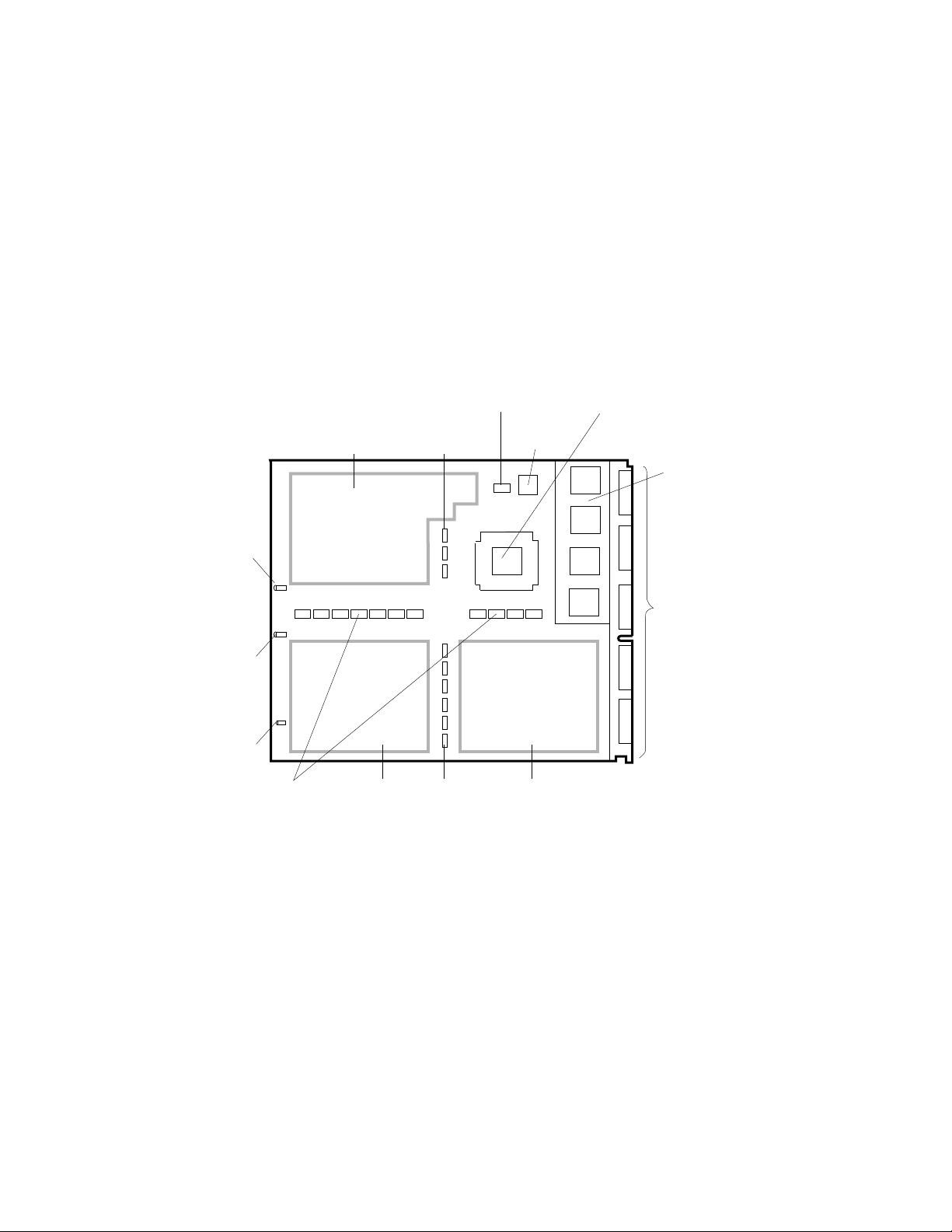
1.1 MS65A Description
The MS65A memory module is a metal-oxide semiconductor
(MOS), dynamic random access memory (DRAM), which
provides up to 128 Mbytes of data storage. The memory
module is designed for use with the VAX 6000 through the
XMI bus.
Figure 1–1: MS65A Module
GREEN
POWER
LED
YELLOW
SELF-TEST
LED
SMALL
RED
LED
CONTROL/ADDRESS
DRAM
BUFFERS
BLOCK STATE
BUFFER
DRAMS
DRAMS DRAMS
DATA
MUXs
DATA
MUXs
EEPROM
MEMORY CONTROL
GATE ARRAY
ZIF
CONNECTOR
SEGMENTS
msb-0454A-90
XMI
CORNER
1–2 VAX 6000: Installing MS65A Memories
Page 13

The MS65A memory module has the following features:
• The memory module contains MOS dynamic RAM (DRAM) arrays; a
CMOS memory control gate array that contains error correction code
(ECC) logic and control logic; an EEPROM storage element; and an
XMI interface known as the XMI Corner.
• Storage arrays are made up of two or four banks, either 155 or 299
DRAMs.
• ECC logic detects single-bit and double-bit errors and corrects single-bit
errors on 64-bit words.
• Memory self-test checks all RAMs, the data path, and control logic on
power-up.
• Quadwords, octawords, and hexwords can be read from or written to
memory.
• Memory is configured by the console program for 2-, 4-, 8-way or no
interleaving.
NOTE: The MS65A memory is required by VAX 6000 Model 500 and later
models since it implements the write-back cache protocol. However, it can
be used in Model 200, 300, and 400 systems.
Overview 1–3
Page 14

1.2 Required ROM Upgrades
VAX 6000 Models 200, 300, and 400 require CPU console and
diagnostic ROMs at correct revision levels to use MS65A
memory modules.
Example 1–1: Checking ROM Levels
#123456789 0123456789 0123456789 01234567#
F E D C B A 9 8 7 6 5 4 3 2 1 0 NODE #
A . . . . M M M . . P P P P TYP
o . . . . + + + . . + + + + STF
. . . . . . . . . . E E E B BPD
. . . . . . . . . . + + + + ETF
. . . . . . . . . . E E E B BPD
. . . . . . . . . + . + . + + . XBI D +
. . . . . . . . . + . + . + + . XBI E +
. . . . . A2 A2 A1 . . . . . . ILV
. . . . . 32 32 64 . . . . . . 128 Mb
2
ROM0 = V3.00
?2D For Secondary Processor 3
?52 ROM revision mismatch. Secondary processor has revision 2.0
?2D For Secondary Processor 3
?54 EEPROM revision mismatch. Secondary processor has revision 2.03/2.01
?2D For Secondary Processor 4
?52 ROM revision mismatch. Secondary processor has revision 1.0
?2D For Secondary Processor 4
?54 EEPROM revision mismatch. Secondary processor has revision 1.00/1.00
?2D For Secondary Processor 4
?56 Console parameters on secondary processor do not match primary
ROM1 = V3.00
2
EEPROM = 2.03/3.00 SN = SG01234567#
3
1
1–4 VAX 6000: Installing MS65A Memories
Page 15

Table 1–1: Minimum ROM Level Required
Model 200 V5.0
Model 300 V6.0
Model 400 V3.00
Model 500 V2.00
NOTE: Without the correct console ROMs, the system may crash and battery
backup will not work correctly.
Before you install the MS65A memory modules, compare the ROM version
with the required version shown in Table 1–1. Example 1–1 shows a Model
400 system with 128 Mbytes of memory.
You can check the ROM level on the last line of the self-test display on each
processor module. Power up the system or issue an INITIALIZE command
to run self-test.
1
This example is from a Model 400 system. The progress trace line does
not appear for Models 200 and 300.
2
The ROM information appears in this format for a VAX 6000 Model
400. Examine the ROM version numbers at2.
The ROM information appears in the following format for VAX 6000
Models 200 and 300:
ROM = 6.0 EEPROM = 2.0/6.0 SN = SG01234567
3
These are examples of ROM revision mismatch messages indicating
that the CPU modules have different ROM versions. The ROMs need
to be updated so that the versions are all the same. Refer to Appendix A
for ROM kit order numbers for the ROMs specific to your system.
Overview 1–5
Page 16

1.3 MS65A Configurations
MS62A memory modules cannot be used in VAX 6000 Model
500 systems. MS62A and MS65A memory modules can be
mixed in earlier models. (Figure 1–2 shows the order of
placement of MS65A modules in the XMI backplane.)
Figure 1–2: MS65A Configuration
XMI CARD CAGE
E D C B A 9 8 7 6 5 4 3 2 1
2
Memory Slots
1
msb-0133E-90
1–6 VAX 6000: Installing MS65A Memories
Page 17

Table 1–2: Memory Module Mixing
System MS65A MS62A
Model 500 Yes No No
Model 400 Yes Yes Yes
Model 300 Yes Yes Yes
Model 200 Yes Yes Yes
If an MS65A memory module or a mix of memory modules is used in Model
200, 300, or 400 systems, ROMs must be upgraded. The console and
diagnostic ROMS on the processor modules are replaced so that MS65A
memory modules are supported.
Memory ROM-based diagnostics function with both types of memory
modules. However, the ROM-based diagnostic does not test functions of
the EEPROM on the MS65A memory module on VAX 6000 Models 200,
300, and 400.
Memory modules are configured after I/O adapter and processor modules.
Install memory modules next to vector processors first, then install
additional memories as follows:
1
Install the first memory module in slot 9. Fill all available slots left to
right from slot 9 to slot 2.
Both MS65A
and MS62A
2
Install any additional memory modules right to left in available slots
from slot A to slot D.
NOTE: VAX 6000 systems with FV64A vector modules are an exception to
these configuration rules. Memory is first installed to the left of each vector
processor module, since only memory modules are permitted in these slots.
Overview 1–7
Page 18

1–8 VAX 6000: Installing MS65A Memories
Page 19

Chapter 2
Unpacking and Installation
This chapter discusses the unpacking and installation procedures for the
MS65A memory module. Sections include:
• Unpacking and Inspection Procedures
• Memory Installation in Systems Without a Vector Processor
• Memory Installation in Systems with a Vector Processor
Unpacking and Installation 2–1
Page 20

2.1 Unpacking and Inspection Procedures
MS65A memory modules are shipped in special packing
cases to ensure maximum protection for each module. Each
module should be inspected before installation.
Table 2–1: MS65A Memory Modules
Option Number Module Number Memory Size (Mbytes)
MS65A-BA T2053-BA 32
MS65A-CA T2053-CA 64
MS65A-DA T2053-DA 128
2–2 VAX 6000: Installing MS65A Memories
Page 21

CAUTION: The MS65A module is static sensitive. ESD precautions must
be taken when handling the module outside of its protective case. Use an
antistatic wrist strap when handling the module. Use a Velostat Kit (CD kit
number A2-W0299-10) to lay the modules on if many modules are removed
and installed.
The MS65A memory module is shipped in a special electrostatic discharge
(ESD) case to protect it from mechanical shock, electrical shock, and
vibration.
MS65A memory modules are available in three sizes. Table 2–1 lists the
three MS65A memory modules.
To unpack and inspect the memory module, do the following:
1. Put the antistatic wrist strap on.
2. Open the case and remove any packing materials.
3. Visually inspect the module for any damage such as bent pins.
Unpacking and Installation 2–3
Page 22

2.2 Memory Installation in Systems Without a
Vector Processor
Before adding memory modules, check the interleave set.
If the default interleave is not being used, return the
system to the default, so that new memory modules will be
interleaved by the system. Install new memory modules in
the appropriate slots. Refer to the configuration rules in
Section 1.3.
Example 2–1: Existing Memory Interleave
>>> SHOW MEMORY ! Displays the memory lines from the
F E D C B A 9 8 7 6 5 4 3 2 1 0 NODE #
. . . . B1 A1 . . . . . . . . ILV
. . . . 32 32 . . . . . . . . 64 Mb
/INTERLEAVE:(9, A)
>>> SET MEMORY /INTERLEAVE:DEFAULT ! Command to cancel any previous
! system self-test
! interleave instruction
Example 2–2: Default Memory Interleave with MS65A Installed
#123456789 0123456789 0123456789 01234567#
F E D C B A 9 8 7 6 5 4 3 2 1 0 NODE #
A A . . M M M . . . P P P P TYP
o o . . + + + . . . + + + + STF
. . . . . . . . . . E E E B BPD
. . . . . . . . . . + + + + ETF
. . . . . . . . . . E E E B BPD
. . . . . . . . . + . + + . + . XBI D +
. . . . . . . . . + . + . + + . XBI E +
. . . . A2 A2 A1 . . . . . . . ILV
. . . . 32 32 64 . . . . . . . 128 Mb
ROM0 = V3.00 ROM1 = V3.00 EEPROM = 2.03/3.00 SN = SG01234567
2–4 VAX 6000: Installing MS65A Memories
Page 23

Before you add memory modules to a system, check to see that the system
is set to the default interleave (see Example 2–1). If the interleave is
not set to default, record the current setting and then set interleaving
to default. Default interleaving is recommended because it provides the
optimum memory configuration. See Appendix B for information on how
the console program interleaves memory.
To add memory modules, perform the following steps:
1. Perform an orderly shutdown of the system.
2. Turn the upper key switch on the front control panel to the Off position.
3. Open the front cabinet door.
4. Remove the clear plastic door in front of the XMI cage.
CAUTION: You must wear an antistatic wrist strap attached to the
cabinet when you handle any modules.
5. Install memory modules in slots adjacent to existing memory modules
Hold the lever up until the module is in place and then press the lever
down to close the connectors.
6. Replace the clear door.
7. Follow the power-up and self-test procedure in Chapter 3.
In Example 2–2 one 64-Mbyte memory module was added to a Model 400
system. By convention (for a VAX 6000 Model 400), memory begins at slot
A and expands to the right, so the new module is inserted in slot 8.
Unpacking and Installation 2–5
Page 24

2.3 Memory Installation in Systems with a Vector
Processor
Memory installation in a VAX 6000 Model 400 or later
system with the FV64A vector processor requires a special
configuration. Install new memory modules in the
appropriate slots.
Example 2–3: MS65A Installed in a Vector System
#123456789 0123456789 0123456789 0123456789 0123456789 01234567#
F E D C B A 9 8 7 6 5 4 3 2 1 0 NODE #
A A . . . M M M M V- -P M V- -P TYP
+ + . . . + + + + + + + + + STF
. . . . . . . . . E E . E B BPD
. . . . . . . . . + + + + + ETF
. . . . . . . . . E E . E B BPD
. . . . . A3 A2 A1 A4 . . A4 . . ILV
. . . . . 64 64 64 32 . . 32 . . 256 Mb
CONSOLE = V2.00 RBDs = V2.00 EEPROM = 2.03/2.00 SN = SG01234567
>>>
2–6 VAX 6000: Installing MS65A Memories
Page 25

Before you add memory modules to a system, the system must be set to the
default interleave. In a system with vector processors, memory modules
are first installed to the left of the FV64A vector modules.
To add memory modules, perform the following steps:
1. Perform an orderly shutdown of the system.
2. Turn the upper key switch on the front control panel to the Off position.
3. Open the front cabinet door.
4. Remove the clear plastic door in front of the XMI cage.
CAUTION: You must wear an antistatic wrist strap attached to the
cabinet when you handle any modules.
5. Install memory modules in the appropriate slots. Hold the lever up
until the module is in place and then press the lever down to close the
connectors.
6. Replace the clear door.
7. Follow the power-up and self-test procedure in Chapter 3.
In Example 2–3 three more memory modules were added to a Model 500
system. Memory begins at slot 9 and expands to the right, so the three new
modules were inserted in slots 9, 8, and 7.
Unpacking and Installation 2–7
Page 26

2–8 VAX 6000: Installing MS65A Memories
Page 27

Chapter 3
Power-Up and Self-Test
This chapter provides the power-up procedure and explains the operation
of self-test and self-test errors.
• Power-Up
• Self-Test Errors
Power-Up and Self-Test 3–1
Page 28

3.1 Power-Up
Power up the system and check the self-test display for
the new memory modules. Check the interleaving and any
error messages. The self-test display shows that the console
program configured the additional memory into the system.
Example 3–1: Model 500 Power-Up
#123456789 0123456789 0123456789 0123456789 012345#
F E D C B A 9 8 7 6 5 4 3 2 1 0 NODE #
A A . . M M M . . . P P P P TYP
+ + . . + + + . . . + + + + STF
. . . . . . . . . . E E E B BPD
. . . . . . . . . . + + + + ETF
. . . . . . . . . . E E E B BPD
. . . . A2 A2 A1 . . . . . . . ILV
. . . . 32 32 64 . . . . . . . 128 Mb
CONSOLE = V2.00 RBDs = V=2.00 EEPROM = 2.00/2.00 SN = SG01234567
4
>>>
1
2
3
3–2 VAX 6000: Installing MS65A Memories
Page 29

Power up the system by turning the lower key switch to Halt and the upper
key switch to Enable.
Check the self-test display as follows:
1
The memory modules are indicated by an M on the TYP line, as shown
in Example 3–1. The memory module in slot 8 has been added.
2
All three memories passed self-test, as indicated by plus signs (+) on
the STF line.
3
All memories are represented on the ILV line; in this case all three are
in one interleave set (the default).
4
No error messages are displayed. Error messages are listed in the VAX
6000 Series Owner’s Manual.
Power-Up and Self-Test 3–3
Page 30

3.2 Self-Test Errors
If an MS65A memory module fails self-test, the console
runs an explicit memory test on the failing module. Any
console error messages are displayed. The failing module is
included in the memory configuration. Example 3–2 shows
how a failing memory module can be excluded from the
configuration.
Example 3–2: MS65A Memory Module Exclusion
>>> INITIALIZE
#123456789 0123456789 0123456789 01234567#
F E D C B A 9 8 7 6 5 4 3 2 1 0 NODE #
A A . . M M M M . . P P P P TYP
o o . . - + + + . . + + + + STF
. . . . . . . . . . E E E B BPD
. . . . . . . . . . + + + + ETF
. . . . . . . . . . E E E B BPD
. . . . . . . . . + . + + . + . XBI D +
. . . . . . . . . + . + . + + . XBI E +
. . . . C1 B1 A2 A1 . . . . . . ILV
. . . . 32 32 64 64 . . . . . . 192 Mb
ROM0 = V3.00 ROM1 = V3.00 EEPROM = 2.03/3.00 SN = SG01234567
>>> SET MEMORY /INTERLEAVE:(7+9, 8)
If an MS65A node fails self-test, as indicated by a – in the STF line,
the console executes an explicit memory test during the building of the
bitmap. The failing memory module is included in the configuration, but
the addresses that failed self-test are not used. Since the memory at node
A failed self-test, it would be included in the configuration, but would
not interleaved with node 9. Use the SET MEMORY command without
designating the node you want to exclude.
During the explicit memory test, a number of console messages might
be displayed to aid in diagnosing the problem. Console error messages
pertaining to memory are shown in Table 3–1.
3–4 VAX 6000: Installing MS65A Memories
Page 31

Table 3–1: Console Error Messages for Memory (Models 400 and
500)
Error Message Meaning
?0037 Explicit interleave list is
bad. Configuring all arrays uninterleaved.
?0046 Memory interleave set is
inconsistent: n n ...
?0047 Insufficent working memory for normal operation.
?0048 Uncorrectable memory
errors—long memory test must
be performed.
?004A Memories not interleaved
due to uncorrectable errors:
The list of memory arrays for explicit interleave includes no nodes that are actually memory arrays. All arrays found in the system are configured.
The listed nodes do not form a valid memory interleave
set. One or more of the nodes might not be a memory array or might be of a different size, or the set could contain an invalid number of members. Each listed array that is a valid memory will be configured uninterleaved.
Less than 256 Kbytes per processor of working memory were found. There is insufficient memory for the console to function normally or for the operating system to boot.
A Model 400 memory array contains an unrecoverable error. The console must perform a slow test to locate all the failing locations.
The listed arrays would normally have been interleaved (by default or explicit request). Because one or
more of them contained unrecoverable errors, this interleave set will not be constructed.
When all testing is done, the yellow self-test LED on the memory module
indicates only that the self-test has completed. After self-test, starting and
ending addresses are set by the boot processor.
NOTE: If self-test fails, see the VAX 6000 Model 500 Service Manual and
the VAX 6000 Model 300 and 400 Service Manual.
Power-Up and Self-Test 3–5
Page 32

3–6 VAX 6000: Installing MS65A Memories
Page 33

Appendix A
ROM Kit Order Numbers
This appendix lists the ROM kit order numbers to upgrade VAX Models
200, 300, and 400 systems to support MS65A memory modules. ROM
replacement instructions are included in each ROM kit.
Table A–1: ROM Kit Numbers
System
Model 200 V5.0 or later Model 210 62X00-AA
Model 300 V6.0 or later Model 310 63X00–AA
Required
ROM Level Model
Model 220 62X00–AB
Model 230 62X00–AC
Model 240 62X00–AD
Model 320 63X00–AB
Model 330 63X00–AC
Model 340 63X00–AD
Model 350 63X00–AE
Model 360 63X00–AF
VAXserver 310 63X00–BA
VAXserver 320 63X00–BB
ROM Kit
Number
Model 400 V3.00 or later Model 410 64X00–AA
Model 420 64X00–AB
Model 430 64X00–AC
Model 440 64X00–AD
ROM Kit Order Numbers A–1
Page 34

Table A–1 (Cont.): ROM Kit Numbers
System
Model 500 No ROM change is required.
Required
ROM Level Model
Model 450 64X00–AE
Model 460 64X00–AF
VAXserver 410 64X00–BA
VAXserver 420 64X00–BB
ROM Kit
Number
A–2 VAX 6000: Installing MS65A Memories
Page 35

Appendix B
Interleaving
Interleaving optimizes memory access time and is automatically performed
by the console program. Console commands associated with interleaving
can be used to interleave memories, but this is not recommended.
This appendix contains the following information on interleaving:
• Overview
• Console Commands
Interleaving B–1
Page 36

B.1 Overview
Memory supports 2-, 4-, 8-way or no interleaving. Up to
eight memory modules can be interleaved. Memory should
be interleaved by using the default interleave rather than
with console commands.
Figure B–1: MS65A Interleaving
32 Mb
2-WAY INTERLEAVE SET
32 Mb
(32, 32)
32 Mb
32 Mb
2-WAY INTERLEAVE SET
(32 + 32, 64)
64 Mb
128 Mb
128 Mb 128 Mb
32 Mb
32 Mb
4-WAY INTERLEAVE SET WITH ONE MEMORY NOT INTERLEAVED
(128, 128, 128, 64 + 32+32) interleaved and (32) not interleaved
64 Mb
32 Mb
msb-0717A-91
B–2 VAX 6000: Installing MS65A Memories
Page 37

Figure B–1 shows three examples of interleaving. The first is a two-way
set (32, 32); two arrays of the same size are interleaved. The second twoway set (32 + 32, 64) consists of different size arrays. At the bottom of
Figure B–1 is a system with a a four-way set made up of six modules and
one 32 Mbyte module that is not interleaved.
When different sizes of memory modules are installed, the console
interleaves the memory modules according to size and sets as follows:
• Sorts memory modules into groups by size.
• Interleaves the largest size memory modules first.
• Stacks remaining sets of modules into sets that equal the largest size
memory modules and interleaves them with the largest size memory
modules.
• Stacks remaining modules into sets of the next largest size memory
modules and interleaves them.
• Continues stacking and interleaving memory modules until all memory
modules have been configured (including noninterleaved modules).
NOTE: Memory modules that fail self-test due to multiple bit errors are not
included in an interleave set.
Interleaving B–3
Page 38

B.2 Console Commands
The SET MEMORY command is used for setting the
interleave to a memory configuration other than the
default interleave. The SET MEMORY command does not
change memory interleaving; it just modifies the memory
configuration in the EEPROM.
NOTE: It is not advisable to use console commands to interleave memory
modules, but occasional customer use will warrant overriding the original
console setting of the interleave.
Example B–1: SET MEMORY and SHOW MEMORY Commands
>>> SET MEMORY /INTERLEAVE:DEFAULT
>>> SHOW MEMORY
F E D C B A 9 8 7 6 5 4 3 2 1 0 NODE #
. . . . A2 A2 A1 . . . . . . . ILV
. . . . 32 32 64 . . . . . . . 128 Mb
/INTERLEAVE:DEFAULT
>>> SET MEMORY /INTERLEAVE:(8, 9+A)
>>> INITIALIZE
>>> SHOW MEMORY
F E D C B A 9 8 7 6 5 4 3 2 1 0 NODE #
. . . . B2 B1 A1 . . . . . . . ILV
. . . . 32 32 64 . . . . . . . 128 Mb
/INTERLEAVE:(8, 9+A)
>>>
2
4
5
! For a system with one 64-Mbyte and two
! 32-Mbyte memory modules, interleaving
! creates two sets of 64-Mbyte memories
! (1x64-Mbyte memory and 2x32-Mbyte memory)
! located at XMI nodes A, 9, and 8.
! Displays the memory lines from self-test.
! The user explicitly specifies
! the interleave sets (two interleave
! sets with modules in nodes 8, 9, and A).
! Initializes the system.
! Displays the memory lines from self-test.
1
3
B–4 VAX 6000: Installing MS65A Memories
Page 39

The callouts in Example B–1 are explained below.
1
The SET MEMORY command (as shown here) returns the system to
the default interleaving configuration.
2
The SHOW MEMORY command displays the node number (node #),
interleave (ILV), and total usable memory (xxMb) lines from the selftest results.
3
This SET MEMORY command creates a 2-way interleave. In this
example the user explicitly specifies how to interleave the memory
modules. Each interleaving set must contain the node number of the
memory module. If more than one memory module is in a set, they are
joined by a + sign. Each set of interleaved memory modules must be
separated by a comma.
4
The system is initialized to put the new memory interleave into effect.
5
The SHOW MEMORY command displays the configuration set in3.
NOTE: Refer to Chapter 5 of the VAX 6000 Series Owner’s Manual
for detailed information on the SET MEMORY and SHOW MEMORY
commands.
Interleaving B–5
Page 40

Index
C
Configuration rules
mixed memory, 1–1, 1–7
without vectors, 1–7, 2–5
with vectors, 1–7, 2–7
Console commands
for interleaving, B–4 to B–5
INITIALIZE, 1–5, B–4
SET MEMORY, 2–4, 2–6, 3–4,
B–4
SHOW MEMORY, 2–4, 2–6, B–4
Console error messages, 3–5
Console parameters
mismatch, 1–4
D
DRAMs, 1–3
E
ECC logic, 1–3
EEPROM, 1–3, 1–7
revision mismatch, 1–4
Error messages, 3–3
ESD precautions, 2–2
I
INITIALIZE command, 1–5, B–4
Installation
adding memory, 2–4
power-up, 3–3
with vectors, 2–6
Interleaving, B–1 to B–5
checking the set, 2–4, 3–3
console commands, B–4
default, 2–4, 2–5, B–2
Interleaving (Cont.)
existing memory, 2–4
memory module sets, B–3
M
Module types, 2–2
P
Power-up, 3–2
R
ROM-based diagnostics, 1–7
ROM kit order numbers, A–1
ROM levels
checking, 1–4
revision mismatch, 1–4
ROM upgrades, 1–4, 1–7
incorrect ROMs, 1–4
revision mismatch, 1–4
ROM kits, 1–5, A–1
ROM levels, 1–5
S
Self-test, 1–4
console error messages, 3–4
errors, 3–4
failure, 3–4
memory module exclusion, 3–4
memory module failures, B–3
progress trace line, 1–5
yellow LED, 3–5
SET MEMORY command, 2–4, 2–6,
3–4, B–4
SHOW MEMORY command, 2–4,
2–6, B–4
Index–1
Page 41

System expansion, 1–3
U
Unpacking and inspection, 2–2
V
Velostat kit, 2–2
W
Write-back cache protocol, 1–3
Index–2
 Loading...