

Digital Equipment 3220 Series, 3220R Series Installation Manual

DIGITAL™ Server 3220/3220R Series
Installation Guide
Installationshandbuch
Guía de instalación
Guide d’installation
Guida di installazione
™
DIGITAL Server 3220/3220R Series2
hank ou
... for purchasing a DIGITAL Server 3220/3220R.
The DIGITAL Server family represents DIGITAL’s
continued commitment to Uncompromising
Quality, backed by award-winning Customer
Service and Support. The following procedures
will help you easily set up your server’s
hardware and software.
Before You Begin
Select a suitable area for server and rack assembly and
use. Ensure that the location:
■ Is free from excessive heat, dust, and direct sunlight
■ Allows at least 30 inches of clearance at the rear of
the rack and 60 inches at the front of the rack for
rack models
■ Allows at least 7 inches of clearance on all sides for
proper air flow around pedestal models
■ Is in accordance with local and regional electrical
regulations governing the installation of Information
Technology Equipment by licensed electricians
See “Technical Specifications” in your System Reference
manual for temperature and humidity information.
If you do not wish to install the server yourself, contact
your DIGITAL authorized service provider. A Customer
Service Technician can install the server for you.
WARNING
Use extreme care when unpacking your server.
Due to its weight, two people are required to
unpack it. Failure to use two people might violate
certain safety regulations and can result in severe
personal injury or equipment damage.
YT
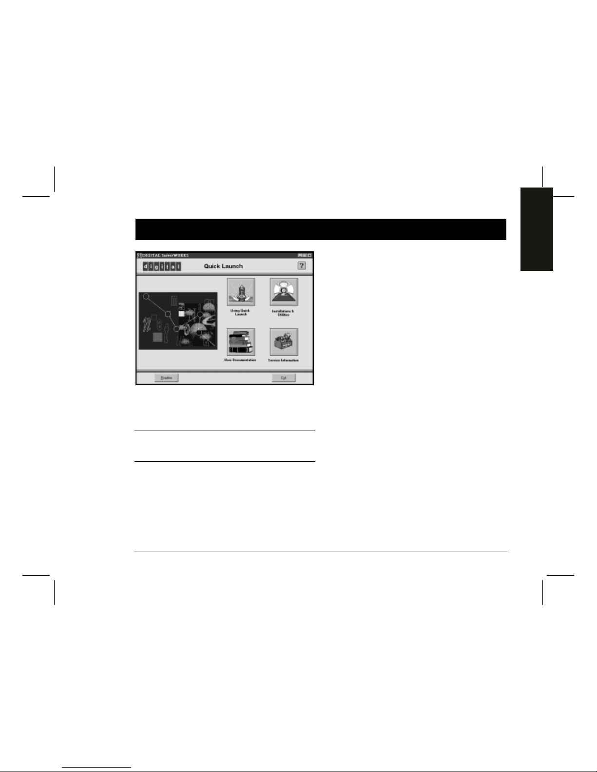
DIGITAL ServerWORKS Quick Launch
DIGITAL ServerWORKS Quick Launch delivers
unparalleled achievement in streamlining the installation and configuration of hardware components
and network operating system software on the
DIGITAL Server line of products. Quick Launch
combines an intuitive interface and versatile, time
saving features to produce a consistent and accurate
installation optimized for DIGITAL’s extremely powerful and highly acclaimed DIGITAL Servers.
In addition to its automated yet extensible method
of express installations for Network Operating
Systems, Quick Launch provides a comprehensive
archive of server documentation, troubleshooting
assistance, configuration utilities, and diagnostics.
Installation Guide
3
ENGLISH
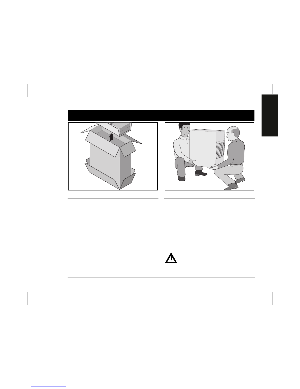
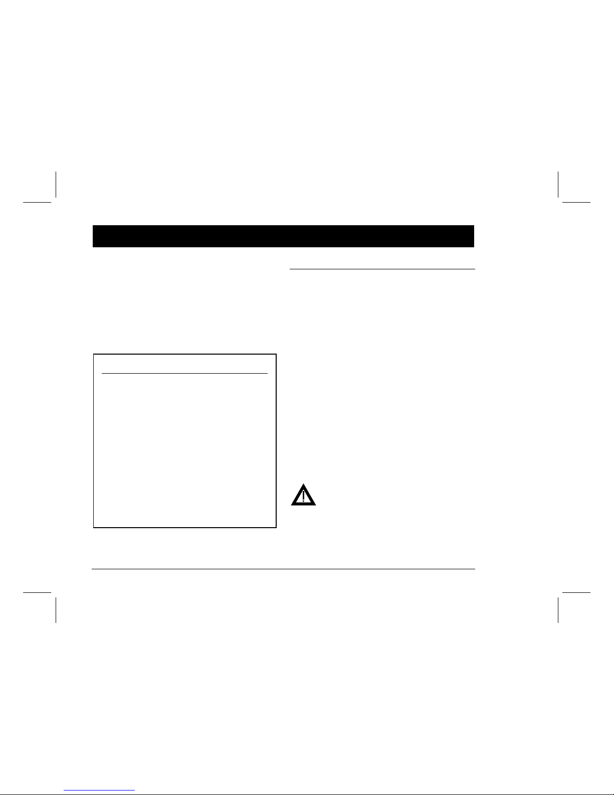
Unpack your server
Unpacking Instructions
Pedestal Model (shown above)
1. Tip the box on its side. Open the bottom of the box
and fold the bottom flap under the box.
2. While still in the box, set the server upright.
3. Open the top of the box and remove the country kit.
4. Close the top of the box. Using the handles on the box,
remove it from the top of the server.
5. Move the server to your desired location. Tip the
server slightly and rotate the four pedestal feet outward until they lock into position.
Rackmount Model
Unpack your server following the diagrams on the box
top. Use a mechanical aid or get someone to help you lift
it from the carton base.
If you need to lift the server…
1. Get close to the server.
2. Squat down with your knees bent and your feet apart
for stable footing.
3. Lift with your legs, keeping your back straight.
4. Avoid twisting your upper body. Move your feet to turn.
5. Lower the server gently using your leg muscles to squat
while keeping your back straight.
After your server has been unpacked, please recycle the
packing materials or dispose of them properly.
WARNING
The server is heavy. Do not lift it alone.
1
DIGITAL Server 3220/3220R Series4
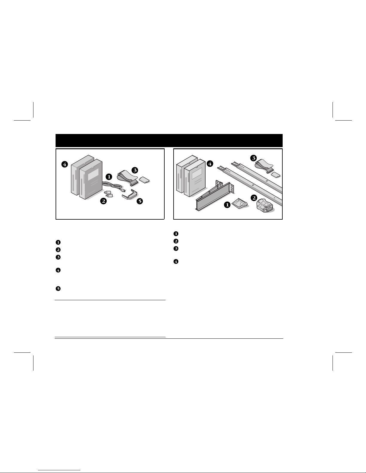
Check the parts
Unpack and identify your server’s components.
Pedestal Model
Power cord
Server keys
Optional 68-pin SCSI cable for connecting the
SCSI channel 2 to an exterior port and terminator
Server software and documentation kits including
printed manuals and the Quick Launch CD-ROM with
on-line documentation
Hot swap drive extraction tool
NOTE
A rack, monitor, and a country kit including a keyboard,
keyboard extension cable, and mouse must be ordered
separately for either server model.
A power cord is included in the country kit for the pedestal model but must be ordered separately for the rackmount model.
Rackmount Model
Cable management arm and brackets
Slides (2) and mounting hardware
Optional 68-pin SCSI cable for connecting the
SCSI channel 2 to an exterior port
Server software and documentation kits including
printed manuals and the Quick Launch CD-ROM with
on-line documentation
The DIGITAL ServerWORKS software kit includes:
■ ServerWORKS Quick Launch: ServerWORKS Quick
Launch CD-ROM software and
Getting Started
guide.
■ ServerWORKS Manager kit: ServerWORKS Manager
software and documentation.
The DIGITAL Server Documentation kit includes:
■ This
Installation Guide, System Reference
manual,
Documentation Overview, Warranty and Service
Information,
and
Registration Card.
2
Installation Guide
5
ENGLISH
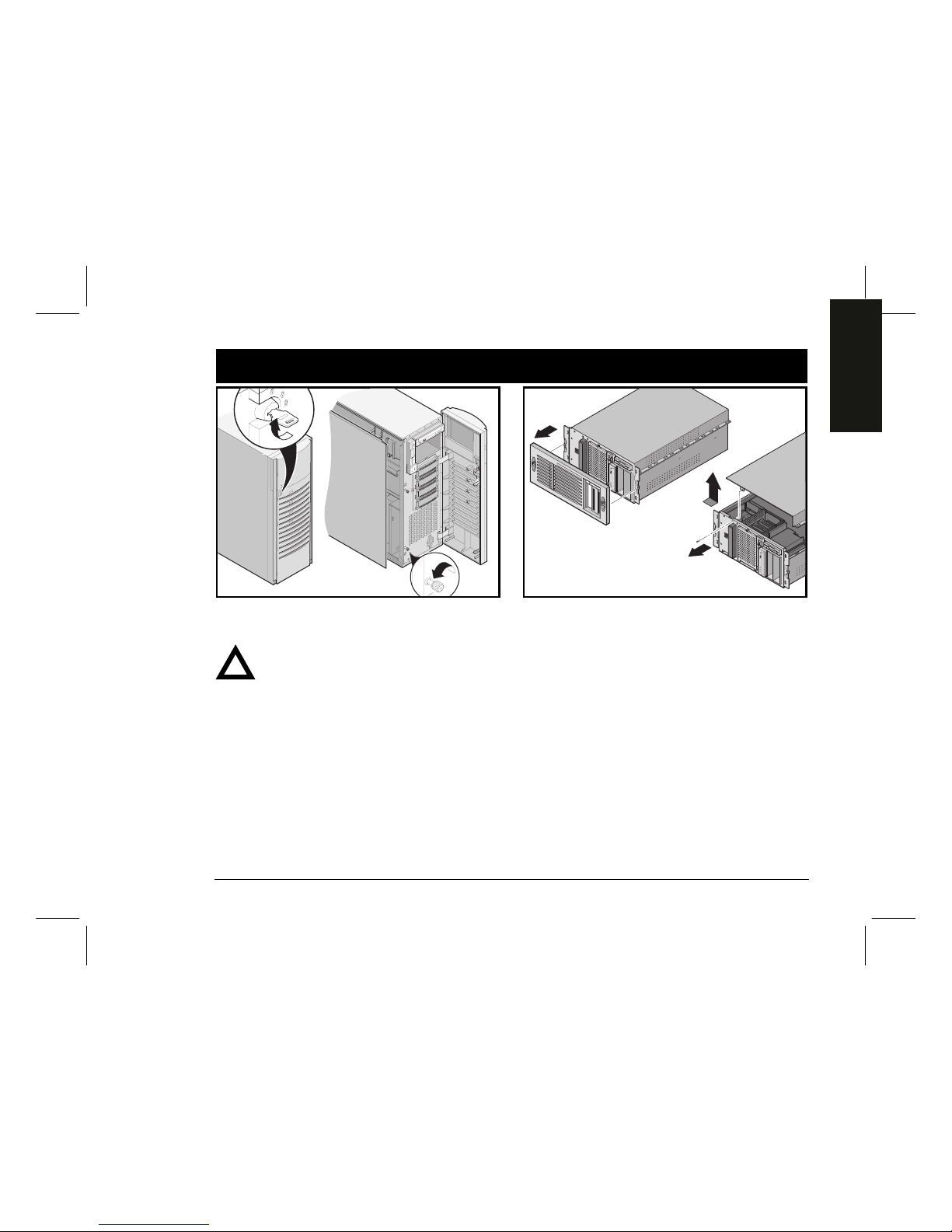
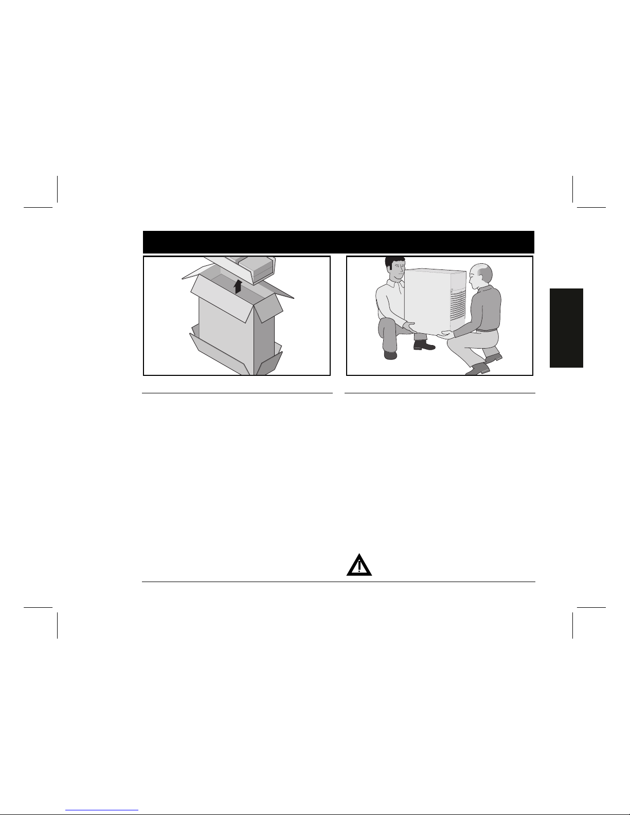
Install any internal options
If you have options to install, install them now. To install
internal options:
CAUTION
Before touching any circuit board or component,
wear an anti-static wrist strap, properly grounded
to the server chassis, or touch the metal frame to
discharge any static electricity.
Pedestal Model
1. Unlock the door and front bezel.
2. Open the front bezel and loosen the two
side panel thumbscrews.
3. Remove the side panel.
4. Install the options.
Rackmount Model
1. Remove the front bezel.
2. Remove the screw and then remove the top cover.
3. Install the options.
Refer to the
System Reference
manual for detailed information. Also, refer to the documentation that came with
the option kit for specific installation instructions.
3
DIGITAL Server 3220/3220R Series6
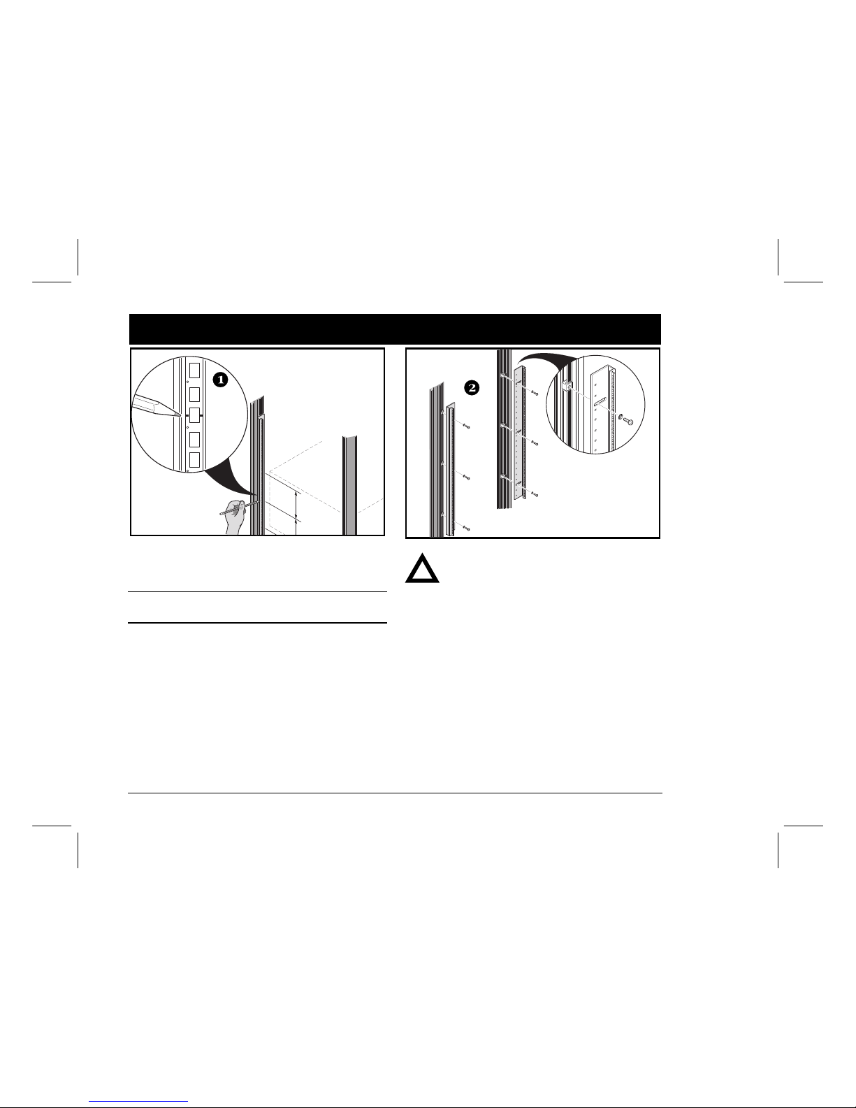
Install your server in the rack (3220R only)
1. Mark the installation area. Allow 128 cm (50 in.) for
installation.
NOTE
On a DIGITAL rackmount, each 14U rail is marked at 1U
increments.
2. If needed, attach the mounting angles to the rack.
CAUTION
Mounting angles must be tightened to a torque
value of 4.2 N-m (3.1 ft-lbs).
4
Installation Guide
7
ENGLISH
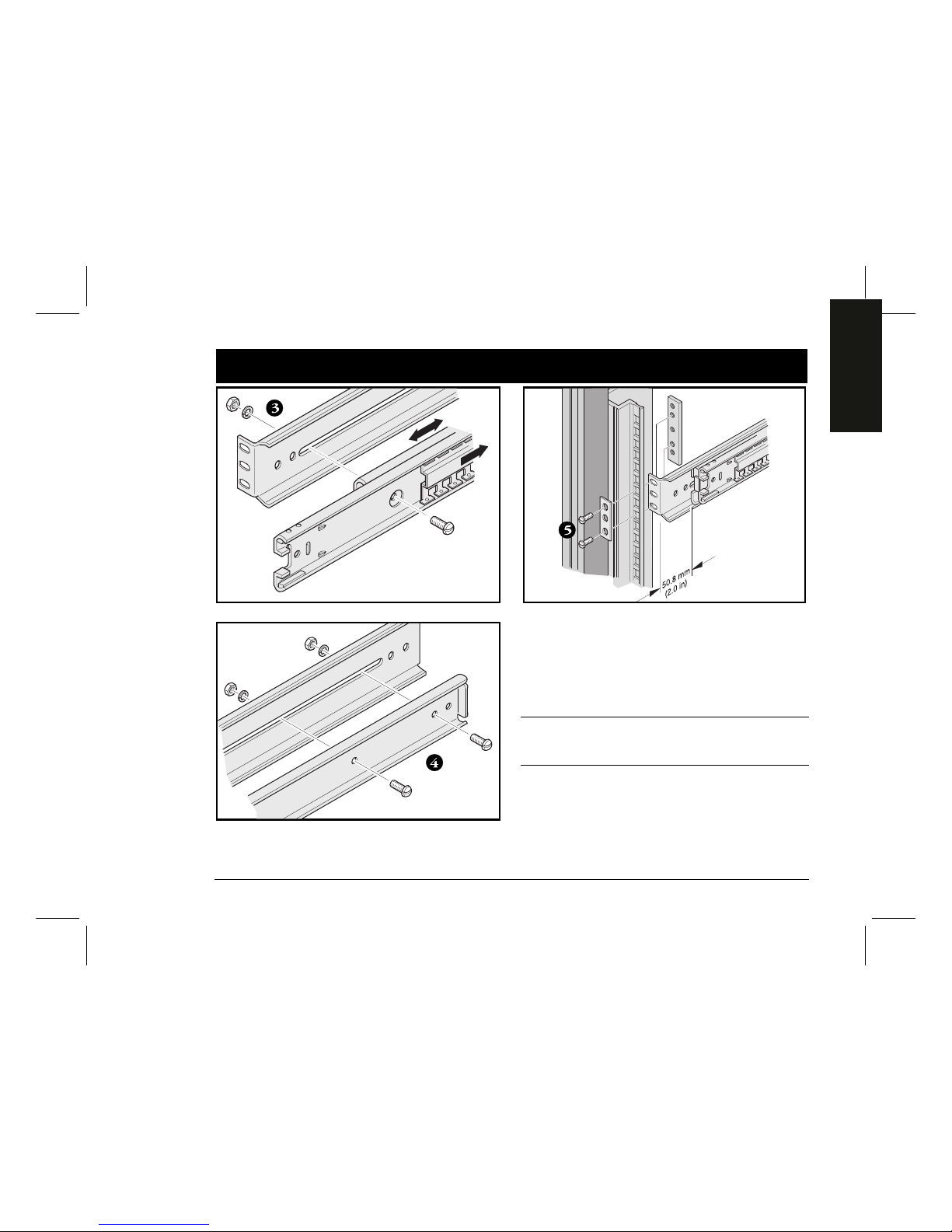
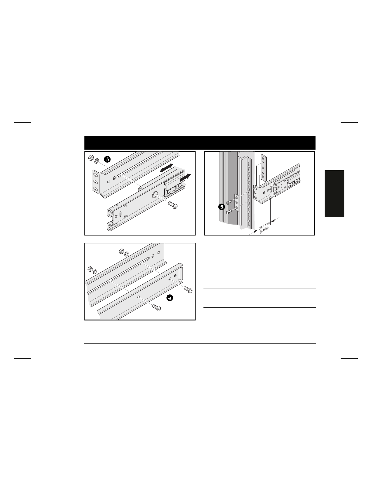
Rack installation continued
3. Assemble the front of the slide mounting brackets
(front view).
4. Assemble the back of the slide mounting brackets.
5. Attach the slide mounting brackets to the rack.
NOTE
On a DIGITAL rackmount, the chassis slide must be fastened 50.8 mm (2 in.) behind the front rail to ensure
proper door clearance.

DIGITAL Server 3220/3220R Series8
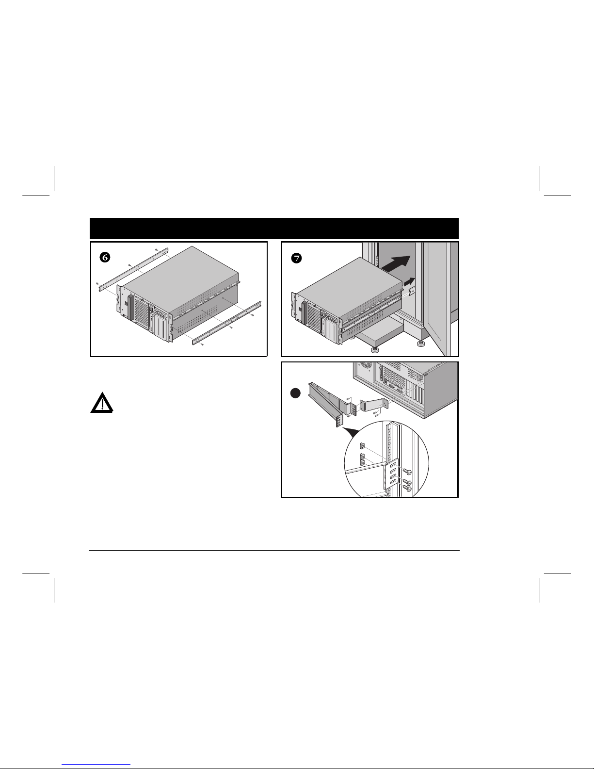
Rack installation continued
6. Attach the slide rails to the server.
7. Install the server into the rack.
WARNING
Use two people to lift the server.
8. Attach the cable management arm.
8
Installation Guide
9
ENGLISH
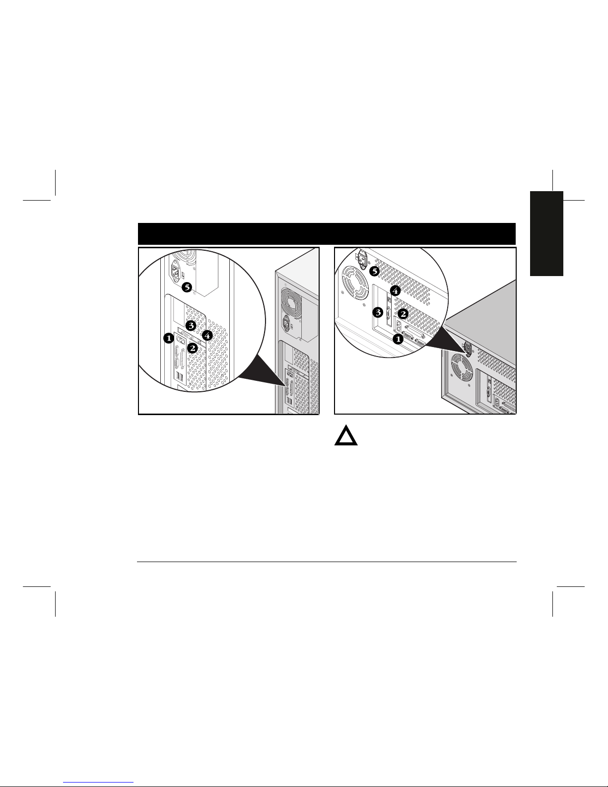
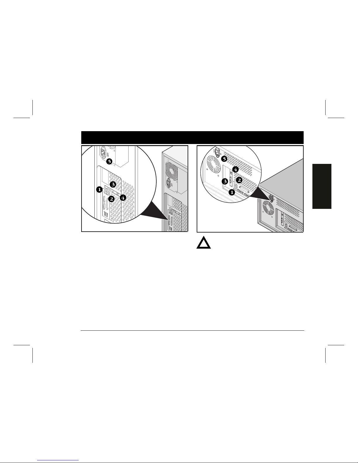
Connect the cables and power cord
1. Connect the keyboard.
2. Connect the mouse.
3. Connect the monitor.
4. Connect the 10/100Base-T network cable.
5. Connect ac power.
For more information on connecting server cables for the
model 3200R, refer to the DIGITAL Server Rackmount
Installation Guide.
CAUTION
The voltage selection switch must match the
voltage supplied by your power outlet. In North
America, 115 volts is common. In other countries,
230 volts is common. Ensure that the voltage
selection switch is set to the correct voltage. If it
is not set correctly, you can damage your server.
Do not attempt to modify or use an external
100 Vac (Japan only) or 115 Vac power cord for
240 Vac input power. Modifying either cord can
cause severe equipment damage.
5

DIGITAL Server 3220/3220R Series10
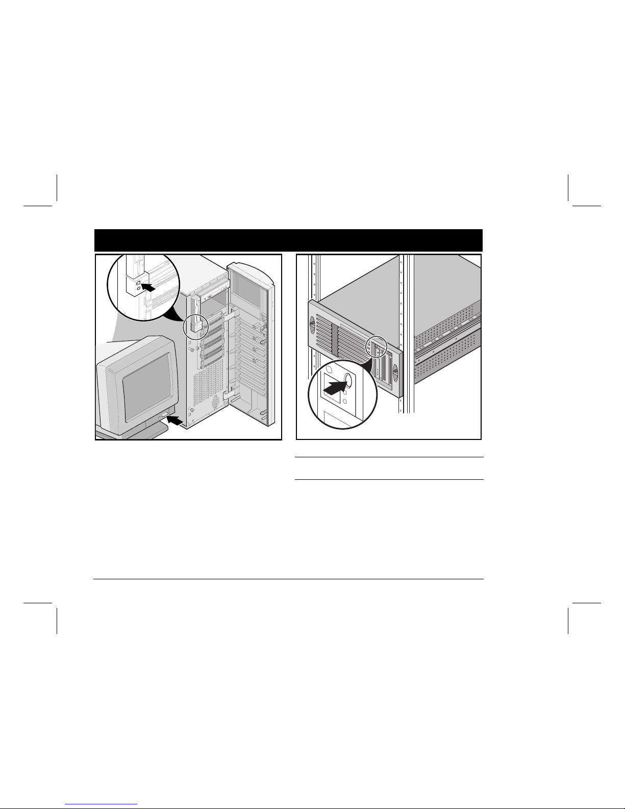
Turn on the monitor and then the server
1. Turn on the monitor.
2. Turn on the server.
3. Adjust the monitor’s contrast and brightness to obtain
a readable screen display.
NOTE
Refer to your System Reference manual for BIOS and
Power-On-Self-Test (POST) messages.
6

Installation Guide
11
ENGLISH
If you installed optional expansion boards
Your server was setup for normal operation at the factory
and will operate properly without additional configuration.
However, you may need to use one of the following utilities if you installed expansion boards:
■ BIOS Setup Utility
■ SCSI Configuration Utility
■ Mylex™ Configuration Utility for RAID
The default device scan sequence is also listed here.
Accessing the BIOS Setup Utility
Use the BIOS Setup Utility if you experience problems
with your hard disk or if you need to reconfigure your onboard controller or boot settings. To access the BIOS Setup
Utility, perform the following steps:
1. Turn on your server and allow the Power-On Self Test
(POST) to run.
2. During the boot process, note any configuration errors
listed. At the DIGITAL banner, press [F2] for Setup or
[F3] for System Management.
3. Follow the instructions on your monitor.
On-line help is available by pressing [F1]. Navigation keys
are displayed at the bottom of all menus.
Changing the Boot Device Priority
1. Access the BIOS Setup Utility [F2].
2. At the top of the Main menu, select Boot.
3. Select “Boot Device Priority” and press
[Enter].
4. Use the up and down arrow keys to select a device;
then use the + and – keys to move the selection up or
down:
1. ATAPI CD-ROM Drive
2. Diskette Drive
3. Hard Drive
5. To Save, press [Escape]. On the top screen menu, select
Exit. The screen displays the message “Save
configuration changes and exit
now.” Select Yes and press [Enter]. The system will
reboot and automatically save your changes.
Changing Conflicting IRQs
1. Access the BIOS System Management utility [F3] and
select <PCI> to check the status of the PCI IRQ assignments. Note any conflicts between IRQ settings.
2. If you need to change any IRQ settings or reserve an
IRQ for an ISA expansion board, reboot the server and
access the BIOS Setup Utility [F2].
3. Select Advanced at the top of the screen.
4. Select PCI Configuration and press [Enter].
5. Highlight the PCI IRQ line number to change
and press [Enter].
6. Use the + and – keys to select an available IRQ
number, auto select, or disabled. An as-
terisk (*) appears to the left of the line if the IRQ is in
use. After making a selection, press [Enter].
7. To reserve memory and an IRQ number for an ISA
expansion board, select the following menu items:
PCI/PNP ISA UMB Region Exclusion
PCI/PNP ISA IRQ Resource Exclusion
8. To Save, press [Escape]. On the top screen menu, select
Exit.
7
DIGITAL Server 3220/3220R Series12
Expansion boards continued
SCSI Configuration Utility
If a SCSI option has been added to your server, you may
run the SCSI Configuration Utility to configure the newly
added card(s) or disk drive(s).
Press Ctrl + C when prompted during the boot process to
run the SCSI Configuration Utility.
Refer to your System Reference manual for additional
information on this utility.
NOTE
If you installed SCSI cards, make sure that the MS-DOS
partition resides on the boot device. If not, shut down the
server, change the order of the cards and reconfigure your
server. Refer to the device scan sequence later on this
page.
Mylex Configuration Utility
If the server detects the presence of a Mylex™ RAID controller, the RAID utility is invoked. This utility allows you to
configure any newly installed RAID devices.
Device Scan Sequence
Devices are identified and initialized in the following
order:
■ IDE CD-ROM drive
■ Onboard SCSI controllers, Channel 1 then Channel 2
■ PCI slots 1–6
■ ISA slots 1 and 2
CAUTION
Changing some settings might cause your server
to operate improperly. It is important for you to
read carefully and understand the information
about BIOS setup in your System Reference
before attempting to modify the server’s factory
settings.
Installation Guide
13
ENGLISH
Run the Quick Launch CD-ROM program
Use the Quick Launch bootable CD-ROM disc to complete
the server installation. Follow these steps to configure your
DIGITAL Server and install an operating system.
NOTE
The minimum requirements to run Quick Launch are
16 MB of RAM, a hard disk drive, mouse, keyboard, monitor, network card and a CD-ROM drive.
1. Locate the Quick Launch bootable CD-ROM disc in your
DIGITAL ServerWORKS software kit. Power on your
server to boot from the CD-ROM.
2. Choose your language from the selections available.
3. When prompted, you can create an MS-DOS partition
size appropriate for your operating system. You are
prompted to confirm your choice. Note that Windows
NT requires a partition size of 35 MB. Novell NetWare
operating systems require 30 MB.
The Quick Launch main screen is displayed.
4. Select Installations & Utilities from the Quick Launch
main screen.
5. Choose the Express tab to install Windows NT or
the NetWare operating system automatically.
6. Select the operating system icon and a version and
press Continue.
Continue with the next page to supply the information
requested.
The Create Diskettes tab allows you to create the utilities and driver diskettes required when installing SCO
UNIX or OS/2 operating systems.
Refer to the ServerWORKS Quick Launch Getting Started
guide included with the ServerWORKS software kit for
additional information.
8

DIGITAL Server 3220/3220R Series14
Express operating system installation
Express Installation of Microsoft Windows NT Server or Novell NetWare
You will be asked to provide the following information during an Express install of Microsoft Windows NT or Novell
NetWare operating systems.
Windows NT Server
User’s Name__________________________________________
Organization Name_____________________________________
Server Name _________________________________________
NT CD Key___________________________________________
NT Server Type _______________________________________
License______________________________________________
Time Zone ___________________________________________
Work Group Name_____________________________________
Domain Name*________________________________________
Domain Password _____________________________________
Network
❏
Install NWLink
❏
Install NetBEUI
❏
Install TCP/IP
❏
Install SNMP
File System
❍
NTFS
❍
FAT
❏
Apply Service Packs
Applications
❏
Oracle
❏
Internet Information Server
Novell NetWare
Server Name _________________________________________
Organization Name_____________________________________
Directory Tree Name ___________________________________
Administrator Password_________________________________
Frame Type __________________________________________
IPX External Network Number ____________________________
Time Zone ___________________________________________
Fill in the information as required. Have your Microsoft
Windows NT or Novell NetWare software kit ready.
Follow the instructions on the screen to begin your
operating system installation.
NOTE
The Simple Network Management Protocol (SNMP) and
the Internet Information Server applications are available
only when “Install TCP/IP” is selected.
* For a DIGITAL cluster, use a different Server Name for each server but
the same Domain name for each server.
9

Installation Guide
15
ENGLISH
Creating server utility and device driver diskettes
If desired, you can create the required diskettes from
Windows-based workstations using these procedures:
1. Locate the Quick Launch bootable CD-ROM disc in your
ServerWORKS software kit. Insert the disc into the CDROM drive.
2. From the Start Menu, select Run qlaunch.exe from the
root directory of the CD-ROM disc. The program will
start automatically if Windows 95 or Windows NT V4.0
and greater are installed.
3. Select the Installations & Utilities button.
4. Choose either the Create Diskettes tab or the Utilities
tab. Utilities is the default. If you choose Create Diskettes, first select a model, then a network operating
system and its version. Select Continue. If you choose
Utilities, select a server model to see the utilities for
that server.
5. Select the utility or driver you want, then select
Continue.
6. Insert a formatted, high density diskette into Drive A
and select Continue.
NOTE
For more information, refer to the ServerWORKS Quick
Launch Getting Started guide and the on-line help in the
ServerWORKS Quick Launch program.
The following is a list of device drivers you might need:
■ SCSI—enables your server to operate using the on-
board SCSI controllers.
■ Video—enables your server to operate using the on-
board video controller or other supported video cards.
■ RAID—enables your server to operate using a RAID
controller.
■ Network—choose from several device drivers for
DIGITAL supported network interface cards.
The following is a list of bootable server utilities:
■ RAID—enables you to make a bootable RAID configura-
tion utility diskette for use when configuring your
RAID array.
■ Diagnostics—enables you to make bootable diskettes
for use when troubleshooting your server.
■ BIOS Upgrade Utility—enables you to update and
restore your server's BIOS.
■ System Identification Utility—enables you to update
the server model name if you add another processor.
10

DIGITAL Server 3220/3220R Series16
Register your server and review your documentation
Register
1. Record the server’s model number and serial number
here.
■ Server Family Description:
DIGITAL Server 3200/3200R
________________________________________
(located on the front of the server)
■ Server Model Number:
________________________________________
(located on the back or side of the server)
■ Server Serial Number:
________________________________________
(located on the back or side of the server)
2. Send in the registration card contained in your
DIGITAL Server Documentation box.
Warranty
■ 3-year on-site hardware warranty.
■ Refer to your Warranty and Service Information for
specific warranty terms and conditions.
If You Need Help
If you have questions about your server hardware, software, or warranty, please contact DIGITAL’s Customer
Service organization.
Before You Call DIGITAL
1. Run the diagnostics shipped with your server to
isolate the problem. You can run the diagnostics from
the MS-DOS partition created by Quick Launch or you
can create diagnostics diskettes from Quick Launch by
using the Utilities option located under the Installa-
tions & Utilities button.
2. Have the server’s model number and serial number
available before you call.
3. Record any error messages and be prepared to describe the sequence of events that led to your problem.
4. Call 1-800-354-9000.
Technical information is available 24 hours a day on the
Internet. For product information, use the address:
http://www.windows.digital.com
For technical support, use the address:
http://www.windows.digital.com/
support/support.asp
For access directly to the software library for BIOS and
driver updates, use the address:
http://www.windows.digital.com/~ftp/
00-index.stm
11

Installation Guide
17
ENGLISH
Install the DIGITAL ServerWORKS Manager software
After your server and network operating system installation is complete, install the DIGITAL ServerWORKS
Manager software to:
■ Access an easy-to-use server management interface
■ Monitor critical PC server statistics
■ Obtain an easy-to-read topology map of the network
■ Manage server fault conditions
■ Support distributed SNMP network devices from any-
where on the LAN
NOTE
Refer to the Installation and User’s Guide in the DIGITAL
ServerWORKS Manager software kit for installation information and a list of supported operating systems.
12


DIGITAL-Server der Baureihe 3220/3220R
Installationshandbuch
™
DIGITAL-Server der Baureihe 3220/3220R2
erzlich illkommen
... im Kreis der DIGITAL 3220/3220R Server-
Kunden. Die DIGITAL Server-Familie bietet kom-
promißlose Qualität zusammen mit preisgekrön-
tem Kundendienst und Support. Die nachfolgen-
den Anweisungen werden Ihnen helfen, die
Server-Hardware und -Software schnell
und problemlos einzurichten.
Bevor Sie anfangen
Wählen Sie einen geeigneten Ort für den Zusammenbau
und Betrieb von Server und Geräteschrank:
■ Er ist weder übermäßiger Hitze, starker Staubentwick-
lung noch direkter Sonneneinstrahlung ausgesetzt
■ Geräteschrankmodelle: Mindestens 75 cm Freiraum
auf der Rückseite und 150 cm Freiraum auf der Vorderseite des Geräteschranks
■ Zur ordnungsgemäßen Belüftung müssen auf allen
Seiten mindestens 18 cm Abstand vorhanden sein.
■ Der Aufstellungsort muß alle lokalen bzw. regionalen
elektrotechnischen Auflagen betreffend der Installation
von Informationstechnologiegeräten durch geprüfte
Elektriker erfüllen.
Nähere Informationen zu Temperatur und Luftfeuchtigkeit
finden Sie unter „Technische Daten“ im Systemreferenzhandbuch.
Falls Sie den Server nicht selbst im Geräteschrank installieren wollen, setzen Sie sich mit dem DIGITAL-Kundendienst
in Verbindung. Ein Kundendiensttechniker kann die Installation für Sie vornehmen.
VORSICHT
Den Server unter größter Vorsicht auspacken. Auf
Grund seines hohen Gewichts benötigt man zum
Auspacken stets zwei Personen. Zuwiderhandlung
kann einen Verstoß gegen bestimmte Sicherheitsvorschriften darstellen sowie zu Personen- oder
Sachschaden führen.
W
H
DIGITAL ServerWORKS Schnellstart
Mit dem DIGITAL ServerWORKS Schnellstartprogramm ist das Installieren und Konfigurieren von
Hardware und Netzwerk-Betriebssystemen auf den
Servern von DIGITAL so einfach wie noch nie. Das
Schnellstartprogramm kombiniert eine intuitive
Benutzeroberfläche mit flexiblen, zeitsparenden
Funktionen. Die Installation ist exakt, konsistent
und für die hoch angesehenen, leistungsstarken
Server optimiert.
Zusätzlich zur automatisierten Express-Installation
für Netzwerkbetriebssysteme (Network Operating
Systems) umfaßt Quick Launch ein umfassendes
Archiv mit Server-Dokumentation, Tips zur Fehlersuche und -behebung, sowie Konfigurations- und
Diagnoseprogrammen.
Installationshandbuch
3
DEUTSCH
Auspacken des Servers
Anweisungen zum Auspacken
Podestmodell (siehe oben)
1. Legen Sie den Karton auf die Seite. Öffnen Sie den Boden
des Kartons und falten Sie ihn unter den Karton.
2. Stellen Sie den Server aufrecht, während er sich noch
im Karton befindet.
3. Öffnen Sie die Oberseite des Kartons und nehmen Sie
das Länderpaket heraus.
4. Schließen Sie die Oberseite des Kartons. Greifen Sie
die Griffe am Karton und ziehen Sie ihn nach oben
vom Server.
5. Transportieren Sie den Server an den gewünschten Aufstellungsort. Kippen Sie den Server leicht und drehen Sie
die vier Standfüße nach außen, bis sie einrasten.
Geräteschrankmodell
Befolgen Sie beim Auspacken die Anweisungen in den
Diagrammen auf der Oberseite der Kiste. Verwenden Sie
eine mechanische Hebehilfe oder bitten Sie jemand um
Hilfe und heben Sie ihn aus dem Karton.
Wenn der Server angehoben werden soll…
1. Stellen Sie sich mit den Füßen auseinander und mit
gutem Halt vor den Server.
2. Beugen Sie Ihre Knie und halten Sie Ihren Rücken
dabei gerade.
3. Suchen Sie einen festen Griff am Gehäuse. Heben Sie
mit Ihren Beinen und halten Sie Ihren Rücken dabei
unbedingt gerade.
4. Vermeiden Sie eine Verwindung Ihres Oberkörpers.
Drehen Sie sich mit Ihren Füßen.
5. Vorsichtig absetzen und dabei Beinmuskeln einsetzen.
Halten Sie Ihren Rücken gerade.
Nachdem der Server ausgepackt ist, bitte wir Sie, für
das Recycling der Verpackungsmaterialien zu sorgen bzw.
dieses ordnungsgemäß zu entsorgen.
VORSICHT
Der Server ist schwer. Heben Sie ihn nicht alleine.
1

DIGITAL-Server der Baureihe 3220/3220R4
Teile überprüfen
Packen Sie die Teile des Servers aus und machen Sie sich
mit ihnen vertraut.
Podestmodell (siehe oben)
Netzkabel
Server-Schlüssel
68-Pin SCSI-Kabel zum Anschluß von SCSI-Kanal 2
an den äußeren Anschluß und Terminator
Server-Software- und Dokumentations-Pakete mit
den gedruckten Handbüchern und der Quick Launch
CD-ROM mit der Online-Dokumentation.
Herausziehwerkzeug für Hotswap-Laufwerke
HINWEIS
Geräteschrank, Bildschirm und Länder-Kit inklusive Tastatur, Tastaturverlängerungskabel und Maus müssen für jedes Server-Modell separat bestellt werden.
Für das Podestmodell enthält das Länder-Kit ein Netzkabel.
Dies muß für Geräteschrankmodelle aber separat bestellt
werden.
Geräteschrankmodell
Kabelarm und Klammern
Schienen (2) und Montage-Hardware
68-Pin SCSI-Kabel zum Anschluß von SCSI-Kanal 2
an den äußeren Anschluß und Terminator
Server-Software- und Dokumentations-Pakete mit
den gedruckten Handbüchern und der Quick Launch
CD-ROM mit der Online-Dokumentation.
Zum DIGITAL ServerWORKS-Softwarepaket gehören:
■ ServerWORKS Quick Launch-Kit: ServerWORKS
Quick Launch CD-ROM Software und
Handbuch für
den direkten Einstieg
.
■ ServerWORKS Manager-Kit: ServerWORKS Manager
Software und Dokumentation.
Das Dokumentations-Kit für DIGITAL Server umfaßt:
■ Dieses
Installationshandbuch,
die
Systemreferenz
,
die
Dokumentationsübersicht, Garantie- und Ser-
vice-Informationen
und
Registrierungskarte
.
2
Installationshandbuch
5
DEUTSCH
Installation interner Optionen
Etwaige zu installierende Erweiterungskarten sollten jetzt
installiert werden. Zur Installation interner Optionen gehen Sie folgendermaßen vor:
ACHTUNG
Bevor Sie eine Leiterplatte oder ein Bauteil berühren sollten Sie eine Antistatik-Armband tragen,
das über das Server-Chassis geerdert ist, oder den
Metallrahmen des Servers berühren, um ggf. existierende statische Aufladung zu eliminieren.
Podestmodell (siehe oben)
1. Speeren Sie die Gerätetür und die Frontplatte auf.
2. Öffnen Sie die Frontplatte und lösen Sie die zwei Rän-
delschrauben für die Seitenabdeckung.
3. Entfernen Sie die Seitenabdeckung.
4. Installieren Sie die Optionen.
Geräteschrankmodell
1. Entfernen Sie die vordere Abdeckplatte.
2. Entfernen Sie die Schraube und nehmen Sie die obere
Abdeckung ab.
3. Installieren Sie die Optionen.
Weitere Informationen hierzu finden Sie in der
Systemre-
ferenz
und der zu den jeweiligen zu installierenden Opti-
on mitgelieferten Dokumentation.
3

DIGITAL-Server der Baureihe 3220/3220R6
Installieren des Servers im Geräteschrank (nur 3220R)
1. Markieren Sie den Installationsbereich. Zur Installation
müssen 128 cm vorgesehen werden.
HINWEIS
In einem DIGITAL Geräteschrank ist jede 14U-Schiene in
1U-Einheiten markiert.
2. Falls notwendig bringen Sie die Montagewinkel am
Geräteschrank an.
ACHTUNG
Montagewinkel müssen mit einem Drehmoment
von 4,2 N-m angezogen werden.
4
Installationshandbuch
7
DEUTSCH
Geräteschrankinstallation Fortsetzung
3. Bauen Sie die Vorderseite der SchienenMontageklammern (Vorderansicht) zusammen.
4. Bauen Sie die Hinterseite der SchienenMontageklammern zusammen.
5. Bringen Sie die Schienen-Montageklammern am Geräteschrank an.
HINWEIS
In einem DIGITAL Geräteschrank muß die Chassis-Schiene
50,8 mm hinter der Vorderschiene befestigt werden, um
den notwendigen Freiraum für die Tür sicherzustellen.
DIGITAL-Server der Baureihe 3220/3220R8
Geräteschrankinstallation Fortsetzung
6. Bringen Sie die Schienen am Server an.
7. Installieren Sie den Server im Geräteschrank.
VORSICHT
Der Server muß von zwei Personen gehoben
werden.
8. Bringen Sie den Kabelarm an.
8
Installationshandbuch
9
DEUTSCH
Signal- und Netzkabel anbringen
1. Schließen Sie die Tastatur an.
2. Schließen Sie die Maus an.
3. Schließen Sie das 10/100Base-T Netzwerkkabel an.
4. Schließen Sie den Bildschirm an.
5. Schließen Sie das AC-Netzkabel an.
Weitere Informationen zum Anschluß der Server-Kabel für
das Modell 3200R finden Sie im GeräteschrankInstallationshandbuch für DIGITAL Server.
ACHTUNG
Der Spannungsauswahlschalter muß auf die
entsprechende lokal zur Verfügung stehende
Netzspannung eingestellt sein. In Nordamerika
werden normalerweise 115 Volt verwendet. In
anderen Länder werden häufig 230 Volt verwendet. Stellen Sie sicher, daß der Spannungsauswahlschalter auf die richtige Spannung für Ihre
lokalen Gegebenheiten eingestellt ist. Eine falsche
Stellung dieses Schalters kann zu Beschädigungen
am Server führen.
Netzkabel, die für 100 V-Wechselstrom (nur für
Japan) oder 115 V-Wechselstrom vorgesehen
sind, dürfen nicht an ein 240 V-Stromnetz angeschlossen oder für ein 240 V-Stromnetz modifiziert werden, da dies zu schwerem Sachschaden
führen kann.
5
DIGITAL-Server der Baureihe 3220/3220R10
Erst den Bildschirm und dann den Server einschalten
1. Bildschirm einschalten.
2. Server einschalten.
3. Stellen Sie den Kontrast und die Helligkeit des Bild-
schirms so ein, daß die Bildschrimanzeige deutlich
lesbar ist.
HINWEIS
Informationen zu den BIOS- und Power-On-Self-Test
(POST)-Meldungen finden Sie in der Systemreferenz.
6
 Loading...