

Digital Equipment 3100R Series, 3200R Series Service Maintenance Manual

DIGIT AL Server 3100R/3200R
DIGITAL Server
3100R/3200R Series
Service Maintenance Manual
Part Number: ER-R2CWW-SM. A01
Digital Equipment Corporation

January 1998
The information in this document is subject to change without notice and should not
be construed as a commitment by Digital Equipment Corporation.
Digital Equipment Corporation assumes no responsibility for any errors that might
appear in this document.
The software, if any, described in this document is furnished under a license and may
be used or copied only in accordance with the terms of such license. No responsibility
is assumed for the use or reliability of software or equipment that is not supplied by
Digital Equipment Corporation or its affiliated companies.
Restricted Rights: Use, duplication, or disclosure by the U.S. Government is subject
to restrictions as set forth in subparagraph (c) (1) (ii) of the Rights in Technical Data
and Computer Software clause at DFARS 252.227-7013.
DIGITAL Se r ve r 3100R/3200R Series Service Maintenance Manual
1998 Digital Equipment Corporation.
All Rights Reserved.
AMI is a registered trademark of American Megatrends, Inc.
DEC, D IGITAL , S e rv e rWOR KS , and the DIGITAL logo are trademarks of Digital
Equipment Corporation.
Intel and Pentium are registered trademarks of Intel Corporation.
Micros o ft, Windows NT, and Windows 95 are registered trademarks of Microsoft
Corporation.
Novell and NetWare are U.S. registered trademarks of Novell Inc.
OS/2 and PS/2 are registered trademarks of International Business Machines
Corporation.
SCO is a trademark of The Santa Cruz Operation, Inc.
SCSI
Select
is a registered trademark of Adaptec Corporation.
SIMM is a registered trademark of Wang Laboratories.
UNIX is a registered trademark of X/Open Company, Ltd.
All other trademarks and registered trademarks are the property of their respective
holders.

DIGIT AL Server 3100R/3200R
FCC ID: R 2 X XW1
The FCC wa nt s y ou to k now...
This equipment has been tested and found to comply with the limits for a Class A
digital device, pursuant to Part 15 of the FCC rules. These limits are designed to
provide reasonable protection against harmful interference when the equipment is
operated in a commercial environment. This equipment generates, uses, and can
radiate radio frequency energy and, if not installed and used in accordance with the
instruction manual, may cause harmful interference to radio communications.
Operation of this equipment in a residential area is likely to cause harmful
interference in which case the user will be required to correct the interference at his
own expense.
CAUTION: Any changes or modific ations to this dev ic e,
which are not identified in this manual, c ould c aus e
harmful inter ference and void the user ’s authority to
operate this dev ic e.

This equipment is in the 1st Class category (information equipment to be used in
commercial and/or industrial areas) and conforms to the standards set by the
Voluntary Control Council For Interference by Data Processing Equipment and
Electronic Office Machines aimed at preventing radio interference in commercial
and/or industrial areas.
Consequently, when used in a residential area or in an adjacent area thereto, radio
interference may be caused to radio and TV receivers, etc.
Read the instructions for correct handling.
This equipment has been tested for radio frequency emissions and has been verified
to meet VDE 0871 Class A.
Declaration of the Manufacturer to Importer.
We her e b y c e rti fy th a t th e D IGITA L Se r ve r 3100R/3200R Series is in compliance
with vfg 1046 and is RFI suppressed.
The marketing and sale of the equipment was reported to the German Postal
Service.
The right to retest this equipment to verify compliance with the regulation was given
to the German Postal Service.

i
DIGIT AL Server 3100R/3200R
Contents
Preface.............................................................................................................. vii
1
Product Description
System Introduction......................................................................................... 1-1
Reliability/Availability........................................................................................ 1-1
Server Expansion............................................................................................ 1-2
Server Management and Security.................................................................... 1-4
Server Configurations...................................................................................... 1-5
Server Naming Guidelines........................................................................ 1-5
Product Model Numbering Convention...................................................... 1-6
Related Material.............................................................................................. 1-8
Latest Product Information and Updates.......................................................... 1-10
Server Product Information....................................................................... 1-10
Pentium Pro vs Pentium II Comparison Chart........................................... 1-11
Updates.................................................................................................... 1-11
2
Server Software and Utilities
Introduction..................................................................................................... 2-1
ServerWORKS Quick Launch.......................................................................... 2-2
Creating Diskettes and Viewing On-line Documentation............................ 2-2
System Configuration Utility (SCU) .................................................................. 2-3
When to Run the SCU.............................................................................. 2-3
Configuring Expansion Boards.................................................................. 2-4
Starting the SCU ...................................................................................... 2-4
Using the SCU.......................................................................................... 2-7
SCU Keyboard Function Keys................................................................... 2-8
Configure Computer................................................................................. 2-8
Setting the Date and Time........................................................................ 2-9
Maintain System Configuration Diskette.................................................... 2-9

Contents
ii
RAID Configuration Utility................................................................................ 2-10
BIOS Upgrade Utility ....................................................................................... 2-10
SCSI
Select
Utility............................................................................................ 2-11
Diagnostics ..................................................................................................... 2-12
3
SCU Features
Introduction..................................................................................................... 3-1
System - DIGITAL Server 3100R/3200R................................................... 3-2
System Management Group..................................................................... 3-3
Diskette Drive Group................................................................................ 3-4
Boot Options Group.................................................................................. 3-5
Integrated Peripherals Group.................................................................... 3-6
Keyboard Features Group ........................................................................ 3-8
Shadow Options Group ............................................................................ 3-9
Security Options Group ............................................................................ 3-10
Cache Options Group............................................................................... 3-11
Advanced Control Group .......................................................................... 3-11
EISA or PCI Devices Group...................................................................... 3-12
4
Troubleshooting
Introduction..................................................................................................... 4-1
Initial Troubleshooting...................................................................................... 4-2
Diagnostics ..................................................................................................... 4-3
Running the Diagnostics........................................................................... 4-4
Running Quick Tests or Groups of Tests................................................... 4-4
Running DIGITAL Vendor Extended Tests................................................ 4-5
Running Diagnostics Tests from the Hard Disk Drive................................. 4-5
Obtaining Information about the Server ........................................................... 4-6
Obtaining Information Using the SCU........................................................ 4-8
Obtaining Information Using Server Management Software....................... 4-8
Displaying Server Status Using the Hardware........................................... 4-9
Server Fault Status................................................................................... 4-10
Server Status: Processor Temperature Sensing .............................................. 4-11
POST Messages............................................................................................. 4-12
POST/Boot Codes.................................................................................... 4-12
Processor Voltage and Temperature Ranges................................................... 4-13
Processor Voltage Range......................................................................... 4-13
VRM Voltage Range................................................................................. 4-14

Contents
iii
DIGITAL S er v er 3100R/3 20 0R
Advanced Troubleshooting.............................................................................. 4-15
Server Troubleshooting ................................................................................... 4-16
Disk Drive Troubleshooting.............................................................................. 4-20
SCA-2 Disk Drive Troubleshooting................................................................... 4-23
Tape Drive Troubleshooting............................................................................. 4-23
Monitor Troubleshooting.................................................................................. 4-24
CD-ROM Troubleshooting ............................................................................... 4-25
Diskette Drive Troubleshooting........................................................................ 4-26
RAID Troubleshooting ..................................................................................... 4-27
5
FRU Replacement
Introduction..................................................................................................... 5-1
Server Front and Top View.............................................................................. 5-2
Server Top View (Pentium Pro Processor)....................................................... 5-4
Server Top View (Pentium II Processor).......................................................... 5-6
Labels and Nameplates................................................................................... 5-8
Service Procedures......................................................................................... 5-8
Recommended Tools ...................................................................................... 5-9
BIOS Version Information................................................................................ 5-9
Disconnecting External Devices and Power ..................................................... 5-9
Removing and Installing the Top Cover............................................................ 5-10
Server Front View............................................................................................ 5-14
Server Top View.............................................................................................. 5-16
Server Rear View............................................................................................ 5-18
Main Logic Board Connectors.......................................................................... 5-20
Main Logic Board Components........................................................................ 5-22
Pentium Pro Processor Module Components and Connectors ......................... 5-24
Pentium II Processor Module Components...................................................... 5-26
Ethernet Daughter Card Components and Connectors..................................... 5-28
Main Logic Board Switch and Jumper Settings................................................. 5-29
Pentium Pro Processor Module Switch Settings............................................... 5-32
Pentium II Processor Module Switch Settings.................................................. 5-34
Processor Clock Speed Switch Settings.................................................... 5-34
Installing Additional Memory (Pentium Pro Processor Module)......................... 5-37
Server SIMMs Requirements.................................................................... 5-38
Memory Configuration Guidelines............................................................. 5-38
Memory Troubleshooting.......................................................................... 5-41
Installing Additional Memory (Pentium II Processor Module)............................ 5-42
Memory Configuration Guidelines............................................................. 5-42

Contents
iv
Memory Troubleshooting................................................................................. 5-45
Removing and Replacing the Power Supply..................................................... 5-46
Removing and Replacing the Diskette Drive..................................................... 5-48
Removing and Replacing the CD-ROM Drive................................................... 5-50
Removing and Replacing the Cooling Fan........................................................ 5-52
Removing and Replacing the Speaker............................................................. 5-54
Removing and Replacing the Main Logic Board............................................... 5-56
Removing and Replacing the Server Battery/Real Time Clock (RTC) ............... 5-59
Removing and Replacing the SCA-2 Storage Backplane.................................. 5-62
Removing and Replacing the Operator Control Panel (OCP) Assembly............ 5-64
Removing and Replacing the Fault Status LED Assembly................................ 5-66
6
Processor Module Upgrades
Introduction..................................................................................................... 6-1
Processor Compatibility in a Multiprocessor Environment................................. 6-1
Boot the Quick Launch CD-ROM and Create Diskettes.................................... 6-2
Upgrade the BIOS........................................................................................... 6-2
Update the BIOS...................................................................................... 6-3
Pentium Pro Processor Upgrades.................................................................... 6-4
Configuration Guidelines........................................................................... 6-4
Installing a Processor ............................................................................... 6-5
Pentium II Processor Upgrades....................................................................... 6-14
Processor Module Configuration Guidelines.............................................. 6-14
Upgrading to a Dual Processor Configuration............................................ 6-15
System Identification (ID) Configuration Utility.................................................. 6-21
Run the System ID Configuration Utility .................................................... 6-22
Run the SCU................................................................................................... 6-23
Troubleshooting............................................................................................... 6-24
Using the Crisis Recovery Diskette if Necessary....................................... 6-24
7
Device Mapping
Introduction..................................................................................................... 7-1
Processor Memory Address Map.............................................................. 7-2
I/O Address Map...................................................................................... 7-3
Server Interrupt Levels............................................................................. 7-4
PCI Configuration Space Address Map..................................................... 7-4

Contents
v
DIGIT AL Server 3100R/3200R
A
Service Notes................................................................................................ A-1
Figures
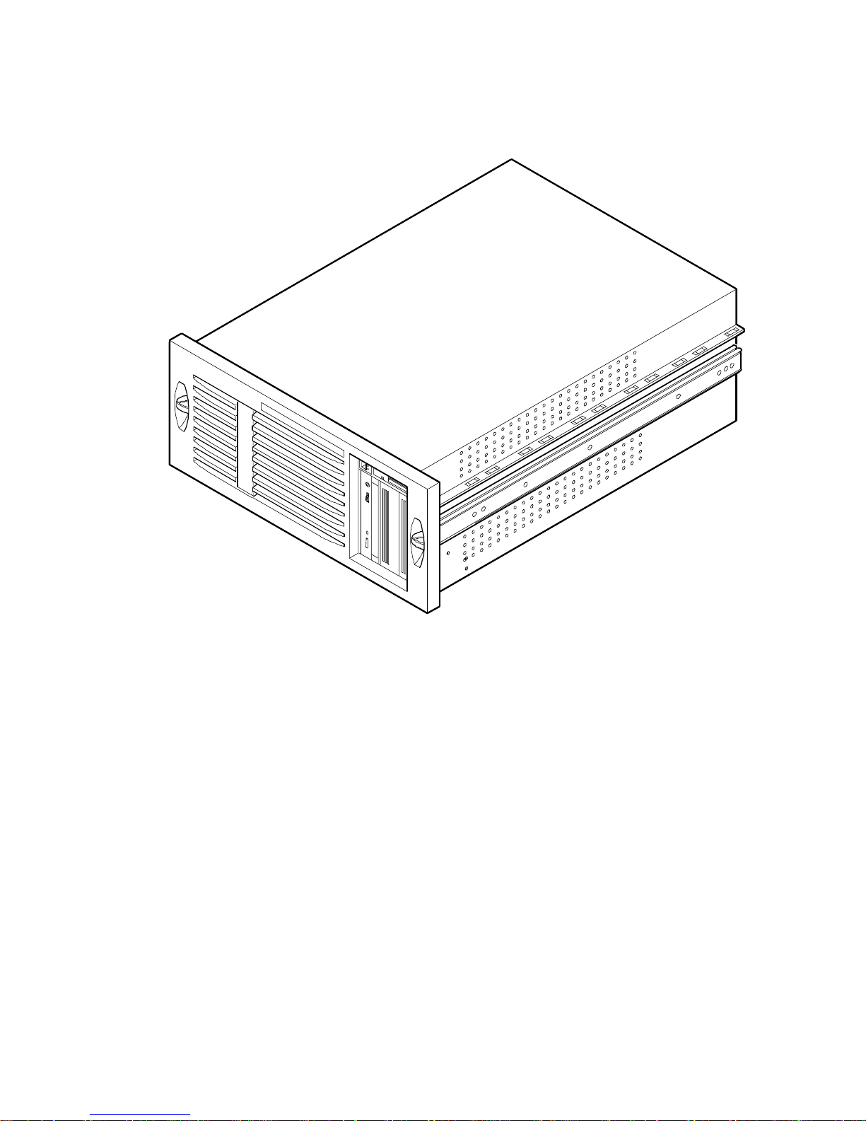
Typi c a l DIGITAL S e rv e r 3100R /3200R.................................................................... viii
2-1. SCU Main Menu Options......................................................................................... 2-6
4-1. DIGIT AL Se rv e r C o mponent Information................................................................. 4-7
5-1. Server Front and Top View...................................................................................... 5-3
5-2. Se rv e r T o p V iew (Penti u m P r o P ro c e s so r).............................................................. 5-5
5-3. Se rv e r T o p V iew (Penti u m II P r o ce s s o r).................................................................. 5-7
5-4. Re mo v i n g th e Top C o v e r......................................................................................... 5-11
5-5. Insta lli n g th e T o p Cover........................................................................................... 5-13
5-6. Se rv e r F ro n t V iew.................................................................................................... 5-15
5-7. Se rv e r T o p V iew (F ro n t Bezel Remo v e d )................................................................ 5-17
5-8. Se rv e r R e a r V i e w..................................................................................................... 5-19
5-9. Main Logic Board Connectors.................................................................................. 5-21
5-10. Main Logic Board Components................................................................................ 5-23
5-11. Pentium Pro Processor Module Components and Connectors ............................... 5-25
5-12. Pentium II Processor Module Components ............................................................. 5-27
5-13. Ethernet Daughter Card Components and Connectors........................................... 5-28
5-14. Main Logic Board Switch and Jumper Locations..................................................... 5-31
5-15. Pentium Pro Processor Module Switch Locations ................................................... 5-33
5-16. Pentium II Processor Module Switch Settings ......................................................... 5-36
5-17. Processor Module SIMM Bank Locations................................................................ 5-39
5-18. D IMM Socke t L o c a ti o n s........................................................................................... 5-43
5-19. Removing and Replacing the Power Supply............................................................ 5-47
5-20. Removing and Replacing the Diskette Drive............................................................ 5-49
5-21. Removing and Replacing the CD-ROM Drive.......................................................... 5-51
5-22. Removing and Replacing the Drive Bay Cooling Fan .............................................. 5-53
5-23. Removing and Replacing the Speaker..................................................................... 5-55
5-24. Removing and Replacing the Main Logic Board...................................................... 5-58
5-25. R e mo v i n g th e Front B e z e l ........................................................................................ 5-60
5-26. Removing and Replacing the Server Battery/RTC................................................... 5-61
5-27. Removing and Replacing the Storage Backplane.................................................... 5-63
5-28. Removing and Replacing the OCP assembly.......................................................... 5-65
5-29. Removing and Replacing the Fault Status LED Assembly ...................................... 5-67
6-1. Removing the Processor Module............................................................................. 6-6
6-2. Removing the Retaining Clip.................................................................................... 6-7
6-3. Re mo v i n g th e Proce ss o r/Heat S i n k A s s e mb l y ......................................................... 6-8
6-4. Insta lli n g th e N e w Proc e s s o r.................................................................................... 6-9

Contents
vi
6-5. Installing the Retaining Clip...................................................................................... 6-10
6-6. Insta lli n g a V RM....................................................................................................... 6-11
6-7. Installing the Processor Module............................................................................... 6-12
6-8. Removing the Processor Module............................................................................. 6-16
6-9. Removing the Terminator Module............................................................................ 6-17
6-10. Installing the Second Processor............................................................................... 6-18
6-11. In sta lli n g a V RM....................................................................................................... 6-19
6-12. Installing the Processor Module............................................................................... 6-20

vii
DIGIT AL Server 3100R/3200R
Preface
P
This
Service Maintenance Manual
is a troubleshooting guide that can be used for
reference when servicing DIGITAL Serv e rs.
DIGITAL re s e rve s th e r ight to make changes to this
Service Maintenance Manual
without notice. Accordingly, the illustrations and procedures in this document might
not apply to all DIGITAL Servers to b e s e rv i ce d s i n ce m a n y o f th e diagnostic tests
are designed to test more than one product.
CAUTION:
DIGITAL recommends that only
A+/DIGITAL Server certified engineers attempt to repair
this equipment. All troubleshoot ing and r epair
procedures are det ailed to support subass em bly /module
level exchange. Bec aus e of the complexit y of the
individual boards and subassem blies , no one should
attempt to make repairs at the component level or mak e
modifications to any printed circ uit board. Improper
repairs can create a safety haz ar d. Any indications of
component replacem ent or circuit boar d m odifications
might void any warr anty or exchange allowances.
Preface
viii
DEC01429
Typical D IGITA L S erver 3100R/3200R

1-1
DIGIT AL Server 3100R/3200R
1
Product Description
1
System Introduction
The DIGITA L Se r ve r 3100R/3200R is a high-performance, highly-scaleable
departmental server featuring the latest in modular processor and storage
technology.
The DIGITA L Se r ve r p r o v ides support for the following features:
Reliabilit y /A v a ila bilit y
Rackmountable
The DIGITA L Se r ve r c a n b e m ounted into any industry-
standard 19-inch rack. Note that the rack, monitor,
keyboard, and mouse must be purchased separately.
Pentium Pro or Pentium
II Processor Module
Pentium Pro processor module. Each Pentium Pro
processor requires 36-bit SIMMs with 60 ns access time.
It will operate with either EDO or Fast Page memory.
Or
Each Pentium II processor operates using 168-pin, 72-bit
DIMMs with 60 ns access time and ECC protected EDO
memory.
Error Correction Code
(ECC) Memory
Recovery from most cache and memory errors.
continued

Product Description
1-2
Internal Sensors
Monitors internal server temperatures, fan operation, and
voltages for the main logic board and processor module.
Clusters
Supports DIGITAL Clusters for Windows NT and Microsoft
Cluster Server (part of Microsoft Windows NT Server,
Enterprise Edition) for database and file services failover.
Server Ex pansion
Flexible Memory
Architecture
ECC memory supported. Server memory can be
upgraded from 32 MB to a maximum of 1 GB using SIMM
memory on a Pentium Pro processor module. For
Pentium II processor modules, server memory can be
upgraded from 32 MB to a maximum of 512 MB using
DIMM memory.
Four EISA Expansion
Slots, Two PCI
Expansion Slots, and
One Shared PCI/EISA
Expansion Slot
Accommodates industry-standard expansion boards such
as network, Small Computer System Interface (SCSI),
Redundant Array of Independent Disks (RAID), and
modems.
Integrated PCI and
SVGA Video Controller
Supports management and configuration applications
locally (on main logic board) without use of an expansion
slot.
Wide Ultra SCSI
Controller
Supports narrow and wide Ultra SCSI internal devices.
continued

Product Description
1-3
DIGITAL S erver 3100R/3200R
Capacity for Seven
Internal Storage Devices
Accommodates four 3½-inch half-height SCA-2 disk
drives, one CD-ROM (standard), a 3½-inch diskette drive
(standard), and two narrow (50-pin) half-height, 5¼-inch
devices; or one full-height, 5¼-inch device such as a CD-
ROM or tape drive.
External I/O Ports
Two serial ports and one Enhanced Parallel Port (EPP) to
support external options such as a printer, modem, or local
terminal.
SCA-2 Storage
Backplane
Supports high-performance SCSI SCA-2 disk drives.
Disk Hot Swap Capability
Allows replacement of SCSI SCA-2 disk drives while the
server is operating.
External Network
Ports/Integrated Network
Controller
A DIGITAL E th e rn e t c o n troller on the main logic board.
An Ethernet daughter card provides: one 10/100Base-T
(10/100 Mb/s) port, one 10Base-2 (10 Mb/s) port, and one
10Base-5 (AUI) port.

Product Description
1-4
Server Management and Security
Server Diagnostics
Allows local and remote diagnosis of server problems.
Hardware Configuration
Allows local and remote server configuration.
Unique Asset
Management
Unique server identifier in non-volatile memory provides
easy asset management.
BIOS and Firmware
Upgrade Utility
Upgrades the BIOS and firmware versions.
SCA-2 Disk Drive
Indicator LEDs
Provides immediate status information on SCA-2 disk
drive activity or failure.
Server Fault Status
LEDs
Provides immediate status information on server fan,
temperature, voltage, and memory failure.

Product Description
1-5
DIGITAL S erver 3100R/3200R
Server Configurations
The following rules apply when
Product Fa m ily Names
and
Product Mode l Names
are assigned to DIGITAL Server p r oducts. These rules apply to all products
developed in the NT Server Business Unit (NTSBU).
Server Naming Guidelines
•
All products in a family carry the same name on the nameplate. (i.e. all
products in the Entry space will carry the name DIGITAL SERVER 1000)
Family Name Segment
DIGITAL SER V ER 500
SUB ENTRY
DIGITAL SER V ER 1000
ENTRY
DIGITAL SER V ER 3000
DEPARTMENT
DIGITAL SER V ER 5000
APPLICATION
DIGITAL SER V ER 7000
ENTERPRISE
DIGITAL SER V ER 9000
SUPER ENTERPRISE
•
Products in a rackmount chassis will have an R after the Family Name
(DIGITAL S e rve r 3000R).
•
Product models within a family will be differentiated by the Product Model
Name. The Product Model Name will appear on a label on the rear of the
product. Specific configurations within a model will carry the same Product
Model Name and will be differentiated by the FR part number.

Product Description
1-6
Product Model Numbering Convention
The following example describes the product model numbering convention:
DIGITAL SER V ER 1234 5678A R
1 = PRODUCT FAMILY NAME (first character of family number)
2 = MAJOR PROCESSOR TECHNOLOGY DIFFERENTIA TOR WITH IN TH E
FAMILY
This number will be assigned to each new platform based on the following matrix.
Open numbers will be assigned as new processor technology is introduced. THIS
FIELD IS NOT USED FOR SUB ENTRY PRODUCTS.
100 = Pentium Pro
200 = Pentium II – Slot 1
300 = EV5
400 = Pentium II – Slot 2
500 = EV6
600 = OPEN
700 = OPEN
800 = OPEN
900 = OPEN
3,4 = USED TO D IFFERE N TIATE MODE LS BASED UP ON DIFFER EN T
PROCESSORS WITHIN A PROCESSOR TECHNOLOGY (I.E. CLOCK SPEED,
CACHE SIZE) START AT 00 FOR FIRST MODEL AND INCREMENT BY 05 FOR
EACH A D D ITION AL M OD EL .

Product Description
1-7
DIGITAL S erver 3100R/3200R
5 = CPU TYPE
BLANK = PENTIUM
1= PENTIUM PRO
2 = PENTIU M II/SL OT 1
3 = PENTIU M II/SL OT 2
4 = Open/Available for future processors
5 = Open/Available for future processors
6 = ALPHA EV56
7 = ALPHA PCA57
8 = ALPHA EV6
9 = ALPHA EV67
6, 7, 8,9 = CPU CLOCK SPEED IN MHZ

Product Description
1-8
Related Material
The following related material is available:
Document or Software Title Order Number Description
Service Quick Reference ER-R2CWW-SR (English only) Provides troubleshooting
information that can be used when
servicing DIGITAL servers. This
manual is a condensed version of
the Service Maintenance Manual
and is provided in a pocket-size
format (4 x 8-inches).
Installation Guide ER-R2CWW-IM (Multilanguage)*
ER-R2CWW-IJ (Japanese)
Provides information on connecting
hardware cables and booting the
server. This guide also explains
how to use DIGITAL
ServerWORKS Quick Launch to
install an operating system, create
driver and utility diskettes, and view
on-line help and support
documentation.
System Reference ER-R2CWW-UA (English)
ER-R2CWW-UJ (Japanese)
Provides information on using the
server’s configuration utilities,
installing peripherals and options,
security, and troubleshooting. The
System Reference is available on
the Quick Launch CD-ROM in
English, Spanish, German, Italian,
and French.
Quick Reference labels 36-49411-01 (inside top cover)
36-49412-01 (inside top cover)
36-49413-01 (front bezel)
Provides an overview of major
server components, configuration
guidelines, SCSI cabling, and fault
status information. These labels are
located on the inside of the server’s
top cover and on the front bezel.
Warranty and Service
Information
ER-PCWAR-CM
(Multilanguage)*
Provides warranty information and
a listing of phone numbers for
technical support.
* Multilanguage includes: English, French, Italian, German, and Spanish
continued

Product Description
1-9
DIGITAL S erver 3100R/3200R
Document or Software Title Order Number Description
DIGITAL ServerWORKS software QB-4WY9A-SA
(Multilanguage)*
Contains ServerWORKS Quick
Launch and ServerWORKS
Manager software and
documentation.
Quick Launch consists of a bootable
CD-ROM disk and Getting Started
guide. This program steps the user
through the initial server setup and
operating system installation.
ServerWORKS Manager consists of
two CD-ROMs and an Overview and
Installation Guide and supporting
documentation.
Product README and Revision
History Information - Quick
Launch CD-ROM
Refer to the Quick Launch
CD-ROM in the DIGITAL
ServerWORKS software kit.
Provides additional product
information and product change
history.
Option documentation - Quick
Launch CD-ROM
Refer to the Quick Launch
CD-ROM in the DIGITAL
ServerWORKS software kit.
Provides postscript files that can be
viewed and printed using Adobe
Acrobat Reader software. These
files are provided in PDF format on
the Quick Launch CD-ROM.
Diagnostic Software - Quick
Launch CD-ROM
Refer to the Quick Launch
CD-ROM in the DIGITAL
ServerWORKS software kit.
Contains an advanced set of
diagnostic utilities for identifying and
correcting problems on the server.
The diagnostic software can be used
to verify proper hardware installation
and isolate intermittent problems that
are not detected by the Power On
Self Test (POST). Refer to chapter
2 for information on using the
diagnostic utilities.
PC Product Support Information
Kit
QA-5RJAA-G8 (English only) Provides all the latest user
documentation for all NTSBU mobile,
desktop, and server products.
* Multilanguage includes: English, French, Italian, German, and Spanish
Refer to chapter 2 for procedures for creating diskettes and viewing
documentation from the Quick Launch CD-ROM.

Product Description
1-10
Latest Product Information and Updates
Listed below is the current product information and update source locations.
Server Product Information
Family Name Model Name Part Number Description
DIGITAL Server
3000R
DIGITAL Server
3105 1200R
FR-R2C5W-AA 6266/512 (PII) - MODEL 1
DIGITAL Server
3000R
DIGITAL Server
3105 1200R
FR-R2C5W -AX 6266/512 (PII) - KERNAL
DIGITAL Server
3000R
DIGITAL Server
3200 2266R
FR-R2C6W -AA 6300/512 (PII) - MODEL 1
DIGITAL Server
3000R
DIGITAL Server
3200 2266R
FR-R2C6W -AX 6300/512 (PII) - KERNAL
Powergrade Chip
Upgrade
DIGITAL Server
3000 Powergrade
Upgrade Kit
FR-PCB4U-AD 6266/256 (PII) Powergrade Chip
Upgrade
Powergrade Board
Upgrade
DIGITAL Server
3000 Powergrade
Upgrade Kit
FR-PCB4U-AE 6266/512 (PII) Powergrade Board
Upgrade
Powergrade Chip
Upgrade
DIGITAL Server
3000 Powergrade
Upgrade Kit
FR-PCB4U-AF 6300/512 (PII) Powergrade Chip
Upgrade
Powergrade Board
Upgrade
DIGITAL Server
3000 Powergrade
Upgrade Kit
FR-PCJ2U-AB 6300/512 (PII) Powergrade Board
Upgrade

Product Description
1-11
DIGITAL S erver 3100R/3200R
Pentium Pro vs Pentium II Comparison Chart
Item Pentiu m P ro Pe ntium II
Clock Speed 200 MHz 266 MHz or 300 MHz
System Bus Speed 66 MHz 66 MHz
Form Factor Socket 8 (PGA) Single Edge Contact (SEC)
cartridge
Number o f CPUs 2 2
L1 Cache
(instruction/Data)
16 KB 32 KB
L2 Cache Internal External (in SEC cartridge)
L2 Bus Speed Full Speed Half Speed
L2 ECC Yes 512 KB only
L2 Cache Size 256/512 KB 512 KB
MMX Instructions No Yes
Memory All ECC All ECC
Type SIMM (EDO and Fast
Page)
DIMM (EDO)
Maximum 1 GB 512 MB
Updates
Current server utilities and technical support information is available on the Quick
Launch CD-ROM disc and the Internet.
For product information, use the address:
http://www.windows.digital.com
For technical support, use the address:
http://www.windows.digital.com/support/support.asp
For access directly to the software library for BIOS and driver updates, use the
address:
http://www.windows.digital.com/~ftp/00-index.stm

2-1
DIGIT AL Server 3100R/3200R
2
Server Software and Utilities
2
Introduction
This chapter describes the utilities supplied with the server. Server utilities include:
•
ServerWORKS Quick Launch This software is used to install a network
operating system onto the server. The CD-ROM also contains various
drivers and on-line documentation.
•
System Configuration Utility (SCU) This utility is available to configure the
server when relocating, adding, or removing EISA/ISA/PCI expansion
boards and when changing the server’s factory-defined settings. The SCU is
available on the Quick Launch CD-ROM.
•
RAID Configuration Utility This utility is available for RAID-ready servers
only. This utility is available to configure the RAID array. The RAID
configuration utility is available on the Quick Launch CD-ROM.
•
BIOS Upgrade Utility This utility is available to update or restore the
server’s BIOS. The BIOS Upgrade Utility is available on the Internet.
•
SCSI
Select
Utility This utility allows you to configure and view settings of
the onboard SCSI controller and SCSI devices. The SCSI
Select
Utility is
available each time you boot the server.
•
Diagnostics This utility is used to verify server operation. The diagnostics
utility is available on the Quick Launch CD-ROM.

Server Software and Utilities
2-2
ServerWORKS Quick Launch
ServerWORKS Quick Launch is used to install the server’s Network Operating
System (NOS). In addition to providing quick and seamless NOS installation, Quick
Launch also provides drivers, documentation, and the ability to make diskettes of
utilities such as diagnostics. For more information, refer to the
ServerWORKS Quick
Launch Getting Started
guide.
Creating Diskettes and Viewing On-line Documentation
Use the following procedure to create diskettes using the Quick Launch CD-ROM
and to view on-line product documentation.
1. Power on the server and boot the ServerWORKS Quick Launch CD-ROM.
2. Select the “User Documentation” button to view on-line product
documentation.
3. From the Quick Launch Main Screen, select the “Installations & Utilities”
button and then the Utility tab to create driver and utility diskettes.
4. Insert a DOS-formatted diskette into drive A, and choose the utility or driver
you wish to copy and select Continue.
5. Repeat this procedure for all the utilities and drivers you wish to copy.

Server Software and Utilities
2-3
DIGITAL S erver 3100R/3200R
System Configuration Utility (SCU)
The server was pre-configured at the factory using the System Configuration Utility
(SCU). This means that the server’s hardware (processor modules, memory, cache,
mass storage devices, expansion boards, etc.) has been identified and configured for
optimum performance. If configuration changes are required, DIGITAL recommends
that the SCU be used along with the information provided in this section.
Refer to “Starting the SCU” described later in this section.
Refer to Chapter 3, “SCU Features,” for more details about the SCU.
Refer to the ServerWORKS Quick Launch Getting Started guide and the
README.TXT file, which is located on the Quick Launch CD-ROM, for additional
information.
When to Run the SCU
Always run the SCU each time you add, remove, or relocate ISA, PCI and/or EISA
expansion boards to reconfigure server resources (IRQs). Always run the SCU if the
main logic board changed, or after adding a processor module.
If the main logic board changes or a processor module is added, run the SCU (select
the option “Configure Computer”) to update the serial numbers of the components.
For more information on how to change the serial numbers, refer to Chapter 4,
“Obtaining Information About The Server.”
Typically, the server displays a message such as
Run SCU Utility.....Press
F1 to Continue
. Select how to access and run the SCU by following the
instructions displayed on the SCU screens.

Server Software and Utilities
2-4
Configuring Expansion Boards
Each time you add, remove, or relocate any EISA/ISA/PCI expansion board, you
need to run the SCU to identify their operating characteristics, server resource
requirements, and slot locations. Based on this information, the SCU will then
automatically assign the proper server resources to EISA expansion boards, enable
PCI boards, and inform you as to what jumper or switch settings need to be manually
set on ISA expansion boards to avoid resource conflicts.
The SCU identifies an expansion board’s operating characteristics and resource
requirements through Configuration (.CFG) files. These files contain main logic
board, EISA, PCI, and ISA expansion board vital characteristics and the server
resources they require for proper operation. Before configuring the server, copy the
CFG files (and overlays if applicable) supplied with the additional EISA expansion
boards to either the SCU directory on the hard disk drive or to the SCU diskette.
As an added feature, the SCU creates and stores all setup changes in a System
Configuration (.SCI) file. This file is automatically generated when the SCU runs.
Afterwards, this SCI file can be used on any DIGITAL Server th a t i s identically
configured and can serve as a backup to the EISA configuration stored in NVRAM
memory.
Starting the SCU
The SCU is located on the ServerWORKS Quick Launch CD-ROM disc. The SCU
options are shown in Figure 2-1. If this is the first time using the SCU, it is
recommended that you select “Learn About Configuring your Computer” for detailed
information on using the SCU. If this is a subsequent session, refer to the
appropriate sections in this chapter to change the server’s configuration.

Server Software and Utilities
2-5
DIGITAL S erver 3100R/3200R
Start the SCU in one of three ways:
1. During the Quick Launch boot process, if a DOS partition was created, the
SCU was copied to the partition on the hard disk drive. This allows you to
run the SCU anytime from the DOS partition.
At the MS-DOS prompt change to the SCU directory and type:
SCU.BAT
2. Creating a bootable SCU diskette by using the Quick Launch CD-ROM and
selecting the Installations & Utilities button and then the Utilities page. On
the Utilities page, select the appropriate BIOS level for the server that the
SCU is being created for (if this is being done on the server, the default
BIOS that is highlighted is the BIOS of that server).
Afterwards, run the SCU anytime using the SCU diskette.
3. The SCU can also be run by inserting the Quick Launch CD-ROM disc,
rebooting the server, and pressing and holding the right [ALT] key during the
boot process to display the SCU.
NOTE:
If EI S A ( in s om e c as es , PCI) cards hav e been
added to the serv er , the SCU will be invoked aut om atically
when booted from the Quick Launch CD-ROM disc. The
.SCI f ile is not saved when using this m ethod to run the
SCU.
Server Software and Utilities
2-6
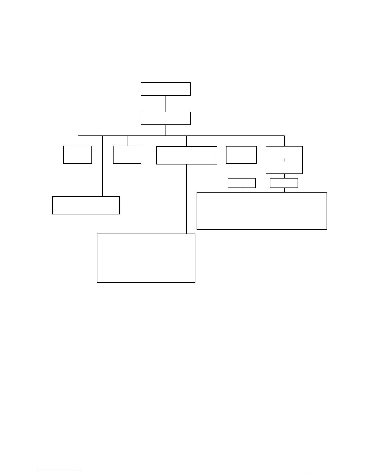
Welcome Screen
Main Menu
Set Date Set Time
Maintain System
Configuration Diskette
Configure
Computer
Configure
Computer
With System
Default
Learn About Configuring
Your Computer
See Note
See Note
Step 1: Important EISA Configuration Information
Step 2: Add or Remove Boards
Step 3: View or Edit Details
Step 4: Examine Switches or Print Report
Step 5: Save and Exit
Create a Backup SCI File
Load a Backup SCI File
Copy/Update CFG Files
Copy/Update SCI Files
Delete CFG Files
Delete SCI Files
Return to the Main Menu
DEC0045
6
Note:
If new boards are found, the following
message displays: The following changes have
automatically been made: [ Action: ]
Figure 2- 1 . SC U Ma in M e nu Options

Server Software and Utilities
2-7
DIGITAL S erver 3100R/3200R
Using the SCU
To use the SCU:
1. Turn on the server and allow the Power-On Self Test (POST) to complete.
If POST detects an error refer to Chapter 4, “Troubleshooting,” and take the
appropriate steps to correct the problem. After the problem has been
resolved, restart the server.
2. Start the SCU using one of the three methods described previously.
3. Press [Enter] to display the SCU introductory screen.
NOTE:
The SCU contains help pop-up screens for any
selected menu it em . Press [F1] at anytim e to display a help
screen. Press [Esc] to remove a help screen.
4. If no configuration errors appear, the Welcome screen displays.
Press [Enter] to display the Main menu.
If a configuration error appears, the Welcome screen displays information
about the error and then prompts you to reconfigure the server.
5. Step through the menu items to familiarize yourself with the SCU.
 Loading...