

Digital Equipment 300 Series AXP Reference Manual

DEC3000Model300SeriesAXP
HardwareReferenceGuide
Order Number: EK–PELCN–OG. C01
Digital Equipment Corporation, Maynard, MA

Second Printing, January 1994
The information in this document is subject to change without notice and
should not be construed as a commitment by Digital Equipment Corporation.
Digital Equipment Corporation assumes no responsibility for any errors that
may appear in this document.
© Digital Equipment Corporation, 1994.
All Rights Reserved.
Printed in U.S.A.
The postpaid Reader’s Comments form at the end of this document requests
your critical evaluation to assist in preparing future documentation.
The following are trademarks of Digital Equipment Corporation: AXP,
Alpha AXP, DEC, DEC Open3D, DEC PHIGS, DECchip, DECnet, DECwindows,
Digital, OpenVMS, RX, RZ, ThinWire, TURBOchannel, VAX DOCUMENT and
the DIGITAL logo.
Open Software Foundation is a trademark of, and Motif, OSF, OSF/1 and
OSF/Motif are registered trademarks of the Open Software Foundation, Inc.
CD is a trademark of Data General Corporation; ISDN is a registered
trademark of Fujitsu Network Switching of America; MIPS is a trademark
of MIPS Computer Systems, Inc.; PostScript is a registered trademark of Adobe
Systems Incorporated.
All other trademarks and registered trademarks are the property of their
respective holders.
FCC NOTICE: This equipment has been tested and found to comply with
the limits for a Class A digital device, pursuant to Part 15 of the FCC Rules.
These limits are designed to provide reasonable protection against harmful
interference when the equipment is operated in a commercial environment.
This equipment generates, uses, and can radiate radio frequency energy and, if
not installed and used in accordance with the instruction manual, may cause
harmful interference to radio communications. Operation of this equipment in
a residential area is likely to cause harmful interference, in which case users
will be required to correct the interference at their own expense.
S2437
This document was prepared using VAX DOCUMENT Version 2.1.

Contents
Preface ..................................................... xi
1 Introduction to Your System
Chapter Overview . ................................... 1–1
Product Description ................................... 1–2
Operating Systems . ................................... 1–7
Graphics Capabilities .................................. 1–9
Integrated Services Digital Network (ISDN) ................ 1–11
Audio Capabilities . ................................... 1–12
System Personalization Capabilities . . . ................... 1–13
Firmware Update Utility ............................... 1–14
2 Adding, Removing, and Replacing Internal Options
Chapter Overview . ................................... 2–1
Recording Information Before Making Changes .............. 2–3
Understanding SCSI IDs ............................... 2–12
Preparing Your System ................................ 2–13
Identifying and Locating Options ......................... 2–21
Removing and Installing a Removable-Media Drive . .......... 2–22
Removing and Installing a Fixed Disk Drive ................ 2–27
Removing and Installing a Memory Module ................. 2–33
Removing and Installing a TURBOchannel Option (For Models
300/300X/300LX Systems) . . . ........................... 2–38
Removing and Installing the CPU Module .................. 2–44
Removing and Installing the Power Supply ................. 2–46
Removing and Installing the System Module ................ 2–50
Restoring the System .................................. 2–55
iii

3 Connecting External Options
Chapter Overview . ................................... 3–1
Headset . ........................................... 3–2
Tablet. . . ........................................... 3–2
Printers . ........................................... 3–3
Modems . ........................................... 3–3
Expansion Boxes . . ................................... 3–4
Compact Disc Drive ................................... 3–5
External Device Connections ........................... 3–6
4 Using Console Commands
Chapter Overview . ................................... 4–1
Before You Begin . . ................................... 4–3
Diagnostics ......................................... 4–6
BOOT . . . ........................................... 4–8
CONTINUE ......................................... 4–15
DEPOSIT ........................................... 4–16
EXAMINE .......................................... 4–20
HALT.............................................. 4–24
HELP . . . ........................................... 4–25
INITIALIZE ......................................... 4–29
LOGIN . . ........................................... 4–30
REPEAT. ........................................... 4–31
SET ............................................... 4–32
SHOW . . ........................................... 4–45
START............................................. 4–58
TEST . . . ........................................... 4–59
5 Using the Password Security Feature
Chapter Overview . ................................... 5–1
Secure Console Commands . . ........................... 5–2
Invoking the Password Security Feature ................... 5–3
Changing, Erasing, and Disabling the Password . . . .......... 5–7
iv

6 Using an Alternate Console Device
Chapter Overview . ................................... 6–1
Setting the Alternate Console Feature . . ................... 6–2
7 Troubleshooting by Visual Inspection
Chapter Overview . ................................... 7–1
Using the Troubleshooting Tables ........................ 7–2
Cleaning Your System ................................. 7–10
8 Advanced Diagnostics
Chapter Overview . ................................... 8–1
Preliminary Power-up Test Displays . . . ................... 8–2
Messages from Other Tests . . ........................... 8–11
Problem Worksheet ................................... 8–12
A Hardware Specifications
Appendix Overview ................................... A–1
System Specifications .................................. A–2
B Internal Options: Specifications and SCSI ID Settings
Appendix Overview ................................... B–1
RX26 Drive Specifications . . . ........................... B–2
RX26 Diskette Specifications . ........................... B–3
RZ25 Fixed Disk Specifications .......................... B–6
RZ25L Fixed Disk Specifications ......................... B–12
RZ26 Fixed Disk Specifications .......................... B–15
RZ26L Fixed Disk Specifications ......................... B–18
RZ28 Fixed Disk Specifications .......................... B–21
C Port Pinouts
Appendix Overview ................................... C–1
External SCSI Port ................................... C–2
10BASE-T Port . . . ................................... C–4
ISDN Port .......................................... C–5
Audio Port .......................................... C–6
Keyboard/Mouse or Tablet Port .......................... C–7
RS-232 Synchronous/Asynchronous Communications Port ...... C–8
v

D Associated Documents
E Help in Debugging Programs
Appendix Overview ................................... E–1
Examining the Impure Area . ........................... E–2
Examining the Machine Check Logout Area ................ E–3
F Supplementary Information for PTT Network Users
Appendix Overview ................................... F–1
Glossary
Index
Figures
1 Guide to DEC 3000 Model 300 Series AXP
Documentation . ................................... xv
1–1 System Components ................................ 1–2
1–2 Firmware Update Jumper ........................... 1–15
2–1 The show device Display . ........................... 2–4
2–2 The show config Display . . ........................... 2–6
2–3 Configuration Display with Error at Startup . . . .......... 2–9
2–4 The show mem Display . . ........................... 2–11
2–5 Turning Off the System Unit ......................... 2–16
2–6 Removing the System Cover ......................... 2–18
2–7 Attaching the Antistatic Wrist Strap ................... 2–19
2–8 Power Cable and Connectors ......................... 2–19
2–9 SCSI Cable and Connectors .......................... 2–20
2–10 Device Positions ................................... 2–21
2–11 Removing a Removable-Media Drive ................... 2–23
2–12 Installing the Shield and Filler Panel .................. 2–24
2–13 Removing the Shield and Filler Panel .................. 2–25
2–14 Cabling the RX26 Drive . . ........................... 2–26
2–15 Removing a Disk Drive . . ........................... 2–28
2–16 Removing the Mounting Bracket from a Disk Drive ....... 2–29
vi

2–17 Cabling a Drive in Position 1 ......................... 2–30
2–18 Cabling a Drive in Position 2 ......................... 2–31
2–19 160 MB Memory Configuration ....................... 2–34
2–20 8-Megabyte SIMM ................................. 2–35
2–21 32-Megabyte Simm ................................ 2–35
2–22 Removing and Installing a Memory Module .............. 2–36
2–23 Removing and Installing a TURBOchannel Option ........ 2–41
2–24 Removing the TURBOchannel Filler Plate............... 2–42
2–25 Removing the CPU Module .......................... 2–45
2–26 The Power Supply Cable . ........................... 2–47
2–27 Removing the Power Supply ......................... 2–48
2–28 Reinstalling the Metal Shield......................... 2–49
2–29 Removing the Ethernet ROM ........................ 2–51
2–30 Removing the System Module ........................ 2–53
2–31 Replacing the System Cover .......................... 2–56
2–32 Reconnecting the System . ........................... 2–58
2–33 System Display After Restoring Your System . . .......... 2–59
3–1 External Connections to the System Unit ............... 3–6
5–1 The Secure System Jumper .......................... 5–5
6–1 Connecting the Alternate Console to the System .......... 6–3
6–2 Alternate Console Jumper ........................... 6–5
8–1 Position of Diagnostic Display Lights................... 8–3
B–1 RX26 Switch Settings . . . ........................... B–5
B–2 RZ25 Jumper Settings . . . ........................... B–9
B–3 RZ25L Jumper Settings . . ........................... B–14
B–4 RZ26 Jumper Settings . . . ........................... B–17
B–5 RZ26L Jumper Settings . . ........................... B–20
B–6 RZ28 Jumper Settings . . . ........................... B–23
C–1 Communications Ports . . . ........................... C–1
F–1 Ports to Which Warning Label Applies ................. F–5
vii

Tables
1 Telephone Numbers of Digital Support Centers . .......... xiv
1–1 System Features .................................. 1–3
2–1 Elements of the show device Display ................... 2–5
2–2 Elements of the show config Display ................... 2–7
2–3 Elements of the show mem Display . ................... 2–11
2–4 TURBOchannel Options . . ........................... 2–39
4–1 Supported Keys and Control Characters ................ 4–4
4–2 Parameters/Qualifiers for the
4–3 Device Names . ................................... 4–11
4–4 Naming Convention Common to Both Operating Systems
................................................ 4–12
4–5 Alternate Naming Convention for DEC OSF/1 System . . . . . 4–12
4–6 set[env] Command Environment Variables and Values . . . . . 4–33
4–7 boot_osflags Command Values ........................ 4–39
4–8 set diag_section Command Values . . ................... 4–40
4–9 Selecting a Keyboard Language ....................... 4–42
4–10 Environment Variables and Values for the
................................................ 4–46
4–11 Test Devices . . . ................................... 4–60
4–12 Erase Disk Utility Prompts .......................... 4–62
4–13 Diskette Formatter Utility Prompts . ................... 4–63
4–14 Verify Utility Prompts . . . ........................... 4–64
4–15 ASIC Diagnostic Subtests ........................... 4–66
4–16 FEROM Diagnostic Subtests ......................... 4–67
4–17 Memory Diagnostic Subtests ......................... 4–68
4–18 NVR Diagnostic Subtests . ........................... 4–69
4–19 SCC Diagnostic Subtests . ........................... 4–70
4–20 NI Diagnostic Subtests. . . ........................... 4–71
4–21 TC Diagnostic Subtests . . ........................... 4–74
4–22 SCSI Diagnostic Subtests. ........................... 4–75
4–23 ISDN Diagnostic Subtests ........................... 4–77
4–24 CXT Diagnostic Subtests . ........................... 4–78
5–1 Console Command Access ........................... 5–2
5–2 Steps to Making the System Secure . ................... 5–3
5–3 Entering a Password ............................... 5–3
5–4 Entering a Login Command .......................... 5–6
boot
Command . . .......... 4–8
show
Command
viii

5–5 Changing a Password............................... 5–7
6–1 Using the Alternate Console ......................... 6–2
6–2 Alternate Console/Printer Port Parameters .............. 6–4
7–1 Preliminary Troubleshooting of System Problems ......... 7–3
7–2 Troubleshooting Monitor Problems . . ................... 7–5
7–3 Troubleshooting Mouse/Tablet Problems ................ 7–6
7–4 Troubleshooting Keyboard Problems ................... 7–7
7–5 Troubleshooting SCSI Device Problems ................. 7–7
7–6 Troubleshooting Network Problems . ................... 7–8
7–7 Troubleshooting Audio Problems . . . ................... 7–9
8–1 Console LED Codes ................................ 8–4
8–2 FRU Codes ....................................... 8–6
8–3 Console-Level Problems . . ........................... 8–10
A–1 System Unit Dimensions - Desktop . ................... A–2
A–2 System Power Specifications ......................... A–2
A–3 System Specifications . . . ........................... A–3
A–4 System Environmental Specifications .................. A–4
A–5 Acoustics—Declared Values per ISO 9296 and ISO 7779 . . . . A–5
B–1 J5 Jumper Settings ................................ B–10
B–2 J6 Jumper Settings ................................ B–10
B–3 J7 Jumper Settings ................................ B–11
B–4 RZ25L Hardware Specifications ....................... B–12
C–1 External SCSI Port Pin-outs ......................... C–2
C–2 10BASE-T Port Pin-outs . ........................... C–4
C–3 ISDN Port Pin-outs ................................ C–5
C–4 Audio Port Pin-outs ................................ C–6
C–5 Keyboard/Mouse or Tablet Port Pin-outs ................ C–7
C–6 Synch/Asynch Communications Port Pin-outs . . .......... C–8
D–1 DEC 3000 Model 300 Series AXP System Printed
Documents ....................................... D–1
D–2 End User Documentation, QA–MT4AB–GZ .............. D–4
D–3 General OpenVMS AXP Operating System Documents . . . . . D–5
D–4 Miscellaneous Documents ........................... D–5
F–1 Service Specifications for the System Module . . .......... F–2
F–2 Module Power . ................................... F–3
F–3 Clearance and Creepage Distances . ................... F–4
F–4 Cables Supported by the Approved Module .............. F–7
ix


Preface
About This
Guide
Two Methods of
Adding Options
This guide describes how to:
• Remove and replace internal options
• Connect external options
• Use console commands to run tests and utilities, and to set
and show the value of parameters
• Set the password security feature
• Connect and use an alternate console
• Identify and solve problems
This guide also provides system and option specifications, port
pinouts, a list of associated documents, help in debugging
programs, and information for PTT network users.
You can add internal options by:
• Adding the options yourself.
• Having a Digital service representative add them.
You can add external options to your system, by connecting them
to the SCSI port, the ISDN port, the Audio port, and the RS232
asynchronous/synchronous communications port.
If you choose to add internal options yourself, note that additions
typically take about 15 minutes for each option. If you choose
to add external options, note that additions typically take about
5 minutes for each option, although some procedures may take
more or less time.
xi

Conventions in
This Guide
The following conventions are used in this guide:
Convention Description
Return
A key name is shown enclosed to indicate
that you press the named key on the
keyboard.
UPPERCASE
lowercase
The console program does not distinguish
between uppercase and lowercase
characters in typed user input. All
examples in this guide show user input
in lowercase. All system output is in
uppercase.
show
A word in this typeface indicates a
command that you must enter from the
keyboard at the console prompt (>>>). For
example,
boot
.
variable Lowercase italicized letters in commands
indicate a variable value that you must
provide. The value must be an actual
option like a number or logical such as
on/off. For example,
>>> set language
3
A variable may be indicated by angle
brackets
<>
as in the following
help
command example:
>>> he[lp]
Result:
BOOT
HELP ADVANCED
INITIALIZE
SET[ENV] <envar> <value>
SHOW | PRINTENV [<envar>]
TEST
Return
[ ] The information contained within these
brackets is optional. The brackets are not
part of the command syntax and should
not be typed.
.
xii

Convention Description
{ } The information contained within these
braces is required. The braces are not part
of the command syntax and should not be
typed.
" " Quotation marks indicate a literal string.
A command in lowercase surrounded by
quotes will not convert to uppercase and
will be put on the network as lowercase.
For example,
>>> B esa0 -fi "test.sys"
will remain in lowercase letters.
- Options/qualifiers are identified by a dash
and indicate that additional information
can be, or in some cases must be, supplied
on the command line. The dash must be
supplied.
WARNING: Warnings contain information to prevent
personal injury. Read these carefully.
CAUTION: Cautions provide information to prevent
damage to equipment or software. Read
these carefully.
!
A number in a circle corresponds to a
number in an illustration.
xiii

Digital Support
Digital Services representatives are available for on-site support
for warranty and service contract customers. If you are not
currently eligible to receive this support but would like to be
eligible, please contact either a Digital Support Center listed in
Table 1, or your local Digital office.
Support
Center Contact
Numbers
Table 1 lists the Digital Support Center contact numbers. If a
number for your area is not listed below, please contact your
local Digital office for assistance.
Table 1 Telephone Numbers of Digital Support Centers
Country Telephone Number
United States 1-800-354-9000
Canada 1-800-267-5251
Canada (Quebec) 1-800-267-2603
United Kingdom [44]25659200
France [33]92955111
Germany [49]-(89)-95913218
Australia 009 252-277
xiv
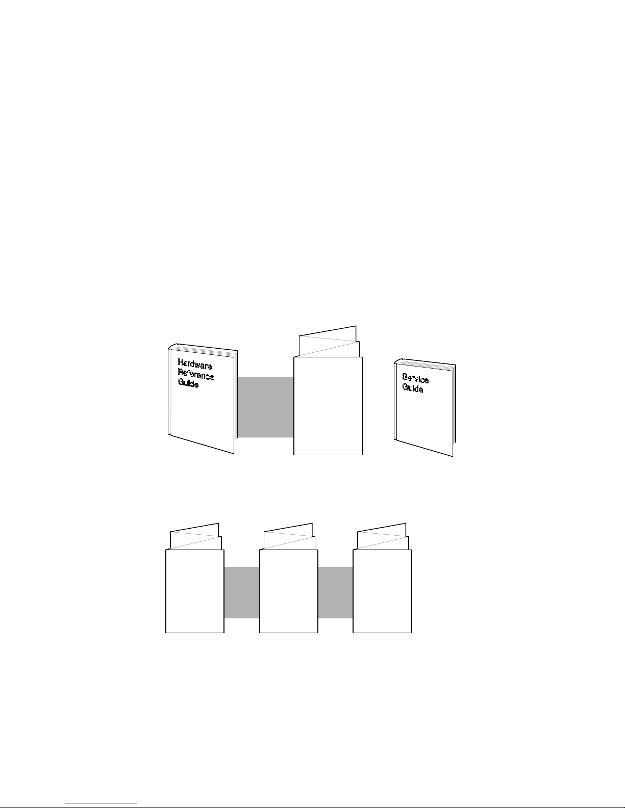
Figure 1 is a guide to the DEC 3000 Model 300 Series AXP
documentation.
Figure 1 Guide to DEC 3000 Model 300 Series AXP
Documentation
READ THIS
FIRST:
Setting up
Your System
To use a workstation,
and handle problems.
Adding
Memory
To get the system
set up and running,
and connect to a
network.
Adding a
RemovableMedia Drive
For Digital Services
personnel or customers.
Adding an
Internal Fixed
Disk Drive
MLO-011294
xv


Chapter Overview
1
Introduction to Your System
Introduction
In This Chapter
The DEC 3000 Model 300 Series AXP system is a
high-performance, desktop system that uses Digital’s
DECchip 21064 RISC-style microprocessor. Your new
DEC 3000 Model 300 Series AXP system is a member of a
family of powerful desktop systems based on the Digital Alpha
AXP architecture. It provides all the advantages of a 64-bit
computing environment and the choice of multiple operating
systems.
This chapter covers the following topics:
• Product Description
• Operating Systems
• Graphics Capabilities
• Integrated Services Digital Network (ISDN)
• Audio Capabilities
• System Personalization Capabilities
• Firmware Update Utility
1–1
Product Description
Product Description
System
Components
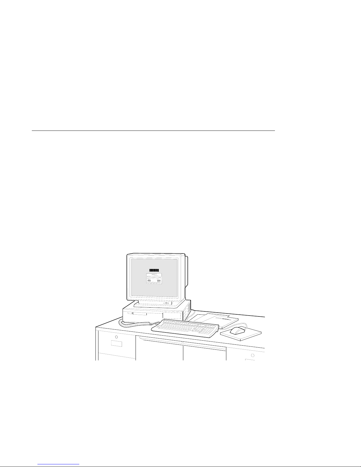
The DEC 3000 Model 300 Series AXP system consists of four
basic components:
• System unit
• Monitor
• Keyboard
• Mouse
Figure 1–1 shows the system and its components.
Figure 1–1 System Components
Model 300
Series Features
1–2
There are four variants of the DEC 3000 Model 300 series of
systems: the Models 300, 300X and 300LX with TURBOchannel
option support, and the Model 300L. Table 1–1 lists the features
of each system.
MLO-010619

Product Description
Table 1–1 System Features
Feature Models 300/300X/300LX Model 300L Order Number
Operating systems: DEC OSF/1 AXP;
CPU speed: 150 Mhz - model 300
TURBOchannel
options:
Monitor support: Monochrome 19"
Monitor resolution: 1280 x 1024 1024 x 768 –
Memory: 8-megabyte standard
OpenVMS AXP
125 Mhz - model 300LX
175 Mhz - model 300X
Two slots None Refer to Chapter 2
Monochrome 17"
Color 16"
Color 19"
One or two additional
monitors (requires up to
two TURBOchannel HX
options)
inline memory modules
(SIMMs), expandable to 64
megabytes in 16-megabyte
increments.
32-megabyte SIMMs
expandable to 256
megabytes in 64-megabyte
increments.
Same –
100 Mhz - model 300L
–
–
–
Monochrome 17"
Color 16"
–
Not available
Same MS16–BA
–
–
–
VR319–DA/D4
VRM17–HA/H4
VRC16–HA/H4
VRT19–HA/H4
MS16–DA
(continued on next page)
1–3

Product Description
Table 1–1 (Cont.) System Features
Feature Models 300/300X/300LX Model 300L Order Number
Graphics: Integral 8-plane 2D
graphics, 1280 x 1024
HX TURBOchannel option
2D TX
TURBOchannel option
(DEC OSF/1 AXP only)
PXG+ 8-plane 3D Z-buffer
(DEC OSF/1 AXP only)
PXG+ 24-plane 3D (DEC
OSF/1 AXP only)
8- to 24-plane
upgrade for PXG+
(DEC OSF/1 AXP only)
24-bit Z-buffer upgrade
for 8-plane PXG+
(DEC OSF/1 AXP only)
ZLX-M1 24-plane
3D Z-buffer
(DEC OSF/1 AXP only)
3D Denali graphics
(DEC OSF/1 AXP only)
Integral 8-plane 2D
graphics, 1024 x 768
Not available
Not available
Not available
Not available
Not available
Not available
Not available
PMAGB–BE/BF
PMAGB–JA/JB
PMAGB–DA/DB
PMAGB–EA/EB
PMAG–GB
PMAG–HA
PMAGC–AA
PEXGA–AA/BA
/CA
1–4
(continued on next page)

Product Description
Table 1–1 (Cont.) System Features
Feature Models 300/300X/300LX Model 300L Order Number
Network
connections:
Secure system
feature:
Audio technology: Telephone quality audio
10BASE-T (twisted-pair)
10 Mb/s Ethernet port
AUI or ThinWire
(10base2) connection using
a Digital-recommended
adapter
Industry-standard ISDN
port for voice and data
Additional system security
for limited access to
console functions
input/ output, including a
built-in speaker. Headset
available with some
models.
Same –
Same –
Same –
(continued on next page)
1–5

Product Description
Table 1–1 (Cont.) System Features
Feature Models 300/300X/300LX Model 300L Order Number
External SCSI-II
port:
Communications
port:
Battery backup
clock:
Internal devices: Two 3½-inch RZxx fixed
One on-board 5 MB/s SCSI
channel for both internal
and external devices (up
to two internal and five
external devices)
Optional dual SCSI
TURBOchannel module
25-pin synchronous/
asynchronous connection
to a printer, plotter,
modem, or console
terminal.
Battery-run backup
internal clocking
system for synchronous
operations.
disk drives: RZ25, RZ25L,
RZ26, RZ26L or optional
RZ28
or
One 3½-inch RZxx fixed
disk drive and one 3½-inch
RX26 removable-media
drive
Same
Not available
Same –
Same –
Same RZ25–EP
–
PMAZC–AA
RZ25L–EP
RZ26–EP
RZ26L–EP
RZ28–EP
RX26–FB
Future Options
Additional options for your system may be available at a later
time.
1–6

Operating Systems
Operating Systems
A Choice of
Operating
Systems
OpenVMS AXP
Digital’s Alpha AXP architecture supports multiple operating
systems for your DEC 3000 Model 300 Series AXP system.
This section gives a brief description of the operating systems
currently available for this product:
• OpenVMS AXP
• DEC OSF/1 AXP
Information about installation and operation of each operating
system is provided in system-specific software documentation.
The OpenVMS AXP operating system:
• Is a general-purpose, multiuser operating system that can be
used in many different environments for a wide variety of
applications.
• Promotes ease-of-use and improved programming
productivity, and facilitates system management.
• Offers a combination of commercial strength and open
system benefits, including the following:
integrated networking
system security
distributed computing
windowing capabilities
• Supports a large number of industry standards that facilitate
application portability and interoperability.
DEC OSF/1
AXP
The DEC OSF/1 AXP operating system complies with the OSF
Application Environment Specification (AES), which specifies
the interface to support applications that run on a variety of
hardware platforms.
1–7

Operating Systems
The DEC OSF/1 AXP operating system:
• Is Digital Equipment Corporation’s implementation of
the Open Software Foundation (OSF) operating system
components and Motif graphical user interface and
programming environment.
• Complies with standards and industry specifications,
including FIPS 151-1, POSIX (IEEE Std. 1003.1-1988),
XPG3 BASE branding, XTI, and AT&T System V Interface
Definition (SVID) Issue 2 (Base System and Kernel
Extensions).
• Is an advanced kernel architecture based on Carnegie Mellon
University’s Mach V2.5 kernel design with components from
Berkeley Software Distribution 4.3 (BSD) and other sources.
DEC OSF/1 AXP provides numerous features to assist
application programmers in developing applications that use
shared libraries, multithread support, and memory mapped
files.
Factory
Installed
Software
If there is a yellow sticker over the power connector on the
back of your system unit, your operating system is already
installed on an internal fixed disk. Depending on which
operating system you ordered, your wrokstation will start with
the OpenVMS AXP Factory Installed Software (FIS) procedure,
or the DEC OSF/1 AXP Initialization Transition (IT) program.
Refer to your factory-installed software instructions for:
• Startup procedures
• Examples of startup screens
• System prompts
• Password information
• Login information
1–8

Graphics Capabilities
Graphics Capabilities
The Model 300L
System
The Model
300/300X/300LX
Systems
All DEC 3000 Model 300 Series AXP systems are shipped with
an integral, high-performance, accelerated 2-D, 8-plane, color
graphics frame buffer on the system module. However, the
Model 300L does not support additional graphics heads; that is,
you cannot connect more than one monitor to the system.
Additional graphics capabilities are supported on the DEC 3000
Model 300 Series AXP systems; support is operating-system
specific.
• OpenVMS Operating System
If your DEC 3000 Model 300 Series AXP system is running
the OpenVMS AXP operating system, you can add one or two
two-dimensional (2D) HX graphics options in TURBOchannel
slots 0 and/or 1. This HX option provides additional 8-plane,
accelerated 2D graphics and windowing operations. You can
add two HX options and two additional monitors to expand
the display area. Information about setting up your system
to use more than one monitor is provided in the OpenVMS
Alpha Version 1.5 Upgrade and Installation Manual.)
1–9

Graphics Capabilities
• DEC OSF/1 Operating System
If your DEC 3000 Model 300 Series AXP system is running
the DEC OSF/1 AXP operating system, version 1.3B or
later, — the two-dimensional (2D) HX graphics option, the
two-dimensional (2D) TX graphics option, the 2D/3D ZLX
graphics options, or the 3D HX+ graphics option can be
installed in a TURBOchannel slot.
Adding either the HX option (for DEC OSF/1 AXP and
OpenVMS AXP), or adding either the HX+ or the TX option
(for DEC OSF/1 AXP only), allows you to expand the display
area. The TX option provides 8-bit and 24-bit accelerated
2D graphics, windowing operations, and a hardware cursor.
The HX+ option provides 8-bit and 24-bit accelerated 3D
graphics, windowing operations, and a hardware cursor.
Information about setting up your system to use more than
one monitor is provided in the DEC OSF/1 Guide to System
Administration.
Installation
Information
For information about installing graphics options in the Model
300/300X/300LX systems, see Chapter 2.
1–10

Integrated Services Digital Network (ISDN)
Integrated Services Digital Network (ISDN)
ISDN Not Yet
Available
Australian ISDN
Connections
ISDN
Capabilities
Though your DEC 3000 Model 300 Series AXP system can
provide ISDN capabilities, it is not as yet agency approved and
available for your DEC 3000 Model 300 Series AXP system.
When your system is shipped, a foam block covers the ISDN port
on the back of the system unit.
Once agency approval of ISDN for the DEC 3000 Model 300
Series AXP systems is granted, you will be contacted by your
Digital sales representative to inform you of ISDN certification.
When you are ready to install ISDN hardware, you must request
your Digital service representative install the required hardware.
The following information explains the ISDN capabilities for
your DEC 3000 Model 300 Series AXP system pending license
approval.
The ISDN interface in this equipment has not completed
Australian ISDN network connection certification testing and
as such does not have an AUSTEL permit for connection. In
Australia, it is an offense to connect nonpermitted devices to a
public telecommunications network and may attract a fine of up
to $12,000.
ISDN is a digital telecommunications network, providing
connectivity for voice and data applications.
Your DEC 3000 Model 300 Series AXP system includes an ISDN
Basic Rate S/T interface, which includes:
• Two 64 kilobits per second B channels for voice and data
transmission
• One 16 kilobits per second D channel for signaling and
control
Use of ISDN B
Channels
The B channels can be used for digitized voice, circuit-switched
data at up to 64 kilobits per second, or packet-switched data
transmission.
1–11

Integrated Services Digital Network (ISDN)
Use of ISDN D
Channels
The D channel uses a protocol standardized by the International
Telegraph and Telephone Consultative Committee (CCITT) for
setting up these D-Channel connections. The D channel can also
be used for low-speed packet transmission.
Audio Capabilities
Audio Feature
The DEC 3000 Model 300 Series AXP system features telephonequality audio input and output capabilities, including a built-in
speaker.
You can attach a microphone, headphone, handset, headset,
or externally-powered speakers to the audio port. Normally,
the RS232 audio port is used in asynchronous mode. However,
support for X.25 synchronous communications is available, but is
operating-system-dependent.
The port pinouts for the audio jack on the back of the system
unit are provided in Appendix C. Chapter 4 describes ISDN tests
that you can issue from console mode: for example, to repeat,
record and playback audio messages.
DECsound
Application
Audio
Conferencing
Software
1–12
The DECsound application, shipped with your system as part
of the DECwindows Motif for OpenVMS AXP software, is an
easy-to-use software application that lets you play back recorded
messages, record audio messages, mail recorded messages, and
include recorded messages in compound documents.
Multimedia Services software and the DECspin audio
conferencing software are also shipped with your system as
part of the DEC OSF/1 software. These free applications let
you take advantage of the voice-quality base audio on your
system. The audio headset (provided in the parts kit with some
models) is for you to use in the quiet of your office with these
new applications. See the information sheet provided with the
headset for instructions on how to start the applications.

System Personalization Capabilities
System Personalization Capabilities
Firmware
Parameters
Before You
Change
Parameters
Your system firmware includes commands and parameters that
you can change to suit your specific needs. You may change the
default settings for these parameters from console mode (>>>) by
entering the
to change, as described in the next table.
To change this... Use this command...
The action the console takes after a halt
The default boot device
The default diagnostic startup mode
Refer to Chapter 4 for the format and available settings for these
parameters.
Do not change any parameters without fully understanding the
effect that the change may have on your workstation. If you are
not sure about changing parameters, ask your system manager
for assistance, or your Digital service representative.
set
command followed by the parameter you want
set
auto_action
set
bootdef_dev
set
diag_quick
1–13

Firmware Update Utility
Firmware Update Utility
Purpose
Write-Protecting
the Flash ROM
Digital Equipment Corporation distributes new Firmware
Update utility software whenever there are any changes to the
console firmware. The utility provides new firmware for the flash
ROM (read-only memory) in your system, including the console
program and diagnostic testing capabilities.
Note
Refer to the release notes you receive with the software
update for an explanation of how to use the Firmware
Update Utility software.
For your convenience, your system is shipped from the factory
with the flash ROM write jumper, labeled W1 on the system
module, in the write-enabled position. Thus, there is no need
to remove the system unit cover and get inside the system unit.
You can update your console firmware with the latest version
using the release notes.
To write-protect the flash ROM so that it cannot be overwritten:
1. Open the system unit cover.
Caution
To avoid possible product damage, refer to Chapter 2 for
instructions on how to power off the system, open, and
work inside your system unit.
2. Locate the W1 jumper shown in Figure 1–2.
The default write-enabled position of the jumper is on pins 2
and 3.
1–14
 Loading...