

Digital Equipment 21143 Reference Manual

Digital Semiconductor 21143
PCI/Car dBu s 10 /1 00-M b/s Et her net
LAN Co ntro lle r
Hardware Reference Manual
Order Number: EC–QWC4D–TE
Revision/Update Information: This manual supersedes the Digital Semiconductor
21143 PCI/CardBus 10/100-Mb/s Ethernet LAN
Controller Hardware Reference Manual
(EC–QWC4C–TE).
Digital Equi pm e n t Co rpo ra ti on
Maynard, Massachusetts
http://www.digital.com/semiconductor

May 199 7
While DIGITAL believes the information included in this publication is correct as of the date of publication, it is
subject to change without notice.
Digital Equipment Corporation makes no representations that the use of its products in the manner described in this
publicat ion will not infringe on exist ing or future patent rights, nor do the descrip ti ons containe d in this publication
imply the granting of licens es to make, use, or sel l equipment or softw ar e in accordance with the description.
©Digita l Equipment Corporation 1997. All rights reserved.
Printed in U.S.A.
DIGITAL, D igital Semicondu ctor, SecureON, and the DIGITAL logo ar e trademarks of Digi tal Equipment
Corporat ion.
CardBus is a trademark of Personal Computer Memory Card International Association.
IEEE is a register ed trademark of The Ins titute of Electrical and Electronics Engineers, Inc.
Magic Packet is a t rademark of Advanced Micro Devices, In c.
MicroWire i s a reg ist ered trademark of BankAmerica Corporation.
All other trad emarks and register ed trademarks are th e pr operty of their respective owners.

Contents
Preface
1 Introduction
1.1 General Description . . . . . . . . . . . . . . . . . . . . . . . . . . . . . . . . . . . . . . . . . . . . . . . 1–1
1.2 Features . . . . . . . . . . . . . . . . . . . . . . . . . . . . . . . . . . . . . . . . . . . . . . . . . . . . . . . . 1–2
1.3 Microarchitecture . . . . . . . . . . . . . . . . . . . . . . . . . . . . . . . . . . . . . . . . . . . . . . . . . 1–3
2 Signal Descriptions
2.1 21143 Pinout. . . . . . . . . . . . . . . . . . . . . . . . . . . . . . . . . . . . . . . . . . . . . . . . . . . . . 2–1
2.2 Signal Descriptions . . . . . . . . . . . . . . . . . . . . . . . . . . . . . . . . . . . . . . . . . . . . . . . . 2–3
3 Registers
3.1 Configuration Operation. . . . . . . . . . . . . . . . . . . . . . . . . . . . . . . . . . . . . . . . . . . . 3–1
3.1.1 Configuration Register Mapping . . . . . . . . . . . . . . . . . . . . . . . . . . . . . . . . . . 3–2
3.1.2 Configuration Registers . . . . . . . . . . . . . . . . . . . . . . . . . . . . . . . . . . . . . . . . . 3–3
3.1.2.1 Configuration ID Register (CFID–Offset 00H) . . . . . . . . . . . . . . . . . . . . 3–3
3.1.2.2 Command and Status Configuration Register (CFCS–Offset 04H) . . . . 3–4
3.1.2.3 Configuration Revision Register (CFRV–Offset 08H). . . . . . . . . . . . . . . 3–7
3.1.2.4 Configuration Latency Timer Register (CFLT–Offset 0CH) . . . . . . . . . . 3–8
3.1.2.5 Configuration Base I/O Address Register (CBIO–Offset 10H) . . . . . . . . 3–9
3.1.2.6 Configuration Base Memory Address Regist er (CBMA–Offset 14H) . . . 3–10
3.1.2.7 Configuration Card Information Structure Register (CCI S–Offset 28H). 3–11
3.1.2.8 Subsystem ID Regi ster (CSID–Offset 2CH). . . . . . . . . . . . . . . . . . . . . . 3–12
3.1.2.9 Expansion ROM Base Address Register (CBER–Offset 30H). . . . . . . . 3–13
3.1.2.10 Configuration Interrupt Register (CFI T–O ff set 3CH) . . . . . . . . . . . . . . . 3–14
3.1.2.11 Configuration Device and Driver Area Register (CFDD–Offset 40H). . . 3–15
3.2 CSR Operation . . . . . . . . . . . . . . . . . . . . . . . . . . . . . . . . . . . . . . . . . . . . . . . . . . . 3–17
3.2.1 Control and Stat us Register Mapping . . . . . . . . . . . . . . . . . . . . . . . . . . . . . . 3–17
iii

3.2.2 Host CSRs. . . . . . . . . . . . . . . . . . . . . . . . . . . . . . . . . . . . . . . . . . . . . . . . . . . 3–18
3.2.2.1 Bus Mode Register (CSR0–Of fset 00H). . . . . . . . . . . . . . . . . . . . . . . . . 3–18
3.2.2.2 Transmit Poll Demand Register (CSR1–Offset 08H) . . . . . . . . . . . . . . . 3–22
3.2.2.3 Receive Poll Demand Register (CSR2–Offset 10H). . . . . . . . . . . . . . . . 3–23
3.2.2.4 Descriptor List Base Address Registers (CSR3–Offset 18H and
CSR4–Offset 20H) . . . . . . . . . . . . . . . . . . . . . . . . . . . . . . . . . . . . . . . . . 3–23
3.2.2.5 Status Register (CSR5–Offset 28H). . . . . . . . . . . . . . . . . . . . . . . . . . . . 3–25
3.2.2.6 Operation Mode Register (CSR6–Offset 30H). . . . . . . . . . . . . . . . . . . . 3–33
3.2.2.7 Interrupt Enable Register (CSR7–Offset 38H). . . . . . . . . . . . . . . . . . . . 3–41
3.2.2.8 Missed Frames and Over flow Counter Register (CSR8–Offset 40H). . . 3–45
3.2.2.9 Boot ROM, Serial ROM, and MII Management Register
(CSR9–Offset 48H) . . . . . . . . . . . . . . . . . . . . . . . . . . . . . . . . . . . . . . . . 3–46
3.2.2.10 Boot ROM Programming Address Register (CSR10–Offset 50H) . . . . . 3–49
3.2.2.11 General-Purpose Timer Register (CSR11–Of fset 58H). . . . . . . . . . . . . 3–50
3.2.2.12 SIA Status Register ( CSR12–O ffset 60H) . . . . . . . . . . . . . . . . . . . . . . . 3–51
3.2.2.13 SIA Connectivity Register (CSR13–Offset 68H). . . . . . . . . . . . . . . . . . . 3–54
3.2.2.14 SIA Transmit and Recei ve Register (CSR14–Offset 70H) . . . . . . . . . . . 3–55
3.2.2.15 SIA and General-Purpose Port Register (CSR15–Offset 78H) . . . . . . . 3–60
3.2.2.16 SIA and MII Operatin g Mod es . . . . . . . . . . . . . . . . . . . . . . . . . . . . . . . . 3–64
4 Host Communication
4.1 Data Communication . . . . . . . . . . . . . . . . . . . . . . . . . . . . . . . . . . . . . . . . . . . . . . 4–1
4.2 Descriptor Lists and Data Buffers. . . . . . . . . . . . . . . . . . . . . . . . . . . . . . . . . . . . . 4–1
4.2.1 Receive Descriptors. . . . . . . . . . . . . . . . . . . . . . . . . . . . . . . . . . . . . . . . . . . . 4–3
4.2.1.1 Receive Descriptor 0 (RDES0). . . . . . . . . . . . . . . . . . . . . . . . . . . . . . . . 4–4
4.2.1.2 Receive Descriptor 1 (RDES1). . . . . . . . . . . . . . . . . . . . . . . . . . . . . . . . 4–8
4.2.1.3 Receive Descriptor 2 (RDES2). . . . . . . . . . . . . . . . . . . . . . . . . . . . . . . . 4–9
4.2.1.4 Receive Descriptor 3 (RDES3). . . . . . . . . . . . . . . . . . . . . . . . . . . . . . . . 4–9
4.2.1.5 Receive Descriptor Status Validity. . . . . . . . . . . . . . . . . . . . . . . . . . . . . 4–10
4.2.2 Transmit Descriptors . . . . . . . . . . . . . . . . . . . . . . . . . . . . . . . . . . . . . . . . . . . 4–10
4.2.2.1 Transmit Descriptor 0 (TDES0) . . . . . . . . . . . . . . . . . . . . . . . . . . . . . . . 4–11
4.2.2.2 Transmit Descriptor 1 (TDES1) . . . . . . . . . . . . . . . . . . . . . . . . . . . . . . . 4–14
4.2.2.3 Transmit Descriptor 2 (TDES2) . . . . . . . . . . . . . . . . . . . . . . . . . . . . . . . 4–17
4.2.2.4 Transmit Descriptor 3 (TDES3) . . . . . . . . . . . . . . . . . . . . . . . . . . . . . . . 4–17
4.2.2.5 Transmit Descri ptor Status Validit y . . . . . . . . . . . . . . . . . . . . . . . . . . . . 4–18
4.2.3 Setup Frame . . . . . . . . . . . . . . . . . . . . . . . . . . . . . . . . . . . . . . . . . . . . . . . . . 4–18
4.2.3.1 First Setup Fra me. . . . . . . . . . . . . . . . . . . . . . . . . . . . . . . . . . . . . . . . . . 4–19
4.2.3.2 Subsequent Setup Frames. . . . . . . . . . . . . . . . . . . . . . . . . . . . . . . . . . . 4–19
4.2.3.3 Perfect Fil ter ing Setup Frame Buffer . . . . . . . . . . . . . . . . . . . . . . . . . . . 4–19
4.2.3.4 Imperfect Fi ltering Setup Frame Buffer . . . . . . . . . . . . . . . . . . . . . . . . . 4–22
4.3 Functional Description . . . . . . . . . . . . . . . . . . . . . . . . . . . . . . . . . . . . . . . . . . . . . 4–27
4.3.1 Reset Commands . . . . . . . . . . . . . . . . . . . . . . . . . . . . . . . . . . . . . . . . . . . . . 4–27
4.3.2 Power-Saving Modes. . . . . . . . . . . . . . . . . . . . . . . . . . . . . . . . . . . . . . . . . . . 4–28
4.3.2.1 Sleep Power-Saving Mode. . . . . . . . . . . . . . . . . . . . . . . . . . . . . . . . . . . 4–28
iv

4.3.2.2 Snooze Power-Saving Mode . . . . . . . . . . . . . . . . . . . . . . . . . . . . . . . . . 4–29
4.3.3 Arbitrat ion Scheme . . . . . . . . . . . . . . . . . . . . . . . . . . . . . . . . . . . . . . . . . . . . 4–30
4.3.4 Interrupts . . . . . . . . . . . . . . . . . . . . . . . . . . . . . . . . . . . . . . . . . . . . . . . . . . . . 4–32
4.3.5 Startup Procedure . . . . . . . . . . . . . . . . . . . . . . . . . . . . . . . . . . . . . . . . . . . . . 4–33
4.3.6 Receive Process . . . . . . . . . . . . . . . . . . . . . . . . . . . . . . . . . . . . . . . . . . . . . . 4–34
4.3.6.1 Descriptor Acquisition. . . . . . . . . . . . . . . . . . . . . . . . . . . . . . . . . . . . . . . 4–34
4.3.6.2 Frame Processing . . . . . . . . . . . . . . . . . . . . . . . . . . . . . . . . . . . . . . . . . 4–34
4.3.6.3 Receive Process Suspended . . . . . . . . . . . . . . . . . . . . . . . . . . . . . . . . . 4–35
4.3.6.4 Receive Process State Transitions. . . . . . . . . . . . . . . . . . . . . . . . . . . . . 4–36
4.3.7 Transmit Process. . . . . . . . . . . . . . . . . . . . . . . . . . . . . . . . . . . . . . . . . . . . . . 4–37
4.3.7.1 Frame Processing . . . . . . . . . . . . . . . . . . . . . . . . . . . . . . . . . . . . . . . . . 4–37
4.3.7.2 Transmit Poll ing Suspended. . . . . . . . . . . . . . . . . . . . . . . . . . . . . . . . . . 4–38
4.3.7.3 Transmit Process State Transitions . . . . . . . . . . . . . . . . . . . . . . . . . . . . 4–39
5 Host Bus Operation
5.1 Overview. . . . . . . . . . . . . . . . . . . . . . . . . . . . . . . . . . . . . . . . . . . . . . . . . . . . . . . . 5–1
5.2 Bus Commands . . . . . . . . . . . . . . . . . . . . . . . . . . . . . . . . . . . . . . . . . . . . . . . . . . 5–2
5.3 Bus Slave Operation . . . . . . . . . . . . . . . . . . . . . . . . . . . . . . . . . . . . . . . . . . . . . . . 5–2
5.3.1 Slave Read Cycle (I/O or Memory Target). . . . . . . . . . . . . . . . . . . . . . . . . . . 5–3
5.3.2 Slave Write Cycle (I/O or Memory Target). . . . . . . . . . . . . . . . . . . . . . . . . . . 5–4
5.3.3 Configuration Read and Write Cycles . . . . . . . . . . . . . . . . . . . . . . . . . . . . . . 5–5
5.4 Bus Master Operation. . . . . . . . . . . . . . . . . . . . . . . . . . . . . . . . . . . . . . . . . . . . . . 5–6
5.4.1 Bus Arbitration . . . . . . . . . . . . . . . . . . . . . . . . . . . . . . . . . . . . . . . . . . . . . . . . 5–7
5.4.2 Memory Read Cycle . . . . . . . . . . . . . . . . . . . . . . . . . . . . . . . . . . . . . . . . . . . 5–8
5.4.3 Memory Write Cycle . . . . . . . . . . . . . . . . . . . . . . . . . . . . . . . . . . . . . . . . . . . 5–9
5.5 Termination Cycles. . . . . . . . . . . . . . . . . . . . . . . . . . . . . . . . . . . . . . . . . . . . . . . . 5–10
5.5.1 Slave-Ini ti ated Termination . . . . . . . . . . . . . . . . . . . . . . . . . . . . . . . . . . . . . . 5–10
5.5.1.1 Disconnect Termination . . . . . . . . . . . . . . . . . . . . . . . . . . . . . . . . . . . . . 5–11
5.5.1.2 Retry Termination. . . . . . . . . . . . . . . . . . . . . . . . . . . . . . . . . . . . . . . . . . 5–12
5.5.2 Master-Ini ti ated Termination . . . . . . . . . . . . . . . . . . . . . . . . . . . . . . . . . . . . . 5–13
5.5.2.1 21143-Init iated Termination . . . . . . . . . . . . . . . . . . . . . . . . . . . . . . . . . . 5–13
5.5.2.2 Memory-Controller-Initiated Termination . . . . . . . . . . . . . . . . . . . . . . . . 5–15
5.6 Parity. . . . . . . . . . . . . . . . . . . . . . . . . . . . . . . . . . . . . . . . . . . . . . . . . . . . . . . . . . . 5–18
5.7 Parking . . . . . . . . . . . . . . . . . . . . . . . . . . . . . . . . . . . . . . . . . . . . . . . . . . . . . . . . . 5–19
6 Network Interface Operation
6.1 MII/SYM Port. . . . . . . . . . . . . . . . . . . . . . . . . . . . . . . . . . . . . . . . . . . . . . . . . . . . . 6–1
6.1.1 100BASE-T Terminology. . . . . . . . . . . . . . . . . . . . . . . . . . . . . . . . . . . . . . . . 6–1
6.1.2 Interface Description . . . . . . . . . . . . . . . . . . . . . . . . . . . . . . . . . . . . . . . . . . . 6–2
6.1.2.1 Signal Standards . . . . . . . . . . . . . . . . . . . . . . . . . . . . . . . . . . . . . . . . . . 6–2
6.1.2.2 Operating Modes . . . . . . . . . . . . . . . . . . . . . . . . . . . . . . . . . . . . . . . . . . 6–4
6.2 10BASE-T and AUI Functions . . . . . . . . . . . . . . . . . . . . . . . . . . . . . . . . . . . . . . . 6–5
v

6.2.1 Receivers and Drivers . . . . . . . . . . . . . . . . . . . . . . . . . . . . . . . . . . . . . . . . . . 6–6
6.2.2 Manchester Decoder. . . . . . . . . . . . . . . . . . . . . . . . . . . . . . . . . . . . . . . . . . . 6–6
6.2.3 Manchester Encoder . . . . . . . . . . . . . . . . . . . . . . . . . . . . . . . . . . . . . . . . . . . 6–6
6.2.4 Oscillator Circuitry . . . . . . . . . . . . . . . . . . . . . . . . . . . . . . . . . . . . . . . . . . . . . 6–6
6.2.5 Smart Squelch . . . . . . . . . . . . . . . . . . . . . . . . . . . . . . . . . . . . . . . . . . . . . . . . 6–7
6.2.6 Autopolarity Detector . . . . . . . . . . . . . . . . . . . . . . . . . . . . . . . . . . . . . . . . . . . 6–7
6.2.7 Network Port Autosensing . . . . . . . . . . . . . . . . . . . . . . . . . . . . . . . . . . . . . . . 6–8
6.2.8 10BASE-T Link Integri ty Test . . . . . . . . . . . . . . . . . . . . . . . . . . . . . . . . . . . . 6–9
6.3 Media Access Control Operation . . . . . . . . . . . . . . . . . . . . . . . . . . . . . . . . . . . . . 6–9
6.3.1 MAC Frame Format . . . . . . . . . . . . . . . . . . . . . . . . . . . . . . . . . . . . . . . . . . . . 6–9
6.3.1.1 Ethernet and IEEE 802.3 Frames. . . . . . . . . . . . . . . . . . . . . . . . . . . . . . 6–10
6.3.1.2 Ethernet Frame Format Description. . . . . . . . . . . . . . . . . . . . . . . . . . . . 6–10
6.3.2 Ethernet Recept ion Addressing. . . . . . . . . . . . . . . . . . . . . . . . . . . . . . . . . . . 6–12
6.3.3 Detailed Tran sm it Op eration . . . . . . . . . . . . . . . . . . . . . . . . . . . . . . . . . . . . . 6–13
6.3.3.1 Transmit Ini tiation. . . . . . . . . . . . . . . . . . . . . . . . . . . . . . . . . . . . . . . . . . 6–13
6.3.3.2 Frame Encapsul ati on . . . . . . . . . . . . . . . . . . . . . . . . . . . . . . . . . . . . . . . 6–14
6.3.3.3 Initial Deferral . . . . . . . . . . . . . . . . . . . . . . . . . . . . . . . . . . . . . . . . . . . . . 6–14
6.3.3.4 Collisio n . . . . . . . . . . . . . . . . . . . . . . . . . . . . . . . . . . . . . . . . . . . . . . . . . 6–15
6.3.3.5 Terminating Transmission . . . . . . . . . . . . . . . . . . . . . . . . . . . . . . . . . . . 6–15
6.3.3.6 Transmit Parameter Values . . . . . . . . . . . . . . . . . . . . . . . . . . . . . . . . . . 6–16
6.3.4 Detailed Recei ve O peration. . . . . . . . . . . . . . . . . . . . . . . . . . . . . . . . . . . . . . 6–17
6.3.4.1 Receive Init iation . . . . . . . . . . . . . . . . . . . . . . . . . . . . . . . . . . . . . . . . . . 6–17
6.3.4.2 Preamble Processing . . . . . . . . . . . . . . . . . . . . . . . . . . . . . . . . . . . . . . . 6–17
6.3.4.2.1 MII/SYM, 10BASE-T, or AUI Mode Preambles. . . . . . . . . . . . . . . . 6–17
6.3.4.2.2 100BASE-TX or 100BASE-FX Mode Preambles . . . . . . . . . . . . . . 6–18
6.3.4.3 Address Match ing. . . . . . . . . . . . . . . . . . . . . . . . . . . . . . . . . . . . . . . . . . 6–18
6.3.4.4 Frame Decapsul ati on. . . . . . . . . . . . . . . . . . . . . . . . . . . . . . . . . . . . . . . 6–19
6.3.4.5 Terminating Reception . . . . . . . . . . . . . . . . . . . . . . . . . . . . . . . . . . . . . . 6–19
6.3.4.6 Frame Reception Status. . . . . . . . . . . . . . . . . . . . . . . . . . . . . . . . . . . . . 6–20
6.4 Loopback Operations . . . . . . . . . . . . . . . . . . . . . . . . . . . . . . . . . . . . . . . . . . . . . . 6–21
6.4.1 Internal Loo pback Mode . . . . . . . . . . . . . . . . . . . . . . . . . . . . . . . . . . . . . . . . 6–21
6.4.2 External Loopback Mode. . . . . . . . . . . . . . . . . . . . . . . . . . . . . . . . . . . . . . . . 6–22
6.4.3 Driver Enter ing Loopback Mode . . . . . . . . . . . . . . . . . . . . . . . . . . . . . . . . . . 6–22
6.4.4 Driver Restor ing Normal Operation . . . . . . . . . . . . . . . . . . . . . . . . . . . . . . . . 6–23
6.5 Full-Duplex Operation. . . . . . . . . . . . . . . . . . . . . . . . . . . . . . . . . . . . . . . . . . . . . . 6–24
6.6 Autonegotiation. . . . . . . . . . . . . . . . . . . . . . . . . . . . . . . . . . . . . . . . . . . . . . . . . . . 6–25
6.7 Capture Effect–A Value-Added Feature . . . . . . . . . . . . . . . . . . . . . . . . . . . . . . . . 6–26
6.7.1 What Is Capture Effect?. . . . . . . . . . . . . . . . . . . . . . . . . . . . . . . . . . . . . . . . . 6–26
6.7.2 Resolving Capture Effect. . . . . . . . . . . . . . . . . . . . . . . . . . . . . . . . . . . . . . . . 6–28
6.7.3 Enhanced Resolution for Capture Effect . . . . . . . . . . . . . . . . . . . . . . . . . . . . 6–29
6.8 Jabber and Watchdog Timers. . . . . . . . . . . . . . . . . . . . . . . . . . . . . . . . . . . . . . . . 6–29
7 Extern al Po rt s
7.1 Overview. . . . . . . . . . . . . . . . . . . . . . . . . . . . . . . . . . . . . . . . . . . . . . . . . . . . . . . . 7–1
vi

7.2 Boot ROM and Serial ROM Connection . . . . . . . . . . . . . . . . . . . . . . . . . . . . . . . . 7–1
7.3 Boot ROM Operations. . . . . . . . . . . . . . . . . . . . . . . . . . . . . . . . . . . . . . . . . . . . . . 7–3
7.3.1 Byte Read . . . . . . . . . . . . . . . . . . . . . . . . . . . . . . . . . . . . . . . . . . . . . . . . . . . 7–3
7.3.2 Byte Write . . . . . . . . . . . . . . . . . . . . . . . . . . . . . . . . . . . . . . . . . . . . . . . . . . . 7–4
7.3.3 Dword Read. . . . . . . . . . . . . . . . . . . . . . . . . . . . . . . . . . . . . . . . . . . . . . . . . . 7–5
7.4 Serial ROM Operations. . . . . . . . . . . . . . . . . . . . . . . . . . . . . . . . . . . . . . . . . . . . . 7–6
7.4.1 Read Operation . . . . . . . . . . . . . . . . . . . . . . . . . . . . . . . . . . . . . . . . . . . . . . . 7–7
7.4.2 Write Operati on . . . . . . . . . . . . . . . . . . . . . . . . . . . . . . . . . . . . . . . . . . . . . . . 7–10
7.5 External Register Operation . . . . . . . . . . . . . . . . . . . . . . . . . . . . . . . . . . . . . . . . . 7–13
7.6 General-Purpose Port and LEDs . . . . . . . . . . . . . . . . . . . . . . . . . . . . . . . . . . . . . 7–14
8 Remotely Waking Up the LAN
8.1 Overview. . . . . . . . . . . . . . . . . . . . . . . . . . . . . . . . . . . . . . . . . . . . . . . . . . . . . . . . 8–1
8.2 Remote Wake-Up Controller Block Diagram. . . . . . . . . . . . . . . . . . . . . . . . . . . . . 8–1
8.3 Remote Wake-Up-LAN Operation. . . . . . . . . . . . . . . . . . . . . . . . . . . . . . . . . . . . . 8–3
8.3.1 Remote Wake-Up-LAN Mode with Main System Power Off . . . . . . . . . . . . . 8–3
8.3.2 Remote Wake-Up-LAN Mode with Main System Power On . . . . . . . . . . . . . 8–4
8.4 Invalid Password Limiter . . . . . . . . . . . . . . . . . . . . . . . . . . . . . . . . . . . . . . . . . . . . 8–5
8.5 Config uration Revision Register (CFRV–Offset 08H). . . . . . . . . . . . . . . . . . . . . . 8–5
8.6 SIA and General-Purpose Por t Register (CSR15–Offse t 78H). . . . . . . . . . . . . . . 8–7
8.7 PCI Configuration Register s. . . . . . . . . . . . . . . . . . . . . . . . . . . . . . . . . . . . . . . . . 8–11
8.7.1 Configurat ion Wake-Up-LAN IEEE Address 0 Register
(CWUA0–Offset 44H) . . . . . . . . . . . . . . . . . . . . . . . . . . . . . . . . . . . . . . . . . . 8–12
8.7.2 Configurat ion Wake-Up-LAN IEEE Address 1 Register
(CWUA1–Offset 48H) . . . . . . . . . . . . . . . . . . . . . . . . . . . . . . . . . . . . . . . . . . 8–14
8.7.3 Configurat ion Wake-Up Command Register (CWUC–Offset 54H) . . . . . . . . 8–15
8.7.4 SecureON™ Password Register (SOP0–Offset 4CH). . . . . . . . . . . . . . . . . . 8–17
8.7.5 SecureON Password Regis ter (SOP 1–Offset 50H). . . . . . . . . . . . . . . . . . . . 8–18
8.8 Remote Wake-Up-LAN Data Block in t he SROM. . . . . . . . . . . . . . . . . . . . . . . . . 8–20
8.8.1 Remote Wake-Up-LAN IEEE Addres s and Command (SROM) . . . . . . . . . . 8–21
8.9 21143 Magic Packet Format. . . . . . . . . . . . . . . . . . . . . . . . . . . . . . . . . . . . . . . . . 8–24
A Joint Test Action Group—Test Logic
A.1 General Description . . . . . . . . . . . . . . . . . . . . . . . . . . . . . . . . . . . . . . . . . . . . . . . A–1
A.2 Registers. . . . . . . . . . . . . . . . . . . . . . . . . . . . . . . . . . . . . . . . . . . . . . . . . . . . . . . . A–2
A.2.1 Instruction Register . . . . . . . . . . . . . . . . . . . . . . . . . . . . . . . . . . . . . . . . . . . . A–2
A.2.2 Bypass Register. . . . . . . . . . . . . . . . . . . . . . . . . . . . . . . . . . . . . . . . . . . . . . . A–3
A.2.3 Boundary-Scan Register . . . . . . . . . . . . . . . . . . . . . . . . . . . . . . . . . . . . . . . . A–3
A.2.4 Test Access Port Controller. . . . . . . . . . . . . . . . . . . . . . . . . . . . . . . . . . . . . . A–4
vii

B DNA CSMA/CD Counters and Events Support
B.1 CSMA/CD Counters . . . . . . . . . . . . . . . . . . . . . . . . . . . . . . . . . . . . . . . . . . . . . . . B–1
C Hash C Routine
C.1 Little Endian Architecture Hash C Routine . . . . . . . . . . . . . . . . . . . . . . . . . . . . . . C–1
C.2 Big Endian Architecture Hash C Routine . . . . . . . . . . . . . . . . . . . . . . . . . . . . . . . C–1
D Port Selection Procedure
D.1 MII Port Selection . . . . . . . . . . . . . . . . . . . . . . . . . . . . . . . . . . . . . . . . . . . . . . . . . D–1
D.2 SYM Port Selection. . . . . . . . . . . . . . . . . . . . . . . . . . . . . . . . . . . . . . . . . . . . . . . . D–2
D.3 10BASE-T Port Selection . . . . . . . . . . . . . . . . . . . . . . . . . . . . . . . . . . . . . . . . . . . D–2
D.4 AUI Port Selection. . . . . . . . . . . . . . . . . . . . . . . . . . . . . . . . . . . . . . . . . . . . . . . . . D–3
E General-Purpose Port and LED Programming
E.1 Input Port Selection with Interrupt. . . . . . . . . . . . . . . . . . . . . . . . . . . . . . . . . . . . . E–1
E.2 Input Port Selection Without Interrupt. . . . . . . . . . . . . . . . . . . . . . . . . . . . . . . . . . E–1
E.3 Output Port Selection . . . . . . . . . . . . . . . . . . . . . . . . . . . . . . . . . . . . . . . . . . . . . . E–2
E.4 LED/Control Selection. . . . . . . . . . . . . . . . . . . . . . . . . . . . . . . . . . . . . . . . . . . . . . E–2
F Support, Products, and Documentation
Index
viii

Examples
4–1 Perfect Filtering Buffer........................................................................................... 4–21
4–2 Imperfect Filtering Buffer....................................................................................... 4–24
8–1 21143 Magic Packet Fields... .. .......... .. .................... .. .......... .. .................... .. .......... 8–25
ix

Figures
1–1 21143 Block Diagram . . . . . . . . . . . . . . . . . . . . . . . . . . . . . . . . . . . . . . . . . . . . . . 1–5
2–1 21143 Pin out Diagram (Top View) . . . . . . . . . . . . . . . . . . . . . . . . . . . . . . . . . . . . 2–2
3–1 CFID Register Bit Fields . . . . . . . . . . . . . . . . . . . . . . . . . . . . . . . . . . . . . . . . . . . . 3–3
3–2 CFCS Register Bit Fields . . . . . . . . . . . . . . . . . . . . . . . . . . . . . . . . . . . . . . . . . . . 3–4
3–3 CFRV Register Bit Fields . . . . . . . . . . . . . . . . . . . . . . . . . . . . . . . . . . . . . . . . . . . 3–7
3–4 CFLT Configuration Latency Timer Register. . . . . . . . . . . . . . . . . . . . . . . . . . . . . 3–8
3–5 CBIO Register Bit Fields. . . . . . . . . . . . . . . . . . . . . . . . . . . . . . . . . . . . . . . . . . . . 3–9
3–6 CBMA Register Bit Fields . . . . . . . . . . . . . . . . . . . . . . . . . . . . . . . . . . . . . . . . . . . 3–10
3–7 CCIS Register Bit Fields. . . . . . . . . . . . . . . . . . . . . . . . . . . . . . . . . . . . . . . . . . . . 3–11
3–8 CSID Regis ter Bit Fiel ds. . . . . . . . . . . . . . . . . . . . . . . . . . . . . . . . . . . . . . . . . . . . 3–12
3–9 CBER Regist er Bi t Fi elds . . . . . . . . . . . . . . . . . . . . . . . . . . . . . . . . . . . . . . . . . . . 3–13
3–10 CFIT Register Bit Fields . . . . . . . . . . . . . . . . . . . . . . . . . . . . . . . . . . . . . . . . . . . . 3–14
3–11 CFDD Register Bit Fields . . . . . . . . . . . . . . . . . . . . . . . . . . . . . . . . . . . . . . . . . . . 3–15
3–12 CSR0 Bus Mode Register. . . . . . . . . . . . . . . . . . . . . . . . . . . . . . . . . . . . . . . . . . . 3–18
3–13 CSR1 Register Bit Field . . . . . . . . . . . . . . . . . . . . . . . . . . . . . . . . . . . . . . . . . . . . 3–22
3–14 CSR2 Register Bit Field . . . . . . . . . . . . . . . . . . . . . . . . . . . . . . . . . . . . . . . . . . . . 3–23
3–15 CSR3 Register Bit Field . . . . . . . . . . . . . . . . . . . . . . . . . . . . . . . . . . . . . . . . . . . . 3–24
3–16 CSR4 Register Bit Field . . . . . . . . . . . . . . . . . . . . . . . . . . . . . . . . . . . . . . . . . . . . 3–25
3–17 CSR5 Register Bit Fields . . . . . . . . . . . . . . . . . . . . . . . . . . . . . . . . . . . . . . . . . . . 3–26
3–18 CSR6 Register Bit Fields . . . . . . . . . . . . . . . . . . . . . . . . . . . . . . . . . . . . . . . . . . . 3–33
3–19 CSR7 Register Bit Fields . . . . . . . . . . . . . . . . . . . . . . . . . . . . . . . . . . . . . . . . . . . 3–41
3–20 CSR8 Missed Frames and Overflow Counter. . . . . . . . . . . . . . . . . . . . . . . . . . . . 3–45
3–21 CSR9 Register Bit Fields . . . . . . . . . . . . . . . . . . . . . . . . . . . . . . . . . . . . . . . . . . . 3–47
3–22 CSR10 Register Bit Field . . . . . . . . . . . . . . . . . . . . . . . . . . . . . . . . . . . . . . . . . . . 3–49
3–23 CSR11 Register Bit Fields . . . . . . . . . . . . . . . . . . . . . . . . . . . . . . . . . . . . . . . . . . 3–50
3–24 CSR12 Register Bit Fields . . . . . . . . . . . . . . . . . . . . . . . . . . . . . . . . . . . . . . . . . . 3–51
3–25 CSR13 Register Bit Fields . . . . . . . . . . . . . . . . . . . . . . . . . . . . . . . . . . . . . . . . . . 3–54
3–26 CSR14 Register Bit Fields . . . . . . . . . . . . . . . . . . . . . . . . . . . . . . . . . . . . . . . . . . 3–55
3–27 CSR15 Register Bit Fields . . . . . . . . . . . . . . . . . . . . . . . . . . . . . . . . . . . . . . . . . . 3–60
4–1 Descriptor Ring and Chain Struct ure Examples . . . . . . . . . . . . . . . . . . . . . . . . . . 4–2
4–2 Receive Descriptor Format . . . . . . . . . . . . . . . . . . . . . . . . . . . . . . . . . . . . . . . . . . 4–3
4–3 RDES0 Bit Fields . . . . . . . . . . . . . . . . . . . . . . . . . . . . . . . . . . . . . . . . . . . . . . . . . 4–4
4–4 RDES1 Bit Fields . . . . . . . . . . . . . . . . . . . . . . . . . . . . . . . . . . . . . . . . . . . . . . . . . 4–8
4–5 RDES2 Bit Field . . . . . . . . . . . . . . . . . . . . . . . . . . . . . . . . . . . . . . . . . . . . . . . . . . 4–9
4–6 RDES3 Bit Field . . . . . . . . . . . . . . . . . . . . . . . . . . . . . . . . . . . . . . . . . . . . . . . . . . 4–9
4–7 Transmit Descriptor Format . . . . . . . . . . . . . . . . . . . . . . . . . . . . . . . . . . . . . . . . . 4–11
4–8 TDES0 Bit Fiel ds. . . . . . . . . . . . . . . . . . . . . . . . . . . . . . . . . . . . . . . . . . . . . . . . . . 4–11
4–9 TDES1 Bit Fiel ds. . . . . . . . . . . . . . . . . . . . . . . . . . . . . . . . . . . . . . . . . . . . . . . . . . 4–14
4–10 TDES2 Bit Field . . . . . . . . . . . . . . . . . . . . . . . . . . . . . . . . . . . . . . . . . . . . . . . . . . 4–17
4–11 TDES3 Bit Field . . . . . . . . . . . . . . . . . . . . . . . . . . . . . . . . . . . . . . . . . . . . . . . . . . 4–17
4–12 Perfect Filtering Setup Frame Buffer Format . . . . . . . . . . . . . . . . . . . . . . . . . . . . 4–20
4–13 Imperfect Fi lt ering . . . . . . . . . . . . . . . . . . . . . . . . . . . . . . . . . . . . . . . . . . . . . . . . . 4–22
4–14 Imperfect Fi lt ering Setup Frame Buffer Form at. . . . . . . . . . . . . . . . . . . . . . . . . . . 4–23
5–1 Slave Read Cycle . . . . . . . . . . . . . . . . . . . . . . . . . . . . . . . . . . . . . . . . . . . . . . . . . 5–4
x

5–2 Slave Write Cycle . . . . . . . . . . . . . . . . . . . . . . . . . . . . . . . . . . . . . . . . . . . . . . . . . 5–5
5–3 Configuration Read Cycle. . . . . . . . . . . . . . . . . . . . . . . . . . . . . . . . . . . . . . . . . . . 5–6
5–4 Bus Arbitration . . . . . . . . . . . . . . . . . . . . . . . . . . . . . . . . . . . . . . . . . . . . . . . . . . . 5–7
5–5 Memor y Read Cycle . . . . . . . . . . . . . . . . . . . . . . . . . . . . . . . . . . . . . . . . . . . . . . . 5–9
5–6 Memor y Write Cycle . . . . . . . . . . . . . . . . . . . . . . . . . . . . . . . . . . . . . . . . . . . . . . . 5–10
5–7 21143-Initiated Disconnect Cycle . . . . . . . . . . . . . . . . . . . . . . . . . . . . . . . . . . . . . 5–11
5–8 21143-Initiated Retry Cycle. . . . . . . . . . . . . . . . . . . . . . . . . . . . . . . . . . . . . . . . . . 5–12
5–9 Normal Completion. . . . . . . . . . . . . . . . . . . . . . . . . . . . . . . . . . . . . . . . . . . . . . . . 5–14
5–10 Master Abort. . . . . . . . . . . . . . . . . . . . . . . . . . . . . . . . . . . . . . . . . . . . . . . . . . . . . 5–15
5–11 Target Abort . . . . . . . . . . . . . . . . . . . . . . . . . . . . . . . . . . . . . . . . . . . . . . . . . . . . . 5–16
5–12 Target Disconnect. . . . . . . . . . . . . . . . . . . . . . . . . . . . . . . . . . . . . . . . . . . . . . . . . 5–17
5–13 Target Retry . . . . . . . . . . . . . . . . . . . . . . . . . . . . . . . . . . . . . . . . . . . . . . . . . . . . . 5–18
5–14 Parity Operat ion . . . . . . . . . . . . . . . . . . . . . . . . . . . . . . . . . . . . . . . . . . . . . . . . . . 5–19
6–1 Ethernet Frame Format. . . . . . . . . . . . . . . . . . . . . . . . . . . . . . . . . . . . . . . . . . . . . 6–10
6–2 Preambl e Recognition Sequence in 10BASE-T or AUI Mode. . . . . . . . . . . . . . . . 6–18
7–1 Boot ROM, Seri al ROM, and External Regist er Connection. . . . . . . . . . . . . . . . . 7–2
7–2 Boot ROM Byte Read Cycl e. . . . . . . . . . . . . . . . . . . . . . . . . . . . . . . . . . . . . . . . . 7–4
7–3 Boot ROM Byte Write Cycle . . . . . . . . . . . . . . . . . . . . . . . . . . . . . . . . . . . . . . . . . 7–5
7–4 Boot ROM Dword Read Cycle . . . . . . . . . . . . . . . . . . . . . . . . . . . . . . . . . . . . . . . 7–6
7–5 Read Cycle (Page 1 of 2) . . . . . . . . . . . . . . . . . . . . . . . . . . . . . . . . . . . . . . . . . . . 7–8
7–6 Read Cycle (Page 2 of 2) . . . . . . . . . . . . . . . . . . . . . . . . . . . . . . . . . . . . . . . . . . . 7–9
7–7 Read Ope ration. . . . . . . . . . . . . . . . . . . . . . . . . . . . . . . . . . . . . . . . . . . . . . . . . . . 7–10
7–8 Write Cycle (Page 1 of 2) . . . . . . . . . . . . . . . . . . . . . . . . . . . . . . . . . . . . . . . . . . . 7–11
7–9 Write Cycle (Page 2 of 2) . . . . . . . . . . . . . . . . . . . . . . . . . . . . . . . . . . . . . . . . . . . 7–12
7–10 Write Operati on. . . . . . . . . . . . . . . . . . . . . . . . . . . . . . . . . . . . . . . . . . . . . . . . . . . 7–13
8–1 21143 Remote Wake-Up Controller Block Diagr am . . . . . . . . . . . . . . . . . . . . . . . 8–2
8–2 CFRV Register Bit Fields . . . . . . . . . . . . . . . . . . . . . . . . . . . . . . . . . . . . . . . . . . . 8–6
8–3 CSR15 Register Bit Fields . . . . . . . . . . . . . . . . . . . . . . . . . . . . . . . . . . . . . . . . . . 8–7
8–4 CWUA0 Regi ster Bit Fields. . . . . . . . . . . . . . . . . . . . . . . . . . . . . . . . . . . . . . . . . . 8–13
8–5 CWUA1 Regi ster Bit Fields. . . . . . . . . . . . . . . . . . . . . . . . . . . . . . . . . . . . . . . . . . 8–14
8–6 CWUC Register Bit Fiel ds. . . . . . . . . . . . . . . . . . . . . . . . . . . . . . . . . . . . . . . . . . . 8–15
8–7 SOP0 Register Bit Fields . . . . . . . . . . . . . . . . . . . . . . . . . . . . . . . . . . . . . . . . . . . 8–17
8–8 SOP1 Register Bit Fields . . . . . . . . . . . . . . . . . . . . . . . . . . . . . . . . . . . . . . . . . . . 8–19
xi

Tables
2–1 Functional Descriptio n of 21143 Signals . . . . . . . . . . . . . . . . . . . . . . . . . . . . . . . 2–4
3–1 Configuration Registers Mapping . . . . . . . . . . . . . . . . . . . . . . . . . . . . . . . . . . . . . 3–2
3–2 CFID Register Bit Fields Description. . . . . . . . . . . . . . . . . . . . . . . . . . . . . . . . . . . 3–3
3–3 CFID Register Access Rules. . . . . . . . . . . . . . . . . . . . . . . . . . . . . . . . . . . . . . . . . 3–3
3–4 CFCS Register Bit Fields Description. . . . . . . . . . . . . . . . . . . . . . . . . . . . . . . . . . 3–5
3–5 CFCS Register Access Rules . . . . . . . . . . . . . . . . . . . . . . . . . . . . . . . . . . . . . . . . 3–6
3–6 CFRV Register Bit Fields Description. . . . . . . . . . . . . . . . . . . . . . . . . . . . . . . . . . 3–7
3–7 CFRV Register Access Rules . . . . . . . . . . . . . . . . . . . . . . . . . . . . . . . . . . . . . . . . 3–7
3–8 CFLT Register Bit Fields Description . . . . . . . . . . . . . . . . . . . . . . . . . . . . . . . . . . 3–8
3–9 CFLT Access Rules . . . . . . . . . . . . . . . . . . . . . . . . . . . . . . . . . . . . . . . . . . . . . . . 3–8
3–10 CBIO Register Bit Fields Description . . . . . . . . . . . . . . . . . . . . . . . . . . . . . . . . . . 3–9
3–11 CBIO Register Access Rules . . . . . . . . . . . . . . . . . . . . . . . . . . . . . . . . . . . . . . . . 3–9
3–12 CBMA Register Bit Field s Description. . . . . . . . . . . . . . . . . . . . . . . . . . . . . . . . . . 3–10
3–13 CBMA Register Access Rules. . . . . . . . . . . . . . . . . . . . . . . . . . . . . . . . . . . . . . . . 3–10
3–14 CCIS Register Bit Fields Description . . . . . . . . . . . . . . . . . . . . . . . . . . . . . . . . . . 3–11
3–15 CCIS Register Access Rules . . . . . . . . . . . . . . . . . . . . . . . . . . . . . . . . . . . . . . . . 3–12
3–16 CSID Register Bit Fields Description . . . . . . . . . . . . . . . . . . . . . . . . . . . . . . . . . . 3–12
3–17 CSID Register Access Rules . . . . . . . . . . . . . . . . . . . . . . . . . . . . . . . . . . . . . . . . 3–13
3–18 CBER Register Bit Fields Description. . . . . . . . . . . . . . . . . . . . . . . . . . . . . . . . . . 3–13
3–19 CBER Register Access Rul es. . . . . . . . . . . . . . . . . . . . . . . . . . . . . . . . . . . . . . . . 3–14
3–20 CFIT Register Bit Fields Description. . . . . . . . . . . . . . . . . . . . . . . . . . . . . . . . . . . 3–14
3–21 CFIT Register Acce ss Rules. . . . . . . . . . . . . . . . . . . . . . . . . . . . . . . . . . . . . . . . . 3–15
3–22 CFDD Register Bit Fields Description. . . . . . . . . . . . . . . . . . . . . . . . . . . . . . . . . . 3–16
3–23 CFDD Register Access Rules. . . . . . . . . . . . . . . . . . . . . . . . . . . . . . . . . . . . . . . . 3–16
3–24 CSR Mapping . . . . . . . . . . . . . . . . . . . . . . . . . . . . . . . . . . . . . . . . . . . . . . . . . . . . 3–17
3–25 CSR0 Register Bit Fiel ds Description. . . . . . . . . . . . . . . . . . . . . . . . . . . . . . . . . . 3–18
3–26 Transmit Automatic Polling Intervals. . . . . . . . . . . . . . . . . . . . . . . . . . . . . . . . . . . 3–21
3–27 CSR0 Access Rules . . . . . . . . . . . . . . . . . . . . . . . . . . . . . . . . . . . . . . . . . . . . . . . 3–21
3–28 Cache Alignment Bits . . . . . . . . . . . . . . . . . . . . . . . . . . . . . . . . . . . . . . . . . . . . . . 3–21
3–29 CSR1 Register Bit Field Description. . . . . . . . . . . . . . . . . . . . . . . . . . . . . . . . . . . 3–22
3–30 CSR1 Register Access Rul es. . . . . . . . . . . . . . . . . . . . . . . . . . . . . . . . . . . . . . . . 3–22
3–31 CSR2 Register Bit Field Description. . . . . . . . . . . . . . . . . . . . . . . . . . . . . . . . . . . 3–23
3–32 CSR2 Register Access Rul es. . . . . . . . . . . . . . . . . . . . . . . . . . . . . . . . . . . . . . . . 3–23
3–33 CSR3 Register Bit Fiel ds Description. . . . . . . . . . . . . . . . . . . . . . . . . . . . . . . . . . 3–24
3–34 CSR3 Register Access Rul es. . . . . . . . . . . . . . . . . . . . . . . . . . . . . . . . . . . . . . . . 3–24
3–35 CSR4 Register Bit Fiel ds Description. . . . . . . . . . . . . . . . . . . . . . . . . . . . . . . . . . 3–25
3–36 CSR4 Register Access Rul es. . . . . . . . . . . . . . . . . . . . . . . . . . . . . . . . . . . . . . . . 3–25
3–37 CSR5 Register Bit Fiel ds Description. . . . . . . . . . . . . . . . . . . . . . . . . . . . . . . . . . 3–27
3–38 Fatal Bus Error Bits. . . . . . . . . . . . . . . . . . . . . . . . . . . . . . . . . . . . . . . . . . . . . . . . 3–31
3–39 Transmit Process State. . . . . . . . . . . . . . . . . . . . . . . . . . . . . . . . . . . . . . . . . . . . . 3–31
3–40 Receive Process State . . . . . . . . . . . . . . . . . . . . . . . . . . . . . . . . . . . . . . . . . . . . . 3–32
3–41 CSR5 Register Access Rul es. . . . . . . . . . . . . . . . . . . . . . . . . . . . . . . . . . . . . . . . 3–32
3–42 CSR6 Register Bit Fiel ds Description. . . . . . . . . . . . . . . . . . . . . . . . . . . . . . . . . . 3–34
3–43 Transmit Threshold. . . . . . . . . . . . . . . . . . . . . . . . . . . . . . . . . . . . . . . . . . . . . . . . 3–38
xii

3–44 Port and Data Rate Selection. . . . . . . . . . . . . . . . . . . . . . . . . . . . . . . . . . . . . . . . 3–38
3–45 Loopback Operation Mode . . . . . . . . . . . . . . . . . . . . . . . . . . . . . . . . . . . . . . . . . . 3–39
3–46 Filtering M ode. . . . . . . . . . . . . . . . . . . . . . . . . . . . . . . . . . . . . . . . . . . . . . . . . . . . 3–39
3–47 CSR6 Register Access Rul es. . . . . . . . . . . . . . . . . . . . . . . . . . . . . . . . . . . . . . . . 3–40
3–48 CSR7 Register Bit Fiel ds Description. . . . . . . . . . . . . . . . . . . . . . . . . . . . . . . . . . 3–42
3–49 CSR7 Register Access Rul es. . . . . . . . . . . . . . . . . . . . . . . . . . . . . . . . . . . . . . . . 3–45
3–50 CSR8 Register Bit Fiel ds Description. . . . . . . . . . . . . . . . . . . . . . . . . . . . . . . . . . 3–46
3–51 CSR8 Register Access Rul es. . . . . . . . . . . . . . . . . . . . . . . . . . . . . . . . . . . . . . . . 3–46
3–52 CSR9 Register Bit Fiel ds Description. . . . . . . . . . . . . . . . . . . . . . . . . . . . . . . . . . 3–47
3–53 CSR9 Register Access Rul es. . . . . . . . . . . . . . . . . . . . . . . . . . . . . . . . . . . . . . . . 3–49
3–54 CSR10 Register Bit Fiel d Description. . . . . . . . . . . . . . . . . . . . . . . . . . . . . . . . . . 3–49
3–55 CSR10 Register Access Rules. . . . . . . . . . . . . . . . . . . . . . . . . . . . . . . . . . . . . . . 3–49
3–56 CSR11 Register Bit Fiel ds Description. . . . . . . . . . . . . . . . . . . . . . . . . . . . . . . . . 3–50
3–57 CSR11 Register Access Rules. . . . . . . . . . . . . . . . . . . . . . . . . . . . . . . . . . . . . . . 3–51
3–58 CSR12 Register Bit Fiel ds Description. . . . . . . . . . . . . . . . . . . . . . . . . . . . . . . . . 3–51
3–59 CSR12 Register Access Rules. . . . . . . . . . . . . . . . . . . . . . . . . . . . . . . . . . . . . . . 3–54
3–60 CSR13 Register Bit Fiel ds Description. . . . . . . . . . . . . . . . . . . . . . . . . . . . . . . . . 3–54
3–61 CSR13 Register Access Rules. . . . . . . . . . . . . . . . . . . . . . . . . . . . . . . . . . . . . . . 3–55
3–62 CSR14 Register Bit Fiel ds Description. . . . . . . . . . . . . . . . . . . . . . . . . . . . . . . . . 3–56
3–63 CSR14 Register Access Rules. . . . . . . . . . . . . . . . . . . . . . . . . . . . . . . . . . . . . . . 3–59
3–64 Twisted-Pai r Compensation Behavior. . . . . . . . . . . . . . . . . . . . . . . . . . . . . . . . . . 3–59
3–65 CSR15 Register Bit Fiel ds Description. . . . . . . . . . . . . . . . . . . . . . . . . . . . . . . . . 3–61
3–66 CSR15 Register Access Rules. . . . . . . . . . . . . . . . . . . . . . . . . . . . . . . . . . . . . . . 3–64
3–67 Programming MII/ SYM Operating Modes. . . . . . . . . . . . . . . . . . . . . . . . . . . . . . . 3–64
3–68 Programming 10BASE-T, AUI, and BNC Operating Modes. . . . . . . . . . . . . . . . . 3–65
4–1 RDES0 Bit Fields Description . . . . . . . . . . . . . . . . . . . . . . . . . . . . . . . . . . . . . . . . 4–5
4–2 RDES1 Bit Fields Description . . . . . . . . . . . . . . . . . . . . . . . . . . . . . . . . . . . . . . . . 4–8
4–3 RDES2 Bit Field Description. . . . . . . . . . . . . . . . . . . . . . . . . . . . . . . . . . . . . . . . . 4–9
4–4 RDES3 Bit Field Description. . . . . . . . . . . . . . . . . . . . . . . . . . . . . . . . . . . . . . . . . 4–9
4–5 Receive Descriptor Status Validity . . . . . . . . . . . . . . . . . . . . . . . . . . . . . . . . . . . . 4–10
4–6 TDES0 Bit Fiel ds Description . . . . . . . . . . . . . . . . . . . . . . . . . . . . . . . . . . . . . . . . 4–12
4–7 TDES1 Bit Fiel ds Description . . . . . . . . . . . . . . . . . . . . . . . . . . . . . . . . . . . . . . . . 4–14
4–8 Fil tering Type . . . . . . . . . . . . . . . . . . . . . . . . . . . . . . . . . . . . . . . . . . . . . . . . . . . . 4–16
4–9 TDES2 Bit Fiel d Description . . . . . . . . . . . . . . . . . . . . . . . . . . . . . . . . . . . . . . . . . 4–17
4–10 TDES3 Bit Field Descrip ti on . . . . . . . . . . . . . . . . . . . . . . . . . . . . . . . . . . . . . . . . . 4–17
4–11 Transmit Descri ptor Status Validit y. . . . . . . . . . . . . . . . . . . . . . . . . . . . . . . . . . . . 4–18
4–12 Arbitration Schem e. . . . . . . . . . . . . . . . . . . . . . . . . . . . . . . . . . . . . . . . . . . . . . . . 4–31
4–13 Receive Process State Transitions. . . . . . . . . . . . . . . . . . . . . . . . . . . . . . . . . . . . 4–36
4–14 Transmit Process State Transitions . . . . . . . . . . . . . . . . . . . . . . . . . . . . . . . . . . . 4–39
5–1 Bus Commands . . . . . . . . . . . . . . . . . . . . . . . . . . . . . . . . . . . . . . . . . . . . . . . . . . 5–2
6–1 IEEE 802. 3 and MII/SYM Signals. . . . . . . . . . . . . . . . . . . . . . . . . . . . . . . . . . . . . 6–2
6–2 Crystal Oscillator Specification . . . . . . . . . . . . . . . . . . . . . . . . . . . . . . . . . . . . . . . 6–7
6–3 Ethernet Frame Format. . . . . . . . . . . . . . . . . . . . . . . . . . . . . . . . . . . . . . . . . . . . . 6–10
6–4 Frame Format Table. . . . . . . . . . . . . . . . . . . . . . . . . . . . . . . . . . . . . . . . . . . . . . . 6–11
6–5 Ethernet Receive Address Grou ps. . . . . . . . . . . . . . . . . . . . . . . . . . . . . . . . . . . . 6–12
6–6 Transmit Parameter Values . . . . . . . . . . . . . . . . . . . . . . . . . . . . . . . . . . . . . . . . . 6–16
6–7 Desti nation Address Bit 1 . . . . . . . . . . . . . . . . . . . . . . . . . . . . . . . . . . . . . . . . . . . 6–18
xiii

6–8 Autonegotiation Modes Sel ection . . . . . . . . . . . . . . . . . . . . . . . . . . . . . . . . . . . . . 6–25
6–9 Capture-Effect Sequenc e . . . . . . . . . . . . . . . . . . . . . . . . . . . . . . . . . . . . . . . . . . . 6–28
6–10 2–0 Backoff Algor ithm. . . . . . . . . . . . . . . . . . . . . . . . . . . . . . . . . . . . . . . . . . . . . . 6–29
7–1 LED Descri ption . . . . . . . . . . . . . . . . . . . . . . . . . . . . . . . . . . . . . . . . . . . . . . . . . . 7–14
8–1 CFRV Register Bit Fields Description. . . . . . . . . . . . . . . . . . . . . . . . . . . . . . . . . . 8–6
8–2 CFRV Register Access Rules . . . . . . . . . . . . . . . . . . . . . . . . . . . . . . . . . . . . . . . . 8–6
8–3 CSR15 Register Bit Fields Description . . . . . . . . . . . . . . . . . . . . . . . . . . . . . . . . . 8–8
8–4 CSR15 Register Access Rules. . . . . . . . . . . . . . . . . . . . . . . . . . . . . . . . . . . . . . . 8–11
8–5 Remote Wa ke-Up-LAN Configuration Registers. . . . . . . . . . . . . . . . . . . . . . . . . . 8–12
8–6 Remote Wa ke-Up-LAN Registers in the PCI Confi guration Space. . . . . . . . . . . . 8–12
8–7 CWUA0 Regi ster Bit Fields Description . . . . . . . . . . . . . . . . . . . . . . . . . . . . . . . . 8–13
8–8 CWUA0 Regi ster Access Rules . . . . . . . . . . . . . . . . . . . . . . . . . . . . . . . . . . . . . . 8–13
8–9 CWUA1 Regi ster Bit Fields Description . . . . . . . . . . . . . . . . . . . . . . . . . . . . . . . . 8–14
8–10 CWUA1 Register Access Rules . . . . . . . . . . . . . . . . . . . . . . . . . . . . . . . . . . . . . . 8–14
8–11 CWUC Register Bit Fields Description . . . . . . . . . . . . . . . . . . . . . . . . . . . . . . . . . 8–15
8–12 CWUC Register Access Rules . . . . . . . . . . . . . . . . . . . . . . . . . . . . . . . . . . . . . . . 8–17
8–13 SOP0 Register Bit Fields Description. . . . . . . . . . . . . . . . . . . . . . . . . . . . . . . . . . 8–18
8–14 SOP0 Register Access Rules . . . . . . . . . . . . . . . . . . . . . . . . . . . . . . . . . . . . . . . . 8–18
8–15 SOP1 Register Bit Fields Description. . . . . . . . . . . . . . . . . . . . . . . . . . . . . . . . . . 8–19
8–16 SOP1 Register Access Rules . . . . . . . . . . . . . . . . . . . . . . . . . . . . . . . . . . . . . . . . 8–19
8–17 Data Block in the SROM. . . . . . . . . . . . . . . . . . . . . . . . . . . . . . . . . . . . . . . . . . . . 8–20
8–18 Remote Wake-Up-LAN Data Bloc k in t he SROM. . . . . . . . . . . . . . . . . . . . . . . . . 8–21
8–19 Magic Packet Format for the 21143 . . . . . . . . . . . . . . . . . . . . . . . . . . . . . . . . . . . 8–24
A–1 Instruction Register. . . . . . . . . . . . . . . . . . . . . . . . . . . . . . . . . . . . . . . . . . . . . . . . A–2
B–1 CSMA/CD Counters . . . . . . . . . . . . . . . . . . . . . . . . . . . . . . . . . . . . . . . . . . . . . . . B–1
xiv

Purpose and Audience
The Digital Semiconductor 21143 PCI/ CardBus 10/100-Mb/s Ethernet LAN
Controller Hardwar e Refere nce Manual describes the operation of the Digital
Semiconductor 21143 10/100 -Mb/s Ethernet LAN Controller (also referred to
as the 21143). This manual is for designers who use the 21143.
Manual Organization
This manual contains eight chapters, six appendixes, and an index.
• Chapter 1, Introduction, includes a general description of the 21143. It also
provides an overview of the 21143 hardware components.
• Chapter 2, Signal Descriptions, provides the physical layout of the 21143 and
describes each of the input and output signa ls.
• Chapter 3, Registers, provide s a complete bit de scription of the 21143 command
and status registers (CSRs) and the configuration registers.
• Chapter 4, Host Communication, describes how the 21143 communicates with
the host by using descriptor lists and data buffers. It also describes the transmit
and receive processe s.
Preface
• Chapter 5, Host Bus Operation, provides a description of the read, write, and
termination cycles.
• Chapter 6, Ne twork I nterface Operation, describes the MII, 10BASE-T, and AUI
ports. It includes a complete description of media access control (MAC)
operations. It also provides detailed transmitting and receiving operation
information.
• Chapter 7, External Ports, describes the interface and operation of the
MicroWire serial ROM, the boot ROM, the general-purpose port, and the
network activity LEDs.
xv

• Chapter 8, Remotely Waking Up the LAN, describes how to remotely power up
a sleeping workstation.
• Appendix A, Joint Test Action Group —Test Logic, provides descriptions of
testing, observing, and modifying circuit activity dur ing nor mal operation.
• Appendix B, DNA CSMA/CD Counters and Events Support, describes features
that support the driver in implementing and reporting the specified counters and
events.
• Appendix C, Hash C Routine, pr ovides an example of a C routine that generates
a hash index for a given Ethernet address.
• Appendix D, Port Selection Procedure, provides inf ormation about selecting the
MII, 10BASE-T, AUI, and BNC ports.
• Appendix E, General-Purpose Port and LED Programming, conta ins information
about general-purpose port and LED programming.
• Appendix F, Support, P roducts, and Documentation, contains information about
technical support an d ordering information.
Document Conventions
Some tables use the values 1, 0, and X. An X signifies a don’t care (1 or 0)
convention, which can be determined by the system designer.
1
In Chapters 3, 4, and 8, all shaded bits in the figur es are reserved and should be
written by the driver as 0.
1
This feature is not supported on the 21143–PA and the 21143–T A.
xvi

This chapter provides a general description of the Digital Semiconductor 21143
10/100-Mb/s PCI/CardBus Ethe rnet LAN Controller (21143), its features, and an
overview of the hardware.
1.1 General Description
The 21143 is an Ethernet LAN c ontroller for both 100-Mb/s and 10-Mb/s data rates,
which provides a direct interface to the peripheral co mponent interconnect (PCI)
local bus or t he Car dBus. The 21143 interfaces to the host processor by u sing onchip
command and status register s (CSRs) and a shared host memory area, set up mainly
during initiali zation. This minimizes processor invol vement in the 21143 oper ation
during normal reception and transmission.
Large FIFOs allow the 21143 to efficiently operate in systems with longer latency
periods. Bus traffic is also minimized by filtering out received runt frames and by
automatica lly ret rans m itt ing col lid ed frames without a repeated fetch from the host
memory. The 21143 provides an upgradable boot ROM interface.
1
Introduction
The 21143 provides three networ k ports: a 10BASE-T 10-Mb/s port, an attachment
unit interface (AUI) 10-Mb/s port, and a media-independent/symbol interface
(MII/SYM) 10/100-Mb/s port. The 10BASE-T port provides a direct Ethernet
connection to the twisted- pair (TP) interface. The AUI port pr ov ides a dire ct
Ethernet connecti on to the AUI. The 10/100-Mb/s port supports two operational
modes:
• MII mode—A full implementation of the MII standard
• SYM mode—Symbol interface to an external 10/100-Mb/s front-end decoder
(ENDEC). In this mode the 21143 uses an onchip physical cod ing sublayer
(PCS) and a scrambler/descr amble r circuit to enable a low-cost 100BASE-T
implementation.
The 21143 is capable of functioni ng in a full- duplex environment for the MII/SYM
and 10BASE-T ports.
Introduction 1–1

Features
1.2 Features
The 21143 has the following features:
• Contains onchip PCS and scrambler/desc r ambler for 100BASE-TX
• Contains onchip integra ted AUI port and a 10BASE-T transceiver
• Supports autodetec tion between 10BASE-T, AUI, and MII/SYM ports
• Supports IEEE 802.3 autonegotiation algorithm of full-duplex and half-duplex
operation for 10 Mb/s and 100 Mb/s (NWAY)
• Contains large independe nt receive and transmit FIFOs
• Provides an upgradable boot ROM interfac e up to 256KB
• Supports PCI and CardBus interfaces
• Supports the advanced PCI read multiple, r ead line, and write and invalidate
commands
• Includes a powerful onchip direct memory access (DMA) with programmable
burst size, providing low CPU utilization
• Supports an unlimited PCI burst
• Supports early interr upt on transmit and receive
• Contains a variety of flexible address filtering modes
• Offers a unique, patented solution to Ethernet capture-effect problem
• Supports PCI clock spe ed freque ncy f rom dc to 33 MHz; network opera tion with
PCI clock from 20 MHz to 33 MHz
• Supports automatic loading of subvendor ID and CardBus card information
structure (CIS) pointe r from serial ROM to configuration registers
• Supports big or little endian byte ordering for buffers and descriptors
• Supports full-dup lex operation on both MII/SYM and 10BASE-T ports
• Implements power management with two power-saving modes (sleep and
snooze)
– Powers up in sleep mode
– Requires less than 70 mA of supply current after power-up
• Provides internal and external loopback capability on all network por ts
1–2 Introduction

Microarchitecture
• Provides MicroWire interface for serial ROM (1K and 4K EEP RO M )
• Provides LED support for various network activity indications
• Supports interrupts from two general-purpose pins
• Implements test-a ccess port (JTAG-compatible) with boundary- scan pins
• Implements low-power, 3.3- V CMOS technol ogy
• Enables automatic dete ction and correction of 10BASE-T receive polari ty
• Implements unique, patent-pending intelligent arbitration between DMA
channels to minimize underf low or overflow
• Supports three network ports: 10BASE-T (10 Mb/s), AUI (10 Mb/s), and
MII/SYM (10/100 Mb/s)
• Contains a 4-bit, general-purpose programmable register and corresponding I/O
pins
• Supports IEEE 802.3 and ANSI 8802-3 Ethernet standards
• Supports remote wake-up- LAN, which is a feature based upon Advanced Micro
Device’s Magic Packet technology that allows sleeping workstations to be
remotely powered-up.1
• Supports SecureON,™ which is a security feature that can be added to the
Advanced Micro Device’s Magic Packet technology.1
1.3 Microarchitecture
The following li st describes the 21143 hardware components, and Figure 1 –1 shows
a block diagram of the 21143:
• PCI/CardBus interfa ce—Includes all interface fu n ctions to the PCI or CardBus
bus, handles all interconnect control signals, and executes DMA and I/O
transactions
• Boot ROM port—Provides an interface to perform read and write operations to
the boot ROM, supports accesses to bytes or longwords (32-bit), and provides
the ability to connect an external 8-bit register to the boot ROM port
1
This feature is not supported on the 21143–PA and the 21143–T A.
Introduction 1–3

Microarchitecture
• Serial RO M por t— P rov ide s a dir ect interface to a MicroW i re ROM for storage
of the Ethernet address and system parameters
• General-purpos e register—Enables software use for input or outpu t functions
and LEDs
• DMA—Contains independent receive and transmit controller and handles data
transfers between CPU memory and onchip memory
• FIFOs—Contains independent FIFOs for receive and transmit and supports
automatic packet deletion on receive (runt packets or after a collision) and
packet retransmis sion after a collision on transmit
• RxM—Handles all CSMA/CD
the ENDEC to the receive FIFO
• TxM—Handles all CSMA/CD MAC
from transmit FIFO to the ENDEC for transmission
• SIA interfac e— Performs 10-M b /s p hysical layer network operations and
implements the AUI and 10BASE-T functions, inc luding the Manchester
encoder and decoder functions
1
receive operations and transfers the data from
2
transmit operations , and transf ers data
• NWAY—Implements the IEEE 802.3 autonegotiat ion algorithm
• Physical coding sublaye r—Implements the encoding and decoding sublayer of
the 100BASE-TX (CAT5) specificat ion, including the squelch feature
• Scrambler/descr amble r—Implements the twisted-pair physical layer medium
dependent (TP-PMD) scramble r/ descrambler scheme for 100BASE-TX
• Three network interfaces—An AUI interface, a 10BASE-T interface, and an
MII/SYM interface provide a full MII signal interface and direct int erface to the
100-Mb/s ENDEC for CAT5
1
Carrier -sense m u lti p le acc es s with col lis io n de tection
2
Medi a ac c ess cont r ol
1–4 Introduction
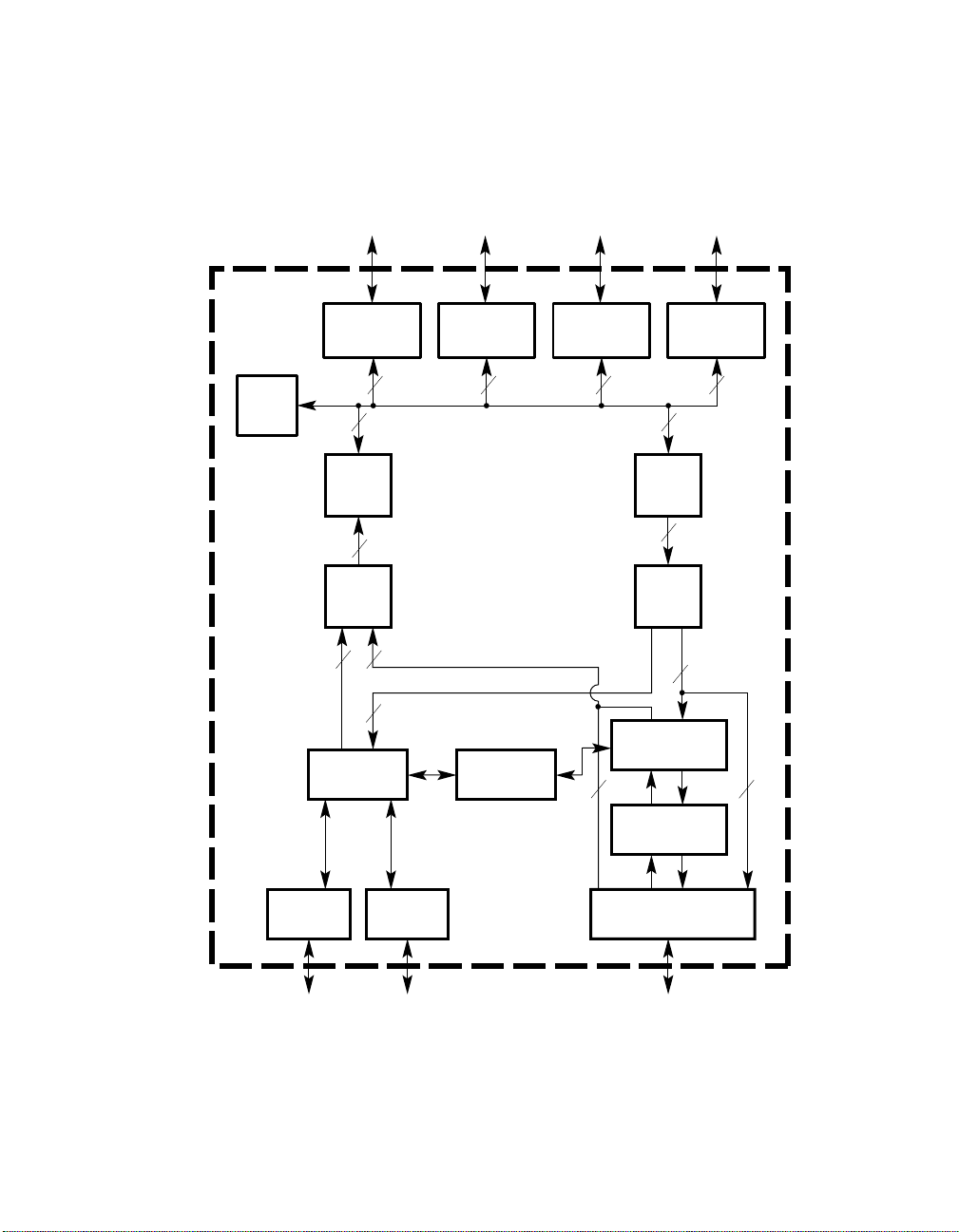
Figure 1–1 21143 Block Diagram
Microarchitecture
DMA
Boot ROM/
PCI/CardBus
PCI/CardBus
Interface
32
Rx
FIFO
16
RxM TxM
4
1
1
SIA Interface
External
Register
Boot
ROM
Port
NWAY
Serial
ROM
Serial
ROM
Port
4
Control
and LEDs
GeneralPurpose
Register
323232
32
Tx
FIFO
16
4
Physical Coding
Sublayer (PCS)
Board
4
4
AUI
Interface
10 Mb/s
10BASE-T
Interface
10 Mb/s
Scrambler/
Descrambler
MII/SYM Interface
10/100 Mb/s
LJ-04983.AI4
Introduction 1–5


This chapter describes the 21143 signals.
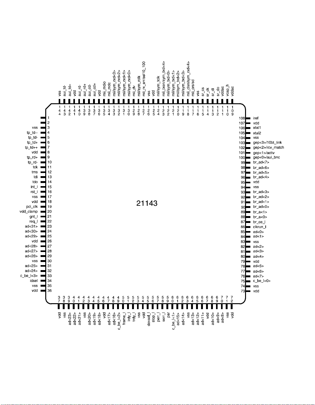
2.1 21143 Pinout
The 21143 is offered in two package styles: a 144-pin PQFP and a 144-pin TQFP.
Figure 2–1 shows the 21143 pinout used by both package types.
2
Signal Descriptions
Signal Descriptions 2–1
21143 Pinout
Figure 2–1 21143 Pinout Diagram (Top View)
vdd
vdd
2–2 Signal Descriptions
LJ-04940.WMF

2.2 Signal Descriptions
The following terms descri be the 21143 pinout used in Table 2–1:
• Address phase
Address and appropriate bus commands are driven during this cycle.
• Data phase
Data and the appropriate byte enable codes are driven during this cycle.
• _l
All pin names with the _l suffix are asserted low.
The following abbreviations are used in Table 2–1:
O = Output
I/O = Input/output
O/D = Open drain
P = Power
The following signals have an int erna l pull-up:
Signal Descriptions
tms
tdi
br_ce_l
sr_do
mii/sym_tclk
Signal sr_cs has an internal pull-down.
Signal Descriptions 2–3

Signal Descriptions
Table 2–1 provides a functional description of each of the 21143 signals. These
signals are listed al phabetically.
Table 2–1 Functional Descri ption of 21143 Signals
Pin
Signal Type
ad<31:0>
I/O See
Number Description
32-bit PCI address and dat a lines. Address and data bits are
Figure 2–1.
multiplexed on th e same p ins. Duri ng t he first cloc k cyc le of
a transaction, the address bits contain a physical address
(32 bits). During subs equent clock cycles, these same lines
contain 32 bits of data. A 21143 bus transaction cons ists of
an address phase followed by one or more data phases. The
21143 supports both read and write bursts (in master
operation only). Lit tle and big endian byte ordering can be
used.
aui_cd–
I 138 Attachment unit interface rec eive collision differential
negative data.
aui_cd+
I 137 Attachment unit interface rec eive collision differential
positive data.
aui_rd–
aui_rd+
aui_td–
I 140 Attachment unit interface receive differential negative data.
I 139 Attachment unit interface receive differential positive data.
O 143 Attachment unit interface transmit dif f erential negative
data.
aui_td+
O 142 Attachment unit in terface transmit differential positive data.
(Sheet 1 of 8)
br_a<0>
br_a<1>
br_ad<7:0>
br_ce_l
2–4 Signal Descriptions
O 88 Boot ROM addre ss line bit 0. In a 256KB configuration,
O 89 Boot ROM addre ss line bit 1. This pin also lat che s the boot
I/O See
O 87 Boot ROM or external register chip enable.
Figure 2–1.
this pin also carries in two consecutive addre s s cy cles, boot
ROM address bits 16 and 17.
ROM address and control lines by the two external latches.
Boot ROM address and data multiplexed lines bits 7
through 0. In two consecutive address cycles, these lines
contain the boot ROM addres s pins 7 through 2, oe_l and
we_l in the first cycle; and these lines contain boot ROM
address pins 15 through 8 in the second cycle. During the
data cycle, bits 7 through 0 contain data.

Signal Descriptions
Table 2–1 Functional Descri ption of 21143 Signals
Pin
Signal Type
c_be_l<3:0>
I/O See
Number Description
Bits 0 through 3 of the bus command and byte enable lines.
Figure 2–1.
Bus command and byte enable are multiplexed on the same
PCI pins.
During the address phase of the transaction, the se 4 bits
provide the bus command.
During the data phase, these 4 bits provide the byte ena ble.
The byte enable dete rmines which byte lines carry valid
data. For example, bit 0 applies to byte 0, and bit 3 applies
to byte 3.
clkrun_l
I/O
O/D
86 CardBus clock run indicates the clock status. The hos t
system asserts t his si gnal to indica te norm al op era tion of t he
clock. The host system deasserts clkrun_l when the cl ock i s
going to be slowed down to a nonoperational frequency.
The 21143 samples clkrun_l and whe n th e s ignal is foun d
deasserted, the 21143 asserts clkrun_l, requesting that
normal clock operation be maintained.
devsel_l
I/O 55 Device select is asserted by the target of the current bus
access. When the 21143 is the initiator of the current bus
access, it expects the target to assert devsel_l within 5 bus
cycles, confirming the access. If the target does not assert
devsel_l within the required bus cycles, the 21143 aborts
the cycle. To meet the timing requirements, the 21143
asserts this signal in a medium speed (within 2 bus cycle s).
(Sheet 2 of 8)
frame_l
gep<0>/aui_bnc
I/O 50 The frame_l signal is driven by the 21143 (bus master) to
indicate the beginning and duration of an ac cess. The
frame_l signal asserts to indicate the beginning of a bus
transa ction. Whi le frame_l is ass er t ed , d ata transf e r s
continue. The frame_l signal deasserts to indicate that the
next data phase is the final data phase transaction.
I/O 100 This pin can be configured by software to be:
• A general-purpose pin that performs either input or output
functions. It can provide an interrupt when it is an input
pin.
• A control pin that provides an AUI (10BASE5) or BNC
(10BASE2) select line.
This pin is mainly u sed to en ab le the ext er n al BN C
transceiver in 10BASE2 mode.
When set, the 10BASE5 mode is selected. When reset,
the 10BASE2 mode is selected .
Signal Descriptions 2–5

Signal Descriptions
Table 2–1 Functional Descri ption of 21143 Signals
Pin
Signal Type
gep<1>/activ
I/O 101 This pin can be configured by software to be:
Number Description
• A general-purpose pin that performs either input or output
functions. It can provide an interrupt when it is an input
pin
• A status pin that provide s an LED th at indicates either
receive or transmit activity
gep<2>/
rcv_match
I/O 102 This pin can be configured by software to be:
• A general-purpose pin that performs either input or output
functions.
• A status pin that provides an LED that indicates a receive
packet has passed address recognition.
gep<3>/10bt_link
I/O 103 This pin can be configured by software to be:
• A general-purpose pin that performs either input or output
functions.
• A status pin that provides an LED tha t indicates that the
10BASE-T link integrity te st has completed succes sfully
after the link was down.
gnt_l
I 21 Bus grant asserts to indicate to the 21143 tha t access to the
bus is granted.
idsel
I 34 Initialization device select asserts to indicate that the host is
issuing a configuration cycle to the 21143.
(Sheet 3 of 8)
int_l
iref
2–6 Signal Descriptions
O/D 15 Interrupt request asserts when one of the appropriate bits of
I 108 Current reference input for the ana log phase-locked loop
CSR5 sets and causes an interrupt, provid ed that the
corresponding mask bit in CSR7 is not asserted. Interrupt
request deasserts by writing a 1 into the appropriate CSR5
bit.
If more than one interrupt bit is asserted in CSR5 and the
host does not clear all input bits, the 21143 deasserts int_l
for one cycle to support edge-t riggered systems.
This pin must be pulled up by an exte rnal resistor.
logic.

Signal Descriptions
Table 2–1 Functional Descri ption of 21143 Signals
Pin
Signal Type
irdy_l
I/O 51 Initiator ready indi cate s th e bus mas ter ’s abilit y to com pl ete
Number Description
the current data phase of the transaction.
A data phase is completed on any rising edge of the clock
when both irdy_l and target ready trdy_l are asserted. Wait
cycles are inserted until both irdy_l and trdy_l are asserted
together.
When the 21143 is the bus master, irdy_l is asserted during
write operations to indicate that va lid data is present on the
32-bit ad lines. During read operations, the 21143 asserts
irdy_l to indicate th at it is re a dy to acc ep t data.
mii_clsn/
sym_rxd<4>
I 118 In MII mode (CSR6<18>=1, CSR6<23>=0), this pin
functions as the colli sion de tect. When t he exte rnal phys ica l
layer protocol (PHY) device detects a collision, it asserts
this pin.
In SYM mode (CSR6<18>=1, CSR6<23>=1), this pin
functions as receive data. This line along with the four
rece iv e li n es (sym_rxd< 4:0>) provides five parallel data
lines in symbol form. This data is controlled by an ext ernal
physical layer medi um-dependent (PMD) dev ice and should
be synchronized to the sym_rclk signal.
mii_crs/sd
I 117 In MII mode this pin functions as the carrie r se ns e an d is
asserted by the PHY when the media is active.
In SYM mode this pin functions as the signal detect
indication. It is controlled by an external P MD device.
(Sheet 4 of 8)
mii_dv
mii_mdc
mii_mdio
mii/sym_rclk
I 129 Data valid is as serted by an external P HY when re ceive data
is present on the mii_rxd li nes and is deasserte d at the end
of the packet. This signal should be synchronized with the
mii_rclk signal.
O 134 MII management data clock is sourced by the 21143 to the
PHY devices as a timing reference for the transfer of
information on the mii_mdio signal.
I/O 135 MII management data input/output tra nsfers control
information and status between the PHY and the 21143.
I 128 Supports either the 25-MHz or 2.5- MHz recei ve cloc k. This
clock is recovered by the PHY.
Signal Descriptions 2–7

Signal Descriptions
Table 2–1 Functional Descri ption of 21143 Signals
Pin
Signal Type
mii_rx_err/
sel10_100
I/O 127 In MII mode (CSR6<18>=1, CSR6<23>=0), this pin
Number Description
functions as receive error. It is asserted when a data
decoding error is detected by an external PHY device. Thi s
signal is synchronized to mii_rclk and can be asserted for a
minimum of one receive cloc k. When ass erted during a
packet reception, i t sets the cyclic redundancy check (CRC)
error bit in the receive descriptor (RDES0).
In SYM mode (CSR6<23>=1), this pin functions as select
10/100. The signal sel10_100 equals 1 when the 21143 is in
100-Mb/s SYM mode (CSR6<18>=1) and equals 0 when
the 21143 is in 10BASE-T/AUI mode (CS R6<18>=0).
mii/sym_rxd<3 :0>
ISee
Figure 2–1.
Four parallel r eceive data lines. This data is driven by an
external PHY that attached the media and should be
synchronized with the mii_rclk signal.
mii/sym_tclk
I 124 Supports the 25-MHz or 2.5-MHz transmit clock supplied
by the external PMD device . This clock should always be
active.
mii/sym_txd<3:0>
OSee
Figure 2–1.
Four parallel transmit data lines. This data is synchronized
to the assertion of the mi i_t clk signal and is latched by the
external PHY on the rising edge of the mii_tclk signal.
(Sheet 5 of 8)
mii_txen/
sym_txd<4>
par
pci_clk
2–8 Signal Descriptions
O 123 In MII mode, this pin functions as transmit enable. It
I/O 59 Parity is calculate d by th e 21 143 as an ev en pari ty b it for t he
I 19 The clock provides the timing for the 21143 rel ated PCI bus
indicates th a t a tr an s missio n is ac ti v e on the MII po r t to an
external PHY device.
In SYM mode, this pin functions as transmit data. This line
along with the four data transmit lines (sym_txd<3:0>)
provides five parallel data lines in symbol form. The da ta is
synchronized to the rising edge of the sym_tclk signal.
32-bit ad and 4-bit c_be_l lines.
During address and data pha se s, parity is calculated on all
the ad and c_be_l lines whet her or not any of these lines
carry meaningful info rmation.
transactions. All the bus signals are sampled on the rising
edge of pci_clk. The clock fre quency range is between
20 MHz and 33 MHz.
 Loading...