

Digital Equipment 14BM18 Service Manual

FILE NO. SM-CTV-O-158
COLOR TELEVISION
SERVICE MANUAL
MODEL NO. 14BM18
CHASSIS NO. EX-1A3
Please read this manual carefully before service

TABLE OF CONTENTS
SPECIFICATIONS··················································································································1
SAFETY INSTRUCTIONS AND MAINTENANCE········································2
X-RAY RADIATION PRECAUTION ···································································································2
SAFETY PRECAUTION ····················································································································
2
PRODUCT SAFETY NOTICE ···········································································································
3
SAFETY SYMBOL DESCRIPTION ···································································································
3
MAINTENANCE·································································································································
4
ADJUSTMENTS
······················································································································
5
SET-UP ADJUSTMENTS ··················································································································5
CIRCUIT ADJUSTMENTS·················································································································
8
STRUCTURE AND CHASSIS FUNCTION DESCRIPTION
···············
15
STRUCTURE BLOCK DIAGRAM··································································································· 15
BLOCK DIAGRAM FOR SUPPLY VOLTAGE SYSTEM·································································
16
CHASSIS DESCRIPTION···············································································································
17
SERVICE DATA···················································································································· 18
TECHNICAL DATA OF KEY ICS ···································································································· 18
WAVEFORMS OF KEY POINTS ····································································································
31
SERVICE DATA OF KEY ICS·········································································································
33
REPLACEMENT OF PARTS ··········································································································
36
APPENDIX
1. CIRCUIT DIAGRAM
2. PRINTED CIRCUIT BOARD DIAGRAMS
3. FINAL WIRING DIAGRAM
4. FINAL ASSEMBLY DIAGRAM
SERVICE MANUAL
1
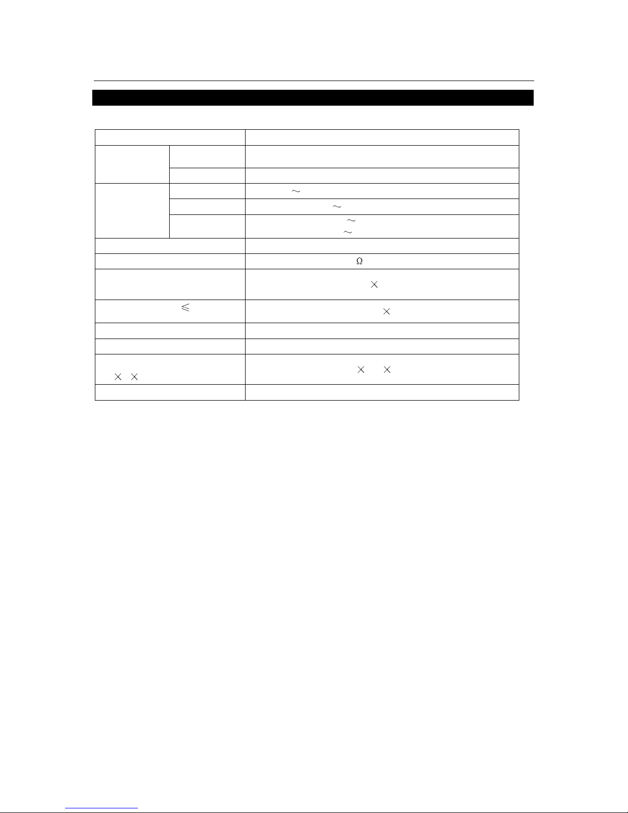
SPECIFICATIONS
Model Number 14BM18
Color system
PAL4.43, NTSC3.58, NTSC4.43, SECAM
RF system
Sound system B/G, I, M, D/K
VHF
C1
C12 (49.75-85.25MHz, 168.25-216.25MHz)
UHF
C13
C57 (471.25-863.25MHz)
Receiving
channel
CATV
Z1
Z7 (111-167MHz)
Z8
Z35 (223-447MHz)
Programs preset 236(0-235)
Antenna input
75
(unbalanced)
Picture tube (Approx.)
Effective screen dimensions
280
210mm
Audio output (THD 7%)
2W
2
Power source 110-240V ~, 50/60Hz
Weight (Approx.) 10.5kg
Dimensions
(W
H D) (Approx.)
416
332 390mm
Rated power consumption 69W
Note: Designs and specifications are subject to change without notice.

SERVICE MANUAL
2
INSTRUCTIONS FOR SERVICE SAFETY AND MAINTENANCE
WARNING: BEFORE SERVICING THIS CHASSIS, READ THE X-RA Y RADIATION PRECAUTION ,
SAFETY PRECAUTION AND PRODUCT SAFETY NOTICE INSTRUCTION BELOW.
X-RAY RADIATION PRECAUTION
1. The EHT must be checked every time the TV is serviced to ensure that the CRT does not emit
X-ray radiation as result of excessive EHT voltage. The maximum EHT voltage permissible in any
operating circumstances must not exceed the rated value. When checking the EHT, use the High
Voltage Check procedure in this manual using an accurate EHT voltmeter.
2. The only source of X-RAY radiation in this TV is the CRT. The TV minimizes X-RAY radiation, which
ensures safety during normal operation. To prevent X-ray radiation, the replacement CRT must be
identical to the original fitted as specified in the parts list.
3. Some components used in this TV have safety related characteristics preventing the CRT from
emitting X-ray radiation. For continued safety, replacement component should be made after
referring the PRODUCT SAFETY NOTICE below.
4. Service and adjustment of the TV may result in changes in the nominal EHT voltage of the CRT
anode. So ensure that the maximum EHT voltage does not exceed the rated value after service
and adjustment.
SAFETY PRECAUTION
WARNING: REFER SERVICING TO QUALIFIED SERVICE PERSONNEL ONLY.
1. The TV has a nominal working EHT voltage. Extreme caution should be exercised when working
on the TV with the back removed.
1.1 Do not attempt to service this TV if you are not conversant with the precautions and procedures for
working on high voltage equipment.
1.2 When handling or working on the CRT, always discharge the anode to the TV chassis before
removing the anode cap in case of electric shock.
1.3 The CRT, if broken, will violently expel glass fragments. Use shatterproof goggles and take extreme
care while handling.
1.4 Do not hold the CRT by the neck as this is a very dangerous practice.
2. It is essential that to maintain the safety of the customer all power cord forms be replaced exactly
as supplied from factory.
3. Voltage exists between the hot and cold ground when the TV is in operation. Install a suitable
isolating transformer of beyond rated overall power when servicing or connecting any test
equipment for the sake of safety.
4. When replacing ICs, use specific tools or a static-proof electric iron with small power (below 35W).

SERVICE MANUAL
3
5. Do not use a magnetized screwdriver when tightening or loosing the deflection yoke assembly to
avoid electronic gun magnetized and decrement in convergence of the CRT.
6. When remounting the TV chassis, ensure that all guard devices, such as nonmetal control buttons,
switch, insulating sleeve, shielding cover, isolating resistors and capacitors, are installed on the
original place.
7. Replace blown fuses within the TV with the fuse specified in the parts list.
8. When replacing wires or components to terminals or tags, wind the leads around the terminal
before soldering. When replacing safety components identified by the international hazard symbols
on the circuit diagram and parts list, it must be the company-approved type and must be mounted
as the original.
9. Keep wires away from high temperature components.
PRODUCT SAFETY NOTICE
CAUTION: FOR YOU PROTECTION, THE FOLLOWING PRODUCT SAFETY NOTICE SHOULD BE
READ CAREFULLY BEFORE OPERATING AND SERVICING THIS TV SET.
1. Many electrical and mechanical components in this chassis have special safety-related
characteristics. These characteristics are often passed unnoticed by a visual inspection and the
X-ray radiation protection afforded by them cannot necessarily be obtained by using replacements
rated at higher voltages or wattage, etc. Components which have these special safety
characteristics in this manual and its supplements are identified by the international hazard
symbols on the circuit diagram and parts list. Before replacing any of these components read the
parts list in this manual carefully. Substitute replacement components which do not have the same
safety characteristics as specified in the parts list may create X-ray radiation.
2. Do not slap or beat the cabinet or CRT, since this may result in fire or explosion.
3. Never allow the TV sharing a plug or socket with other large-power equipment. Doing so may result
in too large load, causing fire.
4. Do not allow anything to rest on or roll over the power cord. Protect the power cord from being
walked on, modified, cut or pinched, particularly at plugs.
5. Do not place any objects, especially heavy objects and lightings, on top of the TV set. Do not install
the TV near any heat sources such as radiators, heat registers, stove, or other apparatus that
produce heat.
6. Service personnel should observe the SAFETY INSTRUCTIONS in this manual during use and
servicing of this TV set. Otherwise, the resulted damage is not protected by the manufacturer.
SAFETY SYMBOL DESCRIPTION
The lightning symbol in the triangle tells you that the voltage inside this product may be
strong enough to cause an electric shock. Extreme caution should be exercised when

SERVICE MANUAL
4
working on the TV with the back removed.
This is an international hazard symbol, telling you that the components identified by the
symbol have special safety-related characteristics.
FDA
This symbol tells you that the critical components identified by the FDA marking have
special safety-related characteristics.
UL
This symbol tells you that the critical components identified by the UL marking have
special safety-related characteristics.
C UL
This symbol tells you that the critical components identified by the C-UL marking have
been evaluated to the UL and C-UL standards and have special safety-related
characteristics.
VDE
This symbol tells you that the critical components identified by the VDE marking have
special safety-related characteristics.
MAINTENANCE
1. Install the TV set on a stable and level surface. Do not place the set near or over a radiator or heat
register, or where it is exposed to direct sunlight.
2. Do not install the TV set in a place exposed to rain, water, excessive dust, mechanical vibrations or
impacts.
3. Allow enough space (at least 10cm) between the TV and wall or enclosures for proper ventilation.
4. Slots and openings in the cabinet should never be blocked by clothes or other objects.
5. Please power off the TV set and disconnect it from the wall immediately if any abnormal condition
are met, such as bad smell, belching smoke, sparkling, abnormal sound, no picture/sound/raster.
Hold the plug firmly when disconnecting the power cord.
6. Unplug the TV set from the wall outlet before cleaning or polishing it. Use a dry soft cloth for
cleaning the exterior of the TV set or CRT screen. Do not use liquid cleaners or aerosol cleaners.

SERVICE MANUAL
5
ADJUSTMENTS
SET-UP ADJUSTMENTS
The following adjustments should be made when a complete realignment is required or a new picture
tube is installed.
Perform the adjustments in the following order:
1. Color purity
2. Convergence
3. White balance
Notes:
The purity/convergence magnet assembly and rubber wedges need mechanical positioning.
For some picture tubes, purity/ convergence adjustments are not required.
1. Color Purity Adjustment
Preparation:
Before starting this adjustment, adjust the vertical sync, horizontal sync, vertical amplitude and
focus.
1.1 Face the TV set north or south.
1.2 Connect the power plug into the wall outlet and turn on the main power switch of the TV set.
1.3 Operate the TV for at least 15 minutes.
1.4 Degauss the TV set using a specific degaussing coil.
1.5 Set the brightness and contrast to maximum.
1.6 Counter clockwise rotate the R/B low brightness potentiometers to the end and rotate the green low
brightness potentiometer to center.
1.7 Receive green raster pattern signals.
1.8 Loosen the clamp screw holding the deflection yoke assembly and slide it forward or backward to
display a vertical green zone on the screen. Rotate and spread the tabs of the purity magnet
around the neck of the CRT until the green zone is located vertically at the center of the screen.
1.9 Slowly move the deflection yoke assembly forward or backward until a uniform green screen is
obtained.
1.10 Tighten the clamp screw of the assembly temporarily. Check purity of the red raster and blue raster
until purities of the three rasters meet the requirement.
SERVICE MANUAL
6
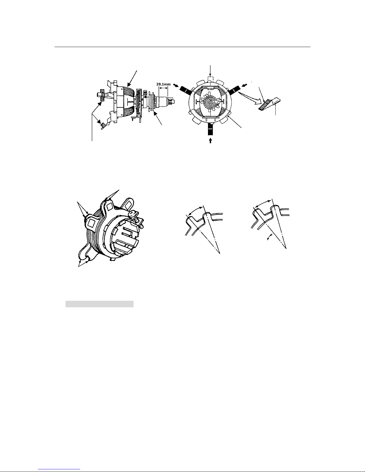
Fig. 1
2. Convergence Adjustment
Preparation:
Before attempting any convergence adjustment, the TV should be operated for at least 15 minutes.
2.1 Center convergence adjustment
2.1.1 Receive dot pattern.
2.1.2 Adjust the brightness/contrast controls to obtain a sharp picture.
2.1.3 Adjust two tabs of the 4-pole magnet to change the angle between them and red and blue
vertical lines are superimposed each other on the center of the screen.
2.1.4 Turn both tabs at the same time keeping the angle constant to superimpose red and blue
horizontal on the center of the screen.
2.1.5 Adjust two tabs of the 6-pole magnet to superimpose red/blue line and green line.
2.1.6 Remember red and blue movement. Repeat steps2.1.3-2..1.5 until optimal convergence is
Deflection Coil
Dummy Wedge
Rubber Wedge
Adhesive
Deflection Yoke
Purity/Convergence
Ma
g
net Module
Glass Cloth Tapes
6-pole Magnet
Adj
ust the Angle (Vertical Lines
)
Fixed
Rotate Two Tabs At the
Same Time
(
Horizontal Lines
)
Adjustment of Magnets
Purity Magnet
Conver
g
ence Magnet Assembl
y
4-pole Magnet
Fig. 2
SERVICE MANUAL
7
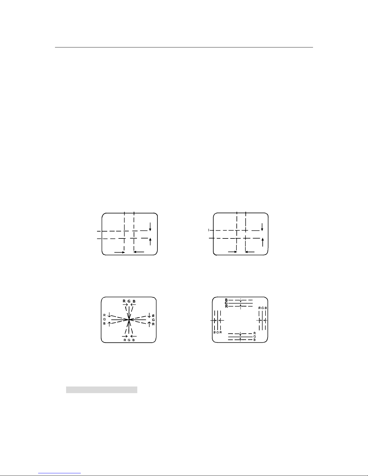
Incline the Yoke up (or down) Incline the Yoke Right(or left)
Circumference Convergence by DEF Yoke
Fig. 3
obtained.
2.2 Circumference convergence adjustment
2.2.1 Loosen the clamp screw holding the deflection yoke assembly and allow it tilting.
2.2.2 Temporarily put the first wedge between the picture tube and deflection yoke assembly. Move
front of the deflection yoke up or down to obtain better convergence in circumference. Push the
mounted wedge in to fix the yoke temporarily.
2.2.3 Put the second wedge into bottom.
2.2.4 Move front of the deflection yoke to the left or right to obtain better convergence in
circumference.
2.2.5 Fix the deflection yoke position and put the third wedge in either upper space. Fasten the
deflection yoke assembly on the picture tube.
2.2.6 Detach the temporarily mounted wedge and put it in either upper space. Fasten the deflection
yoke assembly on the picture tube.
2.2.7 After fastening the three wedges, recheck overall convergence and ensure to get optimal
convergence. Tighten the lamp screw holding the deflection yoke assembly.
3. White Balance Adjustment
Generally, white balance adjustment is made with professional equipment. It’s not practical to get
good white balance only through manual adjustment. For TVs with I
2
C bus control, change the bus
data to adjust white balance.
BLU Red Red/BLU
BLU
Red
4-pole Magnet Movement 6-pole Magnet
Movement
Red/BL
U

SERVICE MANUAL
8
CIRCUIT ADJUSTMENTS
Preparation:
Circuit adjustments should be made only after completion of set-up adjustments.
Circuit adjustments can be performed using the adjustable components inside the TV set. For TVs with
I
2
C bus control, first change the bus data.
1. Degaussing
A degaussing coil is built inside he TV set. Each time the TV is powered on, the degaussing coil will
automatically degauss the TV. If the TV is magnetized by external strong magnetic field, causing
color spot on the screen, use a specific degausser to demagnetize the TV in the following ways.
Otherwise, color distortion will be shown on the screen.
1.1 Power on the TV set and operate it for at least 15 minutes.
1.2 Receive red full-field pattern.
1.3 Power on the specific degausser and face it to the TV screen.
1.4 Turn on the degausser. Slowly move it around the screen and slowly take it away from the TV.
1.5 Repeat the above steps until the TV is degaussed completely.
2. Supply Voltage Adjustment
Caution: +B voltage has close relation to high voltage. To prevent X-ray radiation, set +B voltage to
the rated voltage.
2.1 Make sure that the supply voltage is within the range of the rated value.
2.2 Connect a digital voltmeter to the +B voltage output terminal of the TV set. Power on the TV and set
the brightness and sub-brightness to minimum.
2.3 Regulate voltage adjustment components on the power PCB to make the voltmeter read 115±1V.
3. High Voltage Inspection
Caution: No high voltage adjustment components inside the chassis. Please perform high voltage
inspection in the following ways.
3.1 Connect a precise static high voltmeter to the second anode (inside the high voltage cap) of the
picture tube.
3.2 Plug in the supply socket (110-240V, AC, 50/60Hz) and turn on the TV. Set the brightness and
contrast to minimum (0
A).
3.3 The high voltage reading should be less than the EHT limitation.
3.4 Change the brightness from minimum to maximum, and ensure high voltage not beyond the
limitation in any case.
Nominal EHT voltage: 22
1.3KV Limited EHT voltage: 25KV
4. Focus Adjustment
Caution: Dangerously high voltages are present inside the TV. Extreme caution should be
exercised when working on the TV with the back removed.
4.1 After removing the back cover, look for the FBT on the main PCB. There should be a FCB on the
SERVICE MANUAL
9
S
VS 0-3F 25
xxxxxxxx
FBT.
4.2 Power on the TV and preheat it for 15 min.
4.3 Receive a normal TV signal. Rotate knob of the FCB until you get a sharp picture.
5. Safety Inspection
5.1 Inspection for insulation and voltage-resistant
Perform safety test for all naked metal of the TV. Supply high voltage of 3000V AC, 50Hz (limit
current of 10mA) between all naked metal and cold ground. Test every point for 3 min. and ensure
no arcing and sparking.
5.2 Requirements for insulation resistance
Measure resistance between naked metal of the TV and feed end of the power cord to be infinity
with a DC-500 high resistance meter and insulation resistance between the naked metal and
degaussing coil to be over 20M
.
6. DESIGN/SERVICE mode
6.1 To enter the USER SERVICE mode
Caution: The user service mode adjustment can be changed only when service personnel adjust
the whole set data during servicing. As the control data have dramatic effects on functions and
performance of the TV, service personnel should not tell user how to
enter the SERVICE mode to avoid improper data settings.
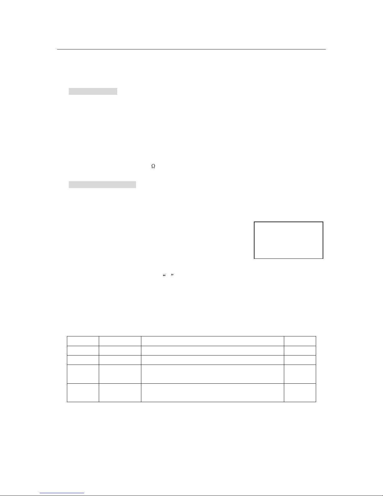
6.1.1 Set the volume to 0. Then press and hold the MUTE button on
the remote control, and press the MENU button on the TV to
enter the SERVICE mode. (In this case, the S mode cannot be
stored in the EEPROM. To exit from the S mode, turn off the TV set. )
6.1.2 After entering the S mode, Red
S is displayed on the upper center of the screen and MENU1
is default. Use the POS+/- buttons to highlight an adjustment and the VOL+/- buttons to adjust
it. The adjusted data are immediately output and stored in the EEPROM
6.2 Bus data in the S mode
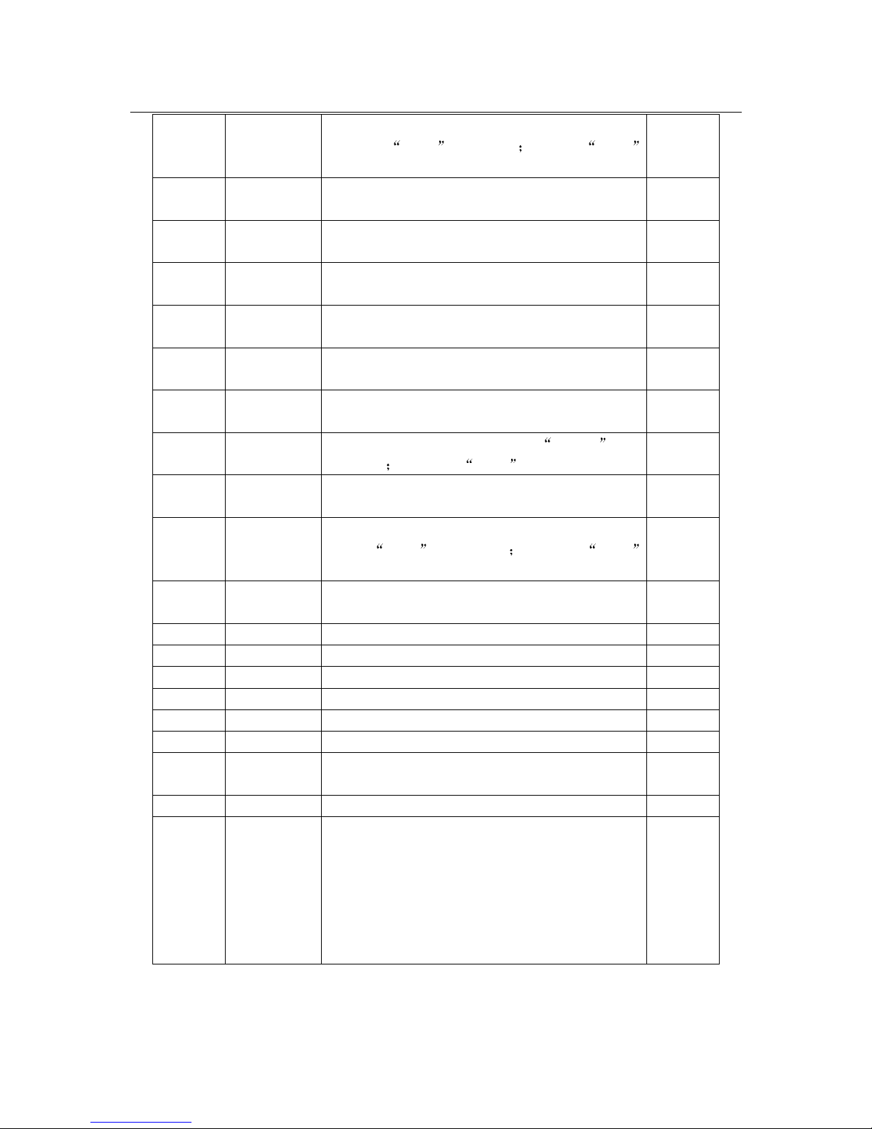
Table 1 Adjustment and Option Data in S mode
Item Adjustment Description Remarks
CORE 03 Coring (for some CPU only)
0-IF 20 Sound adjustment setting (for some CPU only)
5PAR/6P
AR
1F Parallelogram correction (for large-screen only)
5BOW/6
BOW
1F Curve correction (for large-screen only)
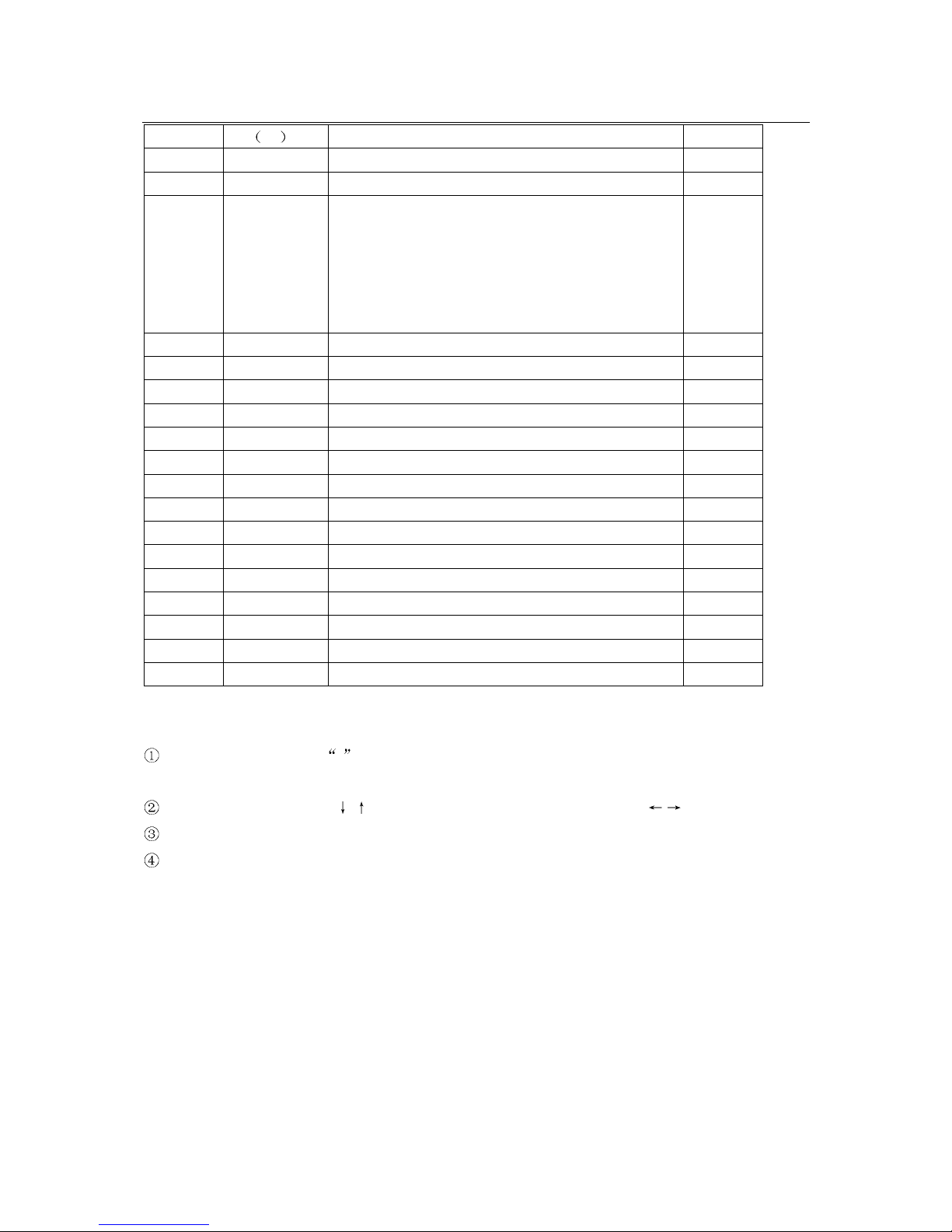
(continued)
SERVICE MANUAL
10
5HSH/6H
SH
Set to the
optimal mode
Horizontal center in the TV mode for 50Hz/60Hz
For 50Hz,
5HSH is displayed for 60Hz, 6HSH
is displayed.
*
5EWW/6
EWW
1F East-West correction (for large-screen only)
5EWP/6
EWP
1F
East-West parabola correction (for large-screen
only)
5UCR/6
UCR
1F
Upper corner parabola correction (for large-screen
only)
5LCR/6L
CR
1F
Lower corner parabola correction (for large-screen
only)
5EWT/6
EWT
1F Trapezoidal correction (for large-screen only)
5VSL/6V
SL
1F Vertical slope (for large-screen only) *
5VAM/6V
AM
1F
Vertical amplitude; For 50Hz,
5VAM is
displayed
for 60Hz, 6VAM is displayed.
*
5SCL/6S
CL
Set to the
optimal mode
S correction *
5VSH/6V
SH
Set to the
optimal mode
Vertical center in the TV mode for 50Hz/60Hz. For
50Hz,
5VSH is displayed for 60Hz, 6VSH
is displayed.
*
5VOF/6V
OF
Set to the
optimal mode
OSD vertical center *
VX 19 Vertical zoom (for large-screen only)
RED 20 Red gun cutoff voltage *
GRN 20 Green gun cutoff voltage *
WPR 1F Red gun drive voltage *
WPG 1F Green gun drive voltage *
WPB 1F Blue gun drive voltage *
YDFP/Y
DFN
07
PAL brightness delay time/ NTSC brightness delay
time
TOP 10-1F UOC AGC *
VOL 26
TV audio output power can be adjusted by means of
UOC audio output amplitude. Generally, UOC audio
output amplitude is set to 26 for 21” models with
stereo output of 3W+3W; 2C for 21” models with
stereo output of 5W+5W; 24 for 14” models with
mono output of 2WX2; 22 for 14” models with mono
output of 1WX2.
***
(continued)
SERVICE MANUAL
11
IFFS
03
02
PIF (02-38.9MHz, 03-38MHz)
HDOL 00-07 Cathode drive level (typical: 04-07)
AGC 03 IF ACG speed
VG2B 3A
VG2 brightness setting(VG2B): 3A for 21” models;
2E for 14” models;
Contrast Max. setting (MCON): 30 for 21” Malaysia
Matsushita or BMCC CRT with ferrite mask;
MCON: 30; VG2B: 30, HDOL: 04 for 21” Chunghwa
CRT
SBRI 1F Sub brightness
MBRI 30 Brightness Max.
SCON 20 Sub contrast
MCON 39 Contrast Max.
SCOL 32 Sub color
OP1 87 Option set byte 1 ***
OP2 01 Option set byte 2 ***
OP3 FF Option set byte 3 ***
OP4 F6 Option set byte 4 ***
OP5 76 Option set byte 5 ***
OP6 1C Option set byte 6 ***
INIT EEPROM initialization
VG2 Adjusting screen voltage with VG2 *
VSD Vertical output off
STS0/1/2 System status byte
Notes:
The data marked with
* have been adjusted in the MANUFACTURE mode. Take care when in
service and adjustment.
To write in logo, use the
/ buttons to highlight an adjustment and the / buttons to adjust.
The data sheet may differ dependent on different models.
The data sheet may differ dependent on different CRTs for the same model.
6.3 Option set
With remote control system software TDA935X, all options can be set in the SERVICE mode and
stored in EEPROM. Data related to picture, sound and geometric adjustment are also stored in
EEPROM.
 Loading...