

Digital Equipment VAX 4000 Series, 105A, 106A, 100, 100A Installation Information

RackmountVAX4000
Model100/100A/105A/106A
InstallationInformation
Order Number: EK–465RA–IN. D01
Digital Equipment Corporation
Maynard, Massachusetts

June 1995
The information in this document is subject to change without notice and should not be
construed as a commitment by Digital Equipment Corporation. Digital Equipment Corporation
assumes no responsibility for any errors that may appear in this document.
Restricted Rights: Use, duplication, or disclosure by the U.S. Government is subject to
restrictions set forth in subparagraph (c)(1)(ii) of the Rights in Technical Data and Computer
Software Clause at DFARS 252.227-7013.
FCC NOTICE: This equipment has been tested and found to comply with the limits for a
Class A digital device, pursuant to Part 15 of the FCC Rules. These limits are designed to
provide reasonable protection against harmful interference when the equipment is operated in
a commercial environment. This equipment generates, uses, and can radiate radio frequency
energy and, if not installed and used in accordance with the instruction manual, may cause
harmful interference to radio communications.
Any changes or modifications made to this equipment may void the user’s authority to operate
this equipment.
Operation of this equipment in a residential area may cause interference in which case the user
at his own expense will be required to take whatever measures may be required to correct the
interference.
© Digital Equipment Corporation 1994, 1995. All Rights Reserved.
Printed in U.S.A.
The postpaid Reader’s Comments form at the end of this document requests your critical
evaluation to assist in preparing future documentation.
The following are trademarks of Digital Equipment Corporation: DEC, Digital, MicroVAX,
Q–bus, ThinWire, VAX, VAX DOCUMENT, VMS, VT, and the DIGITAL logo.
All other trademarks and registered trademarks are the property of their respective owners.
S2884
This document was prepared using VAX DOCUMENT Version 2.1.

EC:
Warning! This is a Class A product. In a domestic environment this product may cause radio
interference in which case the user may be required to take adequate measures.
Achtung! Dieses ist ein Gerät der Funkstörgrenzwerklasse A. In Wohnbereichen können
bei Betrieb dieses Gerätes Rundfunkstörungen auftreten, in welchen Fällen der Benutzer für
entsprechende Gegenmaßnahmen verantwortlich ist.
Attention! Ceci est un produit de Classe A. Dans un environnement domestique, ce produit
risque de créer des interférences radioeléctriques, il appartiendra alors à l’utilisateur de prendre
les mesures spécifiques appropriées.
ACOUSTICS: Preliminary declared values per ISO 9296 and ISO 7779/DIN EN27779:
Sound Power Level
,B
L
wAd
Sound Pressure Level
, dBA (Bystander Positions)
L
pAm
Idle 4.9 33
Operating 4.9 33
Current values for specific configurations are available from Digital representatives. 1 B = 10
dBA.
SCHALLEMISSIONSWERTE: Verläufige Werteangaben nach ISO 9296 und ISO 7779/DIN
EN27779:
Schalleistungspegel
L
,B
wAd
Schalldruckpegel
L
, dBA (Zuschauerpositionen)
pAm
Leerlauf 4,9 33
Betrieb 4,9 33
Aktuelle Werte für spezielle Ausrüstungsstufen sind über die Digital Equipment Vertretungen
erhältlich. 1 B = 10 dBA.


Contents
Preface ..................................................... xi
1 Installation Procedure
1.1 Introduction ......................................... 1–1
1.2 Installation Procedure ................................. 1–2
2 Operator Access and Control Procedure
3 Troubleshooting and Diagnostics
4 Maintenance and FRU Replacement Procedures
4.1 Accessing the RM 4000-10xx . ........................... 4–2
4.2 Removing and Installing the Shipping Strap and Bracket ...... 4–2
4.3 Removing the Rackmount Enclosure Cover (P/N 70-30948-01). . 4–6
4.4 Removing and Replacing the Internal Q–bus Cables
(P/N 17-03545-01) . ................................... 4–11
4.5 Removing and Replacing the DSSI Bus 0 Cable
(P/N 17-03544-01 or 17-04189-01) ........................ 4–12
4.6 Removing and Replacing the DSSI Bus 1 Cable
(P/N 17-03778-01) . ................................... 4–13
4.7 Removing and Replacing the Internal SCSI Cable
(P/N 17-02944-01 or 17-02542-01) ........................ 4–18
4.8 Removing and Replacing the DSSI Card ................... 4–19
4.9 Removing and Replacing the CPU Module .................. 4–26
v

A Shelf Assembly
B Connecting Peripheral Device Cables
B.1 Connecting a Peripheral Cable to MMJ Port 0 and 1 . . . ....... B–2
B.2 Connecting a Peripheral Cable to Asynchronous Port A ....... B–3
B.3 Connecting a Peripheral Cable to Asynchronous Port A
(DHW42-CA) ........................................ B–4
B.4 Connecting a Peripheral Cable to Synchronous Port 0 and 1, and
to the Modem Port .................................... B–5
B.5 Connecting a Peripheral Cable to the Asynchronous Modem
Control Port . ........................................ B–6
B.6 Connecting Cables to SCSI Cable Ports .................... B–7
B.7 Connecting External DSSI Bus Cables to Internal DSSI Bus
Cable Ports . ........................................ B–8
B.8 Connecting Cables to Top Cover Cable Ports ................ B–9
B.8.1 Connecting Q–bus Cable Ports ........................ B–9
B.8.2 Connecting External Bus DSSI Cables to External Bus DSSI
Cable Ports ...................................... B–10
C Single to Dual DSSI Upgrade Procedure
D Hardware Specifications
D.1 System Unit Specifications .............................. D–2
D.2 Internal DSSI Device Specifications ....................... D–5
E Upgrade and Return Forms
Examples
1–1 Successful Power-Up Test Screen ...................... 1–45
1–2 Unsuccessful Power-Up Test Screen .................... 1–46
vi

Figures
1–1 RM 4000-10xx System Kit Contents ................... 1–4
1–2 RM 4000-10xx Shelf Kit Contents (P/N 70-30949-01) ...... 1–6
1–3 2T-RAK41-AA/AB/AC Kit Contents (For Desktop to
Rackmount System Conversion) ....................... 1–10
1–4 2T-KFDDA-DF Desktop to Rackmount / Single to Dual DSSI
Field Installable Upgrade Kit Contents ................. 1–12
1–5 2T-KFDDA-AF Single to Dual DSSI Field Installable
Upgrade Kit Contents . . . ........................... 1–14
1–6 Removing the Desktop Enclosure Cover................. 1–16
1–7 Removing the Bustle Frame from the Enclosure .......... 1–18
1–8 VAX 4000-10xx Port Cover ........................... 1–19
1–9 Installing DSSI Plate Assembly....................... 1–21
1–10 Attaching the Internal Q–bus Cables to Rackmount Top
Cover Bustle . . ................................... 1–22
1–11 Disconnecting the Internal Power Cables................ 1–23
1–12 Disconnecting Internal DSSI Connectors ................ 1–24
1–13 Disconnecting the Internal SCSI Cable ................. 1–25
1–14 Removing the Single DSSI Card . . . ................... 1–26
1–15 Installing the Dual DSSI Card ........................ 1–28
1–16 Installing New Rackmount Top Cover .................. 1–30
1–17 Placing the VAX 4000-10xx Medallion .................. 1–31
1–18 Front and Rear Mounting Brackets . ................... 1–33
1–19 Installing the Shelf in the Cabinet . . ................... 1–34
1–20 RETMA Spacing ................................... 1–35
1–21 Installing the VAX 4000-10xx System on the Shelf ........ 1–37
1–22 Installing the Cable Management Bracket ............... 1–39
1–23 Making Console Connections ......................... 1–41
1–24 Installing the Cable Barrier on the Shelf ................ 1–43
1–25 Installing the Front Bezel ........................... 1–48
2–1 Front Bezel . . . ................................... 2–2
4–1 Removing and Installing the Shipping Bracket . .......... 4–3
4–2 Removing the Shipping Strap ........................ 4–5
4–3 Removing the Rackmount Enclosure Cover .............. 4–7
4–4 Removing and Installing the Two DSSI External Bus
Connectors ....................................... 4–9
4–5 Internal Connectors ................................ 4–10
vii

4–6 Removing Internal Q–bus Connectors . . ................ 4–11
4–7 Removing the Internal DSSI Bus 0 Cable Connectors from
Rear Bulkhead .................................... 4–12
4–8 Disconnecting the Internal Power Cables................ 4–14
4–9 Disconnecting Internal DSSI Connectors ................ 4–15
4–10 Disconnecting the Internal SCSI Cable . ................ 4–16
4–11 Disconnecting DSSI Cable from DSSI Card .............. 4–17
4–12 Removing the Internal SCSI Cable .................... 4–18
4–13 Disconnecting the Internal Power Cables................ 4–20
4–14 Disconnecting Internal DSSI Connectors ................ 4–21
4–15 Disconnecting the Internal SCSI Cable . ................ 4–22
4–16 Removing the Dual DSSI Card ....................... 4–23
4–17 Installing the Dual DSSI Card ........................ 4–25
4–18 Removing a SIMM . ................................ 4–27
4–19 Removing the CPU Module . . ........................ 4–29
A–1 Attaching Slides to the Shelf . ........................ A–2
A–2 Assembling the Shelf ............................... A–3
B–1 Connecting a Peripheral Cable to MMJ Port 0 and 1....... B–2
B–2 Connecting a Peripheral Cable to Asynchronous Port A .... B–3
B–3 Connecting a Peripheral Cable to Asynchronous Port A
(DHW42-CA) ..................................... B–4
B–4 Connecting a Peripheral Cable to Synchronous Port 0 and 1,
and to the Modem Port ............................. B–5
B–5 SCSI Cable Ports . . ................................ B–7
B–6 DSSI Cable Ports . . ................................ B–8
B–7 Q–bus Cable Ports . ................................ B–9
B–8 DSSI Cable Ports . . ................................ B–10
C–1 2T-KFDDA-CF Single-to-Dual DSSI Field Installable
Upgrade Kit Contents .............................. C–2
C–2 2T-KFDDA-AF Single-to-Dual DSSI Field Installable
Upgrade Kit Contents .............................. C–4
C–3 Disconnecting the Internal Power Cables................ C–6
C–4 Disconnecting Internal DSSI Connectors ................ C–7
C–5 Disconnecting the Internal SCSI Cable . ................ C–8
C–6 Removing the Single DSSI Card ...................... C–9
C–7 Installing the Dual DSSI Card ........................ C–11
viii

Tables
D–1 System Specifications: RM 4000-10xx .................. D–2
D–2 System Unit Metrics ............................... D–3
D–3 System Storage Conditions .......................... D–3
D–4 System Operating Conditions and Nonoperating
Conditions ....................................... D–4
D–5 Hard Disk Drive Specifications ....................... D–5
D–6 TZ30 Tape Drive Specifications ....................... D–6
D–7 TZK10 QIC Tape Drive Specifications .................. D–6
D–8 TZK11 QIC Tape Drive Specifications .................. D–7
D–9 TLZ06 Cassette Tape Drive Specifications ............... D–8
D–10 TLZ07 Cassette Tape Drive Specifications ............... D–8
D–11 RRD42 Compact Disc Drive Specifications ............... D–9
D–12 RRD43 Compact Disc Drive Specifications ............... D–9
ix


Overview
This manual describes how to install, upgrade, and test the rackmount
VAX 4000 Model 100/100A/105A/106A system. This manual also refers to
information on connecting the system to a network, connecting external options
to the system, and booting the operating system.
Unless specifically stated, the term RM 4000-10xx refers to the rackmount VAX
4000 Models 100, 100A, 105A, and 106A. The term VAX 4000-10xx refers to
the desktop VAX 4000 Models 100, 100A, 105A, and 106A.
Audience
This manual is intended for persons experienced in installing computer
equipment.
Structure of This Manual
This manual is organized as follows:
Chapter 1, Installation Procedure – Contains the steps necessary to unpack
and install the RM 4000-10xx, and if necessary, to convert a VAX 4000-10xx to
an RM 4000-10xx.
Preface
Chapter 2, Operator Access – Contains the procedure to access the RM
4000-10xx for control switches and to load media.
Chapter 3, Troubleshooting and Diagnostics – Contains troubleshooting
and diagnostic information for the RM 4000-10xx.
Chapter 4, Maintenance and FRU Replacement Procedures – Provides
procedures specific to the RM 4000-10xx.
Appendix A, Shelf Assembly – Provides instructions to assemble the shelf
that is used to mount the RM 4000-10xx in a cabinet.
xi

Appendix B, Connecting Peripheral Device Cables – Provides cabling
instructions to connect peripheral devices to the system.
Appendix C, Dual DSSI Upgrade Procedure – Contains the procedure to
upgrade the RM 4000-10xx containing a single DSSI to a dual DSSI.
Appendix D, Hardware Specifications – Describes the hardware
specifications for the RM 4000-10xx.
Appendix E, Upgrade and Return Forms – Contains the forms and
procedure to return the required items to Digital.
Additional Information
• VAX 4000 Model 100 Operator Information Manual (EK-466AA-OP)
• VMS Factory Installed Software User Guide
• VAX 4000 Model 100 Customer Technical Information Manual
(EK-467AA-TI)
• VAX 4000 BA42B Enclosure Maintenance Manual (EK-472AA-MG)
• VAX 4000 Model 100 KA52 CPU Maintenance Manual (EK-473AA-MG)
• VAX 4000 BA42 Enclosure System Options Manual (EK-474AA-MG)
• VAX 4000 Model 100A Installation Information (EK-502AA-IN)
• VAX 4000 Model 100A Operator Information (EK-503AA-OP)
xii
• VAX 4000 Model 100A Customer Technical Information (EK-504AA-TI)
• VAX 4000 Model 100A Troubleshooting and Diagnostics Information
(EK-505AA-TS)
• VAX 4000-10xA or MicroVAX 3100-9x CPU Firmware From Tape
(EK-VX4FW-UP)
• VAX 4000 Model 105A/106A Installation Information (EK-512AA-IN)
• VAX 4000 Model 105A/106A Operator Information (EK-513AA-OP)
• VAX 4000 Model 105A/106 Customer Technical Information (EK-514AA-TI)
• VAX 4000 Model 105A/106A Troubleshooting and Diagnostics Information
(EK-515AA-TS)

Conventions
The following conventions are used in this manual:
Convention Description
MONOSPACE
italic type Italic type emphasizes important information and indicates the
Note A note contains information that is of special importance to the user.
Caution Contains information to prevent damage to equipment.
Warning Contains information to prevent personal injury.
Text displayed on the screen is shown in monospaced type.
complete titles of manuals.
xiii


This chapter describes, step-by-step, how to install the RM 4000-10xx. The
procedure to convert a VAX 4000-10xx to an RM 4000-10xx is also described.
1.1 Introduction
Installing the RM 4000-10xx requires:
1. Preparing the site
2. Unpacking the kit
3. Converting the desktop unit to a rackmount unit if required
4. Installing the shelf assembly
5. Installing the VAX 4000-10xx on the shelf
6. Installing the cable management bracket
7. Installing I/O terminators and/or option cables
8. Installing the cable barrier
9. Checking the power-up test results
10. Installing the front bezel
11. Connecting the system to a network
12. Connecting external options to the system
13. Booting the operating system
1
Installation Procedure
Installation Procedure 1–1

Installation Procedure
1.2 Installation Procedure
Follow each step sequentially in the following procedure to unpack and install
the RM 4000-10xx system.
Step 1: Prepare the Site
Site preparation involves choosing a suitable location for the system cabinet.
Follow these guidelines when choosing the location:
• The system unit should be placed where the room temperature is between
10°C and 35°C (50°F and 95°F) and the humidity is between 20% and 80%
noncondensing.
• The system unit should be placed at least1m(3ft)away from heaters,
photocopying machines or other operating equipment.
• The system unit should be placed in a well-ventilated location with at least
1 m (3 ft) of clear space in the front, rear, and sides to allow for proper
airflow and servicing.
The system is mounted sideways on a slide shelf. Removable
media is accessed on the left side; the power switch and cable
ports are accessed on the right side.
Note
• The system unit should not be exposed to direct sunlight or abrasive
particles.
• The system should be placed within 4.57 m (15 ft) of the console terminal.
(The console terminal is not supplied with the system kit.)
Digital recommends that you DO NOT install the shelf in the
lowest position in the cabinet. Installing and aligning the
system with the bumpers and holes in the shelf is extremely
difficult if the shelf is installed in the lowest cabinet position.
1–2 Installation Procedure
Note

Installation Procedure
You must also select the location within the cabinet for the RM 4000-10xx. The
system requires:
• 22.2 cm (8.75 in) of vertical cabinet mounting space
• 48.3 cm (19 in) of cabinet width mounting space
• 73.66 cm (29 in) minimum of cabinet depth mounting space:
63.5 cm (25 in) for the system
10.6 cm (4 in) for the cables
• Location of within 2 m (6 ft) of ac power source
The system unit must be mounted within cable routing distances. The RM
4000-10xx is shipped with a 7.58 m (25 ft) MMJ cable for connection to a
console terminal. Refer to the appropriate documentation for other external
option cable length requirements.
Note
The console terminal is not supplied with the system.
Installation Procedure 1–3

Installation Procedure
Step 2: Unpack the System and Identify the Parts
Note
If your system has already been installed in a cabinet, refer
to Section 4.2 to remove the shipping strap and bracket, then
proceed to Step 9: Check the Power-Up Test Results.
Make sure that you have all the parts listed on the packing slip(s).
1. Unpack the carton containing the RM 4000-10xx system. Ensure that
all parts listed in Figure 1–1 and Figure 1–2 have been received and are
undamaged.
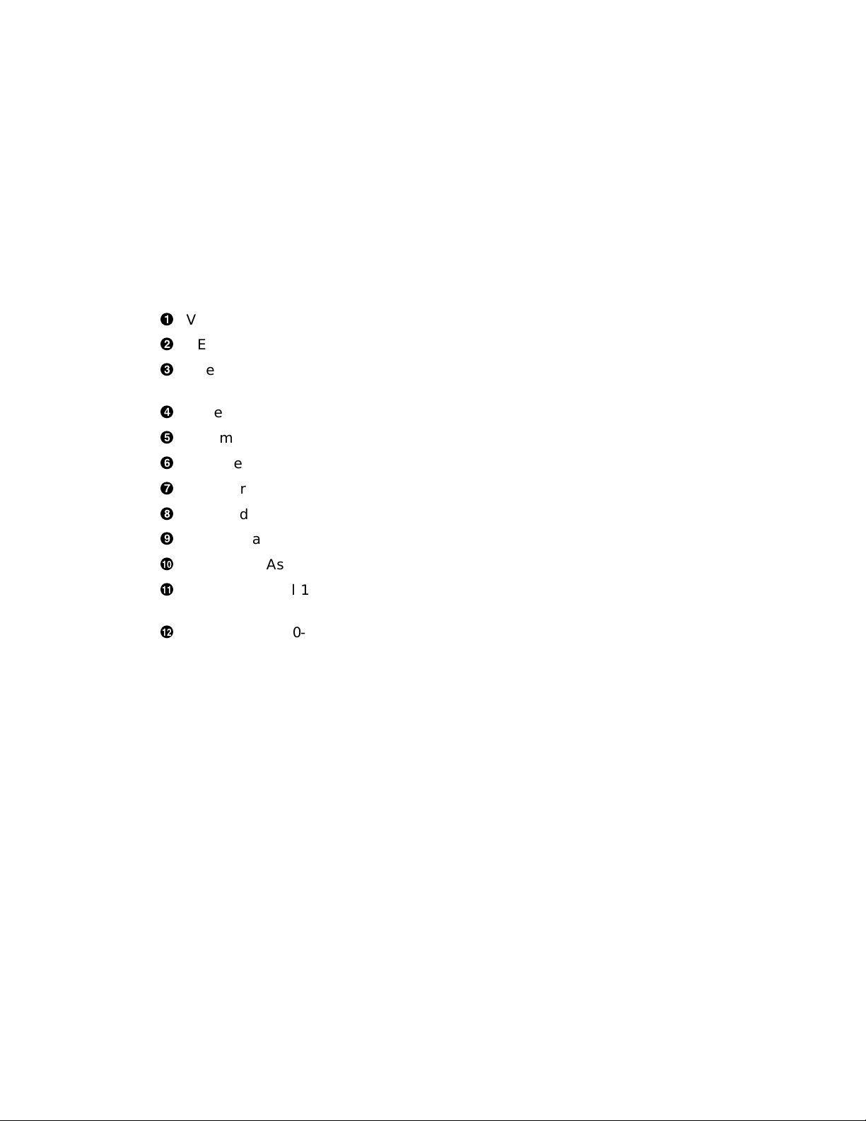
Figure 1–1 RM 4000-10xx System Kit Contents
6
1–4 Installation Procedure
10
11
7
VAX 4000 Model 100A
9
8
cs–10111
Installation Procedure
!
VAX 4000-10xx System Unit
"
DEC423 Terminal Cable (P/N 17-00811-03 / BC16E-25)
#
One ThinWire Ethernet Connector (H8223) and Two Terminators
(H8225)
$
Power Cord (P/N 17-00606-16)
%
Documentation and Software Licenses
&
DSSI Terminator (P/N 12-29258-01)
'
SCSI Terminator H8574-A (P/N 12-30552-01)
(
Standard Ethernet Loopback Connector (P/N 12-22196-01)
)
25-Pin Adapter, D Sub to MMJ (P/N 17-32442-01 / H8575-A)
+>
Screw Lock Assembly (Qty 2) (P/N 90-08451-00)
+?
VAX 4000 Model 100/100A/105A/106A Medallion
(P/N 74-37642-28/31/32/34)
+@
Shelf Kit (P/N 70-30949-01) (See Figure 1–2)
Installation Procedure 1–5
Installation Procedure
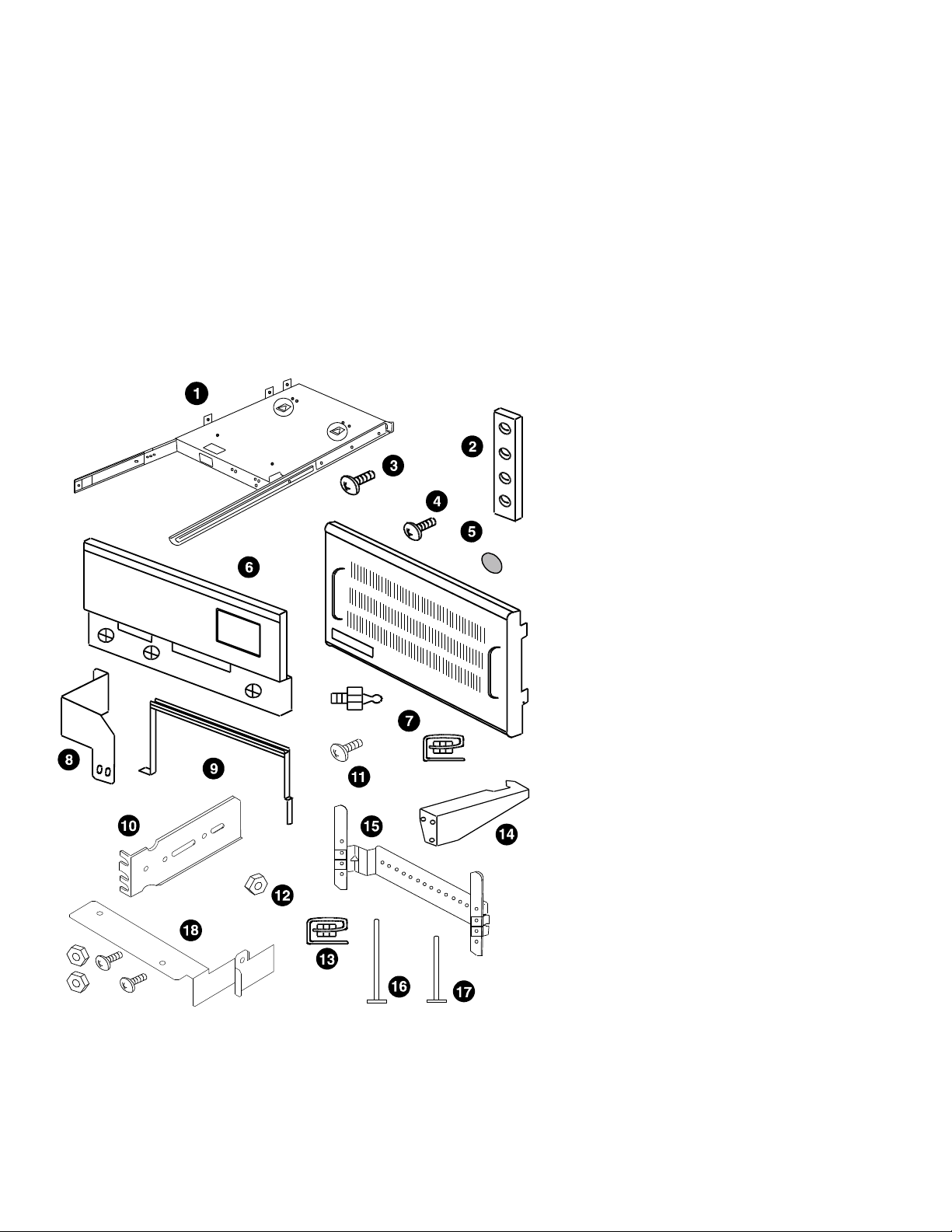
Figure 1–2 RM 4000-10xx Shelf Kit Contents (P/N 70-30949-01)
1–6 Installation Procedure
MLO-011697
Installation Procedure
!
Shelf Assembly
(The shelf comes partially assembled. See Appendix A if shelf is
not assembled.)
"
Chassis Slide Nut Bar, (Qty 4) (P/N 12-32830-01)
#
Screw, Thread, 10-32 x 1/2, (Qty 22) (P/N 90-00063-39)
$
Rackmount VAX 4000 Mounting Screws, (Qty 4) (P/N 90-009984-00)
%
Bumper, Rubber, (Qty 4) (P/N 90-09538-01)
&
Cable Barrier Kit, (Qty 1) (P/N 70-30960-01)
'
Bezel, Vented Installation Kit, (Qty 1) (P/N 70-30934-01):
• U-nut, 10-32, (Qty 4) (P/N 90-07786-01)
• Ball Studs, (Qty 4) (P/N 90-11337-01)
(
Shipping Bracket, (Qty 1) (P/N 74-46848-01)
)
Shipping Strap, (Qty 1) (P/N 74-46849-01)
+>
Mounting Bracket, Long Rear, Both Left and Right (P/N 12-32829-01)
+?
Screw, 8-32 x 3/8, (Qty 10) (P/N 90-00063-22)
+@
Nut, kep 8-32 x .344E, (Qty 8) (P/N 90-06563-00)
+A
U-nut, 10-32, (Qty 8) (P/N 90-07786-01)
+B
Interlock Bracket, (Qty 1) (P/N 74-46988-01)
+C
Cable Management Bracket, (Qty 1) (P/N 74-40319-01)
+D
Tie Wrap, 7 inches, (Qty 2) (P/N 90-07880-00)
+E
Tie Wrap, 11 inches, (Qty 2) (P/N 90-09617-00)
+F
Door Restraining Kit, (Qty 1) (P/N 70-32585-01)
Installation Procedure 1–7

Installation Procedure
Field Installable Upgrade Kits
2. If you are converting a desktop system to an RM 4000-10xx system, ensure
that you have the appropriate kits as described below:
• To convert a VAX 4000 Model 100 to a rackmount VAX 4000 Model
100A with a single DSSI, you need the following items:
– 2T-RAK41-AA Hardware Rackmount Kit (see Figure 1–3 for kit
contents)
– QZ-004AA-FW Firmware Upgrade Kit (refer to packing slip for kit
contents)
– QA-001AA-UW VMS Version 5.5.2H4 (refer to packing slip for kit
contents)
– 74-37642-31 Medallion, VAX 4000 Model 100A
• To convert a VAX 4000 Model 100 to a rackmount VAX 4000 Model
100A with a dual DSSI, you need the following kit:
– 2T-KFDDA-DF Single to Dual DSSI Upgrade and Rackmount Kit
(see Figure 1–4 for kit contents)
• To convert a VAX 4000 Model 100A/105A single/dual DSSI to a
rackmount VAX 4000 Model 100A/105A single/dual DSSI respectively,
you need the following kit:
– 2T-RAK41-AA Hardware Rackmount Kit (see Figure 1–3 for kit
contents)
• To convert a VAX 4000-10xx single/dual DSSI to an RM 4000-106A
single/dual DSSI respectively, you need the following kit:
– 2T-RAK41-AB Hardware Rackmount Kit (see Figure 1–3 for kit
contents)
• To convert a VAX 4000-106A single/dual DSSI to an RM 4000-106A
single/dual DSSI respectively, you need the following kit:
– 2T-RAK41-AC Hardware Rackmount Kit (see Figure 1–3 for kit
contents)
1–8 Installation Procedure

Installation Procedure
• To convert a VAX 4000 Model 100A/105A single DSSI to a rackmount
VAX 4000 Model 100A/105A dual DSSI, you need the following kits:
– 2T-RAK41-AA Hardware Rackmount Kit (see Figure 1–3 for kit
contents)
– 2T-KFDDA-AF Single to Dual DSSI Upgrade Kit (see Figure 1–5
for kit contents)
• To convert a VAX 4000 Model 100/100A single/dual DSSI to a
rackmount VAX 4000 Model 105A single/dual DSSI you need the
following kits:
– 53XR-AA VAX 4000 Model 105A Upgrade Kit (See packing slip for
kit contents)
– 2T-RAK41-AA Hardware Rackmount Kit (See Figure 1–3 for kit
contents)
Installation Procedure 1–9

Installation Procedure
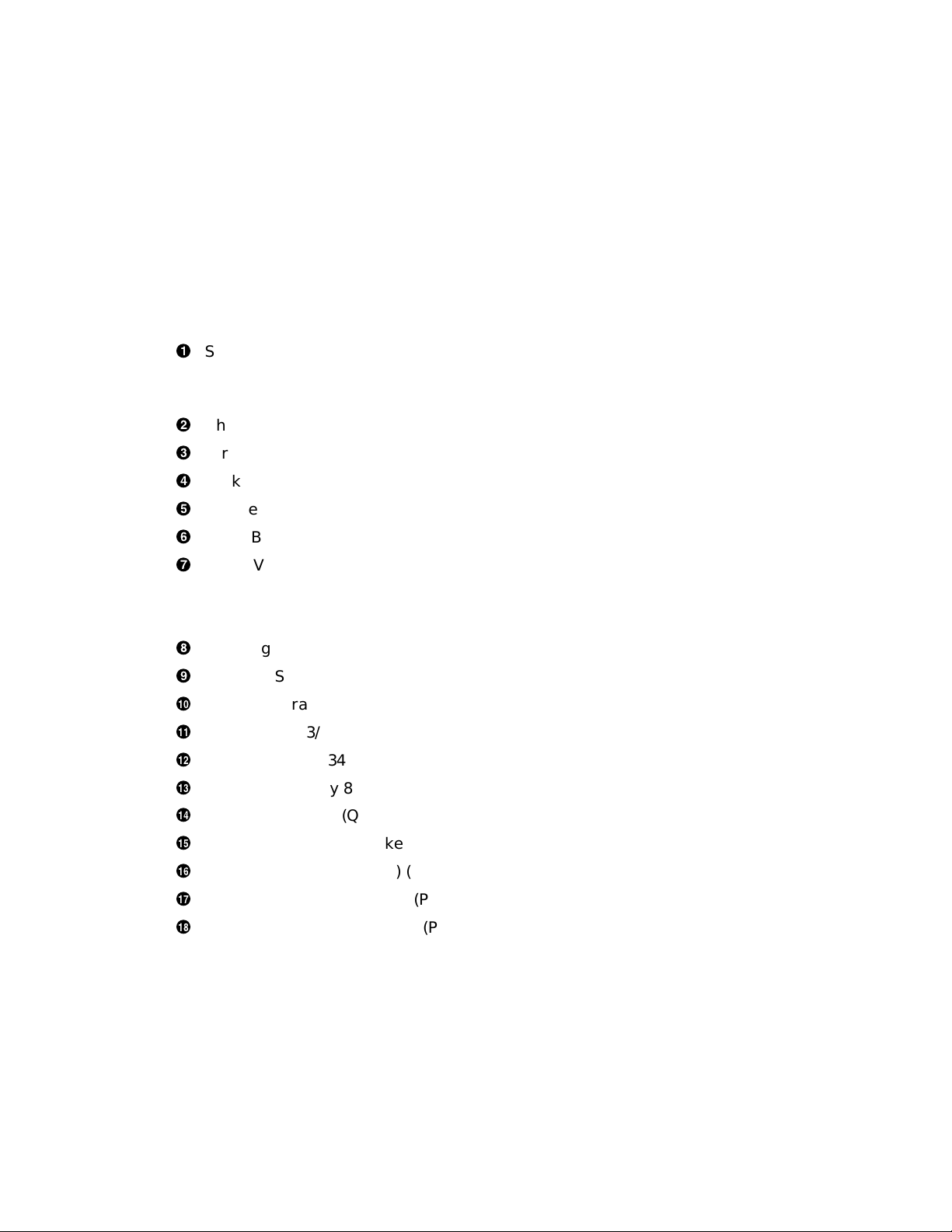
Figure 1–3 2T-RAK41-AA/AB/AC Kit Contents (For Desktop to Rackmount
System Conversion)
9
VAX4000 Model 10xx
10
1–10 Installation Procedure
11
MLO-011698
Installation Procedure
!
VAX 4000 Model 10xx Medallion (P/N 74-37642-31/32/34)
"
Bar Nut (P/N 74-46919-01)
#
DSSI Plate Connector (P/N 74-46668-01)
$
DSSI Plate Screws (Qty 2) (P/N 90-06001-02)
%
Rackmount Cover Assembly (P/N 70-30948-01)
&
Caution Label (Qty 1) (P/N 36-24385-01)
'
Installation Manual (Qty 1) (P/N EK-465RA-IN)
(
Shelf Assembly (Qty 1) (P/N 70-30949-01) (See Figure 1–2)
)
106A CPU Module (Qty 1) (P/N 54-21797-03) (2T-RAK41-AB only)
+>
Internal SCSI Cable (Qty 1) (P/N 17-02542-01) (2T-RAK41-AB/AC only)
+?
DSSI Bus 0 Cable (Qty 1) (P/N 17-04189-01) (2T-RAK41-AB/AC only)
Installation Procedure 1–11

Installation Procedure
Figure 1–4 2T-KFDDA-DF Desktop to Rackmount / Single to Dual DSSI Field
Installable Upgrade Kit Contents
1
3
2
1–12 Installation Procedure
7
QZ–004AA–FW
QA–001AA–UW
4
5
VAX 4000 Model 100A
8
9
6
10
CS–10112
Installation Procedure
!
Dual DSSI Card (Qty 1) (P/N 54-22444-01)
"
Remote DSSI Bus Cable (Qty 1) (P/N 17-03778-01)
#
Machine Screw 2.5 m (Qty 4) (P/N 90-10917-01)
$
DSSI Terminator (Qty 2) (P/N 12-29258-01)
%
Alignment Pin (Qty 4) (P/N 12-30363-01)
&
Washer (Qty 4) (P/N 90-08877-00)
'
Medallion, VAX 4000-10xx (Qty 1) (P/N 74-37642-31)
(
Firmware Upgrade Kit (Qty 1) (P/N QZ-004AA-FW) (refer to packing slip
for kit contents)
)
VMS Version 5.5.2H4 Kit (Qty 1) (P/N QA-001AA-UW) (refer to packing
slip for kit contents)
+>
VAX 4000-10xx Documentation Kit (Qty 1) (P/N QA-00HAA-GZ) (refer to
packing slip for kit contents)
+?
Hardware Rackmount Kit (Qty 1) (P/N 2T-RAK41-AA) (refer to Figure 1–3
for kit contents).
Installation Procedure 1–13
Installation Procedure
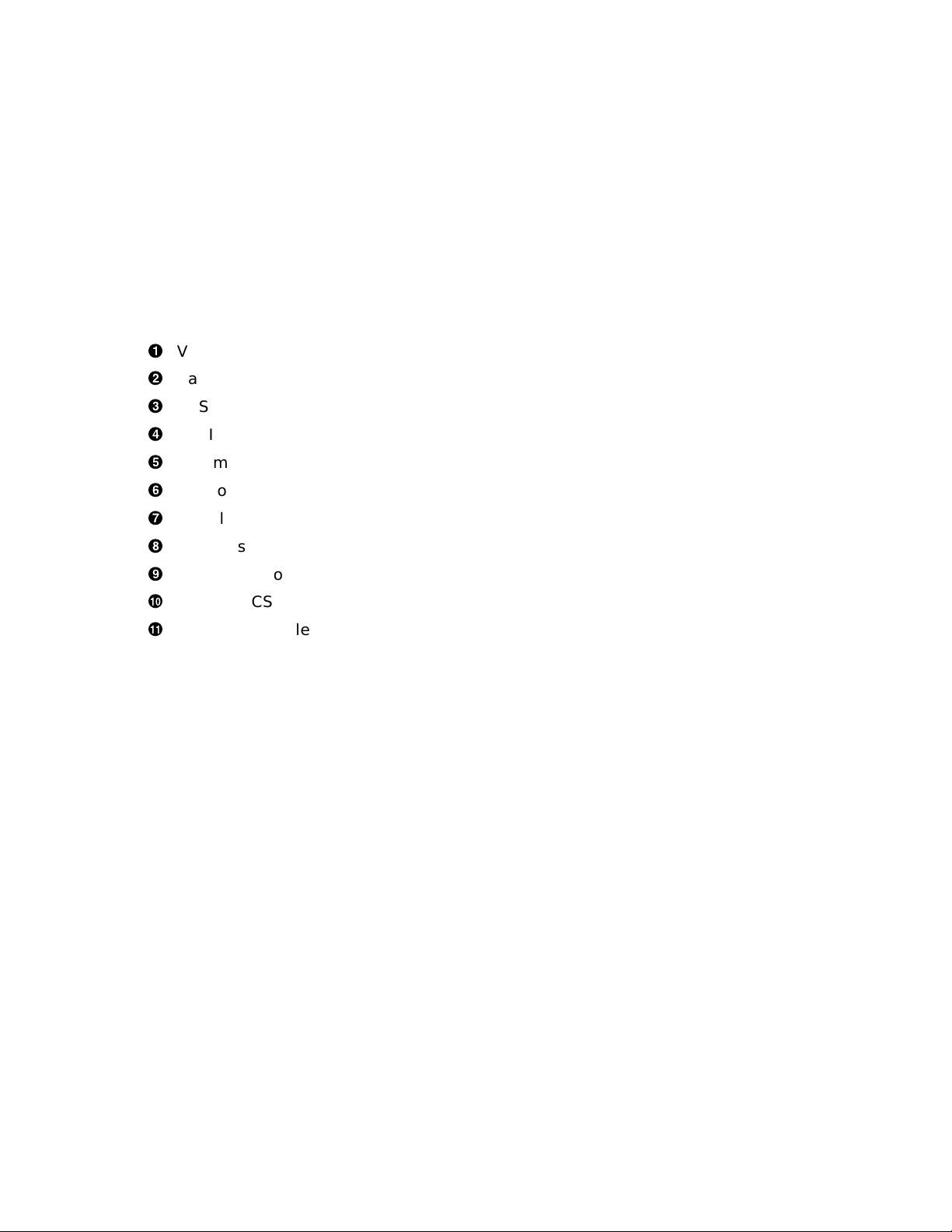
Figure 1–5 2T-KFDDA-AF Single to Dual DSSI Field Installable Upgrade Kit
Contents
1
!
Dual DSSI Card (Qty 1) (P/N 54-22444-01)
"
Remote DSSI Bus Cable (Qty 1) (P/N 17-03778-01)
#
Machine Screw 2.5 m (Qty 4) (P/N 90-10917-01)
$
DSSI Terminator (Qty 2) (P/N 12-29258-01)
%
Alignment Pin (Qty 4) (P/N 12-30363-01)
&
Washer (Qty 4) (P/N 90-08877-00)
2
3
1–14 Installation Procedure
4
5
6
CS–10090

Installation Procedure
Step 3: Convert the VAX 4000-10xx to an RM 4000-10xx with Dual or
Single DSSI
If you do not need to convert your desktop system to a rackmount system,
proceed to Step 4: Install the Shelf Assembly.
To convert a desktop VAX 4000 Model 100 or 100A to a rackmount VAX 4000
Model 100A, perform the following procedure:
1. Ensure that the customer has backed up all data and shut down the
system.
2. If upgrading from a Model 100 to Model 100A, perform the following steps.
Otherwise, go to step 3.
a. Install the VAX 4000-10xx Firmware Version 2.3 Upgrade Kit (P/N
QZ-004AA-FW) if necessary. Use the instructions provided with the kit.
b. Install VMS Upgrade Version 5.5.2H4 (P/N QA-001AA-UW) if
necessary. Use the instructions provided with the kit.
3. If upgrading from a Model 100 or 100A to Model 105A, install the upgrade
kit (P/N 53XR-AA) according to the directions provided with the kit.
Otherwise, proceed to step 4.
4. Turn the power ON/OFF switch, located on the rear of the unit, to the OFF
(O) position.
5. Disconnect the power cable from the unit.
6. Refer to Figure 1–6 and remove the external cables:
a. Remove the external Q–bus cables:
• Slide clip to the left.
• Remove cable.
• Slide clip to the right.
b. Remove the external SCSI cable or terminator.
c. Remove the external DSSI cable or terminator.
d. Remove the Ethernet cable if necessary.
7. Remove the desktop enclosure cover (see Figure 1–6):
a. Loosen (do not remove) the two captive screws!(P/N 12-30338-05) on
the rear of the unit holding the cover in place.
Installation Procedure 1–15

Installation Procedure
b. Remove the cover by sliding it forward and off of the unit.
Figure 1–6 Removing the Desktop Enclosure Cover
!
"
#
$
%
&
8
9
10
1–16 Installation Procedure
'
(
)
+>
Top cover screws (P/N 12-30338-05)
Q–bus mounting hardware
Locking/release tabs (one each side of bustle)
Q–bus connectors
DSSI connector
SCSI connector
2
Rear external bustle cover
DSSI alignment pins (P/N 12-30363-01)
3
DSSI connector screws (P/N 90-10917-01)
SCSI connector screws (P/N 90-09643-00)
1
4
5
6
7
CS–10056
 Loading...