

PL-6900 Series
Panel Computer
User Manual
When printing out this PDF manual, since the printer setting can effect the
quality of the printout, be sure your printer’s quality setting is set to “High”.

i
Preface
PL-6900 Series User Manual
Preface
Digital’s PL-6900 series (PL) of Panel Computers are multipurpose factory
automation (FA) computers, which embody Digital’s latest, cost-effective
architecture. Before using the PL, read this manual thoroughly to familiarize
yourself with the PL’s operation procedures and functions.
1. It is forbidden to copy the contents of this manual in whole, or in part, without the permission of the Digital Electronics Corporation.
2. The information in this manual is subject to change without notice.
3. This manual was written with care; however, if you should find any error or omissions,
please contact Digital Electronics and inform them of your findings.
4. Please be aware that we are not responsible for any damages resulting from the use of
our products, regardless of article 3 above.
Product names used in this manual are the trademarks of their respective manufacturers.
©
Copyright 2000, Digital Electronics Corporation
MS-DOS®, Windows® 95 and Windows NT® are registered trademarks of the
Microsoft Corporation.
IBM®, and DOS® are registered trademarks of IBM.
NOTE:
ii
Preface
PL-6900 Series User Manual
This manual includes the following cautions concerning procedures that must be
followed to operate the PL correctly and safely . Prior to operating the PL, be sure to
read this manual and any related materials thoroughly to understand the correct operation and functions of this unit.
Safety Icons
To allow you to use the PL correctly , throughout this manual, the following icons
are provided next to operations requiring special attention. These icons are used to
describe the following situations:
Indicates situations where severe bodily
injury, death or major equipment damage
may occur.
Indicates situations where slight bodily
injury or machine damage can occur.
Caution
W arning
Essential Safety Precautions
• To avoid the possibility of an electric shock, be sure to
connect the power cord to the PL before connecting it to
the main power supply.
• A fire or electrical shock may occur if voltages used with
the PL are beyond the specified range. Be sure to use only
the specified voltage.
• Before opening the PL’s protective cover, be sure to turn
the unit’s power OFF. This is because the PL’s internal
parts carry high voltages.
• T o avoid fires or electrical hazards, do not modify the PL in
any way.
• Do not create touch panel switches that are used to either
control or to ensure the safety of equipment and personnel. Mechanical switches, such as an emergency stop
switch, a deadman (two-handed) start switch, etc., must
be installed and operated via a separate control system.
WARNINGS

iii
Preface
PL-6900 Series User Manual
• After the PL’s backlight burns out, unlike the PL’s
“Standby Mode”, the touch panel is still active. If the operator fails to notice that the backlight is burned out and
touches the panel, a potentially dangerous machine missoperation can occur.
If your PL's backlight suddenly turns OFF, use the following
steps to determine if the backlight is actually burned out.
1) If your PL is
not set to "Standby Mode" and the screen
has gone blank, your backlight is burned out.
2) Or , if your PL
is set to Standby Mode, but touching the
screen does not cause the display to reappear, your
backlight is burned out.
• If metal particles, water or other types of liquids contact
any of the PL’s internal parts, immediately turn the unit’s
power OFF, unplug the power cord, and contact either
your PL distributor or the Digital Electronics Corporation.
• Read and understand Chapter 4 “Installation and Wiring”
thoroughly in order to select an appropriate installation
location for the PL.
• Before either plugging in or unplugging a board or inter-
face connector, be sure to turn the PL’s power OFF.
WARNINGS
• Do not create touch panel switches which could possibly
endanger the safety of humans and equipment. This is due
to the possibility of a malfunction in the PL or its cable(s),
causing the output of a signal that could result in a major
accident. All of a system’s major, safety-related switches
should be designed to be operated separately from the PL.

iv
Preface
PL-6900 Series User Manual
WARNINGS
• To prevent a possible explosion, do not install the PL in
areas containing flammable gases.
• The PL is not appropriate for use with aircraft control
devices, aerospace equipment, central trunk data transmission (communication) devices, nuclear power control
devices, or medical life support equipment, due to these
devices’ inherent requirements of extremely high levels of
safety and reliability.
• When using the PL with transportation vehicles (trains,
cars and ships), disaster and crime prevention devices,
various types of safety equipment, non-life support related medical devices, etc. redundant and/or fail-safe
system designs should be used to ensure the proper degree of reliability and safety.
v
Preface
PL-6900 Series User Manual
• Do not push on the PL’s screen too strongly, with either
your finger or with a hard object. Excessive pressure can
scratch, crack or damage the screen. Also, do not use a
pointed object, such as a mechanical pencil or screwdriver, to press any of the touch panel’s switches, since
they can damage the display.
• If the screen becomes dirty or smudged, moisten a soft
cloth with diluted neutral detergent, wring the cloth well,
and wipe the display. Do
not use thinner or organic sol-
vents.
• Avoid exposing the PL to, or operating the PL in direct
sunlight, high temperatures and humidity, and in areas
where excessive dust and vibration will occur.
• Avoid using the PL in areas where sudden, extreme
changes in temperature can occur. This may cause condensation to form inside the unit, possibly leading to an
accident.
• To prevent the PL from overheating, be sure its air circula-
tion vents are clear and clean, and keep the unit’s operation area well-ventilated.
• Avoid operating or storing the PL near chemicals, or
where chemicals can come into contact with the unit.
When PL Hard Disk (HDD) data is lost:
• The Digital Electronics Corporation can not be held re-
sponsible or provide any compensation for damage(s)
caused by the loss of data stored in the PL’s hard disk
drive (HDD). It is therefore strongly suggested that all
important data and software be backed up regularly to an
external data backup device.
• Please be aware that the Digital Electronics Corporation
bears no responsibility for any damages resulting from the
customer’s application of this unit’s hardware or software.
CAUTIONS

vi
Preface
PL-6900 Series User Manual
The displayed color will look different when viewed from an angle outside the
specified view angle. This is also normal.
Displaying a single screen image for long periods of time can cause an afterimage
to remain on the screen. To correct this, turn the unit OFF for 5 to 10 minutes,
then ON again. This phenomenon is a common attribute of the LCDs, and is not
a defect. To prevent this effect, you can:
- use the Display OFF feature; if the same image is to be displayed for a long
period of time.
- change the screen display periodically to prevent the displaying of a single
image for a long period of time.
Notes on Handling the Hard Disk Drive
The Digital Electronics Corporation cannot take responsibility or provide any
compensation for damage(s) caused by the loss of data stored in the PL-6900
series’ hard disk drive (HDD). It is therefore strongly suggested that all important data and software be backed up regularly to an external data backup device.
Please be aware that the Digital Electronics Corporation bears no responsibility
for any damages resulting from the customer’s application of this unit’s hardware or software.
Please be aware that the Digital Electronics Corporation will not provide com-
pensation for any damages occurring as a result of problems with this unit’s
software or hardware.
Since the PL’s hard disk drive (HDD) is a consumable item, i.e. it has a finite
usage lifetime, be sure to back up its data frequently and perform regular maintenance.
T o prevent damage to file data, be sure to shut down the PL’s OS before turning
OFF the main power.

vii
Preface
PL-6900 Series User Manual
Table of Contents
Preface
Preface .......................................................................................................................... i
Essential Safety Precautions........................................................................................ ii
Table of Contents....................................................................................................... vii
Prior to Using the PL................................................................................................... x
Information Symbols .................................................................................................. xi
Package Contents ...................................................................................................... xii
PL-6900 Series Features........................................................................................... xiii
UL/cUL Application Notes ...................................................................................... xiv
CE Marking ............................................................................................................... xv
Chapter 1 Overview
1-1 System Configuration ...................................................................................... 1-1
1-2 Options .............................................................................................................. 1-2
1-3 PL Series Panel Types...................................................................................... 1-5
Chapter 2 Specifications
2-1 General Specifications .................................................................................... 2-1
2-1-1 Electrical Specifications ....................................................................... 2-1
2-1-2 Environment Specifications..................................................................2-2
2-1-3 Dimensions ........................................................................................... 2-3
2-2 Performance Specifications............................................................................2-4
2-2-1 Performance Specifications .................................................................. 2-4
2-2-2 Display Functions ................................................................................. 2-5
2-2-3 Expansion Slots .................................................................................... 2-5
2-2-4 Clock(R TC) Accuracy .......................................................................... 2-5
2-3 Interface Specifications ..................................................................................2-6
2-3-1 Printer Interface .................................................................................... 2-6
2-3-2 Keyboard Interface ............................................................................... 2-6
2-3-3 Mouse Interface .................................................................................... 2-6
2-3-4 RS-232C Interface (COM1/COM2/COM3) ......................................... 2-7
2-3-5 RAS Interface ....................................................................................... 2-7
2-4 PL External Features......................................................................................2-9
2-5 PL Dimensions............................................................................................... 2-11
2-5-1 PL-6900T General Dimensions .......................................................... 2-11
2-5-2 PL-6901T General Dimensions .......................................................... 2-12
2-5-3 Full Sized Cover Attachment Dimensions ......................................... 2-13
2-5-4 Installation Slot Dimensions...............................................................2-14

viii
Preface
PL-6900 Series User Manual
Chapter 3 Installing Optional Units and Expansion Boards
3-1 Installing Options and Expansion Boards ..................................................... 3-1
3-1-1 Removing the rear maintenance cover ................................................. 3-2
3-1-2 Installing the DIM Module (PL-EM220 / PL-EM230)......................... 3-4
3-1-3 Installing the FDD Unit (PL-FD200).................................................... 3-5
3-1-4 Installing the FDD Unit (PL-FD210).................................................... 3-6
3-1-5 Removing/Installing the HDD unit (PL-HD220) ................................. 3-8
3-1-6 Installing an Expansion Board.............................................................. 3-9
3-1-7 Connecting the CD-ROM Unit (PL-DK200) ..................................... 3-10
3-1-8 Removing the Cooling Fan Unit......................................................... 3-1 1
Chapter 4 Installation and Wiring
4-1 Installation Cautions........................................................................................ 4-1
4-2 Installing the PL ............................................................................................... 4-3
4-2-1 Installation Procedures ......................................................................... 4-3
4-3 Wiring the PL ................................................................................................... 4-6
4-3-1 Connecting the Power Cord.................................................................. 4-6
4-3-2 Power Supply Cautions ........................................................................ 4-8
4-3-3 Grounding Cautions.............................................................................. 4-9
4-3-4 Cautions When Connecting I/O Signal Lines....................................... 4-9
Chapter 5 System Setup
5-1 Setup Procedures.............................................................................................5-1
5-2 System Parameters.......................................................................................... 5-2
5-2-1 STANDARD CMOS SETUP ............................................................... 5-2
5-2-2 BIOS FEATURES SETUP ................................................................... 5-4
5-2-3 CHIPSET FEATURES SETUP ............................................................ 5-6
5-2-4 POWER MANAGEMENT SETUP ..................................................... 5-8
5-2-5 PNP/PCI CONFIGURATION SETUP ............................................... 5-10
5-2-6 SYSTEM MONITOR UTILITY ........................................................ 5-12
5-2-7 INTEGRATED PERIPHERALS ........................................................ 5-14
5-2-8 IDE HDD AUTO DETECTION SETUP ........................................... 5-16
Chapter 6 OS Setup
6-1 Setting Up Your PL OS .................................................................................. 6-1
6-1-1 Touch Panel Device Driver Settings ..................................................... 6-2
Chapter 7 Maintenance and Inspection
7-1 Regular Cleaning ............................................................................................ 7-1
7-1-1 Cleaning the Display............................................................................. 7-1
7-1-2 Moisture Resistant Gasket Replacement .............................................. 7-2
7-2 Cleaning the Filter ..........................................................................................7-2

ix
Preface
PL-6900 Series User Manual
7-3 Changing the PL Backlight............................................................................ 7-4
7-4 Periodic Check................................................................................................ 7-9
Appendix
1 Hardware Configuration............................................................................... A-1
1-1 I/O Mapping ........................................................................................ A-1
1-2 Memory Mapping ................................................................................ A-2
1-3 IRQ Mapping ....................................................................................... A-3
2 RAS Feature ................................................................................................... A-4
2-1 PL’s RAS Features............................................................................... A-4
2-2 RAS Feature Details ............................................................................ A-5
2-3 RAS Feature Overview........................................................................ A-9
Index
x
Preface
PL-6900 Series User Manual
The PL’s hard disk is designed for use with the Windows
®
95, Windows NT®4.0
or later OS. The Mirror Disk unit will operate only with the Windows NT®4.0
operating system. Other operating systems do not support this driver software,
etc.
For system setup and OS installation, a PS/2 type keyboard is necessary.
When using Windows
®
95/Windows NT®4.0, be sure to install the PL-6900 Series
Driver & Utility Disk’s Display Driver (For installation procedur es, see the disk’s
readme files (README.95E or README.NTE).
For information on the PL’s bundled utility software, see the README file on
the Driver & Utility Disk.
Since the PL’s hard disk drive (HDD) is a consumable item, i.e. it has a finite
usage lifetime, be sure to back up its data frequently and perform regular maintenance.
After turning the PL OFF, be sure to wait at least 5 seconds before turning ON
again. If the unit is stated within 5 seconds, it may not start up correctly.
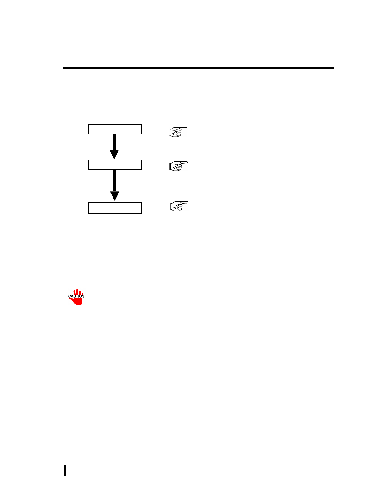
Prior To Using the PL
Prior to actual use, be sure to setup your PL as follows.
Turn PL ON Refer to 4-3 Wiring the PL
Setup System Refer to Chapter 5 System Setup
Refer to the OS maker’s Installation Manual.
After completing the hardware setup, before any data or applications can be placed on
the drive, the OS (Windows® or MS-DOS®, etc.) must be used to initialize the HDD and
create partitions. For details concerning these procedures, refer to the OS maker’s
installation manual.
Install the OS
xi
Preface
PL-6900 Series User Manual
Information Symbols
This manual uses the following icons:
Indicates a warning or a product limitation. Be sure to follow the instructions given with this icon to insure the safe operation of the PL.
Contains additional or useful information.
Indicates terms or items that require further explanation. See the footnote
on that page.
Indicates pages containing related information.
Indicates steps used to accomplish a given task. Be sure to follow these
steps in the order they are written.
*
1), 2)
xii
Preface
PL-6900 Series User Manual
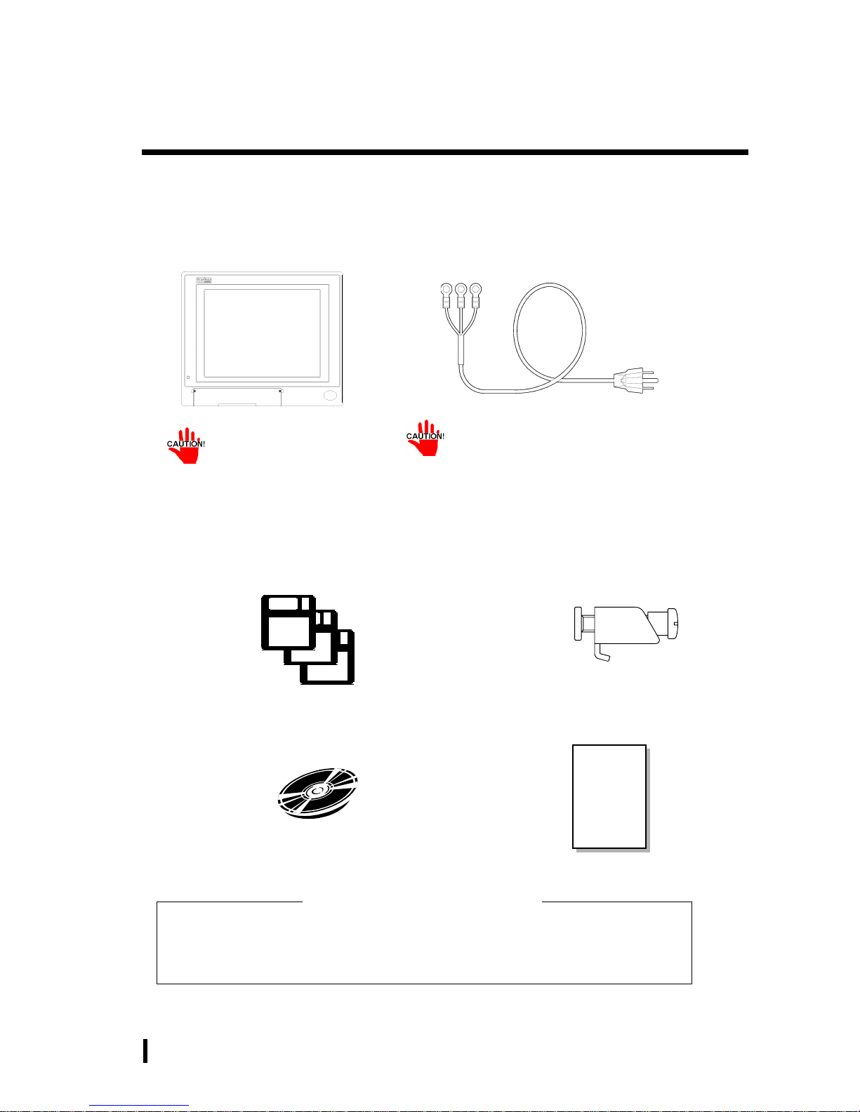
Package Contents
The PL package should include the following items:
Be careful when installing the PL not to damage the built-in HDD
Power Cord
PL Unit
(PL-6900T/PL-6901T)
This cord is designed only for AC100/115V
use. Any other voltage will require a different cable.
Installation Brackets (8)
Floppy Disks (3)
“PL-X900 Series Driver & Utility Disk”
CD-ROM (1)
Contains PL-6900 Series
User Manual (This Manual)*
Your PL unit package will also contain an Installation Guide for your
built-in HDD unit.
Be sure to check that guide’s package contents.
If your PL contains a built-in HDD
Instruction
Guide
Instruction Guide
(English1/Japanese1)

xiii
Preface
PL-6900 Series User Manual
PL-6900 Series Features
The PL-6900 series displays are equipped with the following features:
The Latest, High-Performance Architecture
Designed around the AMD-K6®-2 333 MHz CPU, the PL utilizes the type of high
performance architecture that offers you superior compatibility. Add to this unrivalled support of the Windows®95/Windows NT® and other operating systems.
Bright 12.1" LCD with a Wide Viewing Angle
The PL’s large 12.1-inch 800 x 600 dot TFT LCD display offers excellent visibility and brightness.
• Digital’s top of the line TFT color LCD model allows you to create detailed
and powerful visual images, with excellent brightness, a wide viewing angle,
and a display capable of 260,000 colors.
Easy Front Panel Installation
The PL is designed to be installed easily into the front of any panel or device. It
is also rugged enough for use in harsh, industrial environments, such as those
found in the factory automation industries and boasts an IP65f rating.
High Resolution, Analog-Resistance-Film Touch Panel
Standard equipment with the PL is a high resolution 1024 x 1024 touch panel.
Also, the Windows® 95 mouse emulation utility provides mouse-like functionality and pointer control.
Highly Expandable
The PL units consist of two types; a 2 slot type (with 1 PCI bus also available),
and a 4 slot type (with 2 PCI buses available). These slots can accommodate
both Digital’s own optional boards as well as other commercially available expansion boards.
Digital also offers a wide variety of optional products, such as a -5/-12V DC
power unit, DIM memory modules, etc.

xiv
Preface
PL-6900 Series User Manual
UL/cUL Application Notes
The PL690*-T4* is (c)UL 1950 recognized product. (UL File No. E171486). Please pay special attention to the following instructions when applying for UL/cUL approval for machinery
which includes any of these PL units.
The PL conforms as a component to the following standards:
UL 1950, Third Edition, dated March 1,1998 (Standard for Safety of Information T echnology Equip-
ment, including Electrical Business Equipment)
CSA-C22.2 No. 950-95 (Standard for Safety of Information T echnology Equipment, including Electrical
Business Equipment)
PL6900-T4* (UL Registration Model No.: 2780054-04)
PL6901-T4* (UL Registration Model No.: 2780054-03)
- Equipment with a PL mounted in it requires UL/cUL evaluation for the combination of the
PL and equipment.
- The PL must be used as a built-in component of an end-use product.
- Use the PL indoors only.
- When connecting the PL’s power cable, be sure to use a cable that is appropriate for the
current and voltage used and that has conductive wires that are 0.75 mm2 or larger.
- With an end-use product which includes the PL, be sure to place the PL’s Power cut-off
switch as the disconnect device where the unit’s operator can easily reach it.
- Danger of explosion if backup battery is incorrectly replaced. Replaced only with same or
equivalent type recommended by the manufacturer. Dispose of used batteries according to
the manufacturer’s instructions.
- Be sure the unit the PL is built into uses a UL1950 compatible equipment structure.

xv
Preface
PL-6900 Series User Manual
CE Marking
The PL690*-T4* units are CE marked, EMC compliant products.
<Complies with the following Standards>
Safety
EN60950
EMI (EN50081-2)
EN55011 group1 (Class A)
EMS (EN50082-2)
EN61000-4-2, EN61000-4-3, EN61000-4-4,
EN61000-4-6, EN61000-4-8, ENV50204
If following requirements are not met, the PL may fail to meet EN60950 standard requirements.
Equipment with a PL mounted in it requires UL/cUL evaluation for the combination of the
PL and equipment.
The PL must be used as a built-in component of an end-use product.
Use the PL indoors only.
When connecting the PL’s power cable, be sure to use a cable that is appropriate for the
current and voltage used and that has conductive wires that are 0.75 mm2 or larger.
When installing the PL in a metal panel or cabinet, be sure to place the PL’s Power discon-
nect device (cut-off switch) where the unit’s operator can easily reach it.
There is a danger of explosion if the backup battery is incorrectly replaced. This battery
should be replaced only with same or equivalent type recommended by the manufacturer.
Dispose of used batteries according to the manufacturer’s instructions.
Be sure the cabinet/enclosure the PL is built into uses an EN60950 approved sheet steel structure.

xvi
Preface
PL-6900 Series User Manual
MEMO
1 - 1
PL-6900 Series User Manual
Overview
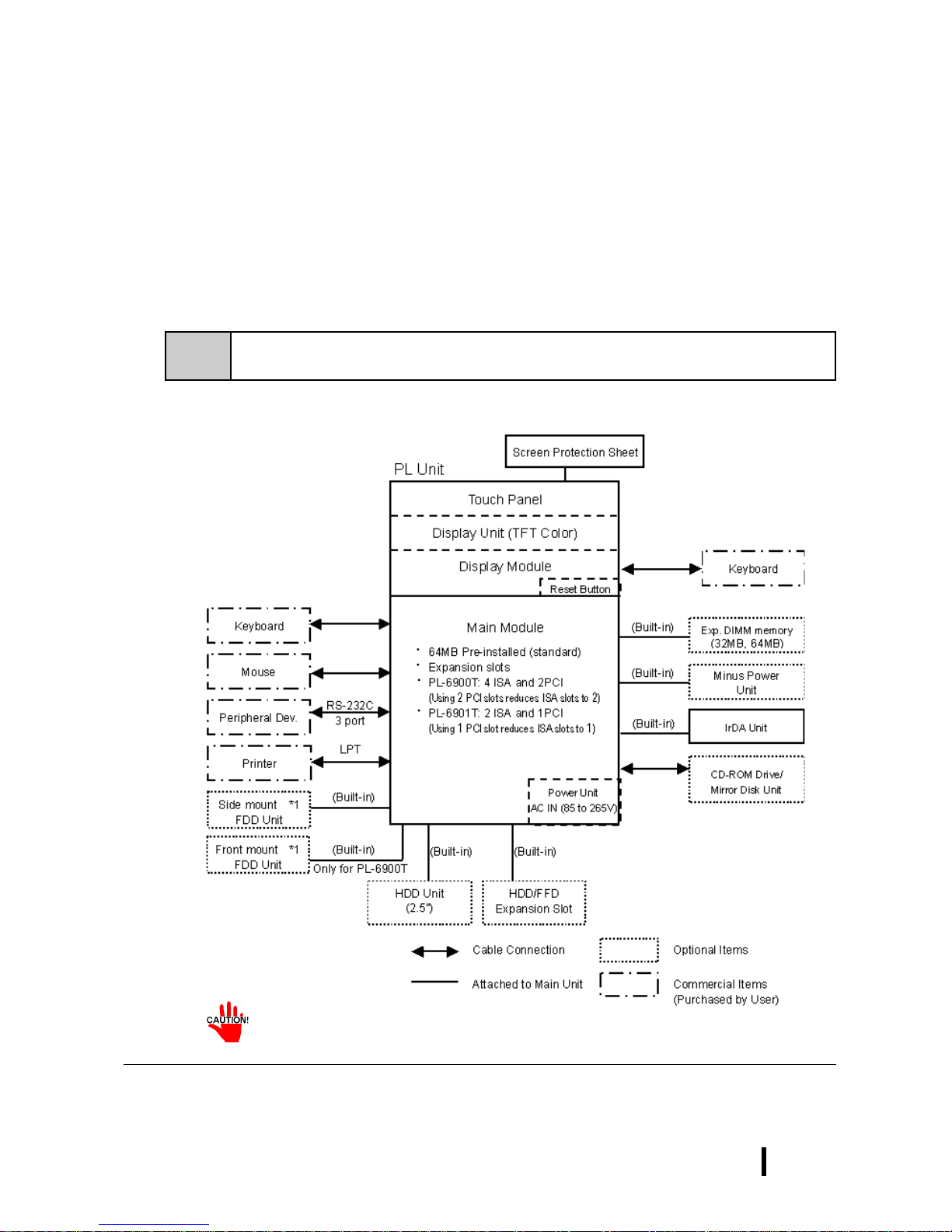
1-1 System Configuration
Chapter
1Overview
1-1 System Configuration
1-2 Options
1-3 PL Series Panel Types
The following chart shows the range of peripheral items connected to the PL.
• Only one FDD unit can be used at one time, i.e. either the front panel’s
FDD, or the main unit’s FDD.
*1 Only one FDD unit can be used at one time, i.e. either the front panel’s FDD, or the main
unit’s FDD.
1 - 2
PL-6900 Series User Manual
Overview
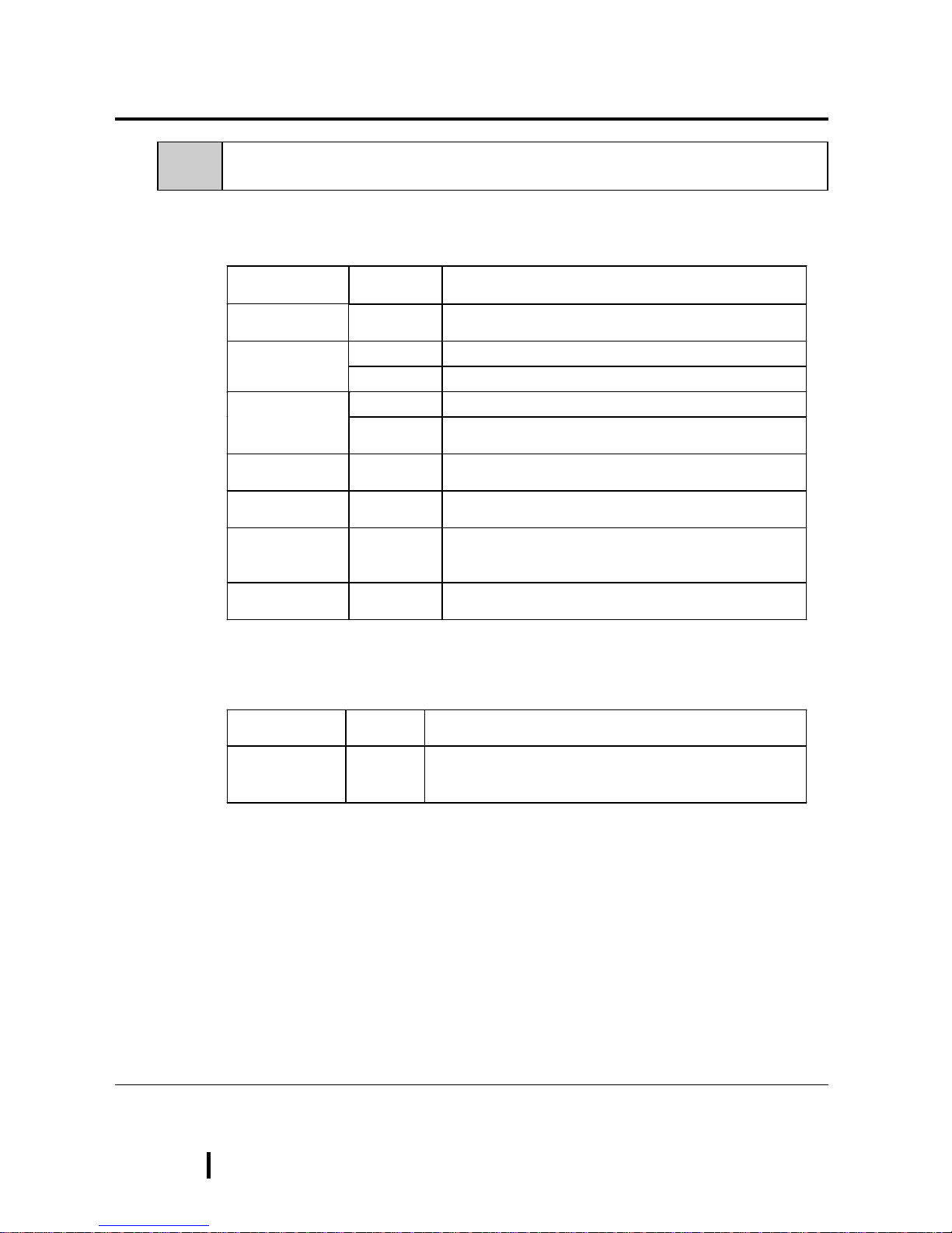
Name
Model
number
Description
LAN Board DAX-IET02 NE2000 compatible board. Provides connectors for
10BASE-5, 10BASE-2 and 10BASE-T.
PL-EM220 SDRAM (DIMM) Provides 32MB of memory DIM Module
PL-EM230 SDRAM (DIMM) Provides 64MB of memory
PL-FD200 *1 IBM PC Compatible 3.5” FDD unit (Attaches to side slot) FDD Unit
PL-FD210 *
1
IBM PC Compatible 3.5” FDD unit (Attaches to front slot)
Only for PL-6900T
-5V/-12V Power
Unit
PL-PW100 Provides –5V and –12V power to expansion slots. Can
provide a total of 200mA of current (sum of both slots).
FFD Unit
(Flash File Disk)
PL-FF200 Flash File Disk Provides 20MB of memory, connected to
IDE I / F. Used as HDD.
CD-ROM Unit PL-DK200 IDE (ATAPI) compliant CD-ROM drive unit
– for development and maintenance use.
(special connection cable is included with unit)
Mirror Disk Unit PL-MD200-H
U01
IDE compliant mirror disk unit without OS
Name
Model
number
Description
Screen
Protection Sheet
PL-CS100
Disposable overlay sheets for display face protection and
stain resistance. Touch panel senses User’s touch
through sheet. (5 sheets/set)
1-2 Options
The following table provides a list of optional products for the PL
Expansion Options
Accessories
*1 Both the PL-FD200 and the PL-FD210 cannot be used at the same time.
1 - 3
PL-6900 Series User Manual
Overview
Name
Model
number
Description
Mounting
Brackets
GP070-AT
01
Used to install the PL into a panel or cabinet. Same as
original equipment brackets. (4 brackets/set)
Moisture
Resistant Gasket
PL-WS100
Used to prevent moisture from entering into the PL’s case
from the front face. Same as original equipment gasket.
HDD Unit PL-HD220
2.5” HDD unit (10.0GB or larger - contains no pre-installed
OS
Mirror Disk Unit
Replacement HDD
PL-MD200MD01
Mirror Disk Unit’s replacement HDD (1).
PL-FC200
Attached when ISA bus full sized board is used in the
expansion slot. (for PL-6901T)
Full-sized cover
PL-FC210
Attached when ISA bus full sized board is used in the
expansion slot. (for PL-6900T)
Backlight GP675T-BL
00-MS
Spare Backlight for maintenance.
Maintenance Options
• Since the PL’s hard disk drive (HDD) is a consumable item, i.e. it has a
finite usage lifetime, be sure to back up its data frequently and perform
regular maintenance.
• Both the PL-FD200 and the PL-FD210 cannot be used at the same time.
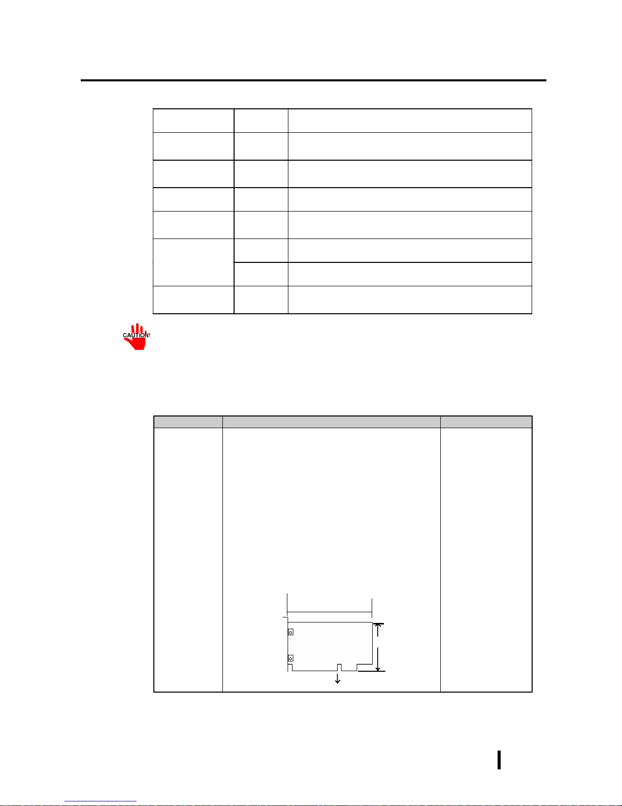
Product Description Installation Area
PCI/ISA Bus
compatible
board
In all PL-6900 series units, slot 1 can accommodate
boards up to 163mm wide. Slot 2 (slots 2, 3 and 4 for
PL-6900T) can accommodate boards up to 250mm
wide.
■■■■
All PL-6900 series slot heights are 122mm. When
using the full-sized cover, be sure to use boards
that are no more than 338mm wide and 122mm
high in slot 2.
■■■■
The height of the devices attached to the face of
an expansion board can be, for slot 1 (slots 1 and
4 for PL-6900T), up to 13mm, and for slot 2 (slots
2 and 3 for PL-6900T), up to 18mm.
Into the PL's expansion slots.
Commercially Available Products
^
^
Width
Height
Attaching Direction

1 - 4
PL-6900 Series User Manual
Overview
<Expansion Slot’s Width and Power Supply>
• Check that your expansion board’s “foot” matches the width of the
expansion slot. Slot 1 (slot 1 and 4 for PL-6900T) is 20 mm wide, and
slot 2 (slot 2 and 3 for PL-6900T) is 25 mm wide. Be sure the width of
your expansion board’s width matches that of the intended slot.
<Power Supply>
• Since the PL does not supply -5 and -12 V current, ISA(A T)-bus compatible boards requiring -5 or -12 V can be used only if the optional PLPW100 power supply is installed.
<Commercially Available Boards>
• Certain commercially available boards may not be compatible with
Digital’s PL unit. Installing incompatible boards may result in either
damage to or failure of the PL and will void your warranty. Prior to
using those boards, be sure to contact your local PL distributor.
<PCI Bus>
• Within the entire range of PCI buses currently available on the market,
there may be certain devices which will not operate when used with the
PL. Prior to the use of any PCI Bus, be sure to contact your local PL
distributor.
<Main Memory>
• Be sure to use only DIM modules manufactured by Digital. Installing
other DIM modules may result in either damage to or failure of the PL,
and will void your warranty.
<When using Standard PC Peripheral Devices>
• Within the range of peripheral devices currently available on the market,
there may be certain devices which will not operate correctly when used
with the PL. Prior to using any peripheral device, be sure to contact your
local PL distributor. Installing incompatible boards may result in either
damage to or failure of the PL and will void your warranty.
1 - 5
PL-6900 Series User Manual
Overview
A
PL690 PL-6900 Series Unit
0 4-slot type
B
1 2-slot type
C
T TFT Color LCD display
D
4 CE Marking, UL/cUL Approval
E
X PL Revision No.
1-3 PL Series Panel Types
PL690 X-T X X-XX XX
ABCDE FG
Model Number:

1 - 6
PL-6900 Series User Manual
Overview
MEMO
2 - 1
PL-6900 Series User Manual
Specifications
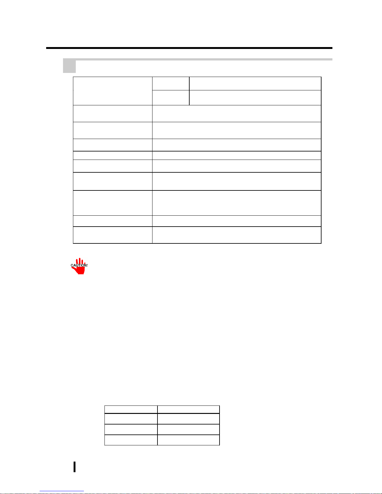
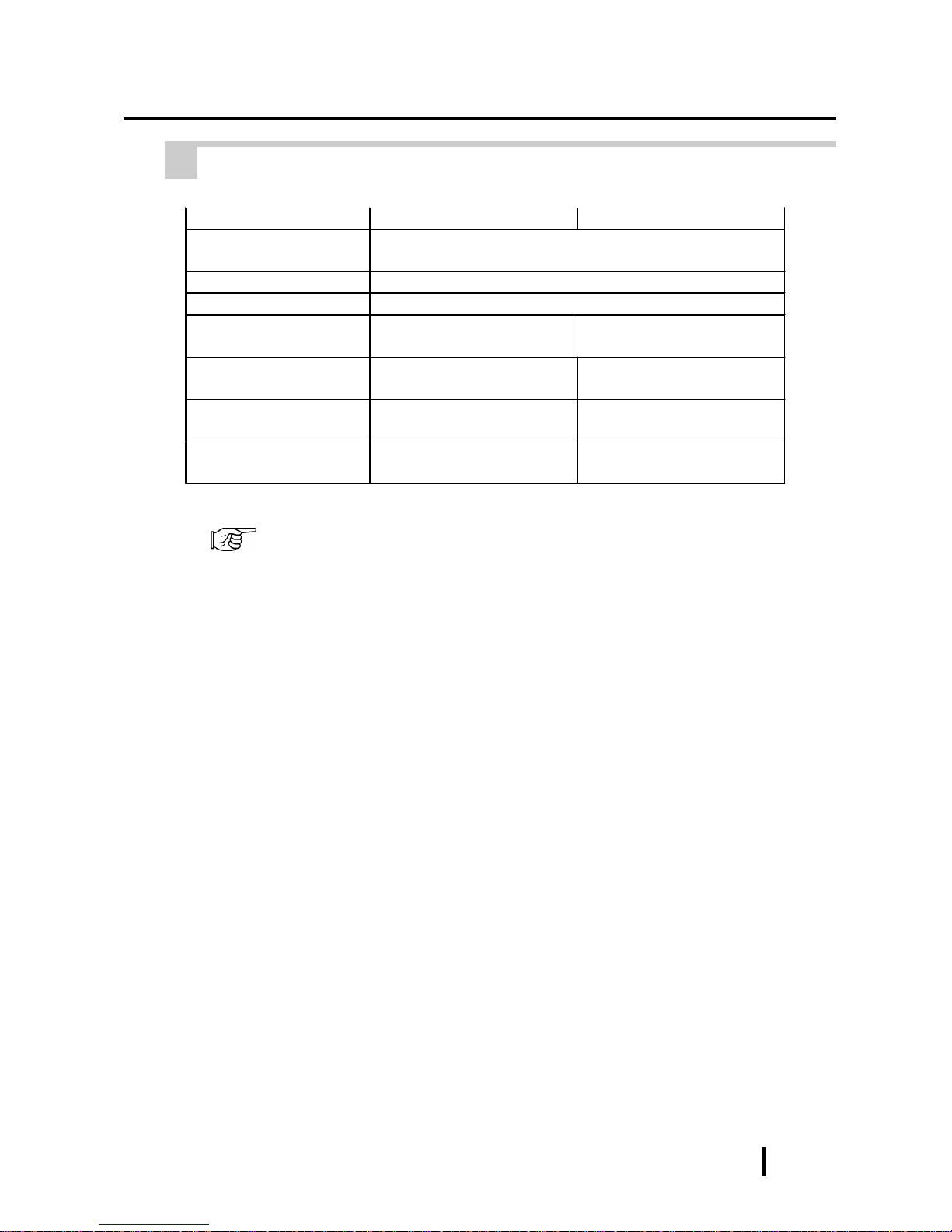
PL-6900T PL-6901T
Operating Voltage AC 100V to AC 240V
Voltage Endurance AC 85V to AC 265V
Rated Frequency 50/60Hz
Allowable Pause
Duration
shorter than 1 cycle (however, pause occurrences must be more than 1
second apart)
Power Consumption less than 150VA less than 100VA
Voltage Endurance
AC 1500V at 20mA for 1 minute
(between the live wire and the grounding (FG) terminal)
Insulation
Resistance
Greater than 10MΩΩΩΩ at DC 500V
(between the live wire and the grounding (FG) terminal)
Chapter
2Specifications
2-1 General Specifications
2-2 Performance Specifications
2-3 Interface Specifications
2-1 General Specifications
2-4 PL External Features
2-5 PL Dimensions
1 Electrical Specifications
2 - 2
PL-6900 Series User Manual
Specifications
• When using any of the PL’s optional devices, be sure to check that device’s
specifications for any special conditions or cautions that may apply to its use.
• When using a full sized expansion board, be sure to check its dimensions and
shape, since they will affect the board’s environment specifications, such for
vibration, etc.
• Be aware that not only does the Hard Disk have a fixed lifetime, but that
accidents can always occur. Therefore, be sure to back up your Hard Disk’s
data regularly , or prepare another Hard Disk unit that can be used for backup.
• The Hard Disk lifetime given here may be reduced due to unforeseen environmental factors, however , generally speaking, at an operating temperatur e of 20oC the
disk should last for 20,000 hours (of operation) or approximately 5 years, whichever comes first.
• Using the Hard Disk in an environment that is excessively hot and/or humid
will shorten the disk’s usage lifetime. A maximum wet bulb temperature of
29oC or less is recommended. This is equivalent to the following data.
*1 The PL’s internal cooling fan is removed.
Tempera ture Humidity
at 35oC no higher t han 7 1%RH
at 40
o
C no higher t han 5 4%RH
at 50
o
C no higher t han 3 3%RH
2 Environment Specifications
W/Fan
0
o
C to 50oC
Ambient Operating
Temperature
(Panel Interior&Panel Face)
W/out Fan
*1
0
o
C to 40oC
Ambient Storage
Temperature
-10
o
C to 60 oC
Ambient Operating
Humidity
30% RH to 85% RH (no condensation)
Ambient Storage Humidity
30% RH to 85% RH (no condensation)
Dust Level Free of dust
Operating Atmosphere
Free of corrosive gas
Vibration Endurance
2G: 10 to 25Hz applied in X, Y, and Z directions for 30 minutes each
(0.5G when using HDD unit, 1.0G when using FDD)
Noise Endurance
Noise Voltage: 1500V(via noise simulator)
Pulse Duration: 50ns, 500ns, 1µµµµs
Start-up Time: 1ns
Noise Immunity 2kV IEC 61000-4-4
Electrostatic Discharge
Immunity
4kV IEC 61000-4-2
2 - 3
PL-6900 Series User Manual
Specifications
PL-6900T PL-6901T
Grounding*1
Exclusive grounding only.
Less than 100ΩΩΩΩ, or your country’s applicable standard.
Rating
*2
Equivalent to IP65f (JEM1030)
Cooling Method Via heat convection tubes and electric fan
Weight Less than 9.0 kg
(with HDD and FDD installed)
Less than 8.5 kg
(with HDD and FDD installed)
External Dimensions W346 x H287 x D170 mm
(excluding projections)
W346 x H287 x D123mm
(excluding projections)
Dimensions Including
Full-sized Cover
W393 x H287 x D170 mm
(excluding projections)
W393 x H287 x D123 mm
(excluding projections)
Dimensions Including
Mirror Disk Unit
W346 x H287 x D173 mm
(excluding projections)
W346 x H287 x D174 mm
(excluding projections)
3 Dimensions
*1 4-3-3 Grounding Cautions.
*2 The front face of the PL unit, installed in a solid panel, has been tested using conditions equiva-
lent to the standard shown in the specification . Even though the PL unit’s level of resistance is
equivalent to the standard, oils that should have no effect on the PL can possibly harm the unit.
This can occur in areas where either vaporized oils are present, or where low viscosity cutting
oils are allowed to adhere to the unit for long periods of time. If the PL’s front face protection
sheet becomes peeled off, these conditions can lead to the ingress of oil into the PL and separate
protection measures are suggested. Also, if non-approved oils are present, it may cause deformation or corrosion of the front panel’s plastic cover. Therefore, prior to installing the PL be sure
to confirm the type of conditions that will be present in the PL’s operating environment.
If the installation gasket is used for a long period of time, or if the unit and its gasket are removed from
the panel, the original level of the protection cannot be guaranteed. To maintain the original protection
level, you need to replace the installation gasket regularly.
2 - 4
PL-6900 Series User Manual
Specifications
2-2 Performance Specifications
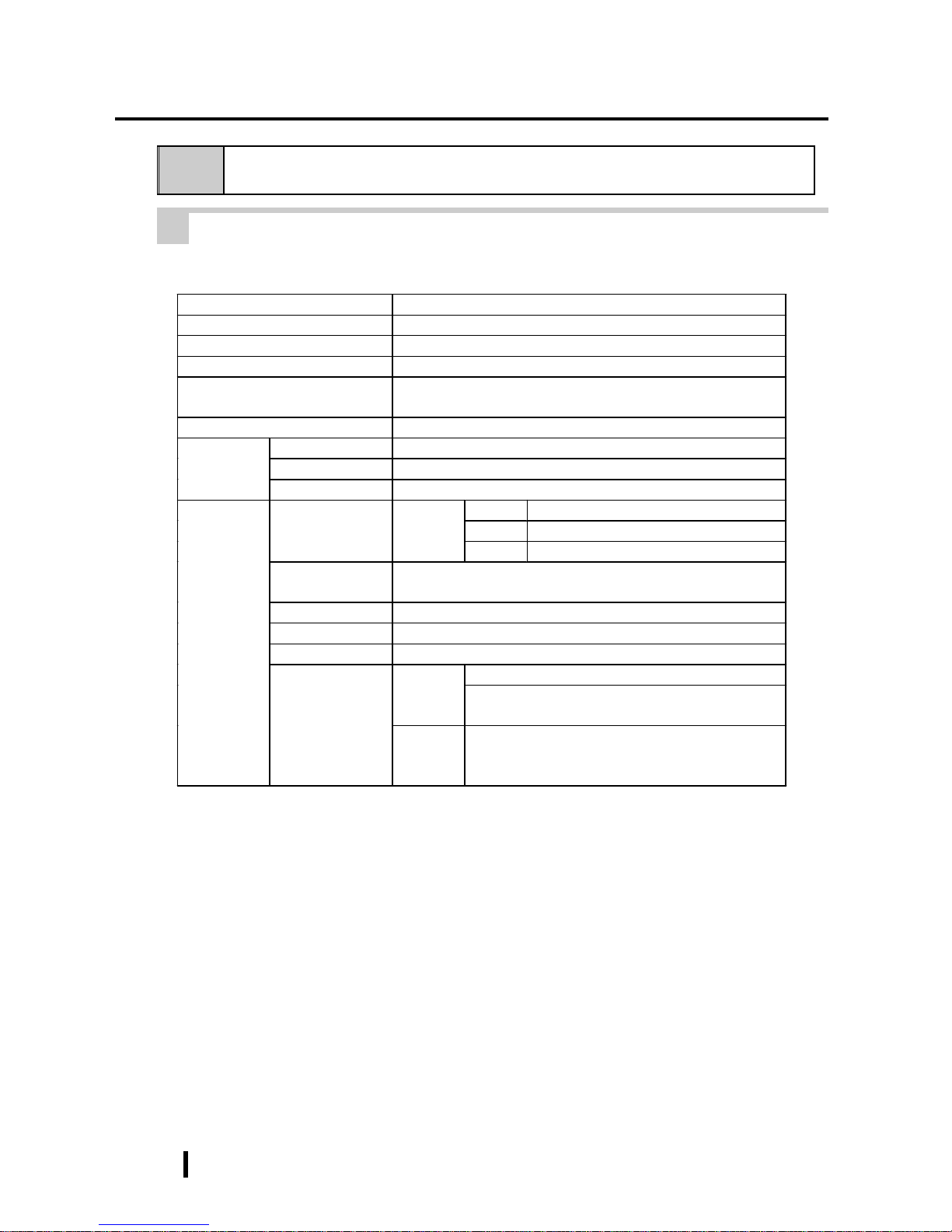
1 Performance Specifications
CPU
AMD-K6
®
-2 333 MHz (AMD Corporation)
DRAM (SDRAM DIMM)
Equipped with 64MB (2 DIMM sockets – max. of 128MB)
BIOS
AWARD PC/AT Compatible
Secondary Cache Memory
512KB (built-in)
Graphics
SVGA (800 x 600 dots)
VESA 16 colors/256 colors/32K colors/64K colors
Video Memory
2MB (SDRAM)
Type
Analog Resistant Film
Resolution
1024 x 1024
Touch
Panel
Interface
COM4 (uses Mouse Emulator)
COM1 D-Sub 9 pin (male)
COM2 D-Sub 9 pin (male)
Serial
RS-232C
(w/F IF O )
COM3 D-Sub 9 pin (male)
Printer
Complies with Centronics Standards (ECP/EPP equivalent)
D-sub 25 pin, female
Keyboard
PS/2 Interface (mini DIN 6 pin, female) side & front
Mouse
PS/2 Interface (mini DIN 6 pin, female) side
RAS
RAS Interface (D-sub 25 pin, male)
Side Access/ 2 modes/ 3.5” FD
FDD Unit
Front Access/ 2 modes/ 3.5” FD (Available for only
PL-6900T)
Front and
Rear
Interfaces
Disk I/F
E-IDE 2.5” HDD I/F
PL units eq uipped with a built-in HDD will u s e a 6 .0
or more GB unit.
2 - 5
PL-6900 Series User Manual
Specifications
Clock(RTC) accuracy
+180 seconds per month
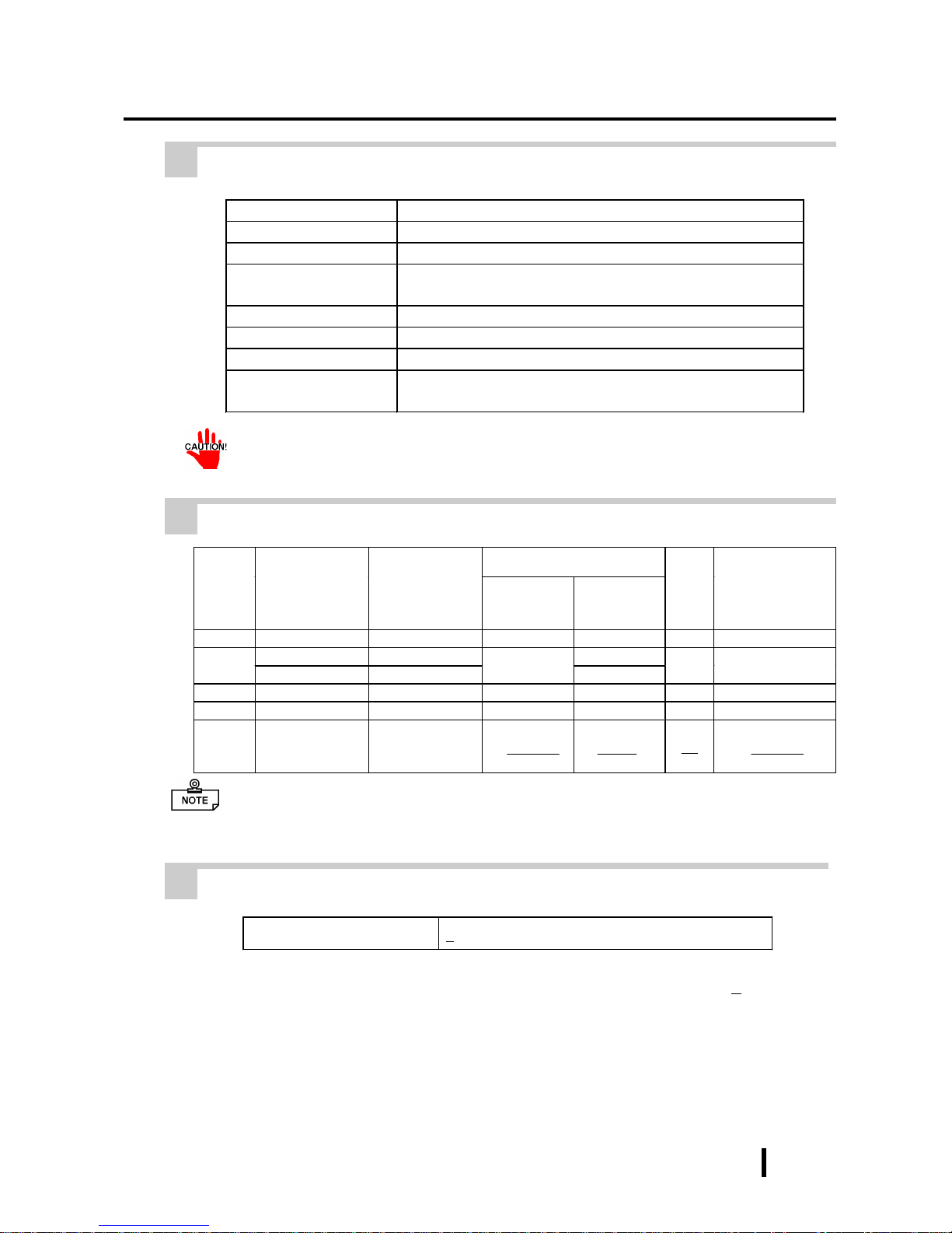
Board Si z e
PL-6900T
(4-slot type)
PL-6901T
(2-slot type)
Without the
Full-sized
cover
With the
Full-sized
cover
Slot
Pitch
Actual thickness
of Expansion
Board
1st slot
ISA ISA 163 x 122 mm 163 x 122 mm 20 mm Less than 13 mm
PCI PCI 250 x 122 mm
2nd slot
ISA ISA
250 x 122 mm
338 x 122 mm
25 mm Less than 18 mm
3rd slot
PCI/ISA None 250 x 122 mm 338 x 122 mm 25 mm Less than 18 mm
4th slot
ISA None 250 x 122 mm 338 x 122 mm 20 mm Less than 13 mm
Power
Supply
5V: 4A,
12V: 1A
(total for 4 slots)
5V: 2A,
12V: 0.5A
(total for 2 slots)
2 Display Functions
Display Type
TFT Color LCD
Pixel Density
800 x 600 pixels
Dot Pitch
0.3075 x 0.3075 mm
Effective Display
Area
W246.0 x H184.5 mm
Display Colors
260,000 colors
Contrast Control
Not Possible
Backlight
CFL (Replaceable)
Backlight’s Life span
More than 25,000 hours at an ambient temperature of 25
o
C. (Until
the backlight’s brightness dims to half of the original level.)
3 Expansion Slots
The PL’s backlight should be replaced by only an authorized repairman. For information about this service, please contact your nearest authorized distributor.
• For the 2nd and 3rd slots on the PL-6900T, and the 2nd slot on the PL-6901T,
either the PCI or the ISA type can be used.
4 Clock(RTC) Accuracy
The PL ’s built-in clock (RTC) may have a slight error . With the ambient temperature
mentioned in the specification with no power flow, the allowance is +180 seconds
per month, however, the allowance may vary and could be up to +300 seconds per
month depending on the ambient temperature difference or how old the unit is. If the
clock accuracy is essential for the system, you need to adjust the clock regularly.
2 - 6
PL-6900 Series User Manual
Specifications
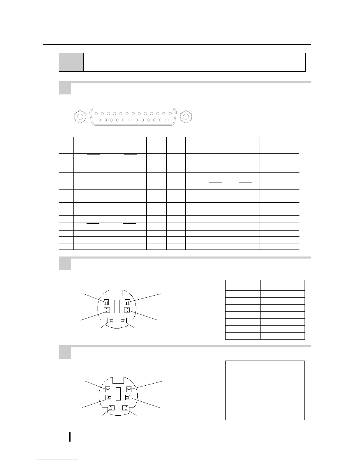
Pin No. Signal Name
1 Mouse DATA
2 NC
3 GND
4 +5V
5 Mouse CLK
6 NC
SHIELD GND
Pin No. Signal Name
1 KEY DATA
2 NC
3 GND
4 +5V
5 KEY CLK
6 NC
SHIELD GND
(The PL’ s front and side
connectors are the same)
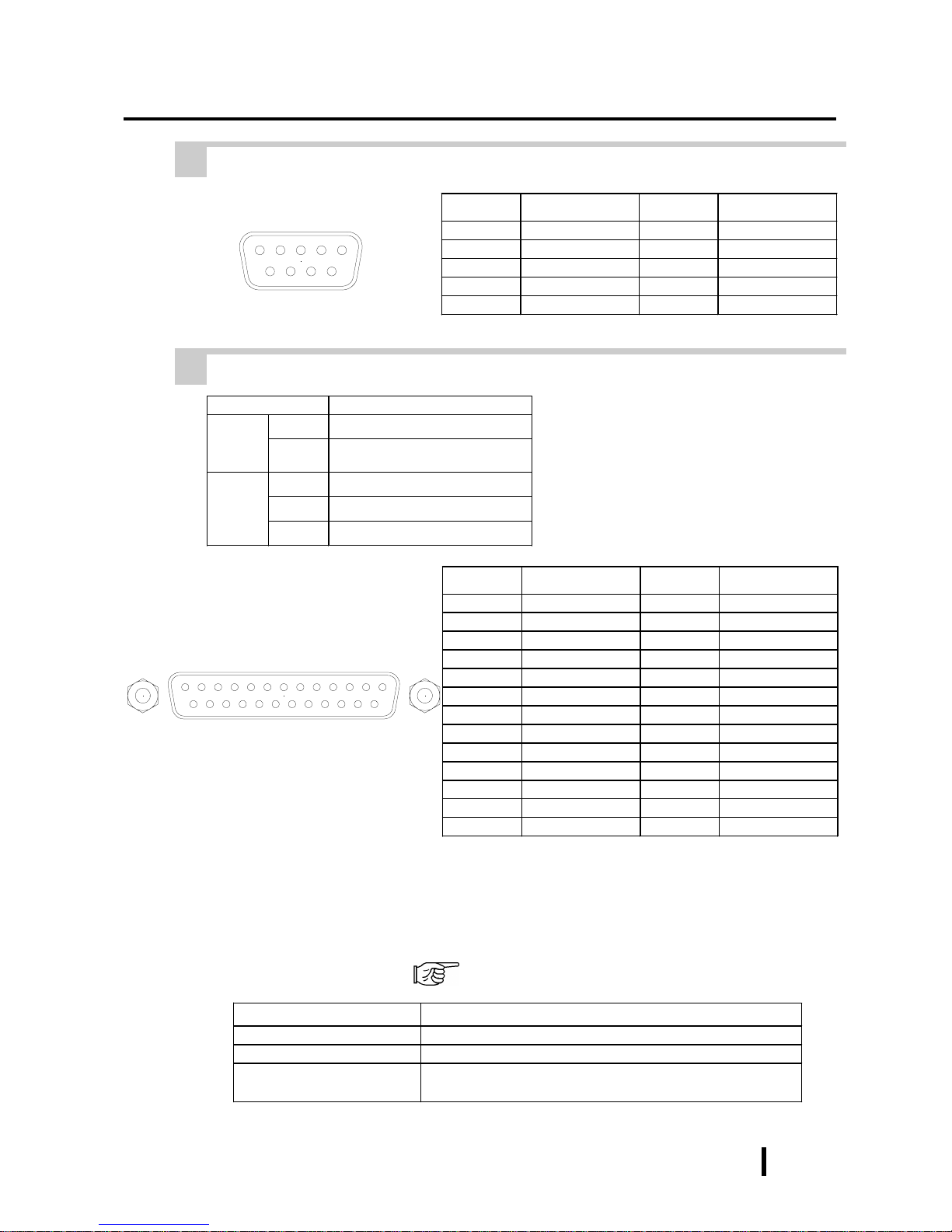
2-3 Interface Specifications
1 Printer Interface (LPT1)
2 Keyboard Interface
6
4
2
1
3
5
Mini - DIN 6 pin (Female)
3 Mouse Interface
6
4
2
1
3
5
Mini - DIN 6 pin (Female)
Pin
No.
SPP/ECP Mode
Signal Name
EPP Mo d e
Signal Name
Direction
Electrical
Specif.
Pin
No.
SPP/ECP Mode
Signal Name
EPP Mo d e
Signal Name
Direction
Electrical
Specif.
1 STRB WRITE
In/Output
O.D 14 AUTOFD DSTRB
In/Output
O.D
2 DATA0 DATA0
In/Output
O.D 15 ERROR ERROR Input TTL
3 DATA1 DATA1
In/Output
O.D 16 INIT INIT
In/Output
O.D
4 DATA2 DATA2
In/Output
O.D 17 SLCTIN ADSTRB
In/Output
O.D
5 DATA3 DATA3
In/Output
O.D 18 GND GND
6 DATA4 DATA4
In/Output
O.D 19 GND GND
7 DATA5 DATA5
In/Output
O.D 20 GND GND
8 DATA6 DATA6
In/Output
O.D 21 GND GND
9 DATA7 DATA7
In/Output
O.D 22 GND GND
10 ACKNLG ACKNLG Input TTL 23 GND GND
11 BUSY WAIT Input TTL 24 GND GND
12 PE PE Input TTL 2 5 GN D GND
13 SLCT SLCT Input TTL
D-sub 25 Pin (Female)
Screw Size: (4-40): Inch Type
13121110987654321
25 24 23 22 21 20 19 18 17 16 15 14
2 - 7
PL-6900 Series User Manual
Specifications
4 RS-232C Interface (COM1/COM2/COM3)
Pin No. Signal Name Pin No. Signal Name
1CD6DSR
2RXD7RTS
3TXD8CTS
4DTR9 RI
5GND
5 RAS Interface
Pin No. Signal Name Pin No. Signal Name
1 GND 14 GND
2 +5V 15 +5V
3 +12V 16 NC
4 NC 17 NC
5 RESET INPUT (+) 18 NC
6 DIN 0 (+) 19 NC
7 DOUT (-) 20 NC
8 DOUT (+) 21 LAMP OUT (-)
9 ALARM OUT (-) 22 LAMP OUT (+)
10 ALARM OUT (+) 23 NC
11 RESET INPUT (-) 24 DIN1 (-)
12 DIN 0 (-) 25 NC
13 DIN 1 (+)
Item Feature
Input
DIN 0,1 Digital Input Port (2 points)
RESET
Hardware can be reset via external
reset signal.
Output
DOUT Digital output port (1 point)
Alarm Alarm signal output port (1 point)
Lamp Alarm lamp connection port (1 point)
Dsub 9 pin (Male)
Screw Size: (4-40): Inch Type
9
87
6
5
4321
LED Status
Gr een,Lights Continuously Nor mal O per ation
Or ange , Light s Cont inuou sly System Monit or Alarm has occur r ed
Or ange , Blink ing
When the Mirror Disk unit is installed, indicate s that a har d
disk error has det ec ted
Power Lamp LED Error Display
The Power Lamp LED indicates when the RAS feature has detected an error, due to a
PL operation or environment related problem.
T o use this feature, you need to install the RAS system monitor feature from the PL’s
additional floppy disk. 6-1 Floppy Disk File List
Screw Size: (4-40): Inch Type
D-Sub 25 pin (Male)
1 2 3 4 5 6 7 8 9 10111213
14 15 16 17 18 19 20 21 22 23 24 25

2 - 8
PL-6900 Series User Manual
Specifications
(Interfa ce Circui t )
(Connection Example)
Cable
R
PC357
Dsub 25pin
connector
N3904
DOUT(-)pin 7
Alarm Output(-)pin 9
Lamp Output(-)pin 21
DOUT(+)pin 8
Alarm Output(+)pin 10
Lamp Output(+)pin 22
+5V
4.7k
Ω
Output Port
(Interfa ce Circu i t )
(Connection Example)
Cable
DC12 to
24V
External
Power
Reset Input(+)pin 5
DIN0(+)pin 6
DIN1(+)pin 13
(12 to 24V)
R
PC357
Reset Input(-)pin 11
DIN0(-)pin 12
DIN1(-)pin 24
D-sub 25 pin
Connector
+5V
3.3k
Ω
1/4W
Input Port
Input Port (Dual use of DIN, Remote Set Input Port)
- External Power : DC12V to 24V connection possible
- Input Hold : Hold Diode
- Isolation : Used (Photo isolation)
Output Port (DOUT, Alarm Output, Lamp Output Port)
- Output Spec. : DC 24V 100mA (MAX)
- Isolation : Used (Photo isolation)

2 - 9
PL-6900 Series User Manual
Specifications
D E
F
G
H
C
2-4 PL External Features
A B
A:Display Area
Display output area. The built-in SVGA controller supports PC compatible architecture.
B:T ouch Panel
This high-resolution analog touch panel allows you
to configure a keyboard-less system.
C:Power Lamp LED
The status of the lamp changes according to the
alarm type detected by the RAS feature.
2-3-5 RAS Interface
D:Front Maintenance Cover
Open this cover to connect the optional FDD unit.
E:IrDA
Infra-red signals can be sent and received by this unit.
F:Keyboard Connector
A PS/2 compatible keyboard is connected here.
G:Hardware Reset Switch
H:Front Mount FDD Slot
Slot for installing the FDD unit (PL-FD210).
(only PL-6900T)
I:RS-232C Connector (COM1)
J:RS-232C Connector (COM2)
K:RS-232C Connector (COM3)
These RS-232C interfaces (D-sub 9 pin male connectors), allow communication with other computers and connection to peripheral devices.
L:Printer Connector (LPT1)
Centronics standard interface (D-sub 25 pin female
connector), which connects a parallel device, such
as a printer (supports ECP/EPP).
M:RAS Connector
Interface for DIN, DOUT , Watchdog, and Remote
Reset. (D-sub 25 pin male connector)
N:Power T erminals
The PL ’s AC100V/240V power cord terminals are
connected here.
O:IDE I/F Cover
To connect the optional CD-ROM drive unit (PLDK200) and Mirror Disk Unit(PL-MD200-HU01),
remove this cover and use this connector.
MIJ KL
O N
PL-6901T(2Slot)
MIJ KL
ONH
PL-6900T(4Slot)
<
I
nside the front maintenance cover>

2 - 10
PL-6900 Series User Manual
Specifications
P:Keyboard Connector
A PS/2 compatible keyboard can be connected
here.
Q:Mouse Connector
A PS/2 compatible mouse can be connected here.
R:Side Mount FDD Slot
Houses the FDD unit.
S:Expansion Slots (2)
T:HDD/FFD Expansion Unit Slot
Houses an additional HDD unit, or FFD unit.
U:Half Cover
When an optional DIM module or expansion board
is used here, this cover is removed.
V:Power Switch
Use this switch to turn the PL’s power ON or OFF.
W:Rear Maintenance Cover
Remove this cover to install the optional DIM
module, or an expansion board.
• When attaching peripheral units to the PL, be sure the PL’s power cord is
disconnected from the main power supply.
• To avoid an electrical shock, be sure to disconnect the PL’s power cord from
the power supply before connecting the cord’s power terminals or any peripheral devices to the PL.
4-3-1 Connecting the Power Cord
U
V
W
S
R
T
P
Q
PL-6901T(2Slot)
PL-6901T(2Slot)
PL-6901T(2Slot)

2 - 11
PL-6900 Series User Manual
Specifications
2-5 PL Dimensions
1 PL- 6900T General Dimensions
(Unit: mm - excluding projections)
330
170
13
271
346
287
Side View
Top View
Rear View
Front View

2 - 12
PL-6900 Series User Manual
Specifications
330
Side View
Top View
Rear View
Front View
346
287
123
13
271
2 PL- 6901T General Dimensions
(Unit: mm - excluding projections)

2 - 13
PL-6900 Series User Manual
Specifications
3 Full Sized Cover Attachment Dimensions
Top View
(Unit: mm)
(PL-6901T)
• The above figure’s dimensions are the same for the 2 and 4 slot units.
• When using a full-sized board and the PL’s full-sized cover (PL-FC200/PLFC210), be sure that the PL is mounted in its attachment panel/cabinet before
starting this work. Due to size differences, the full-sized cover or a full sized
expansion board cannot be attached first and then the PL installed into a
panel.
• When using a full-sized expansion board, be sure to check its dimensions and
shape, since they will affect the board’s environment specifications, such as
for vibration, etc.
310
65
10

2 - 14
PL-6900 Series User Manual
Specifications
272.0
+0.5
-0
331.0
+0.5
-0
less than
4-R2
• Be sure the thickness of the panel is from 1.6 to 10 mm.
• All panel surfaces used should be strengthened. Especially, if high levels of
vibration are expected and the PL’s installation surface (i.e. an operation
panel’s door, etc.) can move (i.e.open or close) due consideration should be
given to the PL’s weight.
• To insure that the PL’s water resistance is maintained, be sure to install the PL
into a panel that is flat and free of scratches or dents.
• Be sure all installation tolerances are maintained to prevent the unit from
falling out of its installation panel.
4 Installation Slot Dimensions
(Unit: mm)

3 - 1
PL-6900 Series User Manual
Installing Optional Units and Expansion Boards
Chapter
3
3-1 Installing Options and Expansion Boards
Installing Optional Units
and Expansion Boards
The User can install a variety of optional units and expansion boards made by Digital in the
PL, as well as a number of commercially available ISA-bus compatible boards. This chapter describes both the products that can be installed in the PL and how to install them.
WARNING
Use a screw driver to loosen or tighten the screws. Be careful not to over-tighten
any screws, since it may damage the equipment.
Be careful when removing or inserting any screws inside the body of the PL.
3-1
Installing Options and Expansion Boards
T o avoid electric hazards, be sure to turn the PL’s power OFF before installing
any optional units or expansion boards.
The following explanation pages describe the installation procedures for the PL’s
DIM module (PL-EM220/PL-EM230), FDD unit (PL-FD200/PL-FD210), HDD
unit (PL-HD220), expansion boards, and the CD-ROM drive unit (PL-DK200).
For information about the installation of other option units, please refer to those
unit’s individual [Operation Instructions].

3 - 2
PL-6900 Series User Manual
Installing Optional Units and Expansion Boards
2) Pivot the half cover open and lift
up slightly to free the guide tabs.
Next, remove the half-cover.
3) Remove the rear maintenance cover .
Half Cover
Rear Maintenance
Cover
1) Unscrew the four attachment screws
used to hold the rear maintenance
cover and half-cover in place.
Remove the half cover, and
then the rear maintenance
cover.
1 Removing the rear maintenance cover
Handle the rear maintenance cover with care, since it is made of aluminum and
is easily bent.
PL-6901T (2 slot type)
Guide Tabs
Half Cover

3 - 3
PL-6900 Series User Manual
Installing Optional Units and Expansion Boards
Guide Tabs
PL-6900T (4 slot type)
Half Cover
Rear Maintenance
Cover
Half Cover
2) Remove the rear maintenance cover.
1) Unscrew the attachment screws used
to hold the rear maintenance
cover(4) and half cover(1) in place.
3) Pivot the half cover open and lift
up slightly to free the guide tabs.
Next, remove the half cover.
Remove the rear maintenance cover, and then the
half cover.

3 - 4
PL-6900 Series User Manual
Installing Optional Units and Expansion Boards
Foolproof
Positioning grooves
3) Adjust the foolproof positioning
grooves so that they align with the
foolproof positioning pins.
Foolproof
Positioning pins
4) Insert the DIM module into the
DIM module socket.
2) Install the DIM module for expansion on the empty socket.
2 Installing the DIM Module
(
PL-EM220 / PL-EM230
)
The PL comes with a single, 64MB DIM module pre-installed. There is one more
empty socket that can be used and the procedures that follow describe how to install
a second DIM module in that socket.
Since DIM module sockets are easy to break, be sure to install the DIM module
very carefully .
1) Replace the rear maintenance
cover and the half cover.
3-1-1 Removing the rear maintenance cover
Built-in DIM Module
Empty Socket

3 - 5
PL-6900 Series User Manual
Installing Optional Units and Expansion Boards
5) Push the DIM module down until
the side stoppers lock.
6) Replace the rear maintenance
cover and the half cover and secure
them in place with the attachment
screws.
To Remove the DIM Module
When removing the module from the socket, press down on the socket’s ejector
tabs to release the module.
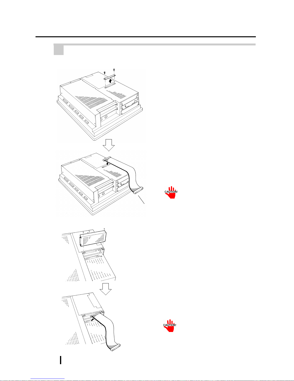
3 Installing the FDD Unit (PL-FD200)
1) Remove the two(2) attachment
screws from the lowermost Expansion Slot Cover, and remove the
cover.
2) Insert the FDD unit so that its guide
grooves fit the chassis guide ways.
Push the unit in until its rear connector is connected securely.
3) Fix the unit in place with its two(2)
attachment screws.
(PL-6901T)

3 - 6
PL-6900 Series User Manual
Installing Optional Units and Expansion Boards
4 Installing the FDD Unit (PL-FD210)
3) Unscrew the two(2) attachment
screws from the PL-FD210’s Blank
Panel, and remove the blank panel.
1) Open the front maintenance cover
and remove the FDD’s blank (filler)
panel.
2) Close the front maintenance cover.
FDD’s blank (filler) panel
PL-FD210
Blank Panel
(Rear Face)
4) Loosen the FDD unit chassis two (2)
upper adjustment screws, and remove the unit’s two (2) lower set
screws to allow the FDD unit to
slide forward.
Lower Set
Screws
Upper Adjustment
Screws

3 - 7
PL-6900 Series User Manual
Installing Optional Units and Expansion Boards
5) Push on either end of the FDD unit
to compress the unit to its shortest
length. Then, re-tighten the two attachment screws to secure the unit
in place.
7) Fix the unit in place with its two(2)
attachment screws.
8) Last, replace the Blank Panel (removed in step 3).
6) Insert the FDD unit so that its guide
grooves align with the chassis
holder guideways. Push the unit
into the PL holder until its connector (middle of unit) is connected
securely.
When installing the PL-FD210, insert it slowly into the PL’s installation opening and be sure it is securely attached.
Push up

3 - 8
PL-6900 Series User Manual
Installing Optional Units and Expansion Boards
5 Removing/ Installing the HDD Unit (PL-HD220)
Since the PL-HD220 units are
precision instruments, be sure
not to jar or shake them unnecessarily.
1) Remove the two(2) attachment
screws from the middle Expansion
Slot Cover.
3) Insert the HDD unit you selected
inside the guideways of the PL and
push it in until its rear connector
is securely connected.
4) Fix the unit in place with its two(2)
attachment screws.
The following procedure is applicable also to the FFD unit(PL-FF200) and
HDD (IDE) expansion slot.
(PL-6901T)
HDD/FFD
Expansion Slot
2) Grasp the HDD unit’s handle and
pull the unit slowly out of the PL.
Be sure you do not damage the unit.

3 - 9
PL-6900 Series User Manual
Installing Optional Units and Expansion Boards
6 Installing an Expansion Board
1) Remove the PL’s rear maintenance
cover and the half cover.
3-1-1 Removing the rear maintenance cover
2) Unscrew the attachment screw fr om
the expansion slot cover, and remove the cover.
3) Remove the duster cover.
4) Insert the expansion board into the
expansion slot.
5) Fix the expansion board’s metal positioning strip in place with its attachment screw.
6) Last, secure the rear maintenance
and half covers in place with their
attachment screws.
3 - 10
PL-6900 Series User Manual
Installing Optional Units and Expansion Boards
1) Unscrew the two(2) attachment
screws on the IDE I/F cover, then
remove the cover.
2) Connect the CD-ROM unit’s cable
to the IDE I/F.
7 Connecting the CD-ROM Unit (PL-DK200)
PL-6901T (2 slot type)
Connected to the
CD-ROM
PL-6900T (4 slot type)
1) Unscrew the two(2) attachment
screws on the IDE I/F cover, and
remove the cover.
2) Connect the CD-ROM unit’s cable
to the IDE I/F.
Be sure that the cable is securely connected before turning ON the power switch.
Be sure that the cable is securely connected before turning ON the power switch.

3 - 11
PL-6900 Series User Manual
Installing Optional Units and Expansion Boards
The PL can be operated without the bottom face cooling fan unit. The user should,
however, be aware that doing so (i.e. removing the fan unit) will cause the PL’s
ambient temperature to rise. See “2-1-2 Environment Specifications”
Cooling
Filter Cover
8 Removing the Cooling Fan Unit
1) Remove the attachment screw on
the cooling filter cover , and r emove
the cover.
Filter
2) Remove the filter.
3) Remove the two(2) attachment
screws on the fan unit, and take out
the fan unit.
PL-6901T (2 slot type)

3 - 12
PL-6900 Series User Manual
Installing Optional Units and Expansion Boards
4) Unplug the power cable connector
from the cooling fan unit.
5) Unscrew the fan’s two(2) attachment screws, then remove the fan
unit from its metal attachment
plate.
6) Reattach the metal plate and the filter cover to the PL.
1) Remove the cooling filter cover’s
attachment screw.
2) Remove the cooling filter cover
from the fan unit, and then remove
the fan unit’s two(2) attachment
screws.
Metal plate
Fan Unit
Cooling
Filter cover
PL-6900T (4 slot type)

3 - 13
PL-6900 Series User Manual
Installing Optional Units and Expansion Boards
5) Unscrew the two(2) fan unit’s attachment screws and then remove
the fan unit from the metal plate
holding the fan unit.
3) Remove the fan unit from the PL.
4) Disconnect the fan unit’s power
cable connector from the PL.
6) Re-attach the metal plate and the
cooling filter cover to the PL.
Power Cable Connector
Metal Plate
Fan Unit

3 - 14
PL-6900 Series User Manual
Installing Optional Units and Expansion Boards
MEMO

4- 1
PL-6900 Series User Manual
Installation and Wiring
Chapter
4
4-1 Installation Cautions
4-2 Installing the PL
4-3 Wiring the PL
Installation and Wiring
This chapter explains how to install and wire the PL-6900 Series, as well as the cautions required both before and during installation.
Also, be sure that the panel’s viewing angle
is tilted no more than 30 degrees from parallel to the operator (i.e. directly in front).
2) Installation Positioning Cautions
Be sure to install the panel in an upright (vertical) position.
OK
No more than 30 degrees of tilt
4-1 Installation Cautions
Ambi ent Operati ng Temperature
W/ PL Fan
5
o
C to 50oC
W/OUT PL Fan
5
o
C to 40oC
1) Temperature Related Cautions
• The PL should be installed in a vertical position, and forced air cooling should be used, instead of natural air circulation.
• To prevent a machine breakdown, be sure to
use the PL within the allowable temperature
range as below-listed. Please check “Ambient Operating Temperature” in the position
drawn on the left. (“Ambient Operating T emperature” indicates both the panel interior and
panel face temperature.)
100mm
30mm
Panel Face Panel Interior
100mm
30mm

4 - 2
PL-6900 Series User Manual
Installation and Wiring
PL Unit
Shock
Resistance
When using the HDD Up to 4.9m/s2
When using the FDD Up to 9.8m/s2
When using no drives Up to 19.6m/s2
3) Vibration Related Cautions
Be sure to protect the PL from excessive vibration or jolting. These kinds of shocks can
cause the PL to malfunction.
• Be sure not to move the PL unit
while the HDD is starting up. This
can lead to a machine breakdown
(Even a slight movement of the PL
should not be performed).
• When using a fan to cool the PL unit,
be sure that the fan does not point
directly at any of the PL ’s disk drive
units.

4 - 3
PL-6900 Series User Manual
Installation and Wiring
1 Installation Procedures
Follow the steps given below when installing the PL.
4-2 Installing the PL
Attaching the Moisture Resistant Gasket
PL Rear Face
Gasket
Even if the your PL’s Moisture Resistant Gasket is not needed to prevent water
from entering the unit, the gasket also acts as a vibration absorber and should
always be attached. To install it, place the PL face down on a soft surface and
attach the gasket to the rear side of the display face, in the plastic bezel’s groove
(see picture below).
Before mounting the PL into a cabinet or panel, check that the moisture
resistant gasket is attached to the unit.
Create a hole for mounting the PL, like that pictured here. Two additional items,
the moisture resistant gasket and the mounting brackets are also required when
installing the PL. 2-5 PL Dimensions
Create an Installation Slot
> <
1.6 - 10.0 mm
> <
• To obtain the maximum degree of moisture resistance, be sure to mount the PL on a
smooth, flat surface.
• The panel itself can be from 1.6 to 10.0 mm thick.
Panel
Mounting hole
Strengthening may be requir ed for the panel. Be sure to consider the weight
of the PL when designing the panel.

4 - 4
PL-6900 Series User Manual
Installation and Wiring
• Avoid placing the PL next to other devices that might cause overheating.
• Avoid using the PL where the ambient temperature will exceed 40°C (50°C when
using a cooling fan).
• Keep the PL away from arc-generating devices such as magnetic switches and nonfuse breakers.
• Avoid using the PL in environments where corrosive gases are present.
• Be sure that the panel’ s viewing angle is tilted no more than 30 degrees from parallel
to the operator (i.e. operator is directly in front).
Must be 30 degrees or less
OK
OKOK
Side panel
Mounting panel
Insert the PL into the installation slot
Side View Rear View
50mm
50mm
50mm
50mm
50mm
50mm
50mm
PL Viewing Angle
To enhance the PL’s maintainability, operability and ventilation, allow at least 50mm
or more clearance between the PL and any other objects. (The clearance must be
large enough to allow you to insert or remove expansion boards and to attach
connectors.)
Note:
Be sure the installation panel’s actual measurements are the same as those
given here, otherwise the PL may slip or fall out of the panel.

4 - 5
PL-6900 Series User Manual
Installation and Wiring
Attach and Secure the Rear Attachment Brackets
1) Locate the PL’s eight (8) attachment holes, located on the top, bottom, and sides
of the PL.
2) Insert each bracket into its attachment hole.
3) Insert each mounting bracket into an attachment hole, and slide the bracket backwards until it stops.
4) Use a screwdriver to tighten the bracket’s adjustment screw. To ensure a high
degree of moisture resistance, the torque should be 0.5N•m.
Attachment
hole
Excessive torque may damage
the panel or bracket.
Attachment hole
Top Face
Left Side
Front
panel
of PL
Rear
panel
of PL
Mounting bracket

4 - 6
PL-6900 Series User Manual
Installation and Wiring
WARNING
4-3 Wiring the PL
1 Connecting the Power Cord
T o pr event electric shocks, be sure to turn the PL OFF before connecting the power cord.
To avoid the dangers of fire, electric hazards and equipment damage, be sure to use
only the specified power supply voltage when operating the PL.
Use the following steps when connecting the power cord to the PL’s power terminals.
(Rear of PL)
L
N
FG
Power Input Terminals
Connecting these two terminals provides 100V to 240V
AC power.
L= live and N= Neutral
This terminal is connected
to the PL ’s frame (chassis).
(screw size: M3)
Power T erminals
Power Switch
PL-6901T (2-Slot Unit)
1) Confirm that the power switch is
turned OFF. Then, remove the
power terminal’s transparent plastic cover.
POWER
Screws
Transparent Cover
FG
L
N
I
o
I:ON
o:OFF

4 - 7
PL-6900 Series User Manual
Installation and Wiring
2) Loosen and remove the middle three(3)
screws from the terminal strip. Align the
crimp terminals with each screw hole,
and tighten the screws.
• Crimp Terminal Types :
V1.25-3, by J.S.T. or equivalent (JIS
standard part number : RAV1.25-3)
• Crimp terminals must be the same
as shown below.
3) Reattach the terminal strip’s transparent cover with the attachment screws.
^
^
^
φφ
φφ
φ
3.2 mm or larger
Max. 6.0 mm
• The colors in the figure above are
for the cable which came with
the PL.
• This power cable is designed
only for AC100/115V use. Be
sure to use a different cable
when using other than AC100/
115V power.
FG
L
N
FG
L
N
Black
White
Green/Y ellow
Transparent
Cover
Attachment
Screws

4 - 8
PL-6900 Series User Manual
Installation and Wiring
• If voltage fluctuations are expected to vary beyond the specified range, connect a constant
voltage transformer.
For information about the specified
voltage, refer to “2-1 General
Specifications”
• Use a low-noise power supply both between the lines and between the PL and its
ground. If there is still excess noise, connect an insulating transformer (noise-prevention type) .
• Wire the power cords of the PL, I/O devices, and power supply devices separately .
• To improve noise immunity , it is recommended
to attach a ferrite core to the power cord.
• Isolate the main circuit (high voltage, large
current) line, I/O signal lines, and power cord,
and do not bind or group them together.
• To prevent damage from lightning, connect a
lightning surge absorber .
Constant
voltage
transformer
Twisted-pair
cable
PL
FG
Insulating
transformer
Twisted-pair
cable
PL
FG
Main power
source
PL power
source
T1
T2
I/O power
source
PL
I/O
device
I/O
device
Main circuit
power source
Power
device
AC 200V
Twisted-pair
cable
PL
FG
Lightning surge absorber
AC
E1
E2
• Gr ound the lightning surge absorber
(E1) and the PL (E2) separately.
• Select a lightning surge absorber
which will not exceed the allowable
circuit voltage, even when the
voltage rises to the maximum.
Be sure any constant or insulating
transformer used has a capacity of
200VA or more.
AC100V
PL power
source
I/O power
source
PL
I/O
device
Main power
source
2 Power Supply Cautions
When connecting the PL unit’s AC power terminals, please be aware of the following:

4 - 9
PL-6900 Series User Manual
Installation and Wiring
• The grounding point must be as close to
the PL as possible, and the grounding
wires must be as short as possible. If the
wires must be long, use thick, insulated
wires and run them through conduits.
(a) Dedicated Ground
*1
• Set up a dedicated ground when using
the rear panel’s FG terminal.
(b) Shared Ground - allowed
*1
• If a dedicated ground is not possible, use
a shared ground, as shown in figure (b).
(c) Shared ground - not allowed
3 Grounding Cautions
PL
PL
Other
device
Other
device
4 Cautions When Connecting I/O Signal Lines
• I/O signal lines must be wired separately from the power circuit cable.
If the power circuit cable needs to be wired together with the input/output
(I/O) signal lines for any reason, use shielded cables and ground one end of
the shield to the PL’s FG terminal.
• To improve noise immunity, it is recommended to attach a ferrite core to the
power cord.
Other
device
PL
*1 Use a grounding resistance of 100Ω or less, and a 2mm2 or thicker wire, or your
country’s applicable standard. For details, contact your local PL distributor.
.

4 - 10
PL-6900 Series User Manual
Installation and Wiring
MEMO

System Setup
5 - 1
PL-6900 Series User Manual
1) Connect a keyboard to the PL.
2) Turn the PL's power ON.
3) After the message "Press <DEL> to Enter SETUP" appears, press the [DEL]
key until the following screen appears.
The following settings are those pre-set at the factory.
Normally , use only the factory (default) settings.
Chapter
5
5-1 Setup Procedures
5-2 System Parameters
This chapter explains how to enter a PL-6900 Series unit's system settings, as well as the
cautions required both before and during set up.
System Setup
5-1 Setup Procedures
KEYBOARD ACTION KEYS
Provides a summary of the keyboard keys used to carry out the set up.
SYSTEM SETTING SELECTION AREA
Each of the titles (areas) listed here contains system setting items.
STANDARD CMOS SETUP
BIOS FEATURES SETUP
CHIPSET FEATURES SETUP
POWER MANAGEMENT SETUP
PNP/PCI CONFIGURATION
LOAD BIOS DEFAULTS
LOAD SETUP DEFAULTS
SYSTEM MONITOR UTILITY
INTEGRATED PERIPHERALS
SUPERVISOR PASSWORD
USER PASSWORD
IDE HDD AUTO DETECTION
SAVE & EXIT SETUP
EXIT WITHOUT SAVING
ROM PCI/ISA BIOS (2A5LEU1C)
CMOS SETUP UTILITY
AWARD SOFTWARE, INC.
ESC : Quit : Select Item
F10 : Save & Exit Setup (Shift)F2 : Change Color
Time,Date,Hard Disk Type •••
4) Use the arrow keys to move the cursor to the desired selection.

System Setup
5 - 2
PL-6900 Series User Manual
System Parameters
Date/Time
This data sets the PL's internal time and date.
Hours :00 - 23
Minutes :00 - 59
Seconds :00 - 59
Drive C
This data sets the IDE hard disk's parameters. When this setting is set
to [AUTO], the hard disk's parameters are automatically read in. Also,
if the "IDE HDD AUTO DETECTION" is in use, the value entered
there is automatically set. The three options are [User],[Auto], and
[None]. The [Auto] setting is factory set and recommended for most
users.
Drive D
The three options are [User],[None]and [Auto].
Drive A
This setting determines the format used by the PL's internal floppy disk
drive. The[1.44M - 3.5in] selection is factory set and recommended
for most users. The other available settings are [720K - 3.5in], [1.2M
- 5.25in], [360K - 5.25in], [2.88M - 3.5in.], and [None].
Video
The selections for the screen (video) mode. The [EGA/VGA] selection
is factory set and recommended for most users. The other available
settings are [CGA40], [CGA80] and [Mono].
Selecting the STANDARD CMOS SETUP menu item produces the following screen.
5-2
1 ST ANDARD CMOS SETUP
Date (mm:dd:yy): Thu,Jul 2 1998
Time (hh:mm:ss): 14 : 50 : 3
CYLS. HEADS PRECOMP LANDZONE SECT0RS MODE
Drive C :Auto( 0Mb) 0 0 0 0 0 AUTO
Drive D :Auto( 0Mb) 0 0 0 0 0 AUTO
Drive A :1.44M,3.5 in.
Base Memory : 640K
Extended Memory : 645612K
Other Memory : 384K
Total Memory : 66536K
ROM PCI/ISA BIOS(2A5LEU1C)
STANDARD CMOS SETUP
AWARD SOFTWARE, INC.
ESC : Quit : Select Item PU/PD/+/-:Modify
F1 : Help (Shift)F2 : Change Color
Video : EGA/VGA
VGA Text Mode : Normal
VGA Graphics Mode : Normal
Halt On : All, But Disk/Key

System Setup
5 - 3
PL-6900 Series User Manual
VGA Text Mode
This mode changes the screen (video) mode from [Normal](VGA mode)
to [Expansion](800×600). The[Normal] selection is factory set and
recommended for most users.
VGA Graphics Mode
This mode changes the screen (Graphics) mode from [Normal](VGA
mode) to [Expansion](800×600). The[Normal] selection is factory set
and recommended for most users.
Halt On
Designates the type of processing that will be performed when an error
occurs during the Initial Start-Up's Self Test. The [All But Disk /Key]
selection is factory set and recommended for most users.
[All Errors] : Displays all errors and stops the unit.
[No Errors] : Displays all errors and does not stop the unit.
[All,But Keyboard] : Displays all errors, except for those related to
the keyboard, and stops the unit. If the User has
no keyboard connected, please use this setting.
[All,But Diskette] : Displays all errors, except for those related to
the disk drive (FDD), and stops the unit.
[All,But Disk/Key] : Displays all errors, except for those related to the disk
drive (FDD) and keyboard, and then stops the unit.

System Setup
5 - 4
PL-6900 Series User Manual
Selecting the BIOS FEATURES SETUP menu item calls up the following
screen.
2 BIOS FEA TURES SETUP
Virus Warning
CPU Internal Cache
External Cache
Quick Power On Self Test
Boot Sequence
Boot Up Floppy Seek
Boot Up NumLock Status
Boot Up System Speed
Gate A20 Option
Memory Parity/ECC Check
Typematic Rate Setting
Typematic Rate(Chars/Sec)
Typematic Delay (Msec)
Security Option
PCI/VGA Palette Snoop
OS Select For DRAM > 64MB
Video BIOS Shadow : Enabled
C8000-CBFFF Shadow : Disabled
CC000-CFFFF Shadow : Disabled
D0000-D3FFF Shadow : Disabled
D4000-D7FFF Shadow : Disabled
D8000-DBFFF Shadow : Disabled
DC000-DFFFF Shadow : Disabled
:Disabled
:Enabled
:Enabled
:Enabled
:A,C,SCSI
:Enabled
:On
:High
:Fast
:Enabled
:Disabled
:6
:250
:Setup
:Disabled
:Non-OS2
ROM PCI/ISA BIOS(2A5LEU1C)
BIOS FEATURES SETUP
AWARD SOFTWARE, INC.
ESC :Quit : Select Item
F1 : Help PU/PD/+/- : Modify
F5 : Old Values (Shift)F2 : Color
F6 : Load BIOS Defaults
F7 : Load Setup Defaults
Virus Warning
Designates whether a warning message appears when an error
occurs during a write to the Hard Disk's Boot Sector. The two
selections are[Disabled] and [Enabled]. The [Disabled] selection is
factory set and recommended for most users.
CPU Internal Cache
Designates if the CPU's Internal Cache Memory is used or not. The
two selections available are [Disabled] and [Enabled]. The
[Enabled] selection is factory set and recommended for most users.
External Cache
Designates if the CPU's External Cache Memory (L2) is used or
not. The two selections available are [Disabled] and [Enabled]. The
[Enabled] selection is factory set and recommended for most users.
Quick Power On Self Test
Designates if a simplified Self Test is used after the power is
turned ON. The two selections available are [Disabled] and
[Enabled]. The [Enabled] selection is factory set and recommended
for most users.
Boot Sequence
Designates the drive order used by the OS during start up.
The [A,C,SCSI] is factory set and recommended for most users.
The other available settings are [A,C,SCSI], [C,A,SCSI],
[C,CDROM,A], [CDROM,C,A], [D,A,SCSI], [SCSI, A,C,],
[SCSI,C,A] and [C Only].

System Setup
5 - 5
PL-6900 Series User Manual
Boot Up Floppy Seek
Designates if the floppy disk drive installation check is used or not. The
available selections are [Disabled] and [Enabled]. [Enabled] is factory
set and recommended for most users.
Boot Up NumLock Status
Designates the condition of the NumLock key at startup. The two
selections are either [On] or [Off]. The [On] selection is factory set and
recommended for most users.
Boot Up System Speed
Designates the speed of CPU. [High] is factory set and recommended for
most users. The other available selection is [Low].
Gate A20 Option
The two selections available are [Fast] and [Normal]. When [Normal] is
selected, Keyboard Control is used for Gate A20 control. When [Fast] is
selected, the Chipset is used. The [Fast] selection is factory set and
recommended for most users.
Memory Parity / ECC Check
Designates if a Parity Check is used for Parity Memory. The two
selections available are [Disabled] and [Enabled]. The [Enabled]
selection is factory set and recommended for most users.
Typematic Rate Setting
Designates the repeat mode for characters on the keyboard. The
selections [Disabled] and [Enabled] are available. [Disabled] is factory
set and recommended for most users.
Typematic Rate (Chars/Sec)
When [Enabled] is selected on [Typematic Rate Setting], it designates
the actual rate (the number of repeating characters per second).
[6],[8],[10],[12],[15], [20],[24] and [30] are the available selections.[6]
is factory set.
Typematic Delay (Msec)
When [Enabled] is selected on [Typematic Rate Setting], it designates
the time until repetition of a character starts. The unit is mili-second
(msec). The available selections are [250],[500],[750]and [1000].
[250] is factory set.
Security Option
Designates the location of the Password Entry. The selection [Setup] is
for BIOS setup,and the other selection [System] is for both BIOS setup
and Start up.When the [Supervisor Password] or [User Password] has
not been designated, this setting is disabled. [Setup] is factory set and
recommended for most users.
PCI/VGA Palette Snoop
When the PCI/VGA and the MPEG ISA/VESA VAG cards are both
used, this setting is set to [Enabled]. In all other cases, this should be set
to [Disabled]. The [Disabled] selection is factory set and recommended
for most users.

System Setup
5 - 6
PL-6900 Series User Manual
OS Select For DRAM >64MB
Select either [Non-OS2] or [OS2]. The [Non-OS2] selection is factory
set and recommended for most users.
Video BIOS Shadow
Designates whether Video BIOS ROM is expanded into RAM and used
from there (C0000-C7FFF). The two selections available are [Disabled]
and [Enabled]. The [Enabled] selection is factory set and recommended
for most users.
C8000-CBFFF Shadow to DC000-DFFFF Shadow
When the Expansion Board's ROM is placed in this area, this setting
designates if the ROM expands into the RAM area. The two available
selections are [Disabled] and [Enabled]. The [Disabled] selection is
factory set and recommended for most users.
Selecting the CHIPSET FEATURES SETUP menu item calls up the following screen.
3 CHIPSET FEATURES SETUP
Bank 0/1 DRAM Timing :70ns
SDRAM Cycle Length :3
DRAM Read Pipeline :Enabled
Sustained 3T Write :Enabled
Cache Rd+CPU Wt Pipeline
:Enabled
Cache Timing :Fast
Video BIOS Cacheable :Enabled
System BIOS Cacheable :Enabled
M
emory Hole At 15Mb Addr.
:Disabled
OnChip USB :Disabled
ROM PCI/ISA BIOS(2A5LEU1C)
CHOS SETUP UTILITY
CHIPSET FEATURES SETUP
ESC :Quit : Select Item
F1 : Help PU/PD/+/- : Modify
F5 : Old Values (Shift)F2 : Color
F6 : Load BIOS Defaults
F7 : Load Setup Defaults
Bank 0/1 DRAM Timing
Designates the length of time of accessing to the memory set up on the
memory slot 0/1. The available selections are [70ns], [60ns], [Normal],
[Medium], [Fast] and [Turbo]. [70ns] is factory set and recommended for
most users.

System Setup
5 - 7
PL-6900 Series User Manual
SDRAM Cycle Length
Designates the length of the cycle time of SDRAM. The available
selections are [3] and[2], [3] is factory set and recommended for most
users.
DRAM Read Pipeline
Designates if the DRAM performs the pipeline read. The available
selections are [Enabled] and [Disabled], [Enabled] is factory set and
recommended for most users.
Sustained 3T Write
Designates if the DRAM performs the write back and the write through in
the secondary cache.The available selections are [Enabled] and [Disabled].
[Enabled] is factory set and recommended for most users.
Cache Rd+CPU Wt Pipeline
Designates the length of time of waiting for the cache performance. The
available selections are [Enabled] and [Disabled], [Enabled] is factory set
and recommended for most users.
Cache Timing
Designates the access speed of the cache. The available selections are
[Fast] and [Fastest]. [Fast] is factory set and recommended for most users.
Video BIOS Cacheable
Designates if the cache performs on the Video BIOS. The available
selections are [Enabled] and [Disabled], [Enabled] is factory set and
recommended for most users.
System BIOS Cacheable
Designates if the cache performs on the System BIOS. Using System BIOS
speeds up the program operation. The available selections are [Enabled]
and [Disabled], [Enabled] is factory set and recommended for most users.
Memory Hole At 15Mb Addr.
Designates if the memory hole 15MB to 16MB is allocated to the buffer
memory for the ISA bus card. The available selections are [15M-16M] and
[Disabled], [Disabled] is factory set and recommended for most users.
On Chip USB
Used for USB type peripheral equipment. The available selections are
[Enabled] and [Disabled], [Disabled] is factory set and recommended for
most users.

System Setup
5 - 8
PL-6900 Series User Manual
Selecting the POWER MANAGEMENT SETUP menu item calls up the
following screen.
Power Management
You can choose from three power management options. These are
[User Define], [Min Saving] or [Max Saving]. The [User Define]
selection is factory set and recommended for most users.
PM Control by APM
Designates if the power management is controlled by the APM. The
two selections available are [Yes] and [No]. The [No] selection is
factory set and recommended for most users.
Video Off Option
Turns the display off. The selections are [Always On],
[Suspend Off],[All Modes Off]. [Suspend Off] is factory set and
recommended for most users.
Video Off Method
Designates the method of turning the display off. The available
selections are [V/H SYNC+Blank], [Blank Screen] and [DPMS
Support]. To turn off both the display and the Vertical / Horizontal
synchronous signal, select [V/H SYNC+Blank]. To turn off the
display only, select [Blank Screen]. Select [DPMS support] when the
CRT display is supported by DPMS. [V/H SYNC+Blank] is factory
set and recommended for most users.
4 POWER MANAGEMENT SETUP
Primary INTR : ON
IRQ3 (COM 2) : Primary
IRQ4 (COM 1) : Primary
IRQ5 (LPT 2) : Primary
IRQ6 (Floppy Disk) : Primary
IRQ7 (LPT 1) : Primary
IRQ8 (RTC Alarm) : Primary
IRQ9 (IRQ2 Redir) : Primary
IRQ10 (Reserved) : Primary
IRQ11 (Reserved) : Primary
IRQ12 (PS/2 Mouse) : Primary
IRQ13 (Coprocessor) : Primary
IRQ14 (Hard Disk) : Primary
IRQ15 (Reserved) : Primary
ROM PCI/ISA BIOS(2A5LEU1C)
POWER MANAGEMENT SETUP
AWARD SOFTWARE, INC.
Power Management : User Define
PM Control by APM : N o
Video Off Option : Suspend Off
Video Off method :
V/H SYNC+Blank
MODEM Use IRQ : NA
**PM Timers**
HDD Power Down : 10Min
Doze Mode : Disable
Suspend Mode : Disable
**PM Events**
VGA : O FF
LPT & COM : LPT/COM
HDD & FDD : ON
DMA/master : O FF
ESC :Quit : Select Item
F1 : Help PU/PD/+/- : Modify
F5 : Old Values (Shift)F2 : Color
F6 : Load BIOS Defaults
F7 : Load Setup Defaults

System Setup
5 - 9
PL-6900 Series User Manual
MODEM Use IRQ
Selections for this feature include [NA],[3],[4],[5],[7],[9][10],[11]. The
[NA] selection is factory set and recommended for most users.
HDD Power Down
Designates the length of time until the motor of the hard disk stops. The
available selections are[1Min] [15Min] and [Disabled]. [10Min] is
factory set and recommended for most users.
Doze Mode
When there is no reply from the system within designated time, by using
this mode the CPU operation will be automatically stopped. [Disable] is
factory set and recommended for most users.
Suspend Mode
When there is no reply from the system within designated time, by using
this mode all peripheral equipment operation will be stopped. [Disable]
is factory set and recommended for most users.
VGA
Designates if the system is turned on when any event is driven in the
VGA port. The available selections are [ON] and [OFF]. [OFF] is factory
set and recommended for most users.
LPT & COM
Designates if the system is turned on when any event is driven in the
serial port or the printerport. The available selections are [None], [LPT],
[COM] and [LPT /COM]. [LPT/COM] is factory set and recommended
for most users.
HDD & FDD
Designates if the system is turned on when any event is driven in the
hard disk or floppy disk. The available selections are [ON] and [OFF].
[ON] is factory set and recommended for most users.
DMA / master
Designates if the system is turned on when any event is driven in the
DMA controller. The available selections are [ON] and [OFF]. [OFF] is
factory set and recommended for most users.
Primary INTR
Designates if the system is turned on when any event is driven in the
Primary Interrupt Controller. The available selections are [ON] and
[OFF]. [ON] is factory set and recommended for most users.
IRQ3-IRQ15
Designates if the COM Port is monitored or not. The available selections
are [Disabled], [Primary] and [Secondary].

System Setup
5 - 10
PL-6900 Series User Manual
Selecting the PNP/PCI CONFIGURATION SETUP menu item displays the
following screen.
PNP OS Installed
Setting used when the user's OS complies with Plug-And-Play standards.
The selection options are either [Yes] or [No]. The [No] setting is
factory set and recommended for most users.
Resources Controlled By
The Plug and Play feature allows you to designate whether the allocation
of I/O Port, IRQ and DMA resources is performed automatically or
manually. The two selections available are [Manual] and [Auto]. The
[Manual] selection is factory set and recommended for most users.
Reset Configuration Data
Designates whether ESCD (Extended System Configuration Data) data
should be erased or not. The two selections available are [Disabled] and
[Enabled]. The [Disabled] selection is factory set and recommended for
most users.
ACPI I/O Device Node
When an I/O device is connected to the PL that is ACPI compliant, The
PL's ACPI feature is enabled. The two selections available are [Enabled]
and [Disabled]. The [Enabled] selection is factory set and recommended
for most users.
5 PNP/PCI CONFIGURATION SETUP
CPU to PCI Write Buffer : Enabled
PCI Dynamic Bursting : Enabled
PCI Master 0 WS Write : Enabled
PCI Delay Transaction : Enabled
PCI Master Read Prefetch : Enabled
PCI#2 Access #1 Retry :Disabled
PCI IRQ Actived By :Level
Assign IRQ For USB : Disabled
PNP OS Installed : No
Resources Controlled By : Manual
Reset Configuration Data
: Disabled
ACPI I/O Device Node : Enabled
IRQ-3 assigned to : Legacy ISA
IRQ-4 assigned to : Legacy ISA
IRQ-5 assigned to : PCI/ISA PnP
IRQ-7 assigned to : Legacy ISA
IRQ-9 assigned to : Legacy ISA
IRQ-10 assigned to : Legacy ISA
IRQ-11 assigned to : PCI/ISA PnP
IRQ-12 assigned to : Legacy ISA
IRQ-14 assigned to : Legacy ISA
IRQ-15 assigned to : PCI/ISA PnP
DMA-0 assigned to : PCI/ISA PnP
DMA-1 assigned to : PCI/ISA PnP
DMA-3 assigned to : PCI/ISA PnP
DMA-5 assigned to : PCI/ISA PnP
DMA-6 assigned to : PCI/ISA PnP
DMA-7 assigned to : PCI/ISA PnP
ROM PCI/ISA BIOS(2A5LEU1C)
PNP/PCI CONFIGURATION
AWARD SOFTWARE, INC.
ESC: Quit ↑↓→← :Select Item
F1 : Help PU/PD/+/-:Modify
F5 : Old Values (Shift)F2:Color
F6 : Load BIOS Defaults
F7 : Load Setup Defaults

System Setup
5 - 11
PL-6900 Series User Manual
DMA-0 assigned to - DMA-7 assigned to
Only after the "Resources Controlled By" setting is set to [Manual] can
the following DMA-0 assigned to - DMA-7 assigned to settings be changed.
These settings are used for the [PCI/ISA PnP] and [Legacy ISA] items.
[PCI/ISA PnP] : Used for PCI or ISA's PnP Card
[Legacy ISA] : Used for ISA Cards that do not comply with PnP
INITIAL SETTING INITIAL SETTING
DMA-0 assigned to
PCI/ISA PnP
DMA-5 assigned to
PCI/ISA PnP
DMA-1 assigned to
PCI/ISA PnP
DMA-6 assigned to
PCI/ISA PnP
DMA-3 assigned to
PCI/ISA PnP
DMA-7 assigned to
PCI/ISA PnP
INITIAL SETTING INITIAL SETTING
IRQ-3 assigned to
Legacy ISA
IRQ-10 assigned to
Legacy ISA
IRQ-4 assigned to
Legacy ISA
IRQ-11 assigned to
PCI/ISA PnP
IRQ-5 assigned to
PCI/ISA PnP
IRQ-12 assigned to
Legacy ISA
IRQ-7 assigned to
Legacy ISA
IRQ-14 assigned to
Legacy ISA
IRQ-9 assigned to
Legacy ISA
IRQ-15 assigned to
PCI/ISA PnP
IRQ-3 assigned to - IRQ-15 assigned to
Only after the "Resources Controlled By" setting is set to [Manual] can
the following IRQ-3assigned to - IRQ-15assigned to settings be changed.
These settings are used for the [PCI/ISA PnP] and [Legacy ISA] items.
[PCI/ISA PnP] :Used for PCI or ISA's PnP Card
[Legacy ISA] :Used for ISA Cards that do not comply with PnP
CPU to PCI Write Buffer
Setting for the PCI Write Buffer. If [Disabled] is selected, it becomes
the CPU's Read Cycle [Enable] or [Disable] toggle. The [Enabled]
selection is factory set and recommended for most users.
PCI Dynamic Bursting
Setting for the PCI's Burst Transmission. The available settings are
[Enable] and [Disable]. [Enabled] is factory set and recommended for
most users.
PCI Master 0 WS Write
Sets the duration of the wait for the writing to the PCI Bus to "0".
[Enabled] and [Disabled] are available. The [Enabled] setting is factory
set and recommended for most users.
PCI Delay Transaction
This feature enables or disables the Chip Set's PCI Delay Transaction
Cycle's built in 32Bit Posted Buffer support. [Enabled] and [Disabled]
are available. The [Enabled] setting is factory set and recommended for
most users.
PCI Master Read Prefetch
Enables or disables the PCI Master Read Prefetch feature.[Enabled] and
[Disabled] are available. The [Enabled] setting is factory set and
recommended for most users.

System Setup
5 - 12
PL-6900 Series User Manual
6 SYSTEM MONITOR UTILITY
CPU Warning Temperature : Disabled
System Warning Temp. : Disabled
Power FAN : Tolerance : Disabled
CPU FAN : Tolerance : Disabled
IN0(Vcore) : Tolerance : Disabled
IN2( 3.3V) : Tolerance : Disabled
IN3( 5V) : Tolerance : Disabled
IN4( 12V) : Tolerance : Disabled
IN5( -12V) : Tolerance : Disabled
IN6( -5V) : Tolerance : Disabled
ROM PCI/ISA BIOS(2A5LEU1C)
SYSTEM MONITOR UTILITY
AWARD SOFTWARE, INC.
ESC: Quit ↑↓→← :Select Item
F1 : Help PU/PD/+/-:Modify
F5 : Old Values (Shift)F2:Color
F6 : Load BIOS Defaults
F7 : Load Setup Defaults
Selecting SYSTEM MONITOR UTILITY menu item displays the following
screen.
CPU Warning Temperature
Sets the temperature level that will trigger a CPU overheating alarm.
Ten selections are available - [Disabled], [40oC/104oF], [45oC/113oF],
[50oC/122oF], [55oC/131oF], [60oC/140oF], [65oC/149oF], [70oC/158oF],
[75oC/167oF], [80oC/176oF]. The [Disabled] selection is factory set and
recommended for most users.
PCI #2 Access #1 Retry
Enables or disables the PCI "2 Access #1 Retry feature. [Enabled] and
[Disabled] are available. The [Disabled] setting is factory set and
recommended for most users.
PCI IRQ Actived by
Designates the interrupt method used for the unit's PCI slots. [Level] or
[Edge] can be used. [Level] is factory set and recommended for most
users.
Assign IRQ For USB
Designates if the interrupt is allocated for USB equipment or not.
[Enabled] and [Disabled] are available. The [Disabled] setting is factory
set and recommended for most users.

System Setup
5 - 13
PL-6900 Series User Manual
System Warning Temp
Sets the temperature level where a motherboard overheating alarm is
triggered. Ten selections are available - [Disabled], [40oC/104oF], [45oC/
113oF], [50oC/122oF], [55oC/131oF], [60oC/140oF], [65oC/149oF], [70oC/
158oF], [75oC/167oF], [80oC/176oF]. The [Disabled] selection is factory
set and recommended for most users.
Power FAN
Sets the allowable range for the PL's power supply fan. [Disabled] , [+/30%] and [+/-50%] are available. The [Disabled] selection is factory set
and recommended for most users.
CPU FAN
Sets the allowable range for the PL's power supply fan. [Disabled] , [+/30%] and [+/-50%] are available. The [Disabled] selection is factory set
and recommended for most users.
INO(Vcore)
Sets the allowable range for the INO(Vcore) voltage. [Disabled], [+/4%] and [+/-6%] are available. The [Disabled] selection is factory set
and recommended for most users.
IN2(3.3V)
Sets the allowable range for the IN2(3.3V) voltage. [Disabled], [+/-4%]
and [+/-6%] are available. The [Disabled] selection is factory set and
recommended for most users.
IN3(5V)
Sets the allowable range for the IN3(5V) voltage. [Disabled], [+/-4%]
and [+/-6%] are available. The [Disabled] selection is factory set and
recommended for most users.
IN4(12V)
Sets the allowable range for the IN4(12V) voltage. [Disabled], [+/-4%]
and [+/-6%] are available. The [Disabled] selection is factory set and
recommended for most users.
IN5(-12V)
Sets the allowable range for the IN5(-12V) voltage. [Disabled], [+/-4%]
and [+/-6%] are available. The [Disabled] selection is factory set and
recommended for most users.
IN6(-5V)
Sets the allowable range for the IN6(-5V) voltage. [Disabled], [+/-4%]
and [+/-6%] are available. The [Disabled] selection is factory set and
recommended for most users.

System Setup
5 - 14
PL-6900 Series User Manual
Selecting INTEGRATED PERIPHERALS SETUP menu item displays the
following screen.
OnChip IDE First Channel
Designates the internal IDE port's setting. The two selections available
are [Disabled] and [Enabled]. The [Enabled] selection is factory set and
recommended for most users.
IDE Prefetch Mode
Designates if the IDE drive's high speed access is performed by enabling
the Prefetch Mode. The two selections available are [Disabled] and
[Enabled]. The [Disabled] selection is factory set and recommended for
most users.
IDE HDD Block Mode
Designates the Hard disk's Block Operation Mode. The two selections
available are [Disabled] and [Enabled]. The [Disabled] selection is
factory set and recommended for most users.
IDE Primary Master PIO
Designates the Master Drive's Operation Mode. Only after the "Internal
PCI/IDE" has been set to [Primary] can these IDE Primary Master PIO
settings be entered. The two selections available are [Auto], [Mode0],
[Mode1], [Mode2], [Mode3], and [Mode4]. The [Auto] selection is
factory set and recommended for most users.
IDE Primary Slave PIO
Designates the Slave Drive's Operation Mode. Only after the "Internal
PCI/IDE" has been set to [Primary] can these IDE Primary Slave PIO
settings be entered. The two selections available are [Auto], [Mode0],
[Mode1], [Mode2], [Mode3], and [Mode4]. The [Auto] selection is
factory set and recommended for most users.
7 INTEGRATED PERIPHERALS
OnChip IDE First Channel :Enabled
IDE Prefetch Mode :Disabled
IDE HDD Block Mode :Disabled
IDE Primary Master PIO :Auto
IDE Primary Slave PIO :Auto
IDE Primary Master UDMA :Auto
IDE Primary Slave UDMA :Auto
Onboard FDC Controller :Enabled
Onboard Serial Port 1 :3F8/IRQ4
Onboard Serial Port 2 :2F8/IRQ3
UR2 Mode :
Standard
Onboard Parallel Port :
3BC/IRQ7
Parallel Port Mode :SPP
Onboard Serial Port 3 : 3E8H
Serial Port 3 Use IRQ : IRQ9
Onboard Serial Port 4 : 2E8H
Serial Port 4 Use IRQ : IRQ10
ROM PCI/ISA BIOS(2A5LEU1C)
INTEGRATED PERIPHERALS
AWARD SOFTWARE, INC.
ESC: Quit ↑↓→← :Select Item
F1 : Help PU/PD/+/-:Modify
F5 : Old Values (Shift)F2:Color
F6 : Load BIOS Defaults
F7 : Load Setup Defaults

System Setup
5 - 15
PL-6900 Series User Manual
IDE Primary Master UDMA
Designates the Master Drive's UDMA Operation Mode. The two
selections available are [Auto] or [Disabled]. The [Auto] selection is
factory set and recommended for most users.
IDE Primary Slave UDMA
Designates the Slave Drive's UDMA Operation Mode. The two
selections available are [Auto] or [Disabled]. The [Auto] selection is
factory set and recommended for most users.
Onboard FDC Controller
Designates whether the PL's FDD(Floppy Disk Drive) controller is used or
not. The two selections available are [Disabled] or [Enabled]. The
[Enabled] selection is factory set and recommended for most users.
Onboard Serial Port1
Designates the PL's Serial Port1 address setting. The selections include
[Disabled], [Auto], [3F8/IRQ4], [2F8/IRQ3], [3E8/IRQ4] or [2E8/IRQ3].
The [3F8/IRQ4] selection is factory set and recommended for most users.
Onboard Serial Port2
Designates the PL's Serial Port2 address setting. The selections include
[Disabled], [Auto], [3F8/IRQ4], [2F8/IRQ3], [3E8/IRQ4] or [2E8/IRQ3].
The [2F8/IRQ3] selection is factory set and recommended for most users.
UR2 Mode
Designates the IR function used by the PL's onboard I/O chip. The selections
include [Standard], [Sharp IR], [IrDA SIR]. The [Standard] selection is
factory set and recommended for most users. When serial port 2 is used for
RS-232C communication, and the [standard] option's PL-IR100 selection is
used, set this item to [IrDA/SIR].
Onboard Parallel Port
Selects the PL Parallel Port 1's I/O Address. The selections include
[Disabled], [3BC/IRQ7], [378/IRQ7] or [278/IRQ5]. The [3BC/IRQ7]
selection is factory set and recommended for most users.
Parallel Port Mode
Here, the parallel port's operation mode can be selected ([SPP], [EPP1.7],
[EPP1.9], [ECP], or [ECP
+
EPP]). Normally, [SPP] is used and
recommended for most users. When either [ECP] or [ECP+EPP] is
selected, the [ECP Mode Use DMA] setting can be used.
ECP Mode Use DMA
Designates the ECP mode's DMA channel. [1] and [3] are available
selections, however, this item can be set only when the Parallel Port Mode
is set to either [ECP] or [ECP+EPP].
Onboard Serial Port 3
Designates the PL's Serial port 3 address setting. The selections include
[Disabled], [3F8H], [2F8H], [3E8H], or [2E8H]. The [3E8H] selection is
factory set and recommended for most users.

System Setup
5 - 16
PL-6900 Series User Manual
Selecting the IDE HDD AUTO DETECTION menu item produces the
following screen.
Provides automatic detection of any hard disk connected to the IDE. Normally unused.
8 IDE HDD AUTO DETECTION SETUP
CYLS. HEADS PRECOMP LANDZONE SECT0RS MODE
Drive C : ( Mb)
Note : Some OSes (like SCO-UNIX) must use "NORMAL" for Installation
ROM PCI/ISA BIOS(2A5IIU1C)
CMOS SETUP UTILITY
AWARD SOFTWARE, INC.
Select Drive C Option(N=Skip) : N
OPTIONS SIZE CYLS. HEADS PRECOMP LANDZONE SECTORS MODE
2(Y) 2167 525 128 0 4199 63 LBA
1 2167 4200 16 65535 4199 63 NORMAL
3 2167 525 128 65535 4199 63 LARGE
ESC:Skip
Serial Port 3 Use IRQ
Designates the PL's Serial Port 3, which is internally connected to the touch
panel, allocation numbers. The selections include [IRQ3], [IRQ4], [IRQ9],
[IRQ10], or [IRQ15]. The [IRQ9] selection is factory set and recommended
for most users.
Onboard Serial Port 4
Designates the PL's Serial Port 4, which is internally connected to the touch
panel, address setting. The selections include [Disabled], [3F8H], [2F8H],
[3E8H], or [2E8H]. The [2E8H] selection is factory set and recommended
for most users.
Serial Port 4 Use IRQ
Designates the PL's Serial Port 4 allocation numbers. The selections include
[IRQ3], [IRQ4], [IRQ9], [IRQ10], or [IRQ15]. The [IRQ10] selection is
factory set and recommended for most users.

6 - 1
PL-6900 Series User Manual
OS Setup
Chapter
6
The Digital Electronics Corporation has prepared the following additional program files which are not supported by the standard versions of the Windows® 95
and Windows NT® 4.0 operating systems. These files must be installed from the
additional “PL-X900 Series Driver & Utility Disk”.
To set up the OS with these files, you will need to prepare one of the FDD units,
the PL-FD200 or the PL-FD210 (only for the PL-6900), and a PS/2 compatible
keyboard.
• Be sure to read “PL-X900 Series Driver and Utility Disk” README documents prior to using the PL unit, since they contain the latest PL related information and manual updates.
The software contained in the PL's accompanying “PL-X900 Series Driver &
Utility Disk” is designed specifically for use with only the Windows® type of OS.
If this software is used with other OS types, its performance cannot be guaranteed.
6-1 Settiing Up Your PL OS
OS Setup
This chapter provides information about the set up of the PL’s Windows® 95 or
Windows NT® operating systems (OS).
6-1 Setting Up Your PL OS

6 - 2
PL-6900 Series User Manual
OS Setup
Windows NT® 4.0 (README.NT)Windows® 95 (README.95)
I. Preface 1. Preface
II. Cautions II. Cautions
III. Software Configuration III. Software Configuration
IV. Installation Method IV. Installation Method
V. Software Installation V. Software Installation
VI. System Automatic Log-On Settings
VII. Uninterrupted Power Supply
The README file contains the following information.
When using the Touch Panel display, the following touch panel drivers will be
needed.
With Windows® 95: Digital Electronics Corporation’s PL-ME000
With Windows NT® 4.0: Gunze Corporation’s TT-WINNT
• The PL-ME000 software is designed exclusively by Digital for the Windows® 95 OS. The Gunze corporation’s TT-WINNT software’s performance is still being evaluated by Digital for the Windows NT® 4.0 system.
When installing the T ouch Panel’s device driver , the following page’s dialog boxes
will be used. Enter the settings given here in these screens.
1 T ouch Panel Device Driver Settings

6 - 3
PL-6900 Series User Manual
OS Setup
User Controls
Miscellaneous Settings
Click time : One level slower than Fast
Double Click speed : Slow
Lift off time : Fast
Stabilization : Low
Touch Offset : Leave unselected
Sound : Select (check mark)
Button simulation : Left
Advanced Settings
Miscellaneous
Swap X/Y : Leave unselected
Initialize : Leave unselected
Hardware Controls(Serial)
COM Port :COM 4
Configuration
Address : 2E8h
Irq : 10
Baud rate : 9600
Parity : None
Data Bits : 8
Stop Bits : 1
Button Modes
Current Button Mode : Time/Tap

6 - 4
PL-6900 Series User Manual
OS Setup
MEMO

7 - 1
PL-6900 Series User Manual
Maintenance and Inspection
Chapter
7Maintenance and Inspection
7-1 Regular Cleaning 7-3 Changing the PL Backlight
7-2 Cleaning the Filter 7-4 Periodic Check
When the display surface or frame become
dirty, use a soft cloth moistened with neutral detergent to wipe away any dust or
stains.
Do not clean the unit with thinner, organic
solvents, or strong acids.
Do not use sharp or hard objects, such as a
mechanical pencil or screwdriver, to push
on the display . This could damage the unit.
Use the screen protection sheet when using the PL in extremely dirty or dusty areas.
Neutral
detergent
Maintenance panel Display
Protection sheet
7-1 Regular Cleaning
Thinner
Organic solvent
Strong acid
1 Cleaning the Display

7 - 2
PL-6900 Series User Manual
Maintenance and Inspection
7-2 Cleaning the Filter
Since excessive dirt and dust in the filter of the PL’s cooling fan can potentially affect the performance of the unit, regular inspection and cleaning of the
filter is strongly recommended.
Filter
Filter Cover
2 Moisture Resistant Gasket Replacement
The moisture resistant gasket protects the PL and improves its water resistance.
For instructions on installing the PL’s gasket. 4-2 Installing the PL
A gasket which has been used for a long period of time may have scratches
or dirt on it, and could have lost much of its water resistance. Be sure to
change the gasket periodically (or when scratches or dirt become visible).
PL-6900T (4 slot type)
1) Unscrew the cooling fan filter cover’s attachment screw and remove the filter
cover.
2) Remove the filter from the fan cover.
3) Clean the filter completely.
If stubborn dirt or stains are present, wash
the filter with a neutral detergent.
• Do not wring the filter to dry it.
• When drying the filter, dry it without exposing it to direct sunlight.
• Allow it to air dry completely before r eattaching to the PL.
4) After reattaching the filter to the filter
cover, reattach the cover to the cooling
unit with its cover attachment screw.
Attachment
Screw

7 - 3
PL-6900 Series User Manual
Maintenance and Inspection
PL-6901T (2 slot type)
Filter Cover
1) Remove the cooling fan filter cover’s attachment screw.
2) Remove the filter from the fan cover.
3) Clean the filter completely.
If stubborn dirt or stains are present, wash
the filter with a neutral detergent.
• Do not wring the filter to dry it.
• When drying the filter, dry it without exposing it to direct sunlight.
• Allow it to air dry completely before r eattaching to the PL.
4) After reattaching the filter to the filter
cover, reattach the cover to the cooling
unit with its cover attachment screw.
Filter
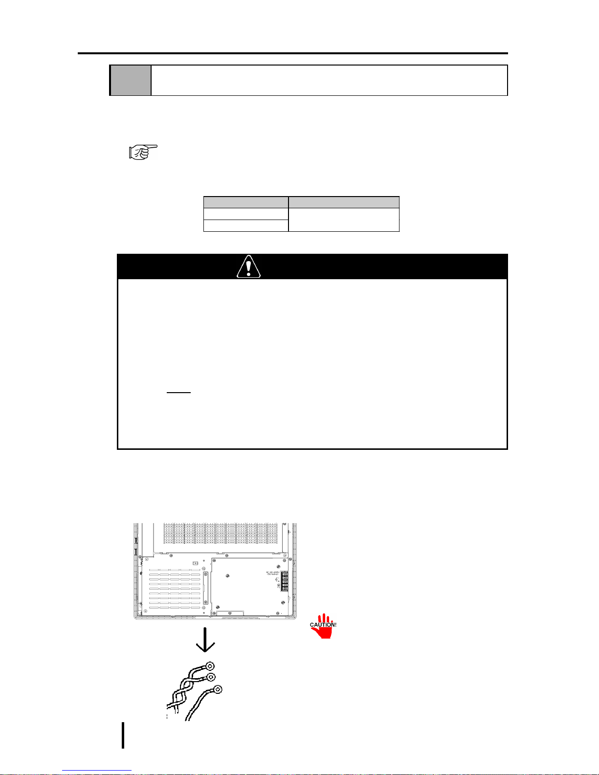
7 - 4
PL-6900 Series User Manual
Maintenance and Inspection
Follow the steps given below to change the PL’s backlight. Be sure to wear cotton
gloves when performing this work to prevent burns. Also, remove the PL from its
installation panel, and place it face down (as shown below) when performing this
work.
7-3 Changing the PL Backlight
The PL’s backlight can be changed after it wears out. The steps involved are
outlined below .
The steps for removing the Rear Maintenance Cover and the Half Cover are the
same for each PL unit.
Please use the following table to identify which backlight model number to use
when ordering your backlight.
WARNING
• Whenever changing the backlight, be sure the PL's power cord
has been disconnected and that the unit is cooled down.
• When the PL's power cord is connected and the PL is ON, high
voltage runs through the wires in the backlight area—do not touch
them!
• When the PL's power has just been turned OFF, the backlight area
is still very hot! Be sure to wear gloves to prevent being burned.
• Do not try to replace the backlight while the PL is installed in a
cabinet or panel. Remove the PL first, then begin the backlight
replacement procedures.
1) Unplug the PL's power cord from
the main power supply and then
disconnect the PL power cord
terminals from the PL's power
terminal block.
PL T ype Backlight T ype
PL- 6900T
PL- 6901T
GP675T-BL00-MS
Power Cord
(PL-6901T)
• Be sure to perform the backlight
changeover on a flat, level surface. This will prevent damage to
the PL unit and the accidental
cutting of any of its power cord
terminals.

7 - 5
PL-6900 Series User Manual
Maintenance and Inspection
2) Remove the PL’s four chassis attachment screws.
3) Hold both sides of the front panel
section and use your thumbs to slide
(push) the chassis forward (see
figure).
4) The chassis can then be pivoted back
and open.
Rear Face
Slide Forward
Top Face

7 - 6
PL-6900 Series User Manual
Maintenance and Inspection
5) Disconnect the power connectors
from the backlight lamps.
6) The backlights are both fixed in
place on the LCD unit with attachment screws. Remove these four
(4) screws.
Inverter Board
Connector
Backlight
Backlight
Connector
Inverter
Board
Backlight
Backlight
• Use an"0" sized Phillips screwdriver to remove the backlight attachment screws.
• Be careful not to lose any of the
small attachment screws.
• Do not let any attachment screws
fall inside the PL unit’s chassis or
front panel area, since it could
cause an electrical short.

7 - 7
PL-6900 Series User Manual
Maintenance and Inspection
7) Open/release each plastic cable tie
and remove each backlight’s
power cord.
Be sure not to pinch or cut the backlight’s
power cord between the PL’s chassis and
front panel. Whenever the PL unit is
opened, be sure that both backlight cables
are securely held by their cable ties.
Cable Tie

7 - 8
PL-6900 Series User Manual
Maintenance and Inspection
8) Remove the upper backlight
unit.
9) Insert the replacement backlight,
replace its two metal clips and
secure them in place with their
attachment screws.
10) Use the abovementioned steps 8)
and 9) to replace the bottom
backlight. After the backlights
are secured in place, reattach
their power connectors to the
Inverter Board.
• Be sure to always change both of
the PL backlights at the same
time.
• Be sure that the backlight’s
power cord connector is inserted
completely into the Inverter
Board’s receptacle. If not, the
PL may be damaged.
11) Reconnect the PL’s front panel
and chassis, being careful not
to pinch any electrical wires.
12) Replace the PL’s four(4)
chassis attachment screws.
Remove the
connector
Inverter Board
Backlight
When removing the
backlight unit, be sure
not to lose any of the
four (4) metal clips
used to hold the backlight in place, or their
attachment screws.
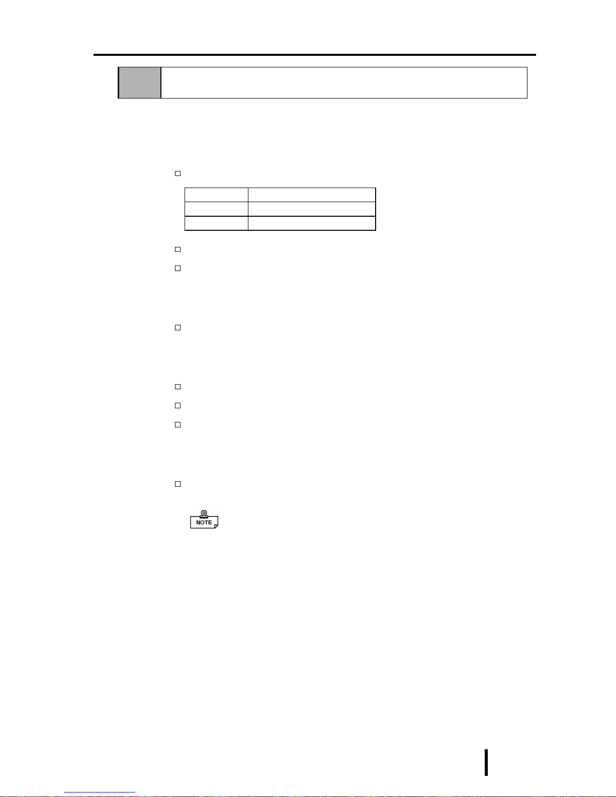
7 - 9
PL-6900 Series User Manual
Maintenance and Inspection
7-4 Periodic Check
Check the PL periodically to ensure it is in good working condition.
• Ambient environment check points
Is the ambient temperature within the specified range?
Is the ambient humidity within the specified range (30 %RH to 85 %RH) ?
Is the atmosphere free of corrosive gas ?
• Electrical specifications check
Is the voltage adequate (AC85 to 265V, 50/60 Hz) ?
• Installation check points
Is the connection cable firmly connected (not loose) ?
Are any bolts or screws loose ?
Are there any flaws or tears in the moisture resistant gasket ?
• Display check
Is the display bright enough ?
When the PL’s backlight needs to be replaced, please contact your
nearest authorized service center for prompt service.
Ambient Operating Temper ature
W/ PL Fan
5
o
C to 50oC
W/OUT PL Fan
5
o
C to 40oC

7 - 10
PL-6900 Series User Manual
Maintenance and Inspection
MEMO

App-1
PL-6900 Series User Manual
Appendix
1. Hardware Configuration
2. RAS Feature
Chapter
Appendix
1 Hardware Configuration
1 I/O Mapping
*1 : The game I/O is not used by the PL system, but is normally reserved.
Address AT system device
System-specific
device
0000H - 001FH DMA c ontroller (8237)
0020H - 003FH Interrupt cont rol ler (8259A)
0040H - 005FH Sy stem t i m er (8254)
0060H - 006FH Key board Controll er
0070H - 007FH Real-time cloc k, NMI mas k
0080H - 009FH DMA page regis t er
00A0H - 00BFH Interrupt controller 2 (8259A)
00C0H - 00DFH DMA cont roll er 2 (8237)
00F0H - 00FFH Numeric data proc essor
01F0H - 01 F F H Hard di sk (IDE )
0200H - 0207H Game I/ O *1
0290H - 0297H Res erved Sy s tem Monitor
0298H - 029FH Reserved RA S
02E8H - 02EFH Res erved
Touch Panel S erial
Port 4 (COM4 )
02F8H - 02FFH S eri al port 2 (COM2) : General Use
03B0H - 03BB H Video c ont roll er (VGA)
03BCH - 03BFH Parall el port 1 (LP T1)
03C0H - 03DFH Video cont roll er (V GA )
03E8H - 03EFH Res erved Serial port 3 (COM3)
03F0H - 03F7H Fl oppy di s k c ont roller
03F8H - 03FFH S eri al port 1 (COM1) : General Use

App-2
PL-6900 Series User Manual
Appendix
FFFF0000H
00100000H
000E0000H
000A0000H
000C0000H
000CC000H
FFFFFFFFH
00000000H
System ROM
Unused RAM
System ROM
Expanded ROM Area
VGA BIOS
(Display Adaptor)
Unused RAM
640 KB
System Board DRAM
~
~
~
~
2 Memory Mapping

App-3
PL-6900 Series User Manual
Appendix
3 IRQ Mapping
Hardware Interruption List
^
Des cription
NMI P arity E rror or I/O Channel Check
IRQ 0 Timer (in t he Chips et)
IRQ 1 Keyboard
IRQ 2 Cascade from Controll er 2
IRQ 3 Ser i al Port 2 (COM2): G enera l Use Port
IRQ 4 Ser i al Port 1 (COM1): G enera l Use Port
IRQ 5 Available for users
IRQ 6 Floppy Disk Controller
IRQ 7 Parallel P ort 1 (LP T1) : Printer Port
IRQ 8 Real Time Cloc k
IRQ 9 Ser i al Port 3 (COM3): G enera l Use Port
IRQ 10 S eri al Port 4 (COM4): Touch P anel
IRQ 11 A vailable for users
IRQ 12 PS/2 Mouse
IRQ 13 Numeric Data Processor
IRQ 14 Hard Di sk (IDE)
IRQ 15 A vailable for users
For 8-bit transmission
For 16-bit transmission
^
Description
DMA 0
DMA 1
DMA 2 Floppy disk controller
DMA 3
DMA 4 Cascade t o c ontroll er 1
DMA 5
DMA 6
DMA 7
DMA Channel List

App-4
PL-6900 Series User Manual
Appendix
RAS, which stands for Reliability , Availability and Serviceability, is a device-level
monitoring function that provides a variety of features to improve the reliability of
your PL system.
Though the standard set of RAS features used will vary depending on the devices
used, the following features are used to provide Alarm Monitoring and External
Input Signal support.
Alarm Monitoring
Power Voltage Alarm
Cooling Fan Alarm
Internal Temperature Alarm
Watchdog Timer Time Up
Mirror Disk Alarm
External Input Signal
Standard Signal Input (DIN 2 bit)
Remote Reset Input
Also, when either the one of the above mentioned alarms occurs, or an external
signal input is received, the following types of alarm processing output signals and
features are supported.
External Output Signal
Standard Signal Output (DOUT 1 bit)
Alarm Output (1 point)
Lamp Output (1 point)
Types of Processing (all
units)
LED Indicator (3-state display – 1 point)
Pop-up Message Output
Buzzer Output
System Shutdown
Furthermore, using the PL’s System Monitor feature (included in the PL’s software
utility disk), allows the easy setting and control (Enable/Disable) of the aforementioned Alarm Monitor and External Input Signals.
Last, the system monitor feature’s use of an Application Link Library (API-DLL)
allows it to also be used with other applications.
*1 When a Mirror Disk Alarm occurs and the standard RAS feature settings are used, the
alarm output is limited to the Mirror Disk unit’s LED indicator. (Alternately flashing orange
and green)
*2 The remote reset feature’s input can be either enabled or disabled, the alarm output setting
cannot be set to trigger a forced system reset.
*3 For System Monitor Feature details, refer to the accompanying Driver and Utility disk.
Chapter 6 - OS Setup
2 RAS Feature
1 PL’s RAS Features

App-5
PL-6900 Series User Manual
Appendix
Alarm Monitoring
Power Voltage Alarm
Monitors the condition of the PL’s internal and CPU power.
Cooling Fan Alarm
Monitors the condition of the PL’s internal power and CPU cooling fans.
Internal Temperature Alarm
Monitors the PL’s internal and CPU vicinity temperatures.
The degree of monitoring (3 levels) and the enabling or disabling of the above
three items is performed via the System Setup Area’s settings.
For detailed information about the monitoring level settings,
5-2 6 SYSTEM MONITOR UTILITY
This utility can also be used to enable or disable the above mentioned features, as
well as designate what type of processing is to be performed.
Watchdog Timer Time Up
This feature alternately writes Time Up Count values from the CPU to the RAS
feature’ s special programmable timer and then periodically clears them, which
provides a means of monitoring the CPU’ s performance. If the clearing of this
count value is stopped, the timer will overflow and an alarm will be detected. The
System Monitor utility can be used to enable or disable this feature, as well as
designate what type of processing is to be performed.
Mirror Disk Alarm
Whenever a disk crash, or other alarm event occurs to the optional Mirror Disk
unit, this unit’ s LED indicator will flash (either orange or green) to indicate there
is a problem.
This unit’ s error detection occurs independently of and cannot be set by the RAS
feature.
2 RAS Feature Details

App-6
PL-6900 Series User Manual
Appendix
External Input Signal
The PL’s RAS interface connector uses the following input signals.
Standard Signal Input (DIN)
This standard digital input is used for alarm detection in external devices. The
input signal uses two bits.
The System Monitor utility can be used to enable or disable this feature, as well as
designate what type of processing is to be performed once a signal is received.
Remote Reset Input
This is the reset signal sent from an external device to the PL. When this signal is
enabled, a forced reset of the PL is performed.
The System Monitor utility can be used to enable or disable this feature
External Input Signal (for both DIN and Remote Reset Input)
- External Power DC12V to DC24V connections are possible
- Input Protection Protection Diode
- Isolation Used (photo-isolation)
(Interface Circuit) (Connection Example)
Cable
DC12V to
DC24V
External
Power)
Reset Input(+)5pin
DIN0(+) 6pin
DIN1(+) 13pin
(DC12V to DC24V)
Input Port
R
PC357
Reset Input(-)11pin
DIN0(-) 12pin
DIN1(-) 24pin
Dsub 25Pin
Connector
+5V
3.3kΩ
1/4W
For connection pin location details,
2-3 5 RAS Interface

App-7
PL-6900 Series User Manual
Appendix
External Output Signal
The PL’s RAS interface connector uses the following output signals.
General Purpose Signal Output (DOUT)
This general purpose digital output signal provides system condition information
to external devices.
The System Monitor’s API-DLL are used by applications to control this signal.
Alarm Output (1 point)
Lamp Output (1 point)
The above mentioned general purpose digital output signals provide system
condition information to external devices.
The System Monitor utility can be used to enable or disable any of these output
signals.
Also, when alarm output is enabled, the orange colored LED indicator will also
blink.
External Output Signal (used for DOUT, Alarm Output, Lamp Output)
- Output Specification DC24V 100mA (MAX)
- Isolation Used (photo-isolation)
(Interface Circuit) (Connection Example)
Cable
Output
Port
R
PC357
Dsub 25 Pin
Connector
4.7kΩ
SST3904
DOUT(-) 7pin
Alarm Output(-) 9pin
Lamp Output(-) 21pin
DOUT(+) 8pin
Alarm Output(+) 10pin
Lamp Output(+) 22pin
+5V
For connection pin location details,
2-3 5 RAS Interface

App-8
PL-6900 Series User Manual
Appendix
Types of Processing (all units)
The PL provides system condition information via the following methods.
LED Indicator (3-state display – 1 point)
In addition to indicating if the unit’s power is ON or OFF, the 3-state LED indicator (power lamp) provides the following system condition information.
Pop-up Message Output
This feature uses the Windows® system’s pop-up message feature to indicate that
an alarm has occurred.
Buzzer Output
This feature uses the PL’s internal speaker to indicate the system’s condition.
System Shutdown
This feature shuts down the PL’s OS (Windows® 95/ Windows® 98 Second
Edition/ Windows® NT 4.0). The System Monitor utility can be used to enable or
disable this feature.
Color System Condition Output Crea ted
Green
Normal Operation ( P owe r ON) N one
Orange
RAS has d et ect ed a s ystem
alarm.
The alarm output set in t he
system monit or is enabl ed.
Flashing
Orange/ Green
Mirror Disk Alarm has occurred None

App-9
PL-6900 Series User Manual
Appendix
System Setup
Alarm Level Detection
Settings
+
Enable/Disable Settings
(Voltage, Fan RPM, Temp.)
System Monitor
Power Alarm
Watchdog
Timer
System Monitor Timeout
Time Setting
Shutdown
Processing
Enable
Disable
Settings
Output
Settings
Cooling Fan
RPM Alarm
Int. Temp. Alarm
CPU
Clear
Time Up
Buzzer Output
Pop-Up
Message
Alarm
Alarm
Alarm
RAS
Connector
General
Purpose Input
Remote Reset
Input
2 Bit
Hardware Reset
LED
Lights Orange
Blinks Orange/
Green
Lights Green
Mirror Disk
Alarm
Power ON
RAS
Conne-
ctor
General
Purpose
Signal Output
Lamp Output
Alarm Output
APIDLL
User Application
3 RAS Feature Overview
 Loading...