


GLC2300 Series
User Manual
Digital Electronics Corporation

Preface
Thank you for purchasing the Pro-face Graphic Logic Controller GLC2300 Series
(hereby referred to as “GLC” or “GLC unit”).
This controller features a number of improvements over the previous GLC series
including enhanced functions and advanced operability. Flex Network communication, Ethernet, and CF Card are available for the GLC2000 Series without
having to purchase and install an optional expansion unit.
Please read this manual carefully as it explains, step by step, how to use the GLC
correctly and safely .
Also, in this manual’s examples, the Mitsubishi MELSEC-AnA Series PLC is used
whenever possible, connected in a one-to-one relationship with a GLC.
< Note >
1. It is forbidden to copy the contents of this manual, in whole or in part,
except for the user’s personal use, without the express permission of Digital
Electronics Corporation of Japan.
2. The information provided in this manual is subject to change without notice.
3. This manual has been written with care and attention to detail; however,
should you find any errors or omissions, contact Digital Electronics Corporation and inform them of your findings.
4. Please be aware that Digital Electronics Corporation shall not be held liable
by the user for any damages, losses, or third party claims arising from any
uses of this product.
All Company/Manufacturer names used in this manual are the registered trademarks of those companies.
© Copyright 2001 Digital Electronics Corporation
GLC2300 Series User Manual 1

Preface
Table of Contents
Preface........................................................................................................................ 1
Table of Contents ...................................................................................................... 2
Essential Safety Precautions................................................................................... 6
General Safety Precautions .................................................................................. 12
About GLC2300 Series Models............................................................................ 14
Revision Information............................................................................................. 14
Package Contents ................................................................................................... 14
UL/c-UL (CSA) Application Notes ...................................................................... 15
CE Marking Notes ............................................................................................... 15
Documentation Conventions................................................................................. 16
CHAPTER 1 INTRODUCTION
1.1 Prior to Operating the GLC.......................................................................1-1
1.2 System Design............................................................................................... 1-2
1.3 Accessories ....................................................................................................1-6
1.4 GLC2300 Series Overview ......................................................................... 1-9
1.4.1 Ethernet Connectivity......................................................................1-10
1.4.2 CF Card ............................................................................................ 1-11
1.4.3 Expansion Serial Interface..............................................................1-12
1.4.4 Flex Network Communication Interface........................................ 1-13
1.4.5 Serial Device / Tool Connector Interface ......................................1-14
1.4.6 2–Port Feature..................................................................................1-14
1.4.7 Backlight Burnout Detection Feature............................................. 1-16
CHAPTER 2 SPECIFICATIONS
2.1 General Specifications ................................................................................. 2-1
2.1.1 Electrical ............................................................................................ 2-1
2.1.2 Environmental.................................................................................... 2-2
2.1.3 Structural............................................................................................ 2-2
2.2 Functional Specifications............................................................................2-3
2.2.1 Display ...............................................................................................2-3
2.2.2 Memory .............................................................................................. 2-4
2.2.3 Control Memory ................................................................................ 2-4
2.2.4 Resolution / Clock............................................................................. 2-4
2.2.5 Interfaces ............................................................................................ 2-5
GLC2300 Series User Manual2

2.3 Interface Specifications...............................................................................2-6
2.3.1 Serial Interfaces ................................................................................. 2-6
2.3.2 Flex Network Communication Interface.......................................... 2-8
2.4 Part Names and Functions .........................................................................2-9
2.5 Dimensions .................................................................................................. 2-11
2.5.1 GLC2300 External Dimensions ...................................................... 2-11
2.5.2 Installation Fasteners.......................................................................2-12
2.5.3 Panel Cut Dimensions..................................................................... 2-13
CHAPTER 3 INSTALLATION AND WIRING
3.1 Installation .................................................................................................... 3-1
3.1.1 Installation Procedures...................................................................... 3-1
3.2 Wiring Cautions........................................................................................... 3-5
3.2.1 Connecting the Power Cord.............................................................. 3-5
3.2.2 Connecting the Power Supply ..........................................................3-7
Preface
3.2.3 Grounding .......................................................................................... 3-8
3.2.4 I/O Signal Line Cautions .................................................................. 3-9
3.2.5 Installation Cautions ......................................................................... 3-9
3.3 Tool Connector ........................................................................................... 3-12
3.3.1 Serial Printer Connection................................................................3-12
3.4 Ethernet Cable Connector........................................................................3-18
3.5 CF Card Insertion and Removal ............................................................. 3-18
3.5.1 CF Card Handling ............................................................................ 3-21
3.6 Flex Network Communication Cable .....................................................3-22
3.6.1 Cable Preparation ............................................................................3-22
3.6.2 Flex Network Communication Cable Wiring................................3-22
CHAPTER 4 DATA TRANSFER
4.1 Serial Data Transfer.................................................................................... 4-1
4.2 Ethernet Data Transfer...............................................................................4-3
4.2.1 Checking the IP Address................................................................... 4-5
4.3 CF Memory Loader Tool ............................................................................4-6
4.3.1 Data Upload and Download..............................................................4-7
CHAPTER 5 OFFLINE MODE
5.1 Entering OFFLINE Mode .......................................................................... 5-1
5.1.1 After Plugging in the Power Cord.................................................... 5-2
5.1.2 From the Menu Bar ...........................................................................5-2
GLC2300 Series User Manual 3

Preface
5.2 OFFLINE Mode Main Menu ..................................................................... 5-3
5.3 INITIALIZATION.......................................................................................5-4
5.4 SELF-DIAGNOSIS...................................................................................... 5-6
CHAPTER 6 INITIALIZING THE GLC
6.1 Initialization Screen ....................................................................................6-1
6.2 Initialization Items ....................................................................................... 6-2
6.3 System Environment Setup ........................................................................6-3
6.3.1 SYSTEM SETUP .............................................................................. 6-3
6.3.2 SYSTEM AREA SETUP .................................................................. 6-4
6.3.3 GLOBAL WINDOW SETUP ........................................................... 6-5
6.3.4 CHARACTER STRING DATA SETUP .......................................... 6-6
6.4 SET UP I/O ...................................................................................................6-9
6.4.1 SET UP SIO....................................................................................... 6-9
6.4.2 COMMUNICATION SETUP .........................................................6-10
6.4.3 SET UP TOUCH PANEL................................................................ 6-11
6.4.4 DISPLAY SETUP............................................................................6-15
6.4.5 PRINTER SETUP ...........................................................................6-15
6.4.6 EXPANSION SERIAL SETUP ......................................................6-16
6.4 .7 EXPANS ION SER IAL ENVIRONME NT SETUP ....................... 6-17
6.4.8 Set Up Capture Operation............................................................... 6-18
6.4.9 FUNCTION SETUP........................................................................6-19
6.4.10 COMMUNICATION PORT SETUP.............................................. 6-19
6.5 PLC SETUP ................................................................................................ 6-20
6.5.1 SET UP OPERATION SURROUNDINGS (1:1/n:1).................... 6-20
6.5.2 STATION SETUP (n:1)................................................................... 6-21
6.5.3 CUSTOMIZE SETUP (n:1)............................................................6-23
6.5.4 ETHERNET SETUP ...................................................................... 6-25
6.5.5 SYSLOG SETUP.............................................................................6-26
6.5.6 OTHERS SETUP.............................................................................6-26
6.5.7 SELF-DIAGNOSIS .........................................................................6-27
6.5.8 Controller Settings........................................................................... 6-27
6.6 INITIALIZE MEMORY........................................................................... 6-29
6.6.1 INITIALIZE MEMORY..................................................................6-29
6.6.2 INITIALIZE CF CARD...................................................................6-30
6.6.3 CSV DATA INDEX.........................................................................6-30
6.7 SET UP TIME ............................................................................................6-31
6.8 SET UP SCREEN ......................................................................................6-32
6.9 Font Setting.................................................................................................6-33
GLC2300 Series User Manual4

CHAPTER 7 RUN MODE AND ERRORS
7.1 RUN Mode.....................................................................................................7-1
7.1.1 After Connecting the Power Cord....................................................7-1
7.1.2 Via OFFLINE Mode .......................................................................... 7-2
7.2 SELF-DIAGNOSIS...................................................................................... 7-3
7.2.1 SELF-DIAGNOSIS ITEM LIST....................................................... 7-3
7.2.2 SELF-DIAGNOSIS – Details ...........................................................7-4
7.2.3 CONTROLLER SELF-DIAGNOSIS ............................................... 7-7
7.3 Troubleshooting............................................................................................ 7-8
7.3.1 Possible Types of Trouble.................................................................7-8
7.3.2 No Display ......................................................................................... 7-9
7.3.3 No GLC / Host Communication..................................................... 7-12
7.3.4 Touch Panel Does Not Respond ..................................................... 7-14
7.3.5 Cannot Execute Logic Program......................................................7-15
Preface
7.3.6 Buzzer Sounds when GLC Power is Turned ON ..........................7-16
7.3.7 Clock Settings Cannot be Entered..................................................7-17
7.3.8 Error Screens ...................................................................................7-17
7.4 Error Messages...........................................................................................7-18
7.4.1 Error Message List .......................................................................... 7-18
7.5 Error Message Details...............................................................................7-20
7.5.1 System Errors...................................................................................7-20
7.5.2 Illegal Address Screen Data............................................................7-22
7.5.3 PLC COM. Error .............................................................................7-23
7.5.4 Clock Setup Error............................................................................ 7-24
7.5.5 Screen Tag Limit Exceeded (max. 384)......................................... 7-25
7.5.6 OBJ. PLC Has Not Been Set Up .................................................... 7-25
7.5.7 D-Script and Global D-Script Errors .............................................7-25
7.5.8 Extended SIO Script Error..............................................................7-26
CHAPTER 8 MAINTENANCE
8.1 Regular Cleaning ......................................................................................... 8-1
8.1.1 Cleaning the Display ......................................................................... 8-1
8.1.2 Installation Gasket Check / Replacement........................................ 8-1
8.2 Periodic Check Points ................................................................................. 8-2
8.3 Replacing the Backlight..............................................................................8-3
INDEX
GLC2300 Series User Manual 5
Preface
Essential Safety Precautions
This manual includes procedures that must be followed to operate the GLC correctly and safely. Be sure to read this manual and any related materials thoroughly
to understand the correct operation and functions of the GLC unit.
Safety Symbols
Please pay attention to the following safety symbols and their meanings:
Indicates situations that will definitely
result in major machine damage, severe
DANGER
WARNING
bodily injury, or death if the instructions are
not followed.
Indicates situations that may result in major
machine damage, severe bodily injury, or
death if the instructions are not followed.
Indicates situations that may result in
CAUTION
damage to the machinery, or minor bodily
injury if the instructions are not followed.
DANGERS
When Designing your GLC System:
• Be sure to design your GLC control system so that, in the
event of a main power supply failure or a GLC accident, the
user system’s overall safety integrity will be maintained. If
this is not done, incorrect output signals or a GLC malfunction may cause an accident.
(1) Interlock and other circuits designed to interrupt or op-
pose normal machine movement (such as Emergency
Stop, General Protection, and forward and reverse rotation), as well as those designed to prevent machine damage (such as upper, lower, and traverse movement limit
positioning) should all be located outside of the GLC.
(2) When the GLC generates a “Watchdog Timer Error ,” GLC
operation will halt. Also, when Errors occur in Input/Output control areas that the GLC cannot detect, unexpected
movement may occur in those areas. Therefore, and to
prevent unsafe machine movement, create a “Failsafe Circuit” that is completely external to the GLC.
GLC2300 Series User Manual6

Preface
DANGERS
(3) If a problem arises with an external unit’s relay or transis-
tor , causing an output (coil) to remain either ON or OFF, a
major accident can occur . To prevent this, be sure to set
up external watchdog circuits that will monitor vital output signals.
• Design a circuit that will supply power to the GLC unit’s
I/O before starting up the GLC. If the GLC unit’s internal program enters RUN mode prior to the I/O unit’s load control
power turning ON, an incorrect output (signal) or malfunction
could cause an accident.
• Design a user program to ensure the safety of the user’ s sys-
tem in the event of a GLC display or control error , or either a
data transmission error or power failure between the GLC
and a connected unit — all of which can lead to an incorrect
output (signal) or malfunction, resulting in an accident.
• Do NOT make switches using the switches on the touch pan-
els which may cause operator injury and machine damage.
To prevent major accidents caused by an output remaining
either ON or OFF, set up circuits (such as limiters) that will
monitor vital output signals. To prevent accidents caused by
incorrect output or malfunction, design switches used by separate devices to perform important operations.
• Do NOT use GLC touch panel switches to perform operator
safety-related or important accident-prevention operations.
These operations should be performed by separate hardware
switches to prevent operator injury and machine damage.
• T o prevent any possibility of bodily injury or material damage,
design your system so that equipment will not malfunction
due to a communication fault between the GLC and its host
controller .
• Do NOT use the GLC as a warning device for critical warning
alarms that can cause serious operator injury, machine damage, or production stoppage. Use stand-alone hardware and/
or mechanical interlocks to design alarm indicators and their
control/activator units.
GLC2300 Series User Manual 7
Preface
DANGERS
• The GLC is not appropriate for use with aircraft control devices, medical life-support equipment, central trunk data transmission (communication) devices, or nuclear power control
devices, due to their inherent requirements of extremely high
levels of safety and reliability.
• When using the GLC with transportation vehicles (trains, cars,
and ships), disaster and crime prevention devices, various
types of safety equipment, and medical devices that are not
life-support related, use redundant and/or failsafe system
designs to ensure proper reliability and safety.
WARNINGS
• Unlike the GLC unit’s “Standby Mode,” after the GLC unit’ s
backlight burns out, the touch panel is still active. If the
operator fails to notice that the backlight is burned out and
touches the panel, a potentially dangerous machine
misoperation can occur. Your backlight is burned out if:
• your GLC is not set to “Standby Mode” and the screen
has gone blank
• your GLC is set to “Standby Mode,” but touching the
screen does not cause the display to reappear
To prevent accidental machine misoperation, Pro-face recommends that you use the GLC unit’s “
AFTER BACKLIGHT BURNOUT
detect a burnout and disable the touch screen.
Installation Warnings:
” feature, to automatically
USE TOUCH PANEL
• High voltage runs through the GLC. T o prevent an electrical
shock, do NOT disassemble the GLC for any reason other
than to replace the backlight.
• Do NOT modify the GLC unit. Doing so may cause a fire or
an electrical shock.
• Do NOT use the GLC in an environment where flammable
gases are present, to prevent an explosion from occurring.
GLC2300 Series User Manual8

Preface
WARNINGS
Wiring Warnings:
• To prevent electrical shock or equipment damage, unplug
the GLC unit’s power cord from the power supply prior to
installing or wiring the GLC.
• After completing any GLC wiring work, be sure the termi-
nal block’s protective plastic cover is reattached. If this
cover is not reattached, an electrical shock could easily
occur .
• Do NOT use power levels with the GLC that are higher or
lower than the GLC unit’s specified power range. Doing so
may cause a fire, electrical shock, or GLC damage.
Operation and Maintenance Warnings:
• NEVER touch a live power terminal. Doing so could cause
an electrical shock or a machine malfunction.
• T o prevent an electrical shock, unplug the GLC unit’ s power
cord before either cleaning the GLC or attaching/detaching the power terminal attachment screws.
• When replacing the GLC unit’s backlight, be sure to un-
plug the unit’s power cord to prevent an electrical shock,
and wear safety gloves to prevent burns.
• The GLC uses a lithium battery to back up its internal clock
and to control memory data. If the battery is incorrectly replaced (reversed positive [+] and negative [-] ends), the battery may explode. Therefore, Pro-face recommends that you
contact your local GLC distributor for instructions before
replacing or changing the battery.
GLC2300 Series User Manual 9
Preface
CAUTIONS
Wiring Layout Cautions:
• To prevent a GLC unit malfunction due to excessive noise,
isolate all GLC input/output signal lines from all power wiring
or power cables via a separate wiring duct.
Installation Cautions:
• T o reduce the risk of incorrect input or output signals, be sure
that any data cables attached to the GLC unit’s connector
make full contact with the connector pins.
General Wiring Cautions:
• To prevent electrical shocks or malfunctions, be sure the
GL C unit’s FG (earth) wire is grounded as follows:
(1) maximum grounding resistance: 100
(2) minimum grounding wire diameter: 2 mm
ΩΩ
Ω
ΩΩ
2
• The cables connected to the GLC should be secured by cable
clamps to prevent weight or tension of the cables added to
the connectors or terminals.
• The GLC unit’s wiring should be checked to confirm that both
the operating voltage and wiring terminal locations are correct. If either the voltage or the wiring terminal location is
incorrect, it can cause a fire or accident.
• Be sure to secure all wiring terminal screws with the designated torque. Screws and terminals that become loose can
cause a short circuit, fire, or accident.
• Be sure that metal filings or wiring remnants do not fall inside
the GLC, since they can cause a fire, accident, or malfunction.
GLC Operation and Maintenance Cautions:
• Be sure to read the GLC unit’s manual and online help information carefully before performing program changes, entering forced output, or using the RUN, STOP, or PAUSE commands while the GLC is operating. Mistakes made when
using these items can cause machine accidents or damage.
GLC2300 Series User Manual10
Preface
CAUTIONS
• Be sure the electricity is turned OFF before attaching or
detaching an I/O unit. If the electricity is ON when an I/O
unit is attached or detached, damage or malfunction to the
I/O unit may occur.
• The liquid crystal panel contains a powerful irritant. If, for
any reason, the panel is damaged and this liquid enters
your eyes, flush your eyes for 15 minutes with running water
and contact a physician immediately.
• Prior to inserting or removing a CF Card, and to prevent
damage to or loss of the CF Card’s internal data, turn the
GLC unit’s CF Card ACCESS switch OFF, and make sure
that the ACCESS lamp is not lit.
• While a CF Card is being accessed, NEVER:
• turn OFF the GLC
• reset the GLC
• insert a CF Card
• remove a CF Card
Prior to performing these operations, create and use a spe-
cial GLC application screen that will prevent access to the
CF Card.
Refer to the GP-PRO/PB III for Windows Tag Reference Manual
(included in the GP-PRO/PB III C-Package).
GLC Unit Disposal Cautions:
• The GLC unit should be disposed of in a manner appropri-
ate to, and in accordance with, the user country’s industrial machinery disposal standards.
GLC2300 Series User Manual 11

Preface
General Safety Precautions
• Do NOT strike the touch panel with a hard or pointed object, or press
on the touch panel with too much force, since it may damage the touch
panel or the display.
• Do NOT install the GLC where the ambient temperature can exceed the
allowed range. Doing so may cause the GLC to malfunction or shorten
its operation life.
• Do NOT restrict or limit the GLC unit’s naturally-occurring, rear-face
ventilation, and do NOT store or use the GLC in overheated areas.
• Do NOT store or use the GLC unit in areas where large, sudden tem-
perature changes can occur. These changes can cause condensation to
form inside the unit, which can cause possible unit malfunctions.
• Do NOT allow water, liquids, metals, or charged particles to enter inside
the GLC unit’s outer casing, since they can cause either a GLC malfunction or an electrical shock. The allowable pollution degree is 2.
• Do NOT store or use the GLC in direct sunlight, or in excessively dusty
or dirty environments.
• Do NOT store or use the GLC in an environment where shaking or ex-
cessive vibration can occur.
• Do NOT store or use the GLC where chemicals (such as organic sol-
vents and acids) can evaporate, or in environments where chemicals
and acids are present in the air.
Corrosive chemicals: acids, alkalines, liquids containing salt
Flammable chemicals: organic solvents
• Do NOT use paint thinner or organic solvents to clean the GLC.
• Do NOT store or operate the LCD (Liquid Crystal Display) in areas that
receive direct sunlight, since the sun’s ultraviolet (UV) rays may cause
the quality of the LCD to deteriorate.
• Storing this unit in areas at temperatures that are lower than is recom-
mended in this manual’s specifications may cause the LCD panel’s liquid to congeal, which may damage the panel. Conversely, if the storage
area’s temperature becomes higher than the allowed level, the LCD
panel’ s liquid will become isotropic, causing irreversible damage to the
LCD. Therefore, be sure to store the panel only in areas where temperatures are within the ranges specified in this manual.
• Due to the possibility of unexpected accidents, be sure to back up the
GLC unit’s screen data/logic program regularly.
GLC2300 Series User Manual12

Preface
About the GLC Unit’s Display Panel
• The data that is currently displayed on the GLC unit’s screen, the screen’s
brightness, and the GLC unit’s voltage
sity of Contouring — wavelike pattern that is created when some parts
of the screen are brighter than others.
• The minute, dark and light grid-points on the display panel’s surface are
part of the GLC unit’s design and are not defects.
• Extended shadows, or “crosstalk,” may appear on the sides of screen
images. This is normal for an LCD panel.
• Sometimes the display area may look as if the display colors have
changed.
• Displaying a single image for long periods of time can cause an afterimage to remain when the screen display is changed.
To prevent this effect:
Use the GLC unit’s “Standby Mode,” which automatically turns the
screen OFF when no input is entered within a specified period of
time.
This is a common attribute of LCDs and is not a defect.
*1
each affect the screen’s inten-
See 6.3.1 – “System Setup.”
• Write “FFFFh” to the System Data Area’s “Screen Display Off” address
to turn the screen display OFF when the following actions are not performed within the user-specified period of time.
• Change Screen
• T ouch Screen
• Alarm Display
Do NOT display any single screen for a long period of time. Try to
change the screen display periodically.
1. The backlight’s brightness may vary or its lighting may be delayed if the voltage
provided is low — even if still within the range of rated voltage listed in the specifications. When the voltage is high, the backlight’s lifetime may be shortened. As a rule,
voltage should be within five percent (5%) of rated voltage.
2. The following addresses assume all System Data Area settings are entered. If they are
not all entered, the correct word address may be different, since the following addresses are relative, not fixed, addresses.
With the Direct Access Method — use System Data Area word address +9
With the Memory Link Method — use System Data Area word address +12
*2
Refer to the GP-PRO/PB III for Windows Device/PLC Connection Manual (included in the GP-PRO/PB III C-Package).
GLC2300 Series User Manual 13
Preface
About GLC2300 Series Models
The GLC2300 Series in this manual refers to the following GLC model numbers:
GP Type with
Screen Creation
Software
GLC2300L
GLC2300
Series Name
GLC 2300 Series
Model
Name
GLC2300L
GLC2300T
Model
Number
GLC2300-
LG41-24V
GLC2300-
TC41-24V
Comme nts
UL/c-UL Approv ed
CE Marked
UL/c-UL Approv ed
CE Marked
Revision Information
Use the metallic label attached to the rear of the GLC to identify your unit’s
revision code. This code is at the bottom of the label, to the right of “REV”.
Inthis example, the asterisk mark (*) is in the “D” position, which means this
unit’s revison code is “D”.
DIGITAL ELECTRONICS CORP.
Package Contents
Please verify that the GLC unit’s packing box contains all the items listed below.
GLC2300 Unit (1)
Screw Lock Terminal Block
Installation Guide (1)
Installation Fasteners (4/set)
Installation Gasket
Special care and attention have been given to the packaging of this GLC unit.
However, if any of the items are damaged or missing, contact your local GLC
distributor immediately for prompt service.
This GLC2300 Series User Manual is sold separately.
GLC2300 Series User Manual14

Preface
UL/c-UL (CSA) Application Notes
The GLC2300-LG41-24V/GLC2300-TC41-24V units are UL/c-UL(CSA) recognized components.
UL file no. E231702(UL60950+UL1604)
When applying for UL approval for a product that includes one of these GLC
units, please be sure to pay special attention to the fact that all products with
built-in GLC units require UL inspection of the combination of the GLC and the
product.
The GLC components conform to the following standards:
- UL1604
Safety of Information T echnology Equipment for use in Class I and II, Division 2,
and Class III Hazardous (classified) locations.
- CAN/CSA-C22.2 No.60950-00 and No.213-M1987
Safety of Information T echnology Equipment for use in Class I and II, Division 2,
and Class III Hazardous (classified) locations.
GLC2300-LG41-24V (UL Registration Model: 2980070-11)
*1
and UL60950 Third Edition
GLC2300-TC41-24V (UL Registration Model: 2980070-12)
Installation Precautions
If the GLC is mounted so as to cool itself naturally , please mount it on a vertical panel. Also,
insure that the GLC is mounted at least 100 mm away from any other adjacent structures or
machine parts. If these conditions are not met, the heat generated by the GLC’s internal
components may cause it to fail to meet UL standards.
UL1604 - Compliance and Handling Cautions
1. Power and input/output wiring must be in accordance with Class I, Division 2 wiring methods - Article 501-4(b) of the National Electrical Code, NFP A 70 within the United States,
and in accordance with Section 18-152 of the Canadian Electrical Code for units installed
within Canada.
2. Suitable for use in Class I, Division 2, Groups A, B, C, and D Hazardous Locations.
3. W ARNING: Explosion hazard - substitution of components may impair compliance
to Class I, Division 2.
4. W ARNING: Explosion hazard - when in hazardous locations, turn the power OFF
before replacing or wiring modules.
5. W ARNING: Explosion hazard - confirm that the power supply has been turned OFF
before disconnecting equipment, or confirm that the
location is not subject to the risk of explosion.
6. W ARNING: Explosion hazard - do not connect/disconnect equipment unless area is
known to be nonhazardous. Port is for system set
up and diagnostics.
CE Marking Notes
The GLC2300-LG41-24V and GLC2300-TC41-21V are CE marked products that
conform to EMC directives EN55022 Class A and EN50082-2.
* For detailed CE marking information, contact your local GLC distributor.
*1 GLC2300-LG41-24V units with revision code “L” or later, GLC2300-TC41-24V
units with revision code “J” or later ar e all UL1604 compliant. See “Revision
Information” in page 14 for how to identify your unit’s revision code.
GLC2300 Series User Manual 15
Preface
Documentation Conventions
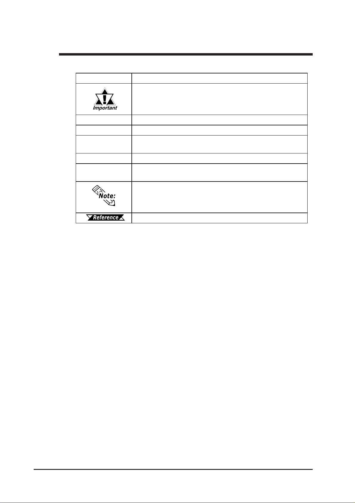
The list below describes the documentation conventions used in this manual.
Symbol Meaning
Indicates important inf ormation or procedures t hat must be f ollowed
for correct and risk-f r ee s of t ware/device operation.
Pro-Control Editor
GLC
C-Package
Screen Editor
Logic Program
Sof t w are us ed to create, tr ans f er , and monit or a GLC logic program.
Indicates t he GLC2300L/GLC2300T unit.
Indicates the software package that combines GP-PRO/PB III for
Window s and P r o- Control Editor.
GP-PRO/PB III for Windows screen editor s of tware (ver. 6. 10 or high er)
Ladder progr am created wit h t h e Pr o- Cont r ol E dit or (ver. 4.23 or
higher)
Provides us ef ul or important supplemental infor mation.
Cross- references t o us ef ul or important s upplemental information.
GLC2300 Series User Manual16

1. Prior to Operating the GLC
2. System Design
3. Accessories
Chapter
4. GLC2300 Series Overview
1 Introduction
1.1 Prior to Operating the GLC
Use the following steps to create projects for the GLC unit.
1. Preparation – Before using the GLC, make sure that you have all the required
hardware and have read all specification, wiring, and installation
information.
Chapter 2 – “Specifications” and Chapter 3 – “Installation and Wiring”
2. Screen Design – Create a sample screen and design a Tag layout with the Screen
layout sheets and Tag lists provided in the Editor software.
3. Install Screen Editor and Logic Program Development Software – Install
GP-PRO/PB III C-Package in your PC.
Refer to the GP-PRO/PB III for Windows Installation Guide.
4. Develop Logic Program – Develop a logic program using Pro-Control Editor and
designate the operation mode.
Refer to the Pro-Control Editor Operation Manual (included in the
GP-PRO/PB III C-Package).
5. Create Screens – Create screens using GP-PRO/PB III for Windows.
Refer to the GP-PRO/PB III for Windows Operation Manual (included
in the GP-PRO/PB III C-Package).
6. Screen/Transfer Logic Program – Transfer your logic program to the GLC using
GP-PRO/PB III for Windows.
Refer to the Pro-Control Editor Operation Manual (included in the
GP-PRO/PB III C-Package).
7. Monitor – Check the transferred program’s operation using the monitor feature of
Pro-Control Editor.
Refer to the GP-PRO/PB III for Windows Operation Manual (included
in the GP-PRO/PB III C-Package).
8. Initial Set Up – Enter your GLC unit’s Initial Settings, if necessary.
Refer to the GP-PRO/PB III for Windows Device/PLC Connection
Manual (included in the GP-PRO/PB III C-Package).
9. Operation – Connect the GLC unit’s I/O unit to your peripheral devices (such as
temperature controllers or inverters), and begin operation.
Refer to the GP-PRO/PB III for Windows Device/PLC Connection
Manual (included in the GP-PRO/PB III C-Package), and the Flex
Network User Manual.
GLC2300 Series User Manual 1–1
Chapter 1 – Introduction
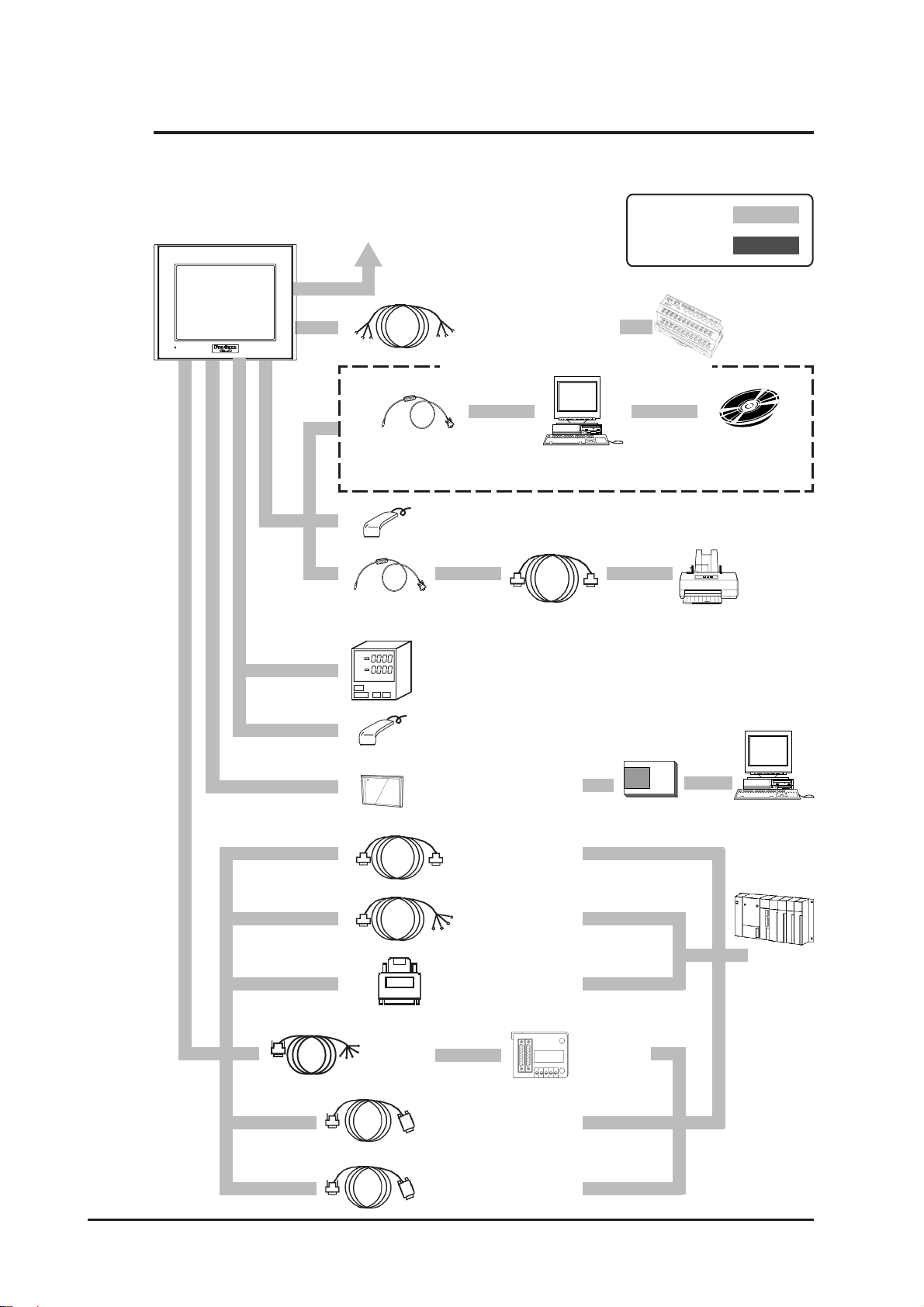
1.2 System Design
The following diagram represents the main selection of devices connectable to the GLC.
GLC RUN Mode Peripherals
GLC2300 Unit
To an Ethernet Network
(1)
(2)
RUN Mode
Edit Mode
Flex Network
Communication Cable
FN-CABLE2010-31-MS
FN-CABLE2050-31-MS
FN-CABLE2200-31-MS
When using the Internal 2-Port feature
Flex
Network
I/O Unit,
Analog Unit
(6)
(5)
(4)
(3)
Data Transfer Cable
GPW-CB02
Bar Code Reader*
(Recommended Type)
Data Transfer Cable
GPW-CB02
Temperature
Controllers,
Boards, etc.
Bar Code Reader,
2-D Code Reader*
(Commercial Type)
CF Card
CA3-CFCALL/64MB-01
CA3-CFCALL/128MB-01
CA3-CFCALL/256MB-01
CA3-CFCALL/512MB-01
2-Port Adapter
II Cable
GP070-MDCB11
Mitsubishi PLC A-Series
Program Port I/F Cable
GP430-IP10-O
Personal
Computer
2
Conversion Cable
(User Made)
2
RS-232C Cable
GP410-IS00-O*
RS-422 Cable
GP230-IS11-O*
GP230-IS12-O*
(for Multi-link cable)
3
3
3
RS-422 Connector
Terminal Adapter
GP070-CN10-O*
3
CF Card Adapter
GP077-CFAD10
Mitsubishi PLC
A, Q, C, FX Series
2-Port
Adapter II
GP070-MD11
Mitsubishi GPP
Software*
Printer
(Commercial
type)
Personal
Computer
(7)
(8)
Host
Controller
(PLCs, etc.)
(9)
1
*2
Mitsubishi PLC FX-Series
Program Port I/F Cable
GP430-IP11-O
GLC2300 Series User Manual1–2

GLC Edit Mode Peripherals
GLC2300 Unit
To an Ethernet Network
Chapter 1 – Introduction
(5)
(1)
(3)
Data Transfer Cable
GPW-CB02
CF Card
CA3-CFCALL/64MB-01
CA3-CFCALL/128MB-01
CA3-CFCALL/256MB-01
CA3-CFCALL/512MB-01
GLC Interfaces
(1) Ethernet
(2) Flex Network Commu-
nication Interface
(3) Tool Connector
(4) Expansion Serial
Interface
(5) CF Card Slot
(6) Serial Interface
Personal
Computer*
PLC Interfaces
(7) RS-232C Port
(8) RS-422 Port
(9) Programming
Console Port
GLC Comprehensive
4
CF Card Adapter
GP077-CFAD10
Development Software
GP-PRO/PB III CPackage-01 software
GPPRO-CNT01W-P01
1. For information about compatible PLC types and software, refer to
the GP-PRO/PB III for Windows Device/PLC Connection Manual
(included in the GP-PRO/PB III C-Package).
2. For information about recommended units, please see the following section.
3. Certain PLC types and models cannot be connected.
Refer to the GP-PRO/PB III for Windows Device/PLC Connection Manual (included in the GP-PRO/PB III C-Package).
4. For the full range of compatible PCs, refer to the following manual.
Refer to the GP-PRO/PB III for Windows Operation Manual
(included in the GP-PRO/PB III C-Package).
GLC2300 Series User Manual 1–3
Chapter 1 – Introduction
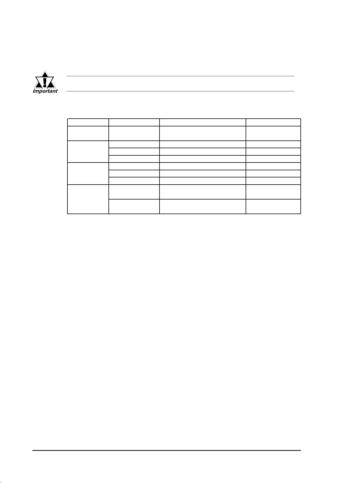
Recommended Units
The following tables list I/O devices that have been confirmed to be compatible
with the GLC. If you connect a device that is not listed below, be sure to confirm
that the unit functions correctly using the actual unit.
Recommended units are subject to additions/changes without notice.
Bar Code Readers (Connected to Tool Connector)
Manufacturer Model Type Description
Aim ex
Corpor ation
OPT Electronics
Tohken
NEC Infrontia
BR-331 PC2 Pen
OPT-1125-RSK-98 Set T ouch Scanner (Read Width: 60mm)
OPT-5125-RSK-98 Set T ouch Scanner (Read Width: 80mm)
OPL-6735-RSK-98 Set Laser Scanner
TCD -5510M Touch Scanner (Read Width: 65mm)
TCD -5510L Touch Scanner (Read Width: 82mm)
TCD -5510W Touch Scanner (Read Width: 105mm)
BCK5435-STA
BCK5535-STA
Touch Scanner (Read Width: 56mm)
Touch Scanner (Read Width: 85mm)
Includes Y cable for
*1*2
connection cable
Includes Y cable for
*1*2
connection cable
*1 Be sure to use the Y cable included with the unit and connect it between GLC unit and
a bar code reader. Data cannot be read correctly, if a non-"Y" cable is used, or if the
bar code reader is connected directly to the GLC unit.
*2 The following settings must be entered prior to using the bar code reader with a GLC
unit.
1) Set the CAPS.
2) Add the Carriage Return (CR) in the Postamble's settings.
For the details about these settings, please refer to the Installation Guide included
with the bar cord unit.
GLC2300 Series User Manual1–4
Chapter 1 – Introduction
Bar Code Readers (Connected to Expansion Serial Interface)
Ma nufa cturer Mode l No. Type Pow er Supply
BR-730RS Pen Batt ery powered
Aimex Corporati on
OPT Electronics
BR-530RS Pen
BW-665RS
OPT-1125-
RS232C(D02)
OPT-5125-
RS232C(D01)
Touch Scanner
(
Read Width: 65mm)
Touch Scanner
Read Width: 60mm)
(
Touch Scanner
Read Width: 80mm)
(
Requires separately-sold
BB-60 for power.
Requires separately-sold
DC5300T for power.
LS4004 Laser Scanner Includes power supply.
Symbol Technologies, Inc.,
LS4004i Laser Scanner Includes power supply.
LS6004 Laser Scanner Includes power supply.
LSH3502AHV Laser Scanner Includes power supply.
Keyence Co. BL-80R
HC36TR
Denso Co.
HC61TR
Touch Scanner
(
Read Width: 105mm)
Touch Scanner
Read Width: 61mm)
(
Touch Scanner
(
Read Width: 61mm
Includes power supply.
For power: P-200 unit; for
connector cable: KRS-423XF1K. Sold separately
(Sanwa Supply)
)
*1
1. Be sure to confirm that the Expansion Serial Interface’s settings match those of the
connected device.
See 6.4.6 – “Expansion Serial Setup.”
2-D Code Reader (Connected to Expansion Serial Interface)
Ma nufacturer M odel No. Pow er Supply
Tohken ESA-1220A (Sold separately)
Denso Supplied with the main uni t
1. Be sure to confirm that the Expansion Serial Interface’s settings match those of the
THIR-3000
THIR-3000H
QS20H
QS20H-I
*1
connected device.
See 6.4.6 – “Expansion Serial Setup.”
Serial Printer
Manufacturer Model No.
Hewlett Packard Company hp LaserJet 4pj
NADA Electronics, Ltd. TP-651G
SEIKO EPSON CORP TM-U210PD
CUSTOM Engineering FT190SP
GLC2300 Series User Manual 1–5
Chapter 1 – Introduction
1.3 Accessories
All optional equipment listed here is produced by Digital Electronics Corporation.
Available Software
Product Name Model No. Description
GP-PR O /PB III
C-Package03
Tool Connector
Product Nam e Model No. Description
Data Transfer Cable GPW-CB02
Serial Interfaces
Product Name Model No. Description
RS-232C Cable
RS-422 Cables
Ext ension Cable
RS-422 Terminal Block Adapte r
2 Port Adapter II GP070-MD11
2 Port Adapter II Cable GP070-MDCB11 Connects t he GLC to 2 Port Adapter II.
Mitsubishi A Series Programming
Port I/F Cable
Mitsubishi FX Series Programming
Port I/F Cable
*1
*1
*1
GPPRO-CNT01W-P03 Screen data and l ogi c program development software.
Connects the GLC t o a personal computer. Transfers screen data
and user programs.
GP410-IS00-O
GP230-IS11-O
GP230-IS12-O
(for multi-link)
CA1-EXCBL/D25-01
*1
GP070-CN10-O
GP430-IP10-O
GP430-IP11-O
Interfa ce cables between the host (PLC) and the GLC.
Extension cable (30cm) for use with the GLC serial interface (RS232C/422).
Conversion adapt er t o convert serial data to
RS-422 format.
Interfa ce unit that allows use of both GLC and Mitsubishi A, Q, C
and FX series equipment in the same location.
Connects directly t o Mitsubishi's PLC I/F Programming Console.
Simultaneous use of program console, however, is not possible.
1. For details about the range of connectable PLCs:
Refer to the GP-PRO/PB III for Windows Device/PLC Connec-
tion Manual (included in the GP-PRO/PB III C-Package).
GLC2300 Series User Manual1–6
I/O Units
Product Name Model No. Description
Flex Network 16-Point Input Sink
Source Type I/O Unit
Flex Network 32-Point Input Sink
Source Type I/O Unit
Flex Network 16-Point Output Sink
Ty pe I/O Unit
Flex Network 16-Point Output Source
Ty pe I/O Unit
Flex Network 8-Point Input Sink
Source / 8-Point Tr ansistor Output Sink
Ty pe I/O Unit
Flex Network 16-Point Input Sink
Source / 16-Point Transistor Output
Sink Type I/O Unit
Flex Network 16-Point Input Sink
Source/16-Point Transistor Output Sink
Ty pe I/O Unit
Flex Network 32-Point Input Sink
Source / 32-Point Transistor Output
Sink Type I/O Unit
Flex Network 8-Point Relay Output / 1
Common Type I/O Unit
Chapter 1 – Introduction
FN-X16TS41
FN-X32TS41
FN-Y16SK41 16-point output sink I/O Unit.
FN-Y16SC41 16-point output source I/O Unit.
FN-XY08TS41
FN-XY16SK41
FN-XY16SC41
FN-XY32SKS41
FN-Y08RL41
16-point sink/source shared I/O Unit. DC24V input signal can be
connected.
32-point sink-source shared I/O Unit. DC24V input signal can be
connected.
8-point input sink-source and 8-point transistor output sink mixed I/O
unit. Both DC24V input signals and DC24V output (load current:
200mA max.) devices can be connected.
16-point input sink-source and 16-point transistor output sink mixed
I/O unit. Both DC24V input signals and DC24V output (load current:
200mA max./1.6A/common) devices can be connected.
16-point input sink-source and 16-point transistor output source
mixed I/O unit. Both DC24V input signals and DC24V output (load
current: 200mA max./1.6A/common) devices can be connected.
32-point input sink-source and 32-point transistor output sink mixed
I/O unit. Both DC24V input signals and DC24V output (load current:
200mA max./1.6A/common) devices can be connected.
8-point relay output(1 common)I/O Unit. Up to AC240V (1A) load
current can be connected.
Analog Units
Product Name Model No. Description
Flex Network 2-Channel Analog/Digital
Conversion Input Unit
Flex Network 2-Channel Digital/Analog
Conversion Output Unit
Flex Network 4-Channel Analog/Digital
Conversion Input Unit
Flex Network 4-Channel Digital/Analog
Conversion Output Unit
Positioning Units
Product Name Model No. Description
Flex Network
Single-Axis Positioning Unit
Flex Network
Teaching Loader for Single-Axis
Positioning Unit
FN-AD02AH41
FN-DA02AH41
FN-AD04AH11
FN-DA04AH11
FN-PC10SK41
FN-PC10LD41
Converts 2-channnel analog signals to digital signals at 12-bit
resolution.
Converts 2channel 12-bit digital signal to analog signal and sends
output.
Converts 4-channnel analog signals to digital signals at 12-bit
resolution.
Converts 4-channel 12-bit digital signal to analog signal and sends
output.
Both of this unit and GLC/LT can store positioning data. Motor driver
connection cable(FN-PC10CB01) is required.
Programmer for Single-Axis Positioning Unit. Allows entry, editing
and operation checking of high-precision positioning data
(5m cable included)
GLC2300 Series User Manual 1–7
Chapter 1 – Introduction
High-Speed Counter Unit
Product Name Model No. Description
Flex Network
High Speed Counter U nit
CF Card Items
Product Nam e Model No. Description
CF Cards
CF Card Adaptor GP077-CFAD10 CF Card Adaptor for standard PC Card Slot.
Optional Items
Product Nam e Model No. Description
Screen Protection Sheet
(5 sheets/set)
Flex Network Communication Cable Connect GLC/LT units with Flex Network units.
Motor Driver Connection Cable FN-PC10CB01 (1m)
FN-HC10SK41
CA3-CFCALL/64MB-01 GLC Series CF Card (64MB)
CA3-CFCALL/128MB-01 GLC Series CF Card (128MB)
CA3-CFCALL/256MB-01 GLC Series CF Card (256MB)
CA3-CFCALL/512MB-01 GLC Series CF Card (512MB)
PS300-DF00
FN-CABLE2010-31-MS (10m)
FN-CABLE2050-31-MS (50m)
FN-CABLE2200-31-MS (200m)
High performance High-Speed counter that can easily change
counter input ty pes. Can create both a wide range of data and cam
output.
Disposable protective, dirt-resistant sheet for the GLC unit's
screen. The GLC unit's touch panel can be used with this
cover sheet attached.
Connects the Flex Network single-axis positioning unit and
the servo and stepping drivers (under development).
Maintenance Items
These are all original GLC standard equipment items. They are also available
separately as optional maintenance items.
Product Name Model No. Description
Backlight
PS300-BU00 Repl acement Backlight
Installation Fast ener
GP070-AT01
Installation Gasket
PS300-WP00
Connector Cover PS-BH00 Prot e ct s GLC rear f ace connectors.
Screw Lock Terminal Block GLC2300-FNCN01 Flex Network connector f or GLC2300. (5/set)
Single-Axis Teaching Loader Cable FN-LD10CBL (5m)
Fasteners to attach the GLC to a panel.
(4 fasteners/set)
Provides a moisture resistant seal when installing the GLC. Same
as the seal included in the GLC unit 's original equipment package.
Connects the Flex Network single-axis positioning unit and the
single-axis teaching loader.
GLC2300 Series User Manual1–8

Chapter 1 – Introduction
1.4 GLC2300 Series Overview
The GLC-2300-LG41-24V and GLC2300-TC41-24V units are equipped with a
variety of new and useful features, such as an Ethernet, CF Card and Expansion
Serial Interfaces as standard equipment. The new GLC features are as follows:
Ethernet Feature
Your GLC2300 Series unit includes an Ethernet 10BASE-T connector as standard
equipment. In addition to sending screen data to the GLC, you can use this feature
to set up the GLC, even if you are using the unit for the first time*1. Also, Proface’ s separately-sold Pro-Server software can read out data collected in the GLC
to a central PC server via an Ethernet LAN network. And with a variety of software applications, you can process the data for production information management.
CF Card Feature
This interface allows you to use the CF Card instead of the optional Memory
Loader II to store GLC setup*1 and screen data, and then transfer it to the GLC.
You can also
read and write data to your existing (optional) multi-unit’s CF Card, since the
GLC unit’s card is the same type. The CF Card can also be used to store and
transfer recipe, logging, alarm history, and .bmp data files. The GLC can read
these files from the CF Card, or use the CF Card to store data read out from the
host (PLC).
Expansion Serial Interface
This interface allows you to connect a variety of equipment, including a bar-code
reader, a 2-D code reader or an I/O device.
Flex Network Communication I/F
A high speed remote (6Mbps/12Mbps) interface capable of connecting a maximum of 1008 I/Os.
2-Port Feature
The GLC unit’s built-in 2-Port feature allows you to enjoy 2-Port operation with a
Mitsubishi brand PLC, without using the optional 2-Port Adapter II unit.
Backlight Burnout Detection Feature
When the GLC unit’s backlight burns out, it will be automatically detected. The
GLC unit’s “Status LED” will alert you that the backlight is burned out so that
you can disable GLC Touch Panel Operation and prevent a possible GLC operation mistake.
Please read the following sections for detailed information about each feature.
1. Setting up the GLC means downloading the required system and protocol programs
from the GLC screen creation software to the GLC.
GLC2300 Series User Manual 1–9
Chapter 1 – Introduction
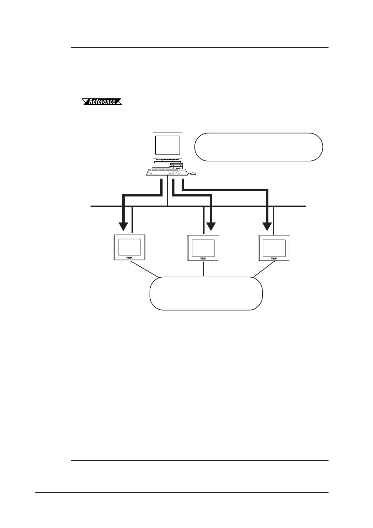
1.4.1 Ethernet Connectivity
The GLC2300 Series units can be connected to a LAN or an Ethernet compatible
PLC. The GLC2300 Series units also support the 2-way function.
This feature allows you to setup a GLC and to also perform screen data transfer.
You can even set up a completely new GLC via an Ethernet network.
For details about setting up the GLC via an Ethernet network, refer
to the GP-PRO/PB III for Windows Operation Manual (included in
the GP-PRO/PB III C-Package).
*1
Send all screen and system data to
your GLC via an Ethernet network
Ethernet
Assign an IP address to each
GLC, or set up a new GLC which
has no IP address settings.
1. Pro-face’s Pro-Server with Pro-Studio for Windows software (sold separately) is
required when using this feature.
GLC2300 Series User Manual1–10
1.4.2 CF Card
Chapter 1 – Introduction
The new GLC2300 series unit allows you to use a CF Card. You can set up the GLC
or send screen data by saving backup data (all data necessary for GLC operation) in
the CF Card using the GLC unit’ s CF Memory Loader Tool feature. As with the Multi
Unit, the GLC2300 series unit includes all the following features:
• Read filing data from CF Card
• Write logging data to CF Card
• Read image data or sound data from CF Card
• Write Graph data or Alarm data to CF Card
• Back up screen data to CF Card
For details about creating/saving backup data (i.e., all necessary data
for GLC operation) and sending GLC data, refer to the
GP-PRO/PB III for Windows Operation Manual (included in the
GP-PRO/PB III C-Package). For details about the CF Memory
Loader Tool’s data upload and download, see 4.3 – “CF Memory
Loader Tool.”
When using the CF Memory Loader Tool, Digital’s GP077-CF20 (16MB)/
GP077-CF30 (32MB) Memory Card is required.
*1
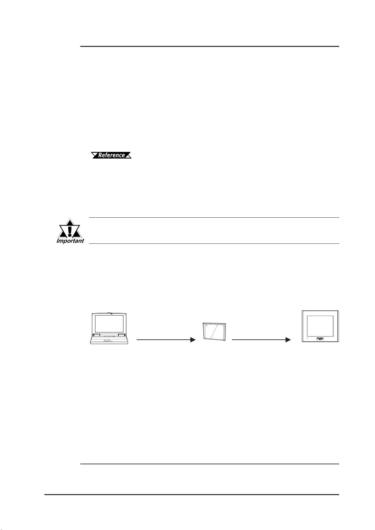
Send GLC Screen Data to a CF Card, then to Other GLCs
The CF Card allows you to set up multiple GLCs using a single GLC unit’s data.
Copy your GLC data and the CF Memory Loader Tool to your GLC unit’s CF
Card, then insert that CF Card in another GLC and transfer that data using the CF
Memory Loader Tool.
Copy data using the
GP-PRO/PB III
CF Card Tool
Transfer data to the GLC
via the CF Memory
Loader T ool
1. The setup is the sending of System and Protocol programs to the GLC via the screen
creation software, which allows you to use the GLC unit in the desired environment.
GLC2300 Series User Manual 1–11

Chapter 1 – Introduction
Send GLC Screen Data to a GLC, then to the CF Card
You can also use the GLC as a CF Card drive for your PC, by sending data from
your PC directly to your GLC unit’s CF Card. Connect your PC and the GLC
using the data transfer cable, and send your backup data and the CF Memory
Loader Tool to the CF Card installed in the GLC.
Send data using the GP-PRO/PB III for Windows’ Transfer feature
Transferring screen and system data to a GLC takes approximately thirteen minutes (approximately 6.5 MB) at a transmission speed of 115.2 kbps.
Send Data from a GLC to a CF Card, then to Another GLC
The CF Card allows you to use backup data saved in a GLC for setting up another
GLC. First, upload (transfer) your GLC unit’s backup data to your CF Card. Next,
remove the CF Card, insert it in a different GLC and download (transfer) the CF
Card’s data to that GLC. Be sure that the CF Memory Loader Tool is saved on the
CF Card prior to using this method.
Upload data via
“CF Memory
Loader Tool”
Download data via
“CF Memory
Loader Tool”
1.4.3 Expansion Serial Interface
The Expansion Serial Interface allows you to connect a bar-code reader, a 2-D
code reader, or other type of I/O device. It enables the input/output of large volumes of data which cannot be handled with a conventional bar code reader interface.
Also, connecting an I/O device requires the creation of a data transfer protocol
(via the D-Script feature).
Refer to the GP-PRO/PB III for Windows Operation Manual (included in the GP-PRO/PB III C-Package).
Bar Code Reader
I/O Device
Expansion
Serial I/F
Serial I/F
GLC2300 Series User Manual1–12
Chapter 1 – Introduction
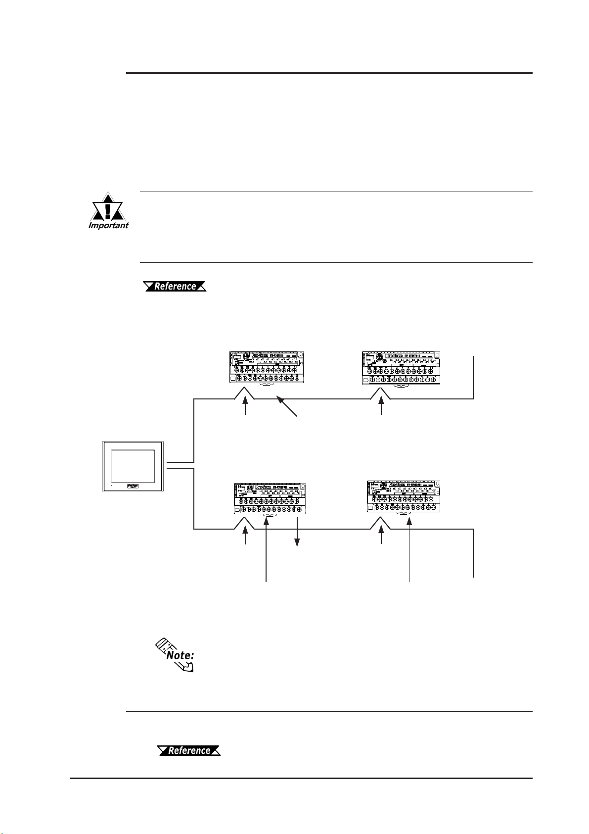
1.4.4 Flex Network Communication Interface
The following information explains how to connect the GLC to a Flex Network
Communication I/F and I/O Unit.
When connecting the I/O unit, 2 lines are available — CH1 and CH2. Each channel outputs the same data and either can be used for data transmission.
The maximum number of connectable units, when using a single channel, is 31,
and when using a second channel, the number increases by 32 to a total of 63.
The Flex Network uses high-speed data-transfer technology, and if a
cable that is not recommended in this document is used for data transfer, network data-transfer performance cannot be guaranteed. Therefore, use only the cable(s) recommended here.
Refer to the Flex Network User Manual (sold separately).
Standard System Design
GLC
16 Input Points
DC 24V
8 points Input /
8 points Output
DC 24V
Actuator Lamp
Sensor
Operation
Switch
Sensor
Operation
Switch
Valve
8 Points –
Relay Output
DC 24V
16 Input points
DC 24V
Sensor
Operation
Switch
to next station
to next station
*1
*1
6 Mbps is the recommended communication speed.
1. Be sure the Terminal Switch (TERM) of the network’s last unit (at each end) is
turned ON.
Refer to the Flex Network User Manual (sold separately).
GLC2300 Series User Manual 1–13

Chapter 1 – Introduction
1.4.5 Serial Device / Tool Connector Interface
Serial I/F
This interface is used to connect RS-232C and RS-422 interface cables to a host
(PLC).
See 2.3.1 – “Serial I/F.”
Tool Connector
This interface is used to connect a data transfer cable, a bar-code reader, or the
Memory Loader II unit to the GLC2300.
See 3.3 – “Tool Connector.”
1.4.6 2–Port Feature
The 2-Port feature allows you to use Mitsubishi’s GPP software package (ladder
programming software) on your PC while the GLC is connected to a PLC. With a
GLC2300 Series unit, you can use the 2-Port feature in the following two ways:
• With the Internal 2-Port Feature:
The GLC unit’s Tool Connector and a PC are connected via a data transfer cable (GPWCB02).
• With the External 2-Port Adapter II:
Pro-face’s 2-Port Adapter II (GP070-MD11) is used.
For information about PLC types and GLC compatibility with
GLC2300 Series units, refer to the GP-PRO/PB III for Windows
Device/PLC Connection Manual (included in the GP-PRO/PB III
C-Package).
When Using Internal 2-Port feature
*1
GLC
Connect to the
Serial I/F via the
Programmer I/F Cable
Connect to the
PLC’s
Programming Port
Connect to the GLC unit’s
Tool Connector via Data
Transfer Cable (GPW-CB02)
PC with Mitsubishi’s
GPP software installed
(Mitsubishi PLC compatible types only)
1. The Device Monitor feature can also be used at the same time.
For details about the device monitor function, refer to the
GP-PRO/PB III for Windows Device/PLC Connection Manual
(included in the GP-PRO/PB III C-Package).
GLC2300 Series User Manual1–14

Chapter 1 – Introduction
Internal 2-Port Feature Usage Notes
• To use the internal 2-port feature, you will need to adjust your GLC unit’s
settings.
For information about these settings, refer to the GP-PRO/PB III
for Windows Device/PLC Connection Manual (included in the
GP-PRO/PB III C-Package).
• This feature can be used only while the GLC is in ONLINE mode.
• Since the internal 2-port feature uses the GLC unit’s single tool connector, you
will not be able to use equipment which requires the tool connector (such as a
bar-code reader, optional items).
• If you transfer screen data while the GLC is in ONLINE mode, the screen will
not change to the data transfer screen automatically. Thus, you will need to
change the screen manually to the OFFLINE mode’s [Main Menu | Transfer]
screen.
See 4.1 – “Serial Data Transfer.”
• Peripheral equipment, such as a Programming Console, is not compatible with
the GLC unit’s internal 2-port feature. To use this type of equipment, you will
need to use the external 2- Port Adapter II.
When Using the External 2-Port Adapter
*1
GLC
Connected to GLC unit’s Serial I/F
Pro-face’s 2-Port Adapter II (GP070-MD11)
Connect to
Programming
Port
or
Mitsubishi PLC
(compatible
types only)
PC with Mitsubishi’s
GPP software installed
Programming
Console
1. GLC2300 Series units can also use the 2-Port Adapter II.
For details, refer to the GP-PRO/PB III for Windows Device/PLC
Connection Manual (included in the GP-PRO/PB III C-Package).
GLC2300 Series User Manual 1–15

Chapter 1 – Introduction
1.4.7 Backlight Burnout Detection Feature
When the GLC unit’s backlight burns out, it will be automatically detected. The
GLC unit’s Status LED will alert you that the backlight is burned out so that you
can disable GLC Touch Panel Operation and prevent a possible GLC operation
error. When Backlight Burnout is detected the GLC unit’s Status LED will turn
orange. Also, the system data area’s Status bit10
For details about touch panel operation when the backlight burns
out, see 6.4.3 – “Touch Panel Settings.”
Since the GLC monitors current consumption to detect if the backlight
has burned out, in certain cases detection may not be possible.
Since a major logic program error has a higher priority than
backlight burnout, if this type of error occurs while backlight
burnout has been detected, the GLC unit’s Status LED will
change from orange to red.
In some cases, even though a backlight burnout has been
detected, the backlight may remain faintly lit. In this case,
change the backlight as quickly as possible.
*1
will turn ON.
1. When using the Direct Access method, bit +6 will turn ON. The using Memory Link
method, bit 11 will turn ON.
For details, refer to the GP-PRO/PB III for Windows Device/PLC
Connection Manual (included in the GP-PRO/PB III C-Package).
GLC2300 Series User Manual1–16
Chapter
2 Specifications
2.1 General Specifications
2.1.1 Electrical
1. General Specifications
2. Functional Specifications
3. Interface Specifications
4. Part Names and Functions
5. Dimensions
Rate d Vo ltage
Rated Voltage Range
Allowable Voltage Drop
Pow er Consumption
In-Rush Current
Voltage Endurance
Insu lation Resistance
DC 24V
DC 19.2V to DC 28.8V
10ms max.
22W max.
30A max.
AC 1000V 20mA for 1 minute (between charging and FG t erminals)
20MΩ or more at DC 500V (between charging and FG t erminals)
GLC2300 Series User Manual 2–1
Chapter 2 – Specifications
2
2
3
2.1.2 Environmental
Ambient Operating
Temperature
Storage Temperature
Opera ting Humi dity
Storage Humidity
Air P u r ity (Dust)
Poll ution Degree
C orr osiv e Gasses
Atmosphe ric Endurance
(GLC Opera tion Altitude )
Sho ck Resist a nce
Vibra tion Re sistance
Noise Im munity
(via noise simulator)
Electrosta ti c Di scharge
Immunity
0oC t o +50oC*
1
-20oC t o +60oC
10%RH t o 90%RH
o
(non-condensing, wet bulb temperature: 39
C max.)
10%RH t o 90%RH
(non-condensing, wet bulb temperature: 39oC max.)
0.1mg/m
max. (non-conductive levels)
Pollution Degree 2
Fre e of corrosive g asses
800hPa to 1,114hPa (2000 meters max.)
IEC61131-2 (JIS B 3501) compliant
2
147m/s
Release time 11ms
three t i mes for each (X, Y, Z) directi on
IEC61131-2 (JIS B 3501) compliant
When Vibration is NOT Cont i nuous
10Hz to 57Hz 0.075mm, 57Hz to 150Hz 9.8m/s
When Vibration is Continuous
10Hz to 57Hz 0.035mm, 57Hz to 150Hz 4.9m/s
10 ti mes (80 min.) for each (X, Y, Z) directi on
Noise Voltage: 1000Vp-p, Pulse Duration: 1µs
Rise Time: 1ns
Contact Discharge Method 6kV
(complies with IEC 61000-4-2 Level 3)
1. When the GLC2300L operates for a long time in ambient temperatures that are
greater than 40
° C, crystal liquid may become temporarily unclear. The crystal liquid
will return to normal, and no operation problems should occur as a result.
2.1.3 Structural
Grounding
Ratings
External Dim ensi ons
Weight
Cooling Me thod
*1
1. The front face of the GLC is installed in a solid panel. The GLC unit’s level of resistance
and the conditions it has been tested under are equivalent to the standar ds listed in the
specifications. Oils that should have no effect on the GLC can harm the unit — when
vaporized oils are pr esent, when low-viscosity cutting oils are allowed to adhere to the
unit for a long time, or if the protective sheet on the fr ont face of the GLC peels off. These
conditions can lead to the ingress of oil into the GLC, and alternate pr otective measures
are suggested. To prevent deformation or corrosion of the front panel’s plastic cover due
to the presence of non-appr oved oils, confirm the operating environment conditions prior
to installing the GLC. If the installation gasket is used for a long time, or if the unit and its
gasket are r emoved from the panel, the original level of the protection cannot be guaranteed. To maintain the original protection level, replace the installation gasket r egularly.
100Ω max., or your country's applicable standard
Equivalent to IP65f (JEM 1030)
NEMA#250 Type4X/12
W171mm x H138mm x D60mm [6.73 in.x 5.43 in. x 2.36 in.]
1.2 kg [2.65 lb] max.
Na tural air circulation
GLC2300 Series User Manual2–2

Chapter 2 – Specifications
2.2 Functional Specifications
2.2.1 Display
GLC2300L GLC2300T
Type
Resolution
Effe ctive Display Area
Colors
Monochrome LCD TFT type color LCD
320 x 240 pixels
W115.2mm x H86.4mm
[4.54 in. x 3.40 in.]
Black and White,
2 levels of gray/
Black and White,
8 levels of gray
*1
64 colors/3-speed blink
(Color switching is done via
(Color switching is done via
soft ware)
256/No blink
soft ware)
*2
CCFL (Service life: 50,000 hrs. or
more at 25oC and 24-hour
operation) Not user replaceable.
Backlight
Contrast control
Brightness Control
CCFL (Service life: 50,000 hrs. or
o
more at 25
C and 24-hour
operation)
8 levels of adjustment available
via touch panel.
Four (4) levels of adj ust ment available via touch panel.
ASCII: (Code page 850) Alphanumeric (incl. Eur. characters)
Chinese: (GB2312 – 80 codes) simplified Chinese fonts
Language Fonts
Japanese: ANK 158, Kanji: 6962 (JIS Standards 1 & 2)
Korean: (KSC5601 – 1992 codes) Hangul fonts
Taiwanese: (Big 5 codes) traditional Chi nese f onts
Displ ay S izes
Font Sizes
8x8 dots
Text
8x16 dots
16x16 dots
32x32 dots
*3
8X8 dot font, 8X16 dot font, 16X16 dot f ont and 32X32 dot font
Height can be expanded 1 to 8 times.
*4
Width can be expanded 1/2
, 1 to 8 times.
40 char. x 30 rows
40 char. x 15 rows
20 char. x 15 rows
10 char. x 7 rows
1. In order to set the monochrome (eight levels of gray) mode, GP-PRO/PB III for
Windows Ver.6.2 or later is required. Depending on the color used, selecting MONOCHROME 8 HUES may cause the GLC unit’s screen to flicker and make it difficult to
distinguish colors. Confirm that all colors display as expected prior to using this
mode.
2. Changing the Colors setting to “256 colors” will disable the blink feature on all
screens in your project. If you wish to use the blink feature, do not change this setting
to “256 colors.”
3. The display font will differ depending on the character (language) or size you select.
4. Only available when using “Half-2 Byte Character” settings via software.
(Only Chinese, Taiwanese, and Korean OS)
GLC2300 Series User Manual
See 6.8 – “SET UP SCREEN.”
2–3

Chapter 2 – Specifications
p
2.2.2 Memory
Application
Data Backu
2MB FLASH EPROM (approx. 640 screens at 3.2KB/screen)
256KB SRAM (uses lithium battery)*
2.2.3 Control Memory
Variable Area
Program Area
• Refer to Pro-Control Editor manual for SRAM (size) usage
details.
• 128KB of SRAM is reserved for the Online Editor.
1. A Lithium battery’s lifetime is:
• 10 years when the battery’s ambient temperature is 40
• 4.1 years when the battery’s ambient temperature is 50
• 1.5 years when the battery’s ambient temperature is 60
When used for backup: (without main power)
• Approximately 60 days, with a fully charged battery
• Approximately six (6) days, with a 10% charged battery
SRAM Max. 64KB.
Lithium battery is used t o retain variable data
FLASH EPROM 128KB
1
o
C max.
o
C max.
o
C max.
*1
2.2.4 Resolution / Clock
Resolution
Clock Accuracy
The GLC unit’s internal clock has a slight error. At normal
operating temperatures and conditions, with the GLC operating from its lithium battery, the degree of error is 65 seconds
per month. Variations in operating conditions and battery life
can cause this error to vary from -380 to +90 seconds per
month. For systems where this degree of error will be a problem, the user should be sure to monitor this error and make
adjustments when required.
See 6.7 – “SET UP TIME.”
16 x 12 keys/screen (1 or 2 point touch)
±65 seconds/month (at room temperature)
GLC2300 Series User Manual2–4

2.2.5 Interfaces
Serial Interface
Expansion Serial Interface
Ethernet Interface
Tool Connector
Chapter 2 – Specifications
Asynchronous Transmission:
RS232C/RS422
Data Length: 7 or 8 bits
Stop Bit: 1 or 2 bits
Parity: None, Odd or Even
Data Transmission Speed: 2,400 to 115,200bps
Asynchronous Transmission:
RS232C
Data Length: 7 or 8 bits
Stop Bit: 1 or 2 bits
Parity: None, Odd or Even
Data Transmission Speed: 2,400 to 38,400bps
IEEE802.3, 10BASE-T
Asynchronous TTL level nonprocedural command I/F
<During screen file development>
Used for transferring data between the GLC application software and
the GLC. Used for data transfer with the 2-port feature.
<During Logic Program Development>
Used for transferring data between the Logic Program Development
software and the GLC.
<During RUN Mode>
Used for a variety of devices, such as bar-code readers and serial
printers.
CF Card Interface
Screw Lock
Terminal Block
(Flex Network
Communication Interface)
1 slot
Communication Style: 1:N
Connection Format: Multi-Drop Connection
Communication Range: 200m/CH at 6Mbps, 100m/CH at 12Mbps
Communication Format: Cyclic Data Transfer, Half-duplex
Communication Speed: 6Mbps, 12Mbps
Communication I/F: Differential method,
Pulse Transformer Insulation method
Error Check: Format Test, Bit Test, CRC-12 Test
Number of connection stations: 63 stations max.
Number of I/O points: 1008
GLC2300 Series User Manual
2–5
Chapter 2 – Specifications
2.3 Interface Specifications
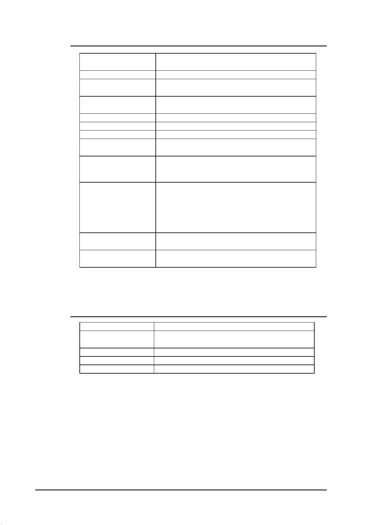
2.3.1 Serial Interfaces
This interface can be either RS-232C or RS-422. Connects GLC to Host (PLC).
This interface uses a socket-type connector.
Pin Assignments Pin # Signal Name Condition
SIO
1
14
25
13
1 FG Frame ground
2 SD Send data (RS-232C)
3 RD Receive data (RS-232C)
4 RS Request send (RS-232C)
5 CS Clear send (RS-232C)
6 DR Data Set Ready (RS-232C)
7 SG Signal ground
8 CD Carrier detect (RS-232C)
9 TRMX Termination (RS-422)
10 RDA Receive data A (RS-422)
11 SDA Send data A (RS-422)
12 NC No connection (Reserved)
13 NC No connection (Reserved)
14 VCC 5V±5% output 0.25A
15 SDB Send data B (RS-422)
16 RDB Receive data B (RS-422)
17 RI Ring Indicate (RS-232C)
18 CSB Clear send B (RS-422)
19 ERB Enable receive B (RS-422)
20 ER Enable receive (RS-232C)
21 CSA Clear send A (RS-422)
22 ERA Enable receive A (RS-422)
23 NC No connection (Reserved)
24 NC No connection (Reserved)
25 NC No connection (Reserved)
GLC2300 Series User Manual2–6

Chapter 2 – Specifications
Recommended Parts
Connector Dsub25pin plug XM2A-2501 (OMRON)
Cover Dsub25pin cover XM2S-2511 (OMRON)
Dsub25pin cover XM2S-2521 (OMRON)
Jack Screws XM2Z-0071 (OMRON)
Cable CO-MA-VV-SB5PX 28AWG (Hitachi Cable Ltd.)
Use rough metric type M2.6x0.45 p threads used to secure
the cable’s set screws.
To confirm your PLC unit’s connection specifications, refer to the
GP-PRO/PB III for Windows Device/PLC Connection Manual (included in the GP-PRO/PB III C-Package).
Use the following instructions to create your own cable:
With an RS-422 cable:
• The following pins must be shorted as follows:
#18 (CSB) #19 (ERB)
#21 (CSA) #22 (ERA)
• Connecting the RS-422 cable’s #9 (TRMX) and #10 (RDA)
pins inserts a termination resistance of 100W between
#10 (RDA) and #16 (RDB).
• When making a cable for a Memory Link system, use a
4-wire type cable.
With an RS-232C cable:
• Do NOT use the following pins:
#9 (TRMX), #10 (RDA), #1 1 (SDA), #15 (SDB), #16 (RDB),
#18 (CSB), #19 (ERB), #21 (CSA), #22 (ERA)
• Connect the #1 (FG) terminal only if it is required by a connected device.
• This GLC unit’s serial port is not isolated. When the host (PLC) unit is
also not isolated, and to reduce the risk of damaging the RS-422 circuit, be sure to connect the #7 SG (Signal Ground) terminal.
• Pin #14 (VCC) DC 5V Output is not protected. To prevent damage or
unit malfunction, use only the designated level of current.
GLC2300 Series User Manual
2–7
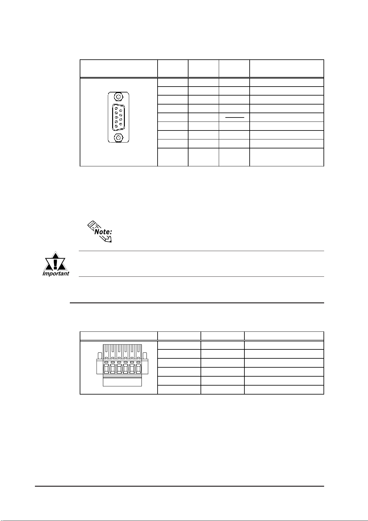
Chapter 2 – Specifications
Expansion Serial Interface
This interface is used for RS-232C data transfer, and uses a plug-type connector.
Pin Assignme nts Pi n No.
1 CD Input Carrier det ect (RS-232C)
2 RD Input Receive data (RS-232C)
5
1
9
6
3 SD Output Send dat a (RS-232C)
4 ER Output Enable receive (RS5 SG Signal Ground
6 DR Input Data Set Ready (RS7 RS Output Request Send (RS8 CS Input Clear send (RS-232C)
9RI/VCC
Signal
Name
Signal
Direction
Input/
Output
Recommended Parts
Connector Dsub 9pin socketXM2D-0901 (OMRON)
Cover Dsub 9pin cover XM2S-0913 (OMRON)
Jack Screws XM2Z-0073 (OMRON)
Use inch type set screws (#4-40 UNC).
Condition
Ring Indicate (RS-232C)
+5V+5% 0.25A
Pin #9 (VCC) DC 5V Output is not protected. To prevent damage or unit
malfunction, use only the designated level of current.
2.3.2 Flex Network Communication Interface
Screw Lock Terminal Block
This interface is used for Flex Network.
Pin Assignments Pin No. Signal Name Condition
1 TR+ CH1 Communication Data
2 TR- CH1 Communication Data
3 SLD CH1 Cable Shield Line
4 TR+ CH2 Communication Data
5 TR- CH2 Communication Data
16
6 SLD CH2 Cable Shield Line
GLC2300 Series User Manual2–8

Chapter 2 – Specifications
2.4 Part Names and Functions
A: Display Panel
The GLC monitor screen displays usercreated screens and corresponding host
(PLC) data.
GLC2300L Monochrome LCD
GLC2300T TFT type color LCD
B: Touch Panel
Enables the user to perform screen
change operations or input data.
C: Status LED
Indicates the GLC unit’s current condition.
A,BC
Front
Color Indicator
Green ON OFFLINE ---
ON In operation RUN
Flashing In operation STOP
Red ON In operation Major Error
Color Indicator
Orange ON
D: Power Input Terminal Block
Connects Power Cord.
E: Expansion Unit Interface (EXT)
Connects a data communication unit to
the GLC unit.
F: CF Card Access LED
If the CF Card Cover is closed when the
CF Card is inserted, the LED lamp turns
ON. The LED lamp will remain ON, even
if the CF Card Cover is opened while the
GLC accesses the CF Card.
Operation
Mode
Des cription
Backlight burnout has occurred.
D
Controller
Operation Mode
F
Rear
E
GLC2300 Series User Manual
2–9
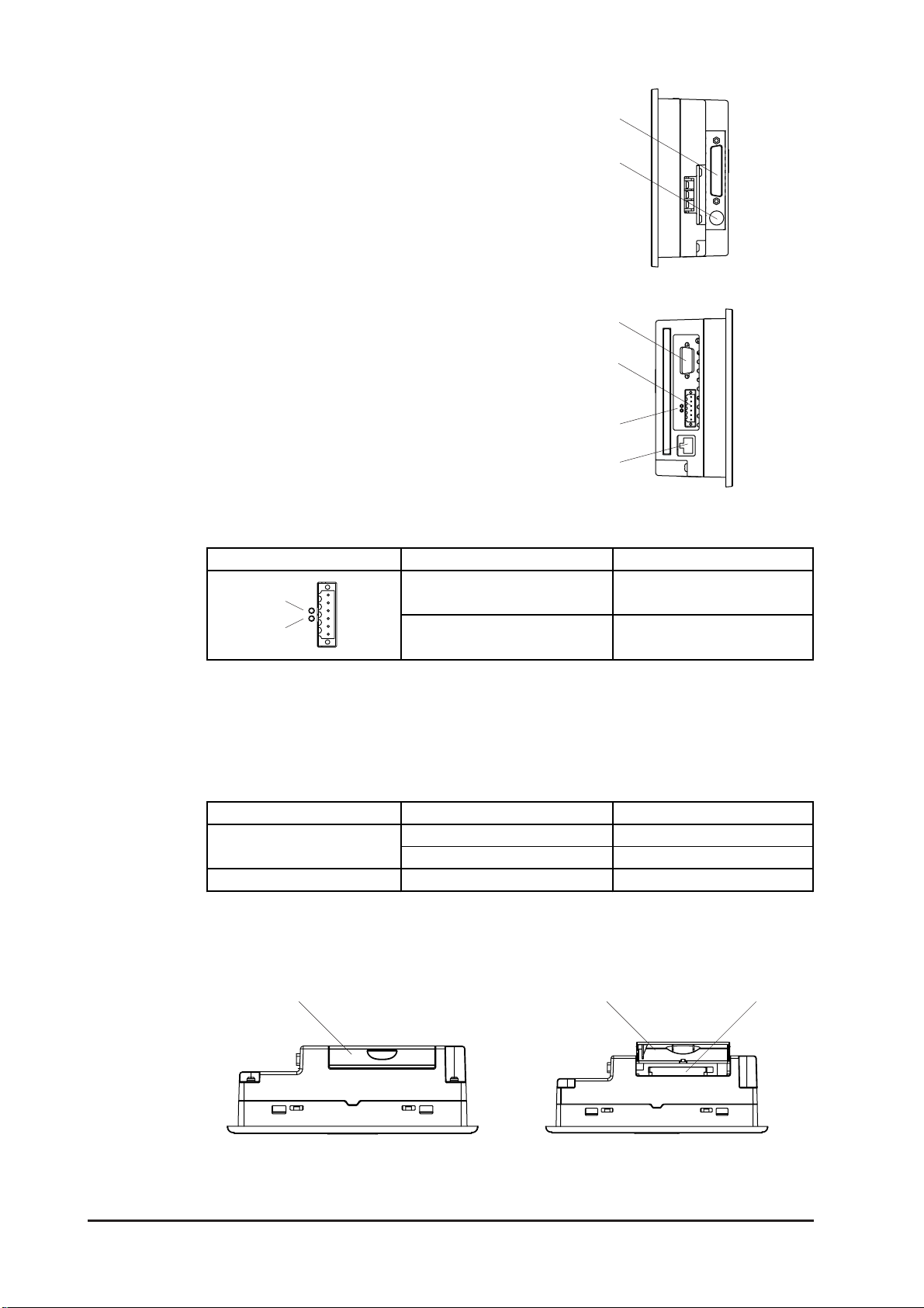
Chapter 2 – Specifications
y
G: Serial Interface (COM1)
RS-232C/422 Interface (Dsub 25-Pin).
Connects to a host (device/PLC) or a temperature controller.
H: Tool Connector (TOOL)
Connects to Transfer Cable, Bar Code
Reader, Serial Printer.
G
H
Right
I: Expansion Serial Interface (COM2)
RS-232C Interface (Dsub 9-Pin).
J: Screw Lock Terminal Block (Flex
Network)
Flex Network Interface.
K: Flex Network Interface
Flex Network I/F status LED will turn ON
or flash, according to the unit’s status.
LED Status Description
a
b
a: RUN (Green)
b: ERR (Red)
L: Ethernet Interface (10BASE-T)
Used for Ethernet (10BASE-T).
The LED will change (turn ON, blink)
according to the GLC unit’s status.
I
J
K
L
Left
Turns on when
Communication is enabled.
Turns on when failure occurs
in connected I/O Unit.
Status LED Displa
Orange
Green ON Link
M: CF Card Cover
N: CF Card Slot
MMN
Bottom CF Cover Open
Description
ON Power ON
Flash Send/Receive
GLC2300 Series User Manual2–10

2.5 Dimensions
2.5.1 GLC2300 External Dimensions
Unit: mm [in.]
155.5 [6.12]
Top
Chapter 2 – Specifications
171 [6.73]
Front
5 [0.20]
138 [5.43]
60 [2.36]
123 [4.84]
Side
GLC2300 Series User Manual
2–11

Chapter 2 – Specifications
The following diagram shows the GLC2300 Series unit’s connecting cables.
Unit: mm [in.]
A
24
[0.94]
61 [2.40]
C
D
9
[0.35]
Interface Display Description
A
B
C
D
E
COM1 Multi -link Cable GP230-ISI2-0
TOOL Data Transfer Cable GPW-CBO2
COM2 RS-232C Cable Commercial type
Flex Network Flex Network Communication Cable FN-CABLE2010-31-MS
10BASE-T
Ethernet
10BASE-T
Ethernet Cable
2.5.2 Installation Fasteners
Unit: mm [in.]
M5
31 [1.22]
19.5 [0.77]
B
35
[1.38]
37
[1.46]
E
Commercial type
16 [0.63]
φφ
φφ
φ10 [0.39]
11 [0.43]
GLC2300 Series User Manual2–12

Chapter 2 – Specifications
The following diagram shows when the installation fasteners are connected to the
GLC2300 Series unit.
Unit: mm [in.]
136 [5.35]
123 [4.84]
146 [5.75]
16 [0.63]
138 [5.43]
16 [0.63]
171 [6.73]
126 [4.96]
16 [0.63]
16 [0.63]
100 [3.94]
60[2.36]
2.5.3 Panel Cut Dimensions
Unit: mm [in.]
+1
156
Panel
0
[6.14 ]
5[0.20]
+0.04
0
155.5 [6.12]
4-R3 (max.)
0
0.04
[4.86 ±
1
0
Panel
]
GLC2300 Series User Manual
123.5 ±
Allowable Panel thickness
1.6 [0.06] to 5.0 [0.20]
2–13

Memo
GLC2300 Series User Manual2–14
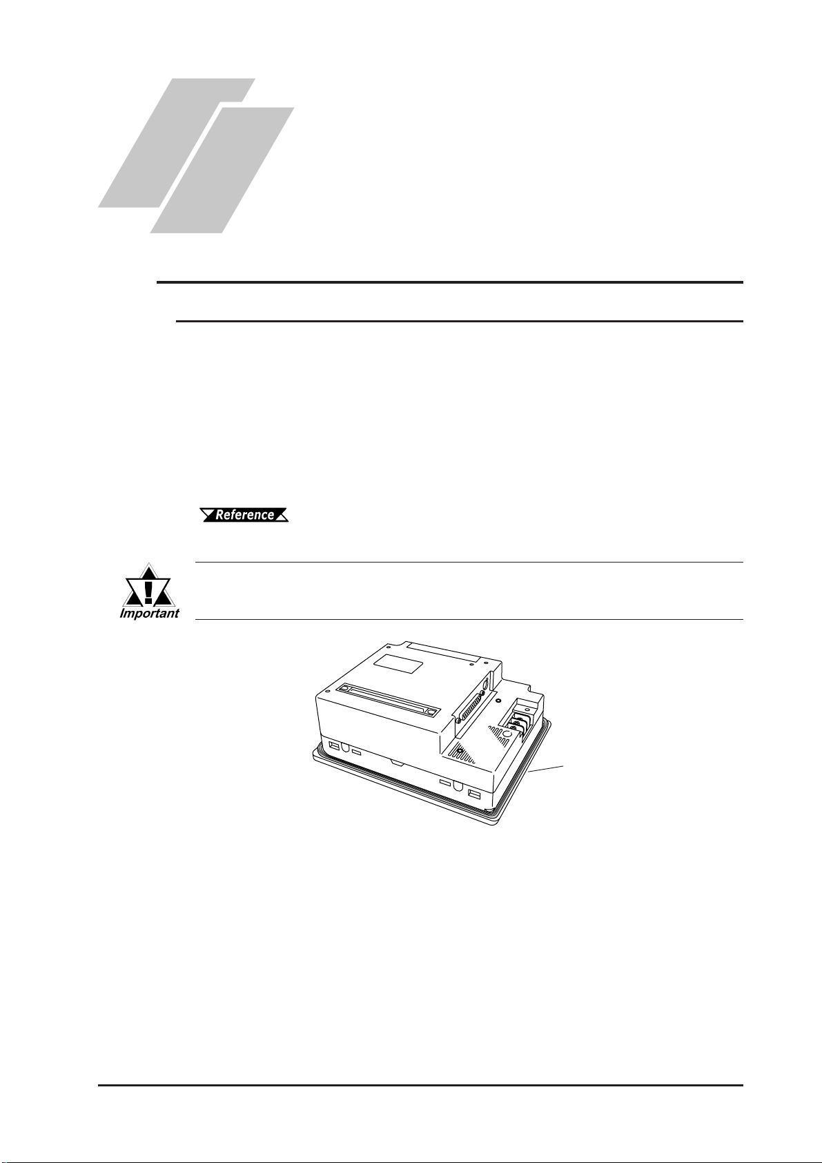
1. Installation
2. Wiring Cautions
3. T ool Connector
Chapter
4. Ethernet Cable Connector
3 Installation and Wiring
3.1 Installation
3.1.1 Installation Procedures
Follow the steps in this section to install the GLC.
Attaching the Installation Gasket
Pro-face strongly recommends that you use the installation gasket to absorb vibration as
well as repel water.
Place the display panel of the GLC face down on a level surface. Make sure that the
GLC unit’ s installation gasket is securely fitted into the groove that runs around the
perimeter of the panel’s frame.
5. CF Card Insertion and
Removal
6. Flex Network Communication Cable
For details about installing the gasket, see 8.1.2 – “Installation Gasket Check/Replacement.”
Before installing the GLC into a cabinet or panel, check that the Installation gasket is securely attached to the unit.
Installation
Gasket
3–1GLC2300 Series User Manual

Chapter 3 – Installation and Wiring
Creating a Panel Cut
Create an opening with the correct dimensions to install the GLC.
For the correct installation dimensions, see 2.5.3 – “GLC Panel Cut
Dimensions.”
The installation gasket, installation fasteners, and attachment screws are all required
when installing the GLC.
Panel
Panel Cut
Area
Make sure that the installation panel or cabinet’s surface is
flat, in good condition, and has no jagged edges. Metal reinforcement strips can also be attached to the inside of the
panel, near the Panel Cut, to increase the panel’s strength.
Panel thickness should be between 1.6 mm and 5.0 mm (0.06 in. and
0.20 in.), and should be based on the strength required to mount the
GLC to the panel.
1.6 mm to 5.0 mm [0.06 in. to 0.20 in.]
For easier maintenance and operation, and improved ventilation, install the GLC at least 100 mm (3.94 in.) away from adjacent structures
and other equipment.
Unit: mm [in.]
100
[3.94]
100
[3.94]
100
[3.94]
100
[3.94]
100
[3.94]
100
[3.94]
100
[3.94]
3–2 GLC2300 Series User Manual
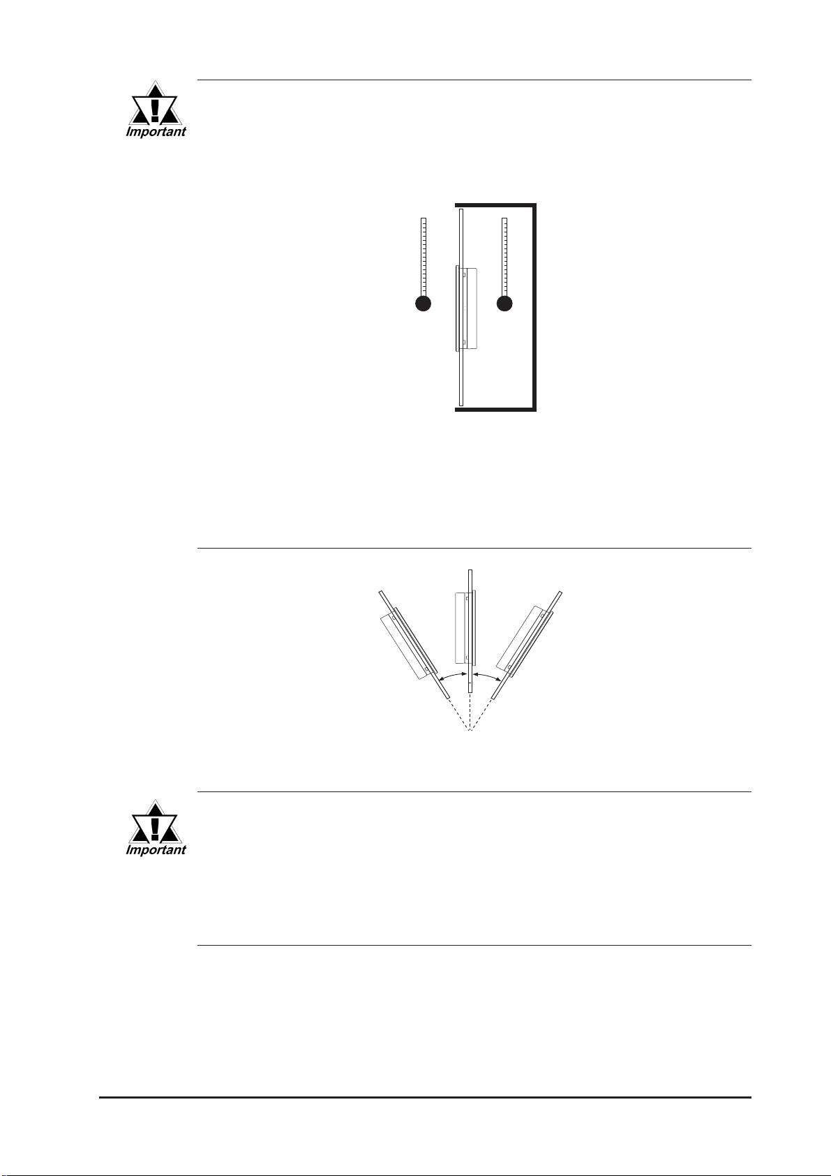
Chapter 3 – Installation and Wiring
• Make sure that the ambient operation temperature and the ambient
humidity are within their respective, designated ranges. (When installing the GLC in a cabinet or enclosure, the term “ambient operation temperature” indicates the cabinet or enclosure’s internal temperature.)
Cabinet
Enclosure
• Make sure that heat from surrounding equipment does not cause
the GLC to exceed its standard operating temperature.
• When installing the GLC in a vertically-inclined panel, the panel’s
face should NOT incline more than 30o.
Less than 30o from vertical
• When installing the GLC in a vertically-inclined panel, and the panel’s
face inclines more than 30
ceed 40
sure the ambient operating temperature is lower than 40
• When installing the GLC vertically, position the unit so that the Power
Input Terminal Block is also vertical.
GLC2300 Series User Manual
o
, the ambient temperature must NOT ex-
o
C. You may need to use forced air cooling (fan, A/C) to en-
o
C.
3–3

Chapter 3 – Installation and Wiring
Installing the GLC
1. Insert the GLC into the panel cut, as
follows:
2. Insert the installation fasteners into the
GLC unit’ s insertion slots — two slots
each, at the top and bottom of the unit
(4 slots total).
Installation Slots
3. Insert each of the fasteners, as follows:
4. Be sure to pull the fastener back until it is
flush with the rear of the attachment hole.
Installation Panel
Hook
3–4 GLC2300 Series User Manual
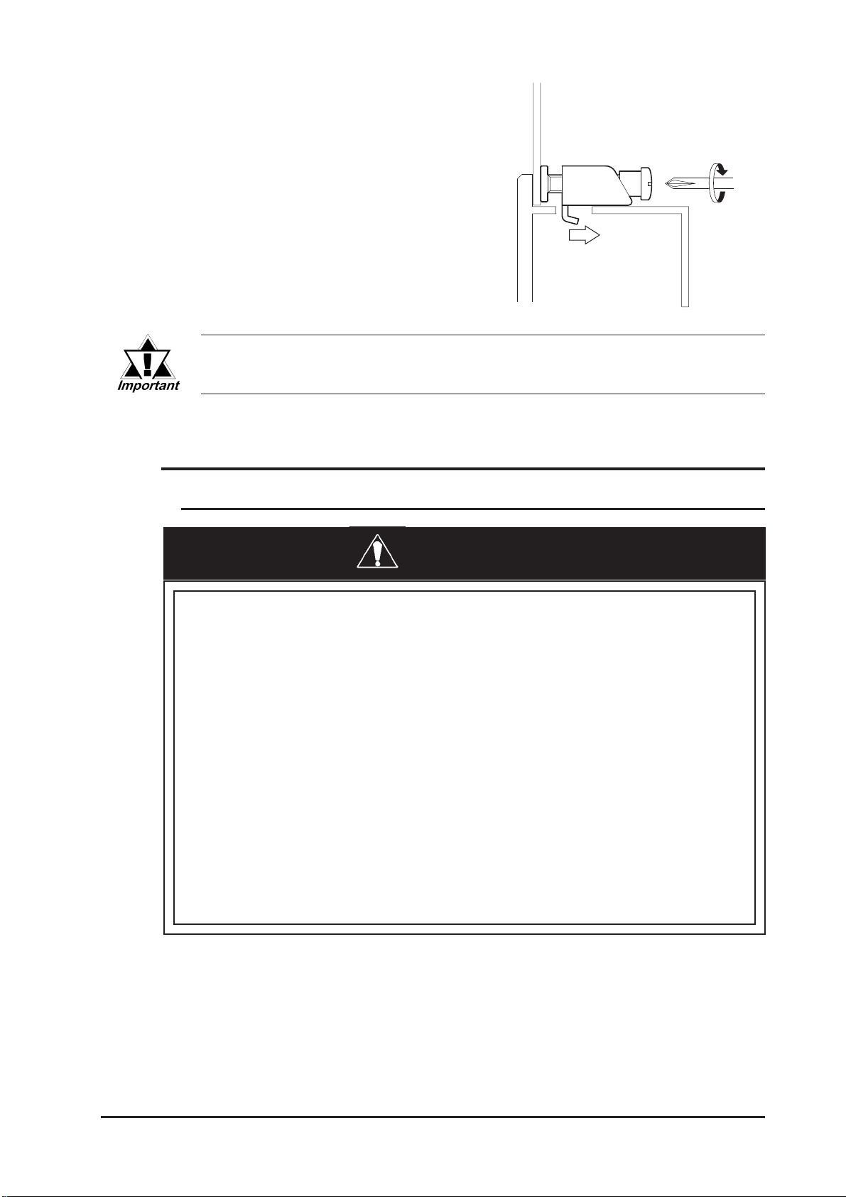
Chapter 3 – Installation and Wiring
5. Use a Phillips screwdriver to tighten
each fastener screw and secure the GLC
in place.
A torque of only 0.5 N•m is sufficient to tighten these screws.
Excessive force may damage the GLC unit.
3.2 Wiring Cautions
3.2.1 Connecting the Power Cord
WARNINGS
• To avoid an electric shock, be sure the power cord is
unplugged from the power supply when connecting the
power terminals to the GLC unit.
• Both the GLC2300-LG41-24V and the GLC2300-TC41-24V
use a DC 24V power supply. If the power supply is outside of the rated voltage range, both the power supply
and the GLC unit can be damaged.
• The GLC unit is not equipped with a power switch. There-
fore, be sure to connect a breaker-type power switch to
the GLC unit’s power cord.
• Be sure to connect the FG terminal to earth. Otherwise,
electrical shock may occur if the unit breaks down.
GLC2300 Series User Manual
3–5

Chapter 3 – Installation and Wiring
• To prevent the Ring Terminals from short-circuiting when the termi-
nal block attachment screws are loosened, use sleeve-type Ring T erminals.
• When the FG terminal is connected, be sure that the wire is grounded.
Not grounding the GLC unit will result in excessive noise. Use your
country’s applicable standard for grounding.
• The SG and FG terminals are connected internally in the GLC unit.
• When connecting the SG line to another device, be sure that the
design of the system/connection does not produce a shorting loop.
• Whenever possible, use thick wires (2mm2 max.) for power
lines, and twist the exposed wire ends when connecting
the Ring Terminals.
• Use the following crimp-on type Ring Terminals.
φφ
Over
φ3.2 mm [0.13 in.]
φφ
Under 6.0 mm
[0.24 in.]
Ring Terminal
Connecting the Power Supply Lines
GLC2300-LG41-24V/GLC2300-TC41-24V Unit
Power Input
Terminal Block
+
–
FG
Positive electrode
Negative electrode
Grounding Terminal connected to the GLC chassis.
3–6 GLC2300 Series User Manual

Chapter 3 – Installation and Wiring
T o connect the power supply lines:
1. Make sure the GLC unit’s power cord is not plugged in to the power supply .
2. Remove the Terminal Strip’ s clear plastic cover.
3. Remove the terminal attachment screws from the three (3) middle terminals, position
the Ring T erminals on the correct electrode, and reattach the screws.
See 3.2.2 – “Connecting the Power Supply.”
• Be sure that each Ring Terminal is connected to the correct termi-
nal.
• Use a torque of only 0.5 to 0.6 N•m to tighten the terminal attachment
screws.
4. Reattach the Terminal Strip’ s clear plastic cover .
3.2.2 Connecting the Power Supply
• When supplying power to the GLC unit,
separate the input/output and operation
unit lines (see Diagram 1).
• To increase the noise resistance quality
of the power cord, twist each power
wire before attaching the Ring T erminal.
• The power supply cord must not be
bundled or positioned close to main
circuit lines (high voltage, high current),
or input/output signal lines (see Diagram
2).
• Connect a lightning surge absorber (see
Diagram 3) to deal with power surges.
• To avoid excess noise, make the power
cord as short as possible.
• Ground the surge absorber
(E1) separately from the GLC
unit (E2).
Dia. 1
Dia. 2
Dia. 3
Main
power
Main
power
Input/
Output
power
Main circuit power
GLC
power
Input/
Output
power
GLC
power
GLC unit
I/O
device
GLC unit
I/O
device
I/O
device
Operation
unit
• Select a surge absorber with
a maximum circuit voltage that
is greater than that of the
power supply’s peak voltage.
GLC2300 Series User Manual
GLC unit
Lightning
surge
absorber
3–7
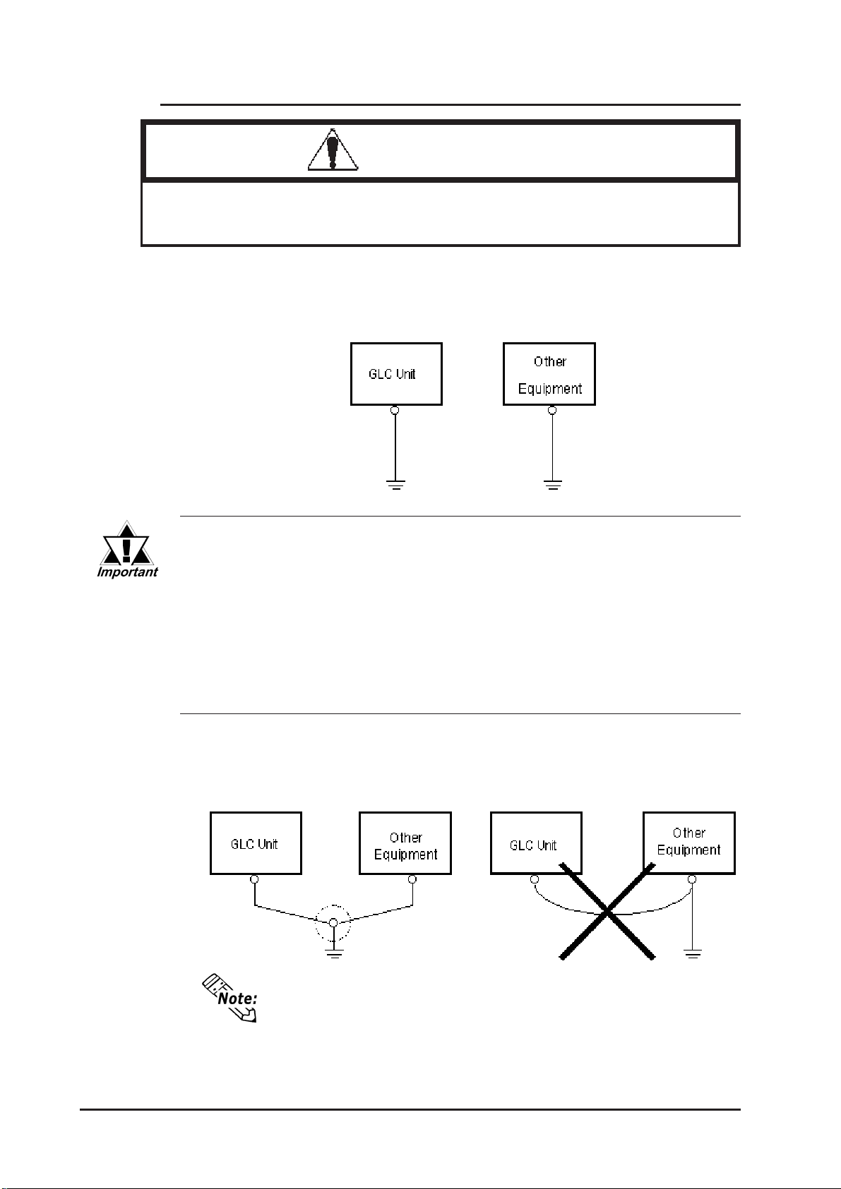
Chapter 3 – Installation and Wiring
3.2.3 Grounding
CAUTION
Do NOT use common grounding, since it can lead to an
accident or machine breakdown.
Connect the FG terminal found on the back of the GLC to an exclusive ground
(diagram A).
(A) Exclusive Grounding (BEST)
• Make sure that the grounding resistance is less than 100
• FG and SG terminals are internally in the GLC.
• When connecting the SG line to another device, be sure that the
design of the system/connection does not produce a shorting loop.
• The grounding wire should have a cross-sectional area of at least
2
2 mm
sible, and keep the wire as short as possible. Replace thin wire with
a thicker wire, and place it in a duct.
. Create the grounding point as close to the GLC unit as pos-
ΩΩ
Ω.
ΩΩ
If exclusive grounding is not possible, use a common connection point (diagram B).
(B ) Common Grounding (OK)
(C) Common Grounding (Not OK)
If the equipment does not function properly when grounded,
disconnect the ground wire from the FG terminal.
3–8 GLC2300 Series User Manual

Chapter 3 – Installation and Wiring
3.2.4 I/O Signal Line Cautions
To help prevent noise and interference problems, separate all communication lines
from power lines by placing them in a separate duct.
Duct for Power Lines
If different wires must be placed in the same duct, separate them with an earthed/
grounded divider.
Grounded
Separators
Duct
Comm.
Cables
Standard
Cables
Power
Cables
(non-conducting
resin/plastic)
Earth/Ground
When you are unable to separate the cables as shown above,
be sure to use shielded cable and create a ground from the
shield line.
3.2.5 Installation Cautions
A problem in the external power supply or a GLC unit failure can lead to operation failures, which can affect the entire system. As a preventive measure, be sure
to set up a protection circuit (such as an Emergency Stop, Protection Network,
Interlock, or System Design circuit) in areas where potential failures may occur.
Examples of protection circuits that ensure the system’s reliability include the
following:
■■
■ Failsafe Electrical Circuits
■■
When designing failsafe circuits, be aware of possible malfunctions resulting from
differences in the startup times of the control device connected to the GLC output
unit (especially the DC power supply), the GLC unit’s system, and the program.
When using a remote I/O, create a logic program to check the terminal status.
GLC2300 Series User Manual
3–9

Chapter 3 – Installation and Wiring
For example, connect an electrical voltage relay coil to the GLC output unit power
supply circuit and to any connected control devices’ power circuit, then connect
their contacts to the GLC input unit. Design the circuit so that it checks for an ON
signal from the electrical voltage relay using a logic program, then executes the
ladder program of the control device connected to the GLC output unit.
Input Voltage
The power supply must be DC 24V (between DC 20.4V and DC 28.8V).
Power Interruption
When a power supply interruption is 10 ms. or longer, the GLC unit’s power will
also be interrupted. Also, when a power interruption occurs, operation will stop
even while a command is being issued.
For example, if the power is cut while an FMOV command is sending data in 100word units, command execution will stop.
When designing a logic program, be sure to allow for the possibility of a power
interruption.
Emergency Stop Circuit
Do NOT send an Emergency Stop signal to the GLC, and do NOT use the GLC
unit’s internal software to process an Emergency Stop signal.
Be sure to create the Emergency Stop circuit outside the GLC (see below).
Power source
AC DC 24V
Output
Emergency Stop Button
B contact
GLC
Input
Controlled
System
3–10 GLC2300 Series User Manual

Chapter 3 – Installation and Wiring
Interlock Circuit 1
Create an interlock circuit outside the GLC (below), to control a motor’s forward/
reverse rotation circuit using a GLC or PLC connection.
Auxiliary B contact of electromagnetic
GLC
switch for motor reverse rotation
Motor rotation signal
(forward)
Electromagnetic switch for
motor reverse rotation
Auxiliary B contact of electromagnetic switch for motor rotation
After the GLC runs the program, the timing of the ON/OFF signals to an output device is carried out simultaneously .
For example, an electromagnetic switch for forward and reverse motor rotation could be turned ON and OFF at the same
time. Therefore, when the main contacts for the power circuits of both the forward and the reverse motor rotation are
turned ON and OFF at the same time, an R Phase and a
T Phase short circuit may occur. Use the above interlock, or a
mechanical interlock equipped with an electromagnetic switch,
when designing a forward/reverse rotation circuit.
Electromagnetic
switch for motor
rotation
Motor reverse
rotation signal
Interlock Circuit 2
If there is a possibility that a GLC failure could cause an accident, use an external
hardware device to include a failsafe element in the design of the interlock circuit.
For example, if the system first needs to stop the Travel Motor whenever the Unit
Travel Limit Switch is activated, include the Unit Travel Limit Switch in the GLC
input. The following circuit uses a hardware method to ensure that the Travel
Motor is stopped.
This applies to hardware. Do NOT rely on software to process the interlock design.
GLC
Unit Travel
Limit Switch
Travel Motor Control Signal
Travel Motor
Control Circuit
Emergency
Stop Switch
Directly input to Emergency
Stop Circuit in Control unit
Unit Travel
Limit Switch
GLC2300 Series User Manual
3–11
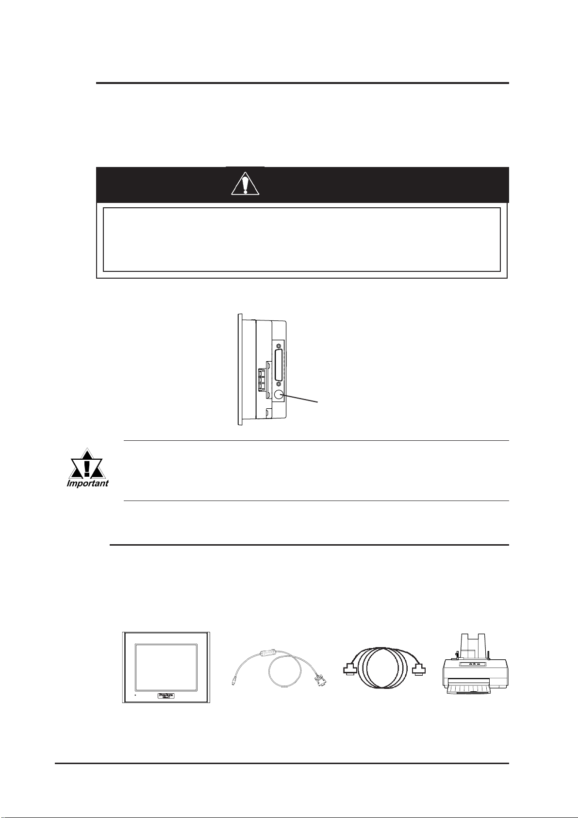
Chapter 3 – Installation and Wiring
3.3 Tool Connector
A data transfer cable or a bar-code reader can be attached to the GLC unit’s tool
connector. A serial printer can be connected with a data transfer cable and a usercustomized conversion cable. The location of the GLC unit’s tool connector is
shown in the following diagram.
WARNING
To prevent an electrical shock, unplug the GLC unit’s
power cord from the main power supply prior to attaching or detaching any connectors to or from the GLC.
GLC2300 Right Side
Tool Connector
When the Bar Code Reader uses a separate power supply:
• Turn the Bar Code Reader ON before turning the GLC ON.
• Turn the GLC OFF before turning the Bar Code Reader OFF.
3.3.1 Serial Printer Connection
Overview
The GLC unit outputs to a printer via the tool interface. Use the optional data
transfer cable to connect to the user-customized conversion cable, and connect
that cable to the serial printer's connector.
GLC
Data Transfer Cable Conversion Cable
(user-customized)
3–12 GLC2300 Series User Manual
Serial Printer

Chapter 3 – Installation and Wiring
GP System Setup
You can use the screen creation software to send printer output to the tool interface in the GP System Setup | I/O Settings menu. In the Printer settings area, select
the Tool Connector item in the Printer Port setting area. Depending on the connected serial printer, the Type setting and the Keyboard SIO Baud Rate setting will
differ.
Data Transfer Cable (Dub 9-Pin) Specification
The data transfer cable (Model: GPW-CB01) uses a socket-type connector. The
cable’s pins are assigned as follows:
Pin Assignments Pi n No. Signal Name
1DTR
1
5
Use inch type set screws (#4-40 UNC).
6
9
2TXD
3RXD
4DSR
5GND
6RTS
7CTS
8RTS
9
GLC2300 Series User Manual
3–13

Chapter 3 – Installation and Wiring
HP Laser Jet 4PJ Printer
Conversion Cable Wiring Diagram
(Dsub 9-Pin)
Pin No. Signal Name Pin No. Signal Name
1DTR 1
2TXD 2 TD
3RXD 3 RD
4 DSR 4 DSR
5 GND 5 GND
6 RTS 6 DTR
7CTS 7
8 RTS 8 DTR
99
Printer Type Settings Area – Type and Keyboard SIO Baud Rate
PrinterData Transfer Cable
T ype: HP Laser Jet II
Keyboard SIO Baud Rate: 9600bps
Printer Settings
Se rial Me nu PCL Me nu Job Menu
Serial
Protocol
Ba u d R ate
RobustXon
DTR Pol ari ty
RS-2332
Xon/Xoff
9600
OFF
HI
Font Source
Font No.
Size
Symbol
I (build-in)
1
12
WIN3.1
Resolution
Serial
Timeout
600
PCL
15
Available Printout Features
The printout features available with the GLC2300L/GLC2300T unit are as follows:
Printout Features
Japanese I-ASCII Korean / Taiwanese / Chinese
Screen Hard Copy O O O
Print Alarm Message O O O
Real-time print of Q Tag alarm O O O
Batch print of Q Tag alarm O O O
Print Log Data (Single Block) O O O
NADA Electronics TP-651G Printer (ver. 1.3)
Conversion Cable Wiring Diagram
Pin No. Signal Name Pin No. Signal Name
1DTR 1 FG
2TXD 2 SD
3RXD 3 RD
4DSR 4RTS
5GND 5CTS
6RTS 6DSR
7CTS 7 SG
8RTS 20DTR
9
Availability
Printe rDa ta Tr ansfer Cabl e (Dsub 9-P i n )
3–14 GLC2300 Series User Manual

Chapter 3 – Installation and Wiring
Printer Type Settings Area – Type and Keyboard SIO Baud Rate
Type: Epson (High Quality)
Keyboard SIO Baud Rate: 19200bps
Printing Method: monochrome
Printer Settings
DIP SW1
Switch Feature ON/OFF
SW1-1 LISTER P PRINT OFF
SW1-2 Buffer Full Print OFF
SW1-7 Graphic Double Height Printing ON
SW1-8 Exclusive Graphic 800 x 600 dot printing OFF
DIP SW2
Switch Feature ON/OFF
SW2-1 ON
SW2-2 ON
SW2-3 Data Bit Length: 8 bits OFF
SW2-4 Parity: Invalid OFF
SW2-5 Parity: EVEN OFF
SW2-6 Stop Bit: 1 bit OFF
SW2-7 XON/XOFF TYPE ON
SW2-8 Print Interval: 1 second OFF
Baud Rate: 19200bps
Available Printout Features
The printout features available with the GLC2300L/GLC2300T unit are listed as
follows:
Printout Features
Japanese I-ASCII Korean / Taiwanese / Chinese
Screen Hard Copy O O O
Print Alarm Message O O O
Real-time print of Q Tag alarm O O O
Batch print of Q Tag alarm O O O
Print Log Data (Single Block) O O O
EPSON TM-U210PD Printer
Conversion Cable Wiring Diagram
(Dsub 9-Pin)
Pin No. Signal Name Pin No. Signal Name
1DTR
2TXD 2TXD
3RXD 3RXD
4DSR 4RTS
5GND 7GND
6RTS 20DTR
7CTS
8RTS
9
Availability
PrinterData Transfer Cable
GLC2300 Series User Manual
3–15

Chapter 3 – Installation and Wiring
p
p
Printer Type Settings Area – Type and Keyboard SIO Baud Rate
Type: EPSON (High Quality / High Speed)
Keyboard SIO Baud Rate: 9600bps
Printer Settings
DIP Switch Set 1
Switch Function ON/OFF
SW1-1 Data reception error Prints"?"
SW1-2 Receive buffer capacity Approx. 1K bytes
SW1-3 Handshaking XON/XOFF
SW1-4 Word length 8bits
SW1-5 Parity check No
SW1-6 Parity selection Odd
SW1-7 Baud rate 9600bps
SW1-8 Busy condition Sets the printer to BUSY
DIP Switch Set 2
Switch Function ON/OFF
SW2-1 Print column selection 7x9 font / 9x9 font 40/33
SW2-2
SW2-3
SW2-4
SW2-5
SW2-6
SW2-7 I/F
SW2-8 I/F
Internal use. Setting must not be changed (set to OFF).
Internal use. Setting must not be changed (set to OFF).
Undefined.
Internal use. Setting must not be changed (set to OFF).
Internal use. Setting must not be changed (set to OFF).
in 6 reset signal Disabled
in 25 reset signal Enabled
when it is offline or when the
receive buffer is full
Available Printout Features
Printout features available with the GLC2300L/GLC2300T unit are as follows:
Printout Features
Japanese I-ASCII Korean/Taiwanese/Chinese
Screen Hard Copy X X X
Print Alarm Message X O X
Real-time print of Q tag alarm X O X
Batch print of Q tag alarm X O X
Print Log Data (Single Block) X O X
Availability
3–16 GLC2300 Series User Manual
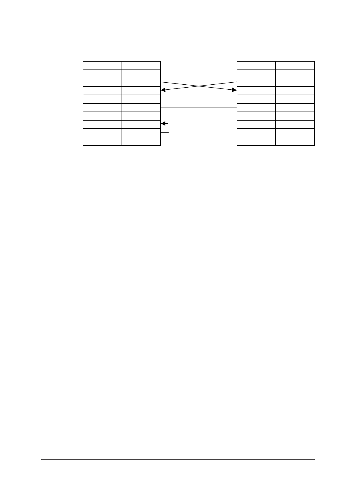
Chapter 3 – Installation and Wiring
CUSTOM FT190SP Printer
Conversion Cable Wiring Diagram
(Dsub 9-Pin)
Pin No. Signal Name Pin No. Signal Name
1DTR
2TXD 2TXD
3RXD 3RXD
4DSR 4RTS
5GND 7GND
6RTS 20DTR
7CTS
8RTS
9
Printer Type Settings Area – Type and Keyboard SIO Baud Rate
PrinterData Transfer Cable
Type: PR201
EPSON (High Quality / High Speed)
HP Laser Jet II
Keyboard SIO Baud Rate: 9600bps
Printer Settings
SET UP DEFAULT:
40 COLUMNS (font 9x24)
PRINT = REVERSE
MODE = LITTLE
FONT 2
CR-LT IGNORE CR
SPEED/CURRENT = LOW
BUFFER 1K BYTE
SERIAL POR T SELECTED
BAUD RATE = 9600
PROTOCOL = 8, N, 1
FLOW CONTROL = XON-XOFF
PRINT KEY TRANSMIT $0D
GLC2300 Series User Manual
3–17

Chapter 3 – Installation and Wiring
Available Printout Features
The following table lists printout features available with the I-ASCII font. Japanese, Korean, Taiwanese, and Chinese fonts are not available.
Printout Features NEC PR201 EPSON ESC/P HP LaserJet
Screen Hard Copy X X X
Print Alarm Message O O O
Real-time print of Q tag alarm O O O
Batch print of Q tag alarm O O O
Print Log Data (Single Block) O O O
3.4 Ethernet Cable Connector
The GLC Ethernet interface is IEEE802.3 compliant, and transmits data at 10
Mbps. Your Ethernet connector can be found on the GLC, as follows:
Ethernet Interface
Pro-face strongly recommends that a trained engineer install
your Ethernet network.
3.5 CF Card Insertion and Removal
CAUTIONS
When using the GLC unit’s CF Card interface, follow these
precautions:
• Prior to inserting or removing a CF Card, turn the GLC unit’s
CF Card ACCESS switch OFF, and confirm that the ACCESS
lamp is not lit, to prevent damage to or loss of CF Card
internal data.
3–18 GLC2300 Series User Manual
Chapter 3 – Installation and Wiring
CAUTIONS
• When the CF Card is being accessed, NEVER:
• turn OFF or reset the GLC unit
• insert or remove the CF Card
Prior to performing these operations, create and use a spe-
cial GLC application screen that will prevent access to the
CF Card.
Refer to the GP-PRO/PB III for Windows Tag Reference
Manual (included in the GP-PRO/PB III C-Package).
• Prior to inserting a CF Card, familiarize yourself with the
CF Card’s front-face and rear-face orientation, as well as
with the CF Card connector’s position. To prevent damage
to the CF Card’s internal data and the GLC unit, the CF
Card must be correctly positioned when it is inserted into
the CF Card slot.
• Use only CF Cards manufactured by Digital Electronics Cor-
poration. GLC unit performance cannot be guaranteed when
another manufacturer’s CF Card is used.
• Lost GLC data cannot be recovered. Since accidental data
loss can occur at any time, be sure to back up all GLC screen
and CF Card data regularly.
• Be sure to follow the instructions below to prevent the mal-
function of a CF Card or the destruction of a CF Card’s
internal data:
• DO NOT bend the CF Card.
• DO NOT drop or strike the CF Card against another
object.
• Keep the CF Card dry.
• DO NOT touch the CF Card connectors.
• DO NOT disassemble or modify the CF Card.
GLC2300 Series User Manual
3–19
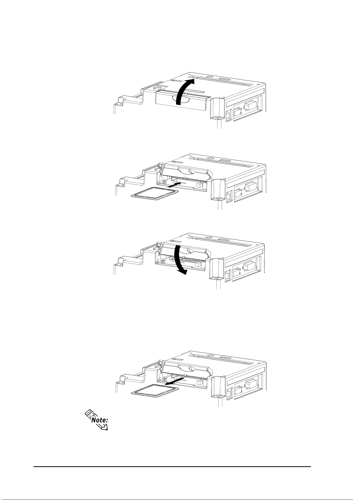
Chapter 3 – Installation and Wiring
Inserting the CF Card
Use the following steps to insert the CF Card in the GLC.
1. To open the CF Card cover, slide it in the direction shown, and then upwards.
2. Insert the CF Card until the ejector button is pushed forward.
3. Close the cover .
4. Confirm that the CF Card Access LED turns ON.
Removing the CF Card
Prior to removing the CF Card, confirm that the CF Card Access LED is turned
OFF. To remove the CF Card, reverse the previous “Inserting the CF Card” steps.
The CF Card cannot begin to access data if the CF Card’s
cover is open. However, if the CF Card is in the process of
accessing data, the CF Card’s cover can then be opened.
3–20 GLC2300 Series User Manual

Chapter 3 – Installation and Wiring
3.5.1 CF Card Handling
The CF Card has a data overwrite limit of approximately 100,000 times. Therefore, be sure to back up all CF Card data regularly to another storage media. (100,000
times assumes the overwriting of 500KB of data in DOS format)
T wo methods are available for backing up data. After using either method (1) or method
(2), use your PC to save your data to the CF Card.
(1) If your PC is equipped with a PC Card Slot
T o view CF Card data on a personal computer , first, insert the CF Card into a CF Card
Adapter .
(2) If your PC is NOT equipped with a PC Card slot
Use a commercially available PC Card Reader, or a CF Card Reader .
GLC2300 Series User Manual
3–21

Chapter 3 – Installation and Wiring
3.6 Flex Network Communication Cable
Use the following procedures to prepare and connect the Flex Network Communication Cable to the Screw Lock Terminal Block.
3.6.1 Cable Preparation
Remove the wire’s external covering and insert the center strand into the connector opening.
Unit: mm [in.]
6 to 8 [0.24 to 0.31]
Blue (TR+)
White(TR-)
25 to 35
[0.98 to 1.38]
• Be sure to tape or put a plastic tube over the shield line.
• Do NOT solder the wire. Doing so could result in insufficient wire to
connector contact.
Shield (SLD)* Do NOT solder end
3.6.2 Flex Network Communication Cable Wiring
Use the following steps to connect the Flex Network Communication Cable to the
Screw Lock Terminal Block.
1. Loosen the set screws on both sides of
the screw lock terminal block, and
remove the screw lock terminal block.
3–22 GLC2300 Series User Manual
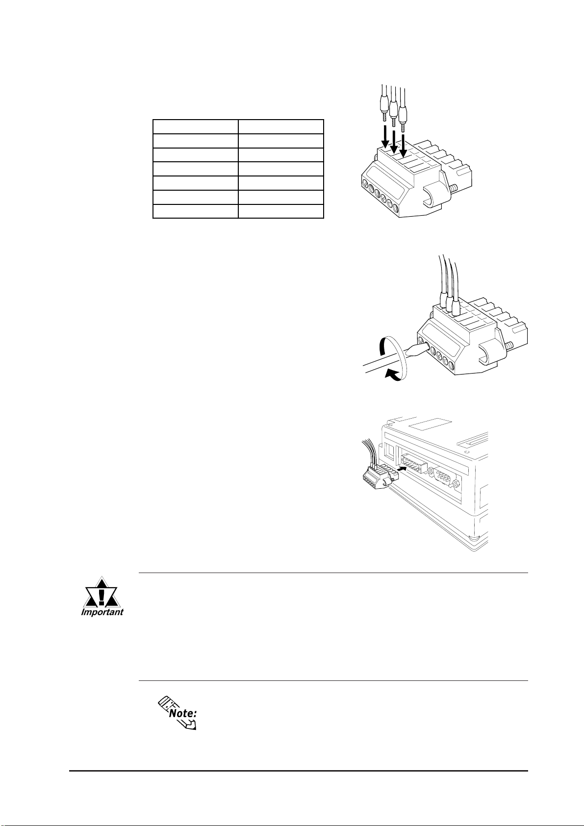
Chapter 3 – Installation and Wiring
2. Loosen the set screws for each desired
pin and insert the cables.
Flex Network
Pin Numbers and Signal Names
Pin number Signal Name
1TR+
2TR3SLD
4TR+
5TR6SLD
3. Make sure that each line (cable) is
inserted completely .
4. Tighten the two (2) set screws.
5. Reattach the screw lock terminal
block to the GLC.
• Be sure that the Flex Network Communication Cable is held securely
in place with a cable clamp. This clamp should be located near the
rear of the GLC. Do NOT use excessive force to tighten the wires’ set
screws.
• If wire ends are not carefully twisted, strands from adjacent wires or
their contact with an electrode may cause a short circuit.
GLC2300 Series User Manual
• Use a small screwdriver (thickness 0.4 mm [0.02 in.], tip
width 2.5 mm [0.10 in.]) to tighten the set screws.
• The recommended torque for tightening the set screws is
0.2 to 0.4 N•m.
3–23

Memo
3–24
GLC2300 Series User Manual

Chapter
4 Data Transfer
This chapter explains how to transfer data created with the screen creation software
using one of the following three (3) methods.
• Transfer data between the GLC and your PC via the data transfer cable.
• Transfer data to the GLC via an Ethernet network.
• Transfer data between the GLC and your PC with the CF Card, using the CF
Memory Loader T ool.
4.1 Serial Data Transfer
The following diagram illustrates the connection between your PC and the GLC with the
data transfer cable.
1. Serial Data Transfer
2. Ethernet Data Transfer
3. CF Memory Loader Tool
GLCPC Data Transfer Cable
T o PC’s
serial port
• Pro-face’s data transfer cable (GPW-CB02) is sold separately . However , the dat a transfer cable package does NOT
include the PC’s interface conversion adapter.
• When using the PC with the Dsub 25-pin socket (female)
interface, a connector conversion adapter is required. Use
the straight-line type of conversion adapter.
Recommended adapters:
Arvel AA833
SANWA SUPPL Y INC. D09-9F25F
• When using a PC equipped with a half-pitch, 14-pin socket
interface, a conversion adapter is required.
Recommended adapter:
LOAS Co. Ltd. ZR01-024
To GLC unit’s
tool connector
Transfer screen data from your PC via the GLC screen creation software.
For details about the GLC screen cr eation software, r efer to GP-PRO/PB III
for Windows Operation Manual (included in the GP-PRO/PB III C-Pack-
age).
4-1GLC2300 Series User Manual

Chapter 4 – Transfer Screen Data
Transfer the logic program data from your PC via the Logic Program Development
Software.
For details about the Logic Program Development Software, refer to
the Pro-Control Editor Operation Manual (included in the
GP-PRO/PB III C-Package).
Transferring Data to a New GLC
Connect the GLC to your PC via the data transfer cable, and then turn the GLC ON.
The Initial Start Mode screen will appear on the GLC and you can transfer logic program data from your PC to the GLC. The screen will change to the Transfer screen
automatically .
Completing Data Transfer Using GLC Setup
When transferring screen data from the GLC screen creation software, the screen
automatically switches to SCREEN DATA TRANSFER. If the screen does not switch to
SCREEN DATA TRANSFER, select SCREEN DATA TRANSFER mode.
During data transfer, the SETUP TRANSFER and NOW TRANSFERRING – PLEASE
messages appear. When these messages disappear , the screen data transfer is
WAIT
completed.
Y ou can cancel data transfer at any time using your GLC screen creation software.
When the screen data transfer is completed, if you do not need to set up the GLC, the
screen designated in INITIAL SETTINGS | SCREEN SETUP | INITIAL SCREEN
FILE NO.
appears, and the GLC screen changes to operation (RUN) mode.
*1
4-2
1. To “Set up the GLC” means to download both the system program and the
user-specified protocol program from the GLC screen creation software to the
GLC unit.
GLC2300 Series User Manual
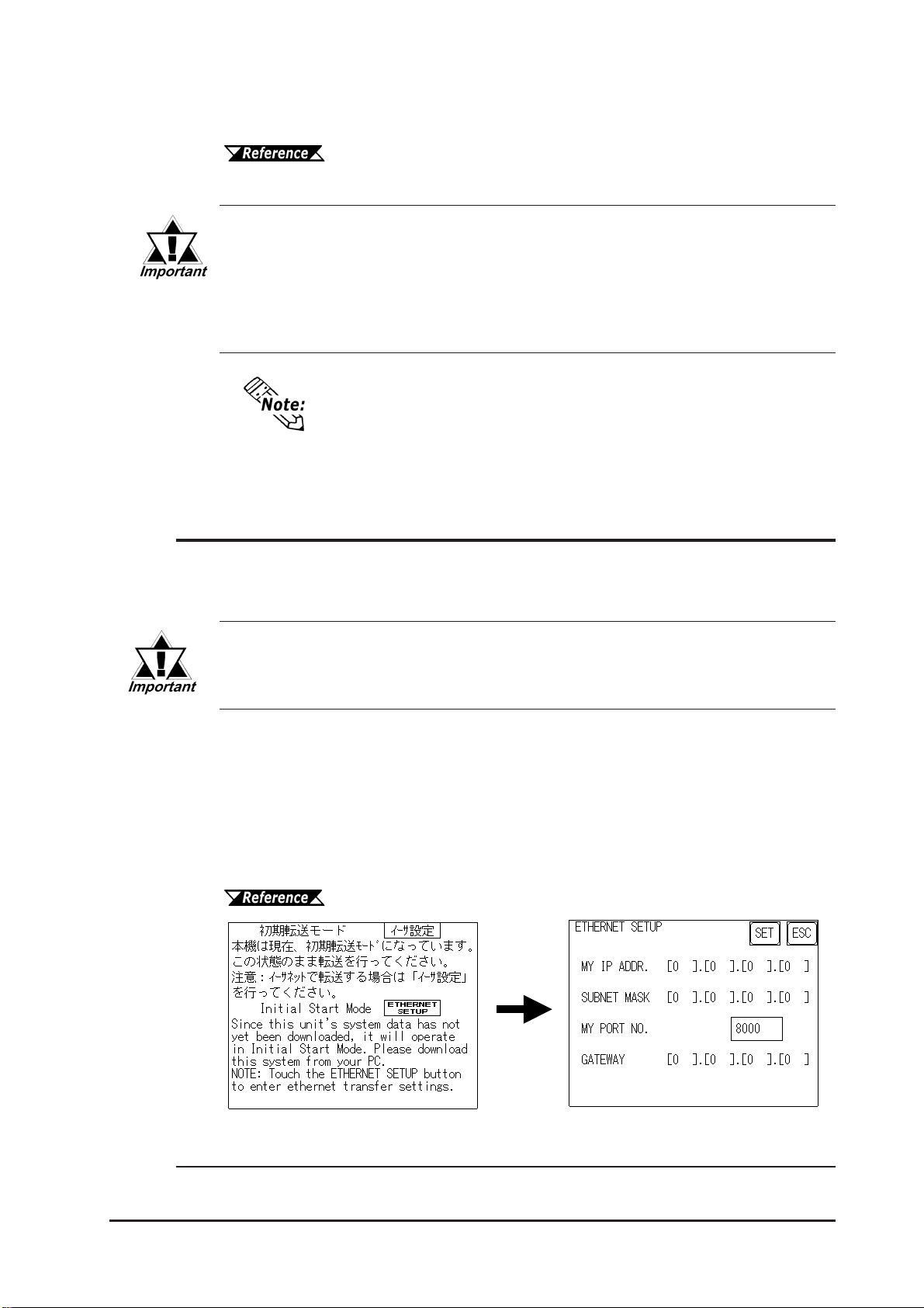
Chapter 4 – Transfer Screen Data
Logic Program Data Transfer is only possible with a GLC that has previously had its
System Data sent to it.
Refer to the Pro-Control Editor Operation Manual (included in the
GP-PRO/PB III C-Package).
Interrupting the screen data transfer can lead to a GLC startup error.
During screen data transfer, do NOT:
• disconnect the GLC unit’s power supply
• turn off the PC
• disconnect the GLC unit’s transfer cable
If the GLC screen creation software’s “GP SYSTEM SETTINGS”
“INITIAL SETTINGS” data will be overwritten.
1
data is transferred to the GLC, the OFFLINE mode
4.2 Ethernet Data Transfer
The GLC2300 Series unit is equipped with the Ethernet I/F which allows you to set up
the GLC via an Ethernet network, as well as transfer GLC screen data.
When using the Ethernet communication protocol, you must specify a
port number 8010 or higher. Otherwise, system setup or screen data
transfer via Ethernet is disabled.
After you connect an Ethernet cable to the GLC’s Ethernet I/F, the GLC will appear on
the Ethernet network.
Transferring Data to a Completely New GLC
Setting Up the IP Address Manually
T ouch the Ethernet Settings button on the Initial Start Mode screen.
1. Even if the GLC OFFLINE display reads “GP,” in this manual the meaning is the same
as “GLC.”
GLC2300 Series User Manual
See 6.5.4 – “ETHERNET SETUP.”
4-3
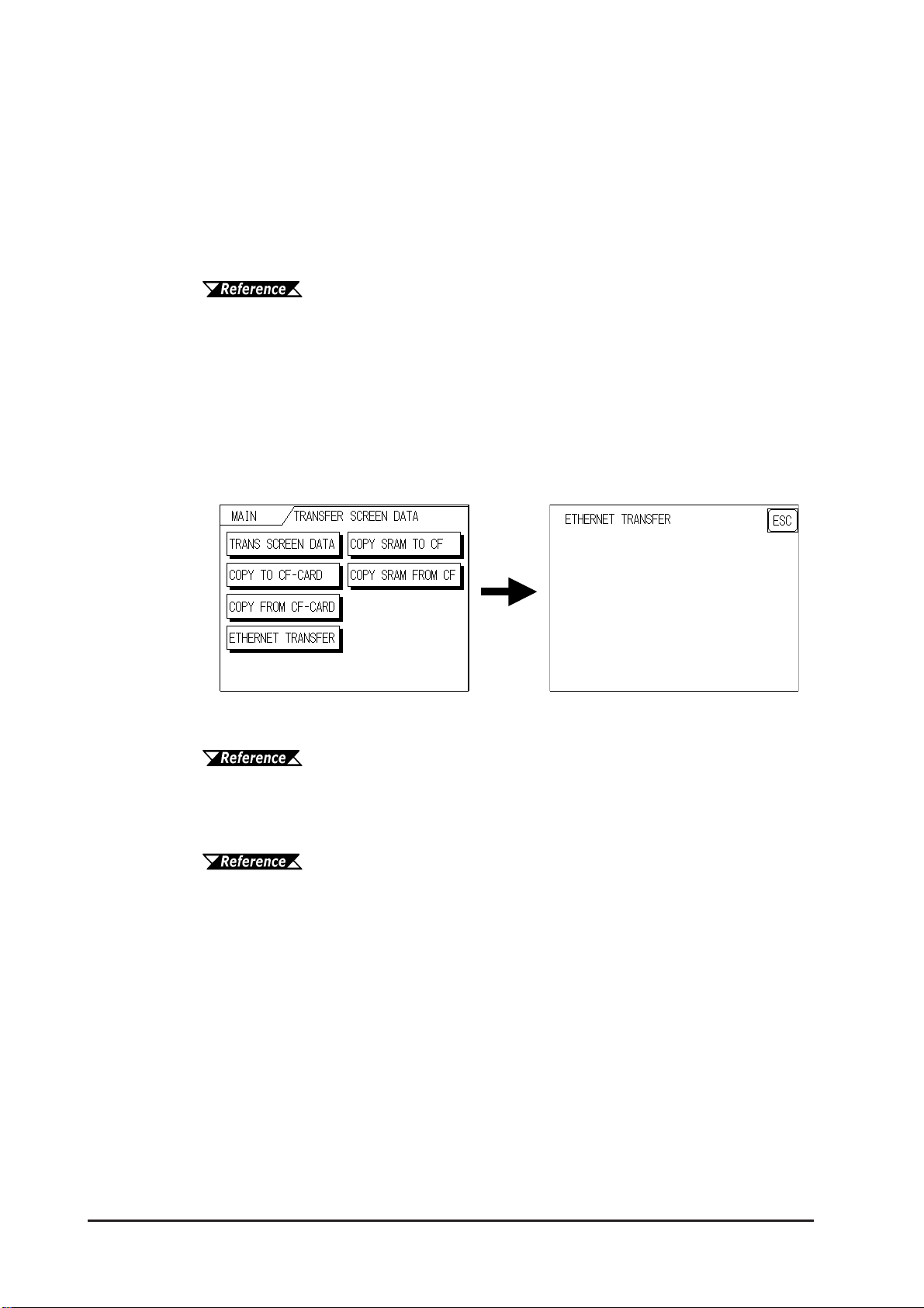
Chapter 4 – Transfer Screen Data
Setting Up the IP Address Automatically
It is not necessary to select Ethernet Settings on the Initial Start Mode screen. When the
options for Ethernet Settings are not specified, they are set automatically .
If you choose to set the GLC unit’s IP address automatically , specify the IP address of
your PC in the range of “10.255.255.1” to “10.255.255.254” and the subnet mask as
“255.0.0.0.”
Transfer data to the GLC using the screen creation software package.
Refer to the GP-PRO/PB III for Windows Operation Manual (in-
cluded in the GP-PRO/PB III C-Package).
When Data Transfer Using the GLC Setup*1 is Completed
When you transfer screen creation software data from your PC to the GLC while the
GLC is in RUN mode, the screen will change automatically to “Ethernet Mode.” If it
does not, you will need to manually change the GLC screen to Ethernet Mode, via the
following screen.
Y ou can now transfer data from your PC’ s screen creation software.
Refer to the GP-PRO/PB III for Windows Operation Manual (included with the GP-PRO/PB III C-Package).
Y ou can also transfer your logic program data from your PC to the GLC via the Logic
Program Development Software.
For details about the Logic Program Development Software, refer to
the GP-PRO/PB III for Windows Operation Manual (included in
the GP-PRO/PB III C-Package).
4-4
GLC2300 Series User Manual

Chapter 4 – Transfer Screen Data
4.2.1 Checking the IP Address
The following procedure explains how to check the IP Address assigned to the GLC as
well as checking precautions.
1. Call up the GLC unit’s menu bar .
For instructions on how
to call up the menu bar,
see 6.4.3 – “SET UP
TOUCH PANEL.”
2. Click on the left-side 1/3 cell of the
menu bar to call up the 2/3 menu.
3. Next, click on the 2/3 cell to call up the
3/3 menu.
4. The IP Address assigned to the GLC
will appear in the menu bar.
After changing “Ethernet
Setup” settings, the GLC
must then be reset or the
power cord must be reconnected. The IP Address will
not appear in this screen
unless the GLC is reset or
the power cord reconnected.
GLC2300 Series User Manual
4-5

Chapter 4 – Transfer Screen Data
4.3 CF Memory Loader Tool
The GLC unit allows you to transfer screen data between your PC and the GLC and to
upload internal GLC data to its CF Card using the CF Memory Loader T ool.
• You need to transfer the CF Memory Loader Tool to the
CF Card prior to using the CF Memory Loader Tool.
Refer to the GP-PRO/PB III for Windows Operation Manual (included in the GP-PRO/PB III C-
Package).
• The combination of the CF Memory Loader Tool and
Backup Data often requires at least 8MB of CF Card
memory. As a result, Digital recommends you use its
CF Card “GP077-CF20 (16MB)” or “GP077-CF30
(32MB).”
Starting the CF Memory Loader Tool
There are two methods for starting this program via the CF Card.
1. Menu Bar: Using the GLC Unit’s [CF BOOT] Menu
Insert the CF Card with the CF Memory Loader T ool saved into the GLC and touch
the OFFLINE menu screen’ s CF BOOT selection. The GLC will be reset, and after
it restarts, the CF card’ s CF Memory Loader T ool will start.
For information about displaying the menu bar, see 6.4.3 – “SET
UP TOUCH PANEL
2. GLC Dip Switches: Forced Start via GLC Dip Switches
.”
4-6
Y ou can also use the Dip Switches on the rear of the GLC, next to the CF Card Slot.
If you turn ON (raise) Dip Switch No. 1 and then connect the GLC unit’s power
cord, the CF Memory Loader T ool will automatically start.
GLC2300 Series User Manual

Chapter 4 – Transfer Screen Data
OFF
ON
CF Card Slot
Dip Switches
When you finish using the CF Memory Loader Tool, turn this
dip switch OFF.
4.3.1 Data Upload and Download
When the Memory Loader T ool program starts, the following screen will appear.
UPLOAD (from GLC Unit to CF Card)
This feature is for saving all GLC internal data (i.e. system program, communication
protocol, expansion program, screen data and Backup SRAM data) in the CF Card as
backup data.
T o start data upload, enter the password you designated in the screen creation
software’s “T ransfer” screen, and then touch the START key . If you have not designated
a password however, touch the START key.
When UPLOAD is performed, the CF Card’s current Backup Data will be
completely overwritten.
GLC2300 Series User Manual
4-7

Chapter 4 – Transfer Screen Data
DOWNLOAD (from CF Card to GLC)
This feature is used for writing CF Card backup data to the GLC unit’s Internal SRAM
Memory .
T o start data download, enter the password you designated in the screen creation
software’s “T ransfer” screen, and touch the START key . If you have not designated a
password, touch the START key .
When DOWNLOAD is performed, the GLC unit’s Internal Memory data
(such as system program, communication protocol, expansion program,
screen data and Backup SRAM data) will be completely overwritten.
4-8
GLC2300 Series User Manual

Chapter
5 OFFLINE Mode
OFFLINE Mode provides access to the GLC unit’ s Initialize menu, Self-Diagnosis
menu, and other GLC features. You will need to change the GLC to
mode before you can use any of these features.
OFFLINE mode is unavailable in a new GLC until the necessary System
data has been transferred from the screen creation software on your
PC. T o transfer system data, the GLC unit’ s power cord must be plugged
in. When you transfer screen data from your PC to the GLC, the GLC
unit’s System data is also automatically sent.
1. Entering OFFLINE Mode
2. OFFLINE Mode Main Menu
3. INITIALIZATION
4. SELF-DIAGNOSIS
OFFLINE
For information about transferring data to the GLC, see Chapter 4 –
“Data Transfer,” or refer to the GP-PRO/PB III for Windows Operation Manual (included in the GP-PRO/PB III C-Package).
5.1 Entering OFFLINE Mode
To INITIALIZE your GLC or to perform a SELF-DIAGNOSIS, you must first
switch the GLC to OFFLINE mode. This can be done using either of two methods;
immediately after plugging in the GLC unit’s power cord, or by using the Forced
Reset feature.
Be aware that, when changing a Logic Program from RUN to OFFLINE
mode, and regardless of the current output hold setting, the GLC unit’s
and the I/O signals’ processes are as follows:
GLC Con diti o n RUN O F F L INE RUN
ON
I/O S i gnal
OFF
Output from
Logic P rogram
OFF
When using the RESET command, the timing of the GLC unit’ s I/O signal OFF
timing is not fixed and can vary.
Output from
Logic P rogram
5–1GLC2300 Series User Manual

Chapter 5 – OFFLINE Mode
5.1.1 After Plugging in the Power Cord
To enter OFFLINE mode, touch the top-left corner of the screen within 10 seconds
after connecting the GLC unit’s power cord.
The logic program runs for 10 seconds before entering OFFLINE mode.
Be sure that the I/O signals have been reset before changing to OFFLINE
mode.
5.1.2 From the Menu Bar
From the GLC unit’s menu bar, touch OFFLINE, and the Main Menu appears.
To call up the Menu Bar , see 6.4.3 – “SET UP T OUCH PANEL;
FORCED RESET.”
If your GLC unit includes the Device Monitor feature, the MONITOR button will be included on the menu bar.
Refer to the GP-PRO/PB III for Windows Device/PLC Connection
Manual (included in the GP-PRO/PB III C-Package).
5–2 GLC2300 Series User Manual

Chapter 5 – OFFLINE Mode
When the system enters OFFLINE mode, the I/O setting is reset. If there is no
problem resetting the I/O setting, touch YES. If a password is set in the INITIAL-
IZE | SET UP SYSTEM
mode. Enter the password, then touch SET to enter OFFLINE mode.
For more information about passwords, see 6.3.1 – “SYSTEM
SETUP.
5.3 — INITIALIZATION.”
area, the following screen appears before entering OFFLINE
” For information about entering password numbers, see
5.2 OFFLINE Mode Main Menu
The Main Menu contains the following menu items: INITIALIZE, SCREEN DATA
TRANSFER,
The settings for each menu item, below, must match the corresponding PLC, for
the GLC to communicate properly.
Entering OFFLINE mode calls up the following screen.
Select the desired menu item by touching the corresponding option.
Each Main Menu item is used as follows:
SELF-DIAGNOSIS, and RUN.
INITIALIZE
Setup items control the GLC unit.
GLC2300 Series User Manual
For more information about INITIALIZE, see Chapter 6 –
“Initializing the GLC.”
5–3

Chapter 5 – OFFLINE Mode
SCREEN DATA TRANSFER
Transfers screen data between the screen creation software and the GLC.
For more information about TRANSFER SCREEN DATA, see Chap-
ter 4 – “Data Transfer” or refer to the GP-PRO/PB III for W indows
Operation Manual (included in the GP-PRO/PB III C-Package).
SELF-DIAGNOSIS
Checks to see if there are any problems with the GLC System or Interface (I/F).
RUN
Starts GLC operation.
For more information about the SELF-DIAGNOSIS and RUN features,
see Chapter 7 – “Run Mode and Errors.”
5.3 INITIALIZATION
Selecting a Menu
Touch the menu item or input field to select.
Entering Numbers
After selecting an input field, touch the numeric touch keys located at the bottom
of the screen to enter the value of the selected item. After entering each input
field’s numeric value, touch the [SET] key to register the value.
5–4 GLC2300 Series User Manual

Chapter 5 – OFFLINE Mode
Selecting Setup Conditions
After selecting a menu item, touch the setting option to highlight the item, then
touch the setting area to set the condition for that item.
In this example, touching the ON/OFF area toggles the TOUCH BUZZER SOUND
setting, which is set to OFF, and then switched to ON.
After Entering All Setting Data
Touch the top-right [SET] key to write the setup data to the Internal FEPROM.
Touch [CANCEL] to cancel the setup, exit the screen without saving the changes,
and return to the previous menu.
• Press the [SET] key to write the Setup conditions onto the
Internal FEPROM.
• Since the Setup conditions are written onto the Internal
FEPROM by pressing the [SET] key , it may take some time
returning to the previous menu. Until returning to the previous menu, do not touch the screen.
• Press the [CANCEL] key to not write the Setup conditions
onto the Internal FEPROM and return to the previous menu.
Returning to a Previous Screen
Touch the tab to call up the desired menu.
For example, to return to the MAIN MENU from the SYS. ENVIRONMENT screen,
touch the MAIN MENU tab.
GLC2300 Series User Manual
5–5

Chapter 5 – OFFLINE Mode
5.4 SELF-DIAGNOSIS
Selecting a Sub-Menu
Touch the desired menu item and the corresponding sub-menu appears.
Using the [SET] and [ESC] Keys
After selecting the Self Diagnosis item, the [SET], and [ESC] keys may appear at
different times at the top of the screen.
[SET] Key
Touch the [SET] key to start the Self-Diagnosis test.
[ESC] Key
Touch the [ESC] key to cancel the Self-Diagnosis test and return to the
SELF-DIAGNOSIS menu.
Returning to the SELF-DIAGNOSIS Menu
After performing the Self-Diagnosis check, OK is displayed. Touch once anywhere on the display screen to return to the SELF-DIAGNOSIS MENU.
5–6 GLC2300 Series User Manual

Chapter 5 – OFFLINE Mode
If an Error Message displays, press the bottom-left corners of the panel [1], and
then touch the bottom-right corner of the panel [2] to return to the SELF-DIAGNO-
SIS MENU
Returning to the Main Menu
Touch the [MAIN] key to return to the Main Menu screen.
.
GLC2300 Series User Manual
5–7

Memo
5–8 GLC2300 Series User Manual

1. Initialization Screen
2. Initialization Items
3.
SYSTEM ENVIRONMENT SETUP
Chapter
4. SET UP I/O
6 Initializing the GLC
6.1 Initialization Screen
To change your GLC unit’s general operation settings, use the GLC unit’s
OFFLINE mode to access the items in the
5. PLC SETUP
6. INITIALIZE INTERNAL MEMORY
7. SET UP TIME
8. SET UP SCREEN
9. Font Setting
MAIN MENU | INITIALIZE option.
This chapter explains each of the
there are two (2) types of
INITIALIZE settings, those for the 1:1 connection and
those for the n:1 (multi-link) connection
OFFLINE mode’s INITIALIZE items. However,
*1
.
The n:1 mark appears on original menu items related to n:1 multi-link connection
items. If there is no mark, the menu item is common to both 1:1 and n:1 connections.
1:1 A single (1) GLC is connected with a single (1) PLC.
n:1 Multiple GLCs are connected with a single PLC. The GLCs successively pass
a PLC Access T oken (exclusive PLC interaction key) among themselves to
designate which unit can communicate with the PLC.
If you transfer the GLC unit’s system file data to the GLC
•
via your screen creation software
ing that data. If the GLC System file has been correctly set
up and transferred, then setting up the following INITIALIZE items is unnecessary.
*2
, the GLC operates us-
For more information about GLC System files, refer to the GP-PRO/PB III for Windows Operation
Manual (included with the GP-PRO/PB III C-Package).
• In instances where “GP” is displayed on the GLC unit’s
OFFLINE screen, the term “GLC” can be substituted.
1. PLCs that support the n:1 (multi-link) connection are limited.
Refer to the Pro-Control Editor Operation Manual (included with
the GP-PRO/PB III C-Package).
2. Refer to the GLC screen creation software’s “SYSTEM SETTINGS” area.
GLC2300 Series User Manual 6–1
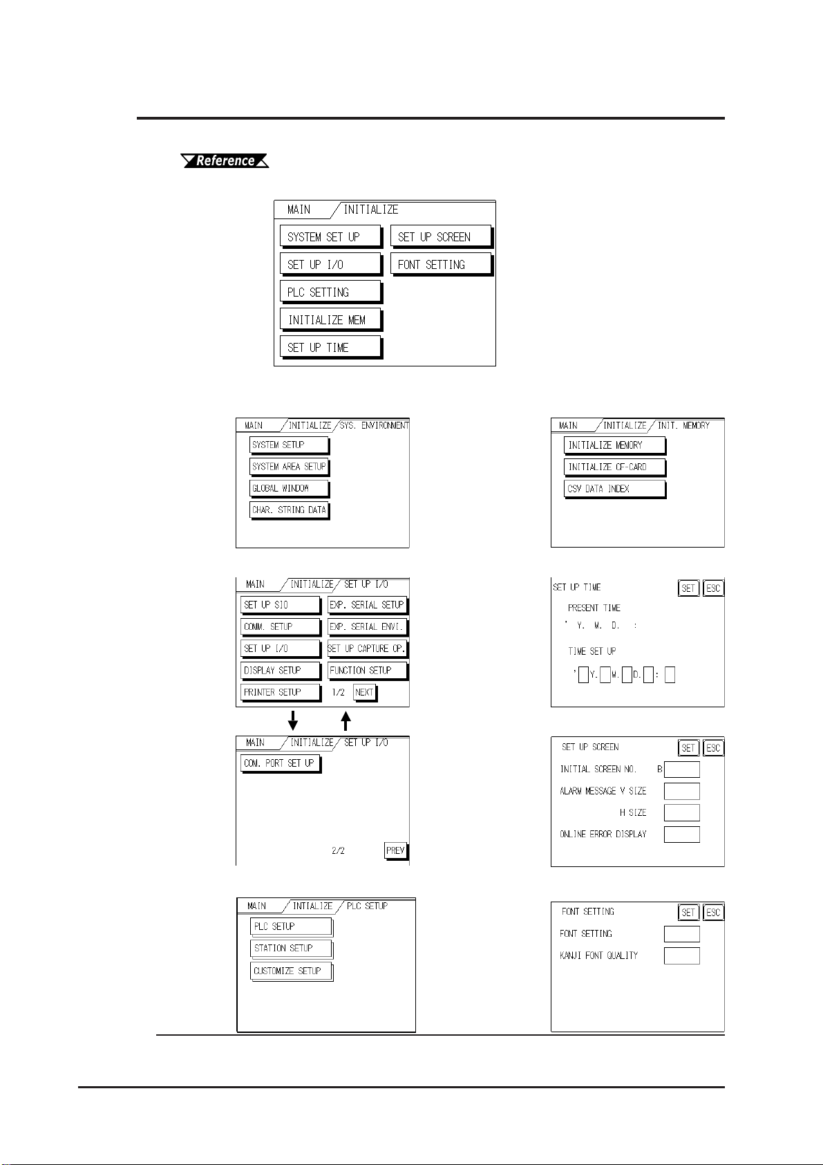
Chapter 6 – Initializing the GLC
6.2 Initialization Items
This chapter explains the contents of the Initialize setup items listed below.
For information about screen operations and numeric input, see Chapter 5 – “OFFLINE Mode.”
The INITIALIZE menu includes the following items:
SYSTEM ENVIRONMENT
SETUP
SYSTEM SETUP
SYSTEM AREA SETUP
GLOBAL WINDOW SETUP
CHARACTER STRING DATA
SETUP
SET UP I/O
SET UP SIO
COMM. SETUP
SET UP I/O
DISPLAY SETUP
PRINTER SETUP
EXP. SERIAL SETUP
EXP. SERIAL ENVI.
SET UP CAPTURE OP.
FUNCTION SETUP
COM. PORT SET UP
INITIALIZE MEMORY
INITIALIZE MEMORY
INITIALIZE CF CARD
CSV DATA INDEX
SET UP TIME
SET UP SCREEN
PLC SETUP
PLC SETUP
STATION SETUP
CUSTOMIZE SETUP
*1
FONT SETTING
1. Depending on the Device/PLC type selected, the screens that appear in your GLC
unit’s screen creation software will vary.
6–2
GLC2300 Series User Manual
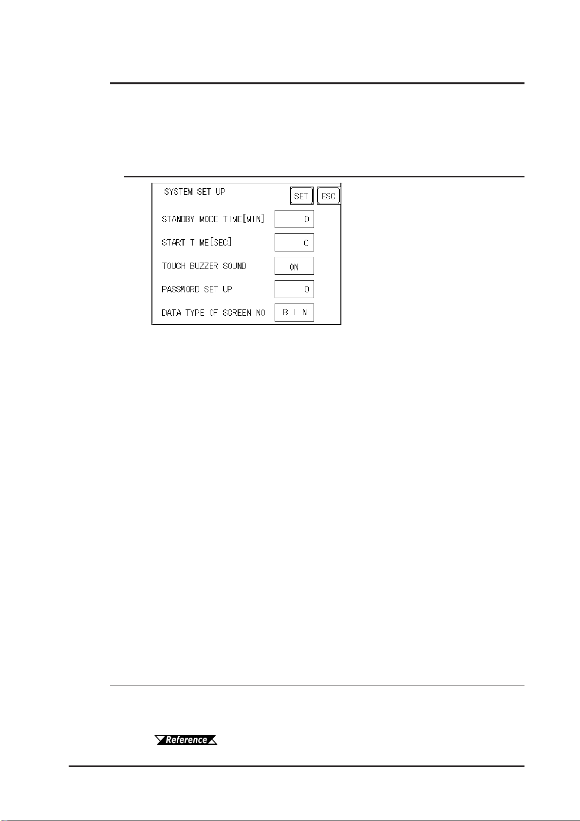
Chapter 6 – Initializing the GLC
6.3 System Environment Setup
Adjustments to the GLC operation environment are made within the setup screens
contained in the SYSTEM ENVIRONMENT SETUP menu. Screens include the
SYSTEM SETUP, SYSTEM DATA AREA, GLOBAL WINDOW SETUP, and CHARACTER STRING DATA SETUP
6.3.1 SYSTEM SETUP
screens.
STANDBY MODE TIME (0–255)
To protect the GLC unit’ s display screen, a screen saver function automatically turns
the unit’s backlight(s) OFF when no operations have occurred within a specified
period of time. No screen saver will be used when “0” is entered in this field.
When the SYSTEM DAT A AREA’s SCREEN DISPLAY OFF*1 data is set to 0000h,
the GLC unit’s current display data will clear if the following operations are not
performed within the user’s specified period of time:
• Change Screen • Touch Screen
• Alarm Message (scrolling display)
• Error Message Display (Except for 2Way Error)
• Menu Bar (for forced reset) display • Japanese (FEP) System window
START TIME (0–255)
Use this setting item to specify the GLC unit’s startup time — or to adjust the
powering-up sequence — so that the GLC starts up after the PLCs start.
TOUCH BUZZER SOUND
This setting item indicates, with a buzzing sound, that the GLC has been touched.
PASSWORD SETUP
The password setting item is used when the GLC switches to the Initialize Memory or
Initialize (OFFLINE mode) screens. The password — a number between 0 and 9999
— is a security feature within the OFFLINE mode, to protect the GLC settings. If you
do not wish to use this feature, enter the default value, “0.”
1. When using the Direct Access format, the object address becomes LS0009. When
using the Memory Link format, the object address becomes +12. (Only when all items
are set within the System Data Area.)
GP-PRO/PB III for Windows Device/PLC Connection Manual
(included with the GP-PRO/PB III C-Package)
GLC2300 Series User Manual 6–3
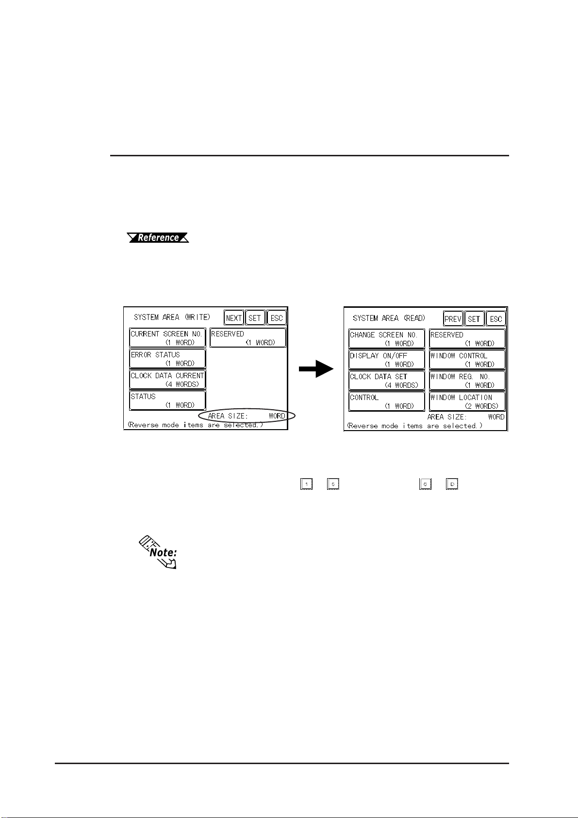
Chapter 6 – Initializing the GLC
DATA TYPE OF SCREEN NO.
This setting specifies whether BIN or BCD format numbers are used when making
screen changes. Screen numbers 1 to 8999 are available for binary format. Screen
numbers 1 to 1999 are available for BCD format.
6.3.2 SYSTEM AREA SETUP
The PLC contains and uses the System Data Area to control its GLC-related data.
Different types of devices can be set up in the System Data Area, depending on
the PLC type.
When the GLC uses Memory Link format, this setting is unnecessary.
GP-PRO/PB III for Windows Device/PLC Connection Manual (included with the GP-PRO/PB III C-Package)
Touch the number for the item desired. The item will change to reverse video, to
show it has been selected.
System Area Size
This field displays the total number of words used for the items selected from the
SYSTEM AREA SETUP (Write: from to and Read: from to ).
When you press the Confirm key, the SYSTEM AREA CONTENTS screen is
displayed, to confirm the selected items.
• The System Area settings are enabled only when using
Direct Access format.
• The selected System Area items, as displayed on the
screen, become the System Data Area.
6–4
GLC2300 Series User Manual

Chapter 6 – Initializing the GLC
When the Current Screen Number, Error Status, Clock Data (Current), Change
Screen Number, and Display ON/Off setting items have been selected, a word
address is assigned to each item, in order, as shown.
In the above screen, the device address used for the SET UP OPERATION SUR-
ROUNDINGS
Therefore, when the SYSTEM AREA START DEV | START ADR is “D00200,” and
the CHANGE SCREEN NO. setting has been designated, the address shown is
“+6” and you will then need to enter “D00206” (D00200 + 6) to use this address.
setting’s SYSTEM AREA ST ART DEV | START ADR is “+0.”
For details about setting the SYSTEM AREA ST ART DEV | START ADR,,
see Section
(1:1 / n:1).”
6.5.1 – “SET UP OPERATION SURROUNDINGS
6.3.3 GLOBAL WINDOW SETUP
A GLC2300 Series unit can display one Global Window and two Local Windows
simultaneously. The Global Window is common to all the display screens. The
Local Window displays exclusively on a designated base screen. This section
describes the GLOBAL WINDOW SETUP is described here.
GLC2300 Series User Manual 6–5

Chapter 6 – Initializing the GLC
GLOBAL WINDOW
Two options are available: Use and Do Not Use. If you select Do Not Use, ignore
the items described below. Selecting Use enables the following options.
GLOBAL WINDOW ACCESS
Use this feature to designate whether values used by the GLC (such as the REGIS-
TRATION NO.
Direct, the REGISTRATION NO. and LOCATION selections are fixed to the values
entered here. When set to Indirect, the WINDOW REG. NO.’s word address is used
by the SYSTEM AREA as a variable. This means the REGISTRATION NO. written
to it changes and, as a result, can call up multiple window screens as Global
windows. You can also use this method to adjust the Global window’s position by
writing the desired (X,Y) coordinates to the SYSTEM AREA’s LOCATION word
addresses.
DATA FORMAT
Set up the REGISTRATION NO. and the LOCATION values as either BIN or BCD
values. This field is related only to Indirect values.
and the LOCATION values) are DIRECT or INDIRECT. When set as
REGISTRATION NO.
Enter the Window Screen Number used by the Global Window. This field is
enabled only when GLOBAL WINDOW ACCESS is set to Direct.
WINDOW LOCATION
Enter the value used for the (Global Window) LOCATION. This field is enabled
only when GLOBAL WINDOW ACCESS is set to Direct. Use this setting to designate the top-left coordinate on the screen registered as a Global Window. If you
install the GLC vertically, (in portrait — not landscape — mode), designate the
bottom-left instead of the top-left coordinate.
6.3.4 CHARACTER STRING DATA SETUP
Character String Data ordering varies from manufacturer to manufacturer . Set up
the Character String Data order to match that of the corresponding PLC.
6–6
Set up the CHARACTER STRING DA TA MODE to match that of the corresponding PLC. Device type and T ag settings are not available for setup.
GLC2300 Series User Manual
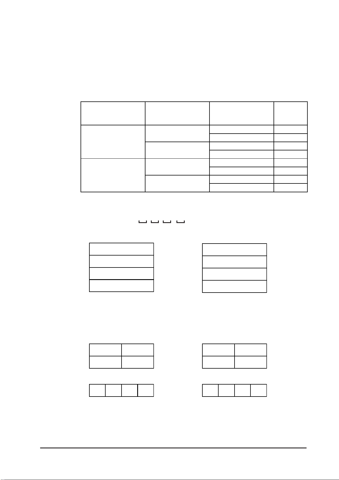
Chapter 6 – Initializing the GLC
CHARACTER STRING DATA MODE
Set up the CHARACTER STRING DATA MODE that corresponds to that of your
PLC, as specified in the following table.
(I) Data Device Storage Order
(II) Byte Storage Order (LH/HL), using single words
(III) Word Storage Order (LH/HL), using double words
CHARACTER STRING DATA MODE (1–8) List
(I) Data Device
Storage Order
Storage from
Start Data
Storage from
End Data
(II) Byte Storage
Order (LH/HL),
using single word
LH order
HL order
LH order
HL order
(III) Word Storage Order
(LH/HL), using
double words
LH order
HL order
LH order
HL order
LH order
HL order
LH order
HL order
Character
String Data
Mode
4
2
5
1
6
7
8
3
I. Data Device Storage Order
Example characters:A B C D E F G H
• Storage from Start Data • Storage from End Data
D100
D101
D102
D103
II. Byte Storage Order (LH/HL), using Single Words
Example characters:A B C D
• 16-bit Device LH Order • 16-bit Device HL Order
D100
D101
D100
D101
D102
D103
D100
D101
• 32-bit Device LH Order • 32-bit Device HL Order
D100 D100
GLC2300 Series User Manual 6–7

Chapter 6 – Initializing the GLC
III. Word Storage Order (LH/HL), using Double Words
Example characters:A B C D E F G H I J
• 16-bit Device LH Order • 16-bit Device HL Order
D100
D100
D101
D102
D103
D104
D101
D102
D103
D104
Example characters:A B C D E F G H I J K L M N O P Q R S T
• 32-bit Device LH Order • 32-bit Device HL Order
D100
D101
D102
D103
D104
D100
D101
D102
D103
D104
Relationship between K-tag Write Character Value and the PLC device.
16-bit Devices
The GLC stores the character string in one internal Device, in groups of two,
starting with the first pair of characters.
When nine characters make up a string, they are arranged as follows:
1 2 3 4 5 6 7 8 9 Null
When the characters do not divide evenly by two, NULL is
added to the last character to make up the final pair and complete the string.
32-bit Devices
The GLC stores the character string in one internal device address, in groups of
four, starting with the first group of characters.
When there are nine characters, they are arranged as follows:
1 2 3 4 5 6 7 8 9 Null
When the characters do not divide evenly by four, NULL is
added to the last character to make up the final group and
complete the string.
6–8
GLC2300 Series User Manual

Chapter 6 – Initializing the GLC
6.4 SET UP I/O
This section describes the communication setup with the Host (PLC) and the
configuration for any peripheral equipment. The SET UP I/O menu includes the
SET UP SIO, COMMUNICATION SETUP, SETUP I/O, DISPLA Y SETUP, PRINTER
SETUP, EXPANSION SERIAL SETUP
SETUP, FUNCTION SETUP
and COMMUNICATION PROT SET UP menus.
6.4.1 SET UP SIO
This screen controls the settings related to communication with the PLCs. Be sure
to match the settings listed below with the SIO setup on the Host (PLC). The
settings will vary, depending on the PLC.
Be sure to match the GLC unit’ s SIO settings, as follows, with those of the host (PLC).
GP-PRO/PB III for Windows Device/PLC Connection Manual (in-
cluded with the GP-PRO/PB III C-Package)
, EXPANSION SERIAL ENVIRONMENT
If you have selected "YES" for the [SERIAL I/F CHANGE] on the [COMMUNICATION
PORT SETUP] screen, or "Yes" for the [Serial I/F Switch] settings in the [Change
Extend SIO Type] command, in the Screen Editor's [Project] menu, do not enter all of
the settings related to device communication using the Extended SIO Script Protocol
here. ([SET UP SIO] screen) These settings are required to set using the [EXPAN-
SION SERIAL COMMUNICATION SETUP] screen.
6.4.6 Expansion Serial Setup
COMMUNICATION RATE
The COMMUNICATION RATE (baud rate) is the data communication speed,
measured in bits per second (bps), between the GLC and the PLC. Match both the
PLC and the GLC units’ COMMUNICATION RATE values. Depending on the rate
selected, you may not be able to use certain PLCs.
GP-PRO/PB III for Windows Device/PLC Connection Manual (in-
cluded with the GP-PRO/PB III C-Package)
DATA LENGTH / STOP BIT
For data communication, use the following settings:
• DATA LENGTH: 7 or 8 bits
• STOP BIT: 1 or 2 bits
PARITY
Use this setting to specify whether an ODD or EVEN number parity check, or none
at all (OFF), will take place during communication.
GLC2300 Series User Manual 6–9

Chapter 6 – Initializing the GLC
CONTROL
The CONTROL setting prevents the overflow of data transmitted and received.
Select either the XON/XOFF or the ER (DTR) control.
COMMUNICATION FORMAT
Select one of the following options for the Communication Format setting:
• RS-232C
• RS-422 (4-line)
• RS-422 (2-line)
• When using an RS-422 cable and the Memory Link format,
be sure to select the 4-line option.
GP-PRO/PB III for Windows Device/PLC Connec-
tion Manual (included with the GP-PRO/PB III C-Package)
• If you have selected "YES" for the [SERIAL I/F CHANGE] on
the [COMMUNICATION PORT SETUP] screen, or "Yes" for
the [Serial I/F Switch] settings in the [Change Extend SIO Type]
command, in the GP Screen Editor's [Project] menu, be sure
to select RS-232C.
6.4.2 COMMUNICATION SETUP
This section explains how to use the Retry command to deal with errors, including
those that occur during GLC and PLC communication.
RECEIVE TIMEOUT (1 to 127)
Use a numeric value to set a period of time in which the GLC receives data from
the PLC. If the cable is not connected, data communication will Timeout after one
second, regardless of this setting’s value.
The default value for the RECEIVE TIMEOUT setting is 10 seconds.
6–10
An error message may appear on your personal computer if:
• Y ou transfer screens from your PC to the GLC after a PLC
communication error has occurred and the error is not yet
cleared.
• Your GLC unit’s RECEIVE TIMEOUT value is set to 30
seconds or more.
GLC2300 Series User Manual

Chapter 6 – Initializing the GLC
RETRY COUNT (0 to 255)
Use this setting item to designate the number of times the GLC tries to send data
to the PLC when a PLC communication error occurs. After the GLC unit’s specified number of attempts has failed to send data to the PLC, an error message will
appear on the GLC.
The default value for the Retry Count setting is “2.”
6.4.3 SET UP TOUCH PANEL
Set up the touch panel’s Touch Operation and Force Reset modes, and adjust the
Display Device settings in this screen. Depending on the GLC type, these settings
may vary .
GLC2300L Setup Screen
GLC2300T Setup Screen
TOUCH OPERATION MODE
Designates One Point, Two Points, or No Slide. When No Slide is selected, the
screen will NOT respond to one’s finger dragging across the touch screen. Only
individually-selected points will register.
GLC2300 Series User Manual 6–11

Chapter 6 – Initializing the GLC
FORCE RESET MODE
Enables or disables the display of the menu bar (force reset page). When set to
“Yes,” the menu bar will display.
To Display the Menu Bar
To enter the SYSTEM RESET mode, press the bottom-right corner of the screen
(position 1, below), and then touch the top-right and bottom-left corners (positions 2 and 3).
To activate Reset, touch the RESET button; to change to OFFLINE Mode, touch
OFFLINE.
Y ou can perform FORCE RESET in either RUN mode or OFFLINE mode.
• The Menu Bar will not display when the GLC is starting up.
• Entering SYSTEM RESET is possible even when the PLC
and GLC are not communicating.
CONTRAST ADJUSTMENT
When this option is set ON, CONTRAST ADJUSTMENTs can be made through
touch input. (GLC2300T is not equipped with CONTRAST ADJUSTMENT
feature.)
Be sure to press the GLC corners in the order shown. If only corner (2)
is pressed OFFLINE mode will start.
6–12
GLC2300 Series User Manual
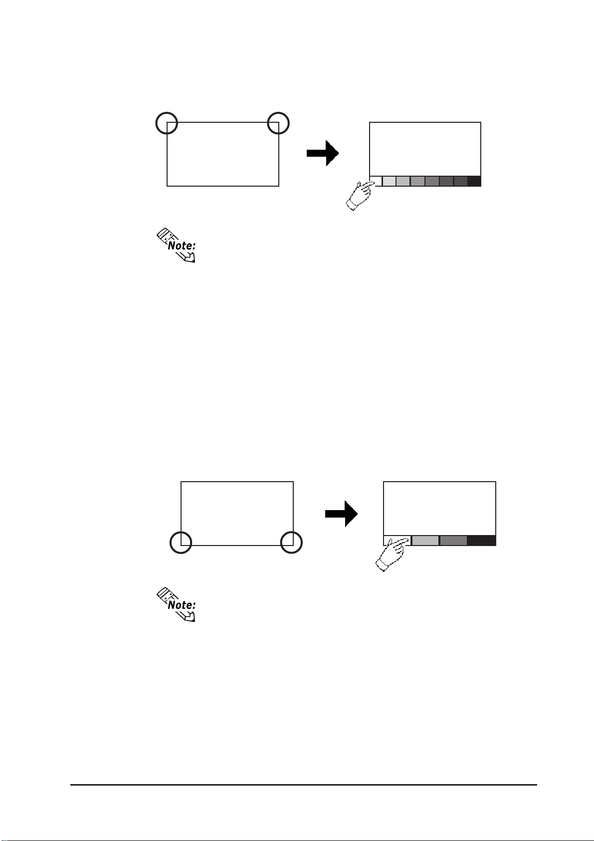
Chapter 6 – Initializing the GLC
While pressing the top-right corner (1) of the screen, press the top-left corner (2)
to enter CONTRAST ADJUSTMENT mode. Press the desired setting, and the
screen’ s contrast will change accordingly.
21
Bright Dark
Normal Display
• To exit the CONTRAST ADJUSTMENT mode, touch anywhere on the screen, except the bottom section.
• CONTRAST ADJUSTMENT mode cannot be entered while
waiting for GLC to start up.
• CONTRAST ADJUSTMENT settings can be made during
RUN mode (PLC<->GLC communication).
• Regardless of a normal and reversed display, the left side
of the contrast adjustment bar, displayed at the bottom area
of the screen, is always “Bright.”
BRIGHTNESS ADJUSTMENT
When set to ON, BRIGHTNESS ADJUSTMENT can be performed via touch
input. Press the bottom-left corner (2) of the screen while holding down the
bottom-right corner (1) to enter BRIGHTNESS ADJUSTMENT mode. Touch the
left side of the bar to brighten the display, and touch the right side of the bar to
dim the display. This unit has four levels of adjustment.
Bright Dark
21
• T o exit the BRIGHTNESS ADJUSTMENT mode, touch anywhere above the Brightness Adjustment bar.
• Y ou cannot enter the BRIGHTNESS ADJUSTMENT mode
while the GLC is starting up.
• BRIGHTNESS ADJUSTMENT settings can be made dur-
ing RUN mode (PLC<->GLC communication).
• One of the characteristics of the display device is that, once
it is plugged into the power source, it takes some time to
reach the maximum practical brightness. At room temperature, the display device takes about 10 minutes to reach
70% of its maximum practical brightness.
GLC2300 Series User Manual
6–13
 Loading...