

Digital Electronics Corporation Pro-Face FP3700-T41 User Manual
FP3700-T41
User Manual
Digital Electronics Corporation

Preface
Preface
Thank you for purchasing Digital’s TFT type color display panel, the 'FP3700T41' (hereafter referred to as the FP unit).
The FP unit is a TFT type color liquid crystal display monitor for Windows
compatible personal computers (XGA mode).
Please read this manual completely to insure the correct use and complete
understanding of the FP unit's functions. The FP's analog interface and DVI-D
interface are designed for using standard VGA mode. Be aware that this unit
may not be able to be connected using a nonstandard VGA mode. For more
details, please refer to this manual's "PC Connectivity Notes" section.
®
<Note>
1) It is forbidden to copy the contents of this manual, in whole or in part, except
for the user's personal use, without the express permission of Digital Electronics Corporation of Japan.
2) The information provided in this manual is subject to change without notice.
3) This manual has been written with care and attention to detail; however, should
you find any errors or omissions, please contact Digital Electronics and inform
them of your findings.
4) Regardless of the above clause, Digital Electronics Corporation shall not be
held responsible for any damages or third-party claims for damages or losses
resulting from the use of this product.
All Company/Manufacturer names used in this manual are the registered trademarks of their respective companies.
©2003, Digital Electronics Corporation
FP3700-T41 User Manual i
Preface
Essential Safety Precautions
This manual describes safety instructions for correct use of the FP unit. Please
keep this manual close at hand and refer to it when necessary.
The following symbols are used throughout this manual to ensure the safe use of
the FP unit. Please be sure to follow all instructions given since they explain
important safety points.
Indicates situations where sever bodily injury,
Warning
Caution
death or major equitment damage will occur.
Indicates situations where bodily injry or machine
damage can occur.
Documentation Conventions
The list below describes the symbols used in this manual.
Explains a situation that requires a moderate amount of caution.
Indicates a word or phrase that has an additional explanation.
*1
1),
2)
A reference point. Describes the word or phrase marked by the asterisk (*) and the corresponding number.
Indicates related information.
Operational steps. Please follow these numbered steps in order to
perform the desired operation.
ii FP3700-T41 User Manual
Preface
WARNINGS
• Because of the ever present danger of electrical shock, be
sure to unplug the power cable from the FP unit before plugging the cable's other end into the wall.
• Do not use power in excess of the unit's specified voltage
range since it may cause a fire or electric shock.
• Because the FP unit contains high voltage parts, an electric
shock can occur when disassembling the unit. Therefore,
be sure to always unplug the unit before disassembling it.
• Do not modify the FP unit in any way, since it may cause a
fire or electric shock.
• Do not use touch panel keys to perform life-threatening or
vitally important safety functions. Use separate mechanical switches for such keys.
• Do not use the FP unit as a warning device for critical alarms
that can cause serious operator injury, machine damage or
production stoppage. Critical alarm indicators and their control/activator units must be designed using stand-alone
hardware and/or mechanical interlocks.
• After the FP’s backlight burns out, unlike the FP’s “Standby
Mode”, the touch panel is still active. If the operator fails to
notice that the backlight is burned out and touches the panel,
a potentially dangerous machine miss-operation can occur .
Therefore, do not use FP touch switches for the control of
any equipment safety mechanisms, such as Emergency Stop
switches, etc. that protect humans and equipment from injury and damage.
If your FP's backlight suddenly turns OFF, use the following
steps to determine if the backlight is actually burned out.
1) If your currentFP application is not set to turn the backlight OFF, and the screen has gone blank, your backlight is
burned out.
2) If your current FP application is set to turn the backlight
OFF, if touching the screen does not cause the display to
reappear, your backlight is burned out.
FP3700-T41 User Manual iii
Preface
WARNINGS
• If substantial amounts of metallic dust, water or liquids enter the FP unit, turn off the power supply immediately, unplug the power cord, and contact your local FP distributor.
• When installing the FP unit, be sure to follow the instructions given in “Chapter 3 Installation and Wiring," to insure
it is done correctly.
• Do not use the FP in an environment with flammable gas,
since it may cause an explosion.
• The FP is not appropriate for use with aircraft control devices, aerospace equipment, central trunk data transmission (communication) devices, nuclear power control devices, or medical life support equipment, due to these devices’ inherent requirements of extremely high levels of
safety and reliability.
• When using the FP with transportation vehicles (trains, cars
and ships), disaster and crime prevention devices, various
types of safety equipment, non-life support related medical
devices, etc, redundant and/or failsafe system designs
should be used to ensure the proper degree of reliability
and safety.
iv FP3700-T41 User Manual

Preface
CAUTIONS
• Do not press the screen's touch surface too strongly with
either your finger or a hard object, since the touch surface
may be damaged.
• When the surface of the display screen becomes dirty or
smudged, clean the display with a cloth soaked in a neutral
detergent. Do not use paint thinner or organic solvent.
• Do not press on the touch panel's face with sharp objects,
such as a mechanical pencil or screwdriver, since it might
damage the LCD panel.
• Avoid using or storing the FP in direct sunlight, excessively
dusty or dirty environments, or where chemicals or their
vapors are present in the air.
• Avoid restricting the FP's natural ventilation, or storing and
using the FP in an environment that will increase the FP's
internal temperature.
• Do not use the FP in areas where sudden, large changes in
temperature may occur . These changes can cause condensation to form inside the unit, possibly causing an accident.
• Do not store or use the FP where chemicals (such as or-
ganic solvents, etc.) and acids can evaporate, or where
chemicals and acids are present in the air.
• When the product is disposed of, it should be done so
according to your country's regulations for similar types
of industrial waste.
FP3700-T41 User Manual v

Preface
General Safety Precautions
Notes on the FP's Liquid Crystal Display (LCD)
For detailed LCD information, Please contact Digital’s Development
department, Product Quality Assurance group.
• The FP's LCD contains a strong irritant. If the panel is damaged and the LCD unit's liquid contacts your skin, be sure
to wash it with running water for at least 15 minutes. If any
of this liquid should enter your eye, be sure to flush the eye
with running water for more than 15 minutes, and see a
doctor immediately.
• The current brightness of the LCD screen will depend on
the screen's current display and the LCD unit's contrast adjustment. Any brightness variations that result are normal
for LCD displays.
• There are minute grid-points on the LCD surface. These
points are not defects.
• The displayed color will look different when viewed from an
angle outside the specified view angle. This is also normal.
• Displaying a single screen image for long periods of time
can cause an afterimage to remain. T o correct this, turn the
unit OFF for 5 or 10 minutes, then turn it ON again. This
phenomenon is a common attribute of the LCD unit's, and
not a defect. To prevent this effect, you can:
- use the Display OFF feature, if the same image is to be dis-
played for a long period of time.
- change the screen display periodically to prevent the displaying
of a single image for a long period of time.
vi FP3700-T41 User Manual

Preface
Table of Contents
Preface................................................................................................................i
Essential Safety Precautions ..............................................................................ii
Documentation Conventions ..............................................................................ii
General Safety Precautions ...............................................................................vi
Connecting the FP to a PC ...............................................................................ix
FP3700-T41 Features.......................................................................................x
What is IP65f?..................................................................................................xi
Package Contents............................................................................................xii
UL/c-UL (CSA) Application .......................................................................... xiii
CE Marking .................................................................................................... xiii
CHAPTER 1 INTRODUCTION
1.1 System Design ...................................................................................1-1
1.2 Optional Equipment ...........................................................................1-2
CHAPTER 2 SPECIFICATIONS
2.1 General Specifications.................................................................................2-1
2.1.1 Electrical Specifications .....................................................................2-1
2.1.2 Environment Specifications ................................................................2-1
2.1.3 Structural Specifications ....................................................................2-2
2.2 Functional Specifications .............................................................................2-3
2.2.1 Performance.......................................................................................2-3
2.2.2 Display ...............................................................................................2-3
2.3 Interface Specifications ............................................................................... 2-4
2.3.1 Analog RGB Interface .......................................................................2-4
2.3.2 DVI-D Interface ................................................................................2-6
2.3.3 RS-232C Interface ............................................................................2-8
2.3.4 USB Interface ....................................................................................2-9
2.4 Cable Diagrams ..........................................................................................2-10
2.4.1 RGB Interface Cable Pin Connections (Option cable: VGA standard) ........ 2-10
2.4.2 DVI-D Interface Cable Pin Connections (Option cable) ................. 2-11
2.4.3 SIO Interface Cable Pin Connections..............................................2-12
2.4.4 USB Interface Cable Pin Connections.............................................2-12
2.5 Names and Functions of FP Parts.............................................................2-13
FP3700-T41 User Manual vii

Preface
2.6 FP Dimensions ............................................................................................2-14
2.6.1 FP3700-T41 External Dimensions...................................................2-14
2.6.2 FP3700-T41 External Dimensions (with Installation Fasteners) ......2-15
2.6.3 Installation Fasteners .......................................................................2-16
2.6.4 FP Installation Dimensions ...............................................................2-16
CHAPTER 3 INSTALLATION AND WIRING
3.1 Installation ....................................................................................................3-1
3.1.1 Installation Procedures.......................................................................3-1
3.2 Wiring ............................................................................................................3-6
3.2.1 Power Cord Connection....................................................................3-6
3.2.2 Power Cable Connection...................................................................3-7
3.2.3 Connecting the Power Supply ..........................................................3-8
3.2.4 Precautions: Grounding.....................................................................3-9
3.2.5 Precautions: Input/Output Signal Lines .............................................3-9
3.3 Operation Mode Setup and Display Positioning .....................................................3-10
3.3.1 Preset Settings and Adjustments for Dip Switch Operation.............3-10
3.3.2 Status of Front LED in Operation Modes .......................................3-12
3.3.3 Calibration of OSD Display Position ...............................................3-12
CHAPTER 4 TOUCH PANEL DATA
4.1 Touch Interface Data ................................................................................... 4-1
CHAPTER 5 TROUBLESHOOTING
5.1 Troubleshooting ............................................................................................5-1
5.1.1 Possible Device Problems..................................................................5-1
5.1.2 No Display.........................................................................................5-2
5.1.3 Touch Panel Does Not Respond .......................................................5-4
5.2 Error Message .............................................................................................. 5-5
5.2.1 Error Message List ............................................................................5-5
CHAPTER 6 MAINTENANCE
6.1 Regular Cleaning ..........................................................................................6-1
6.1.1 Cleaning the Display ..........................................................................6-1
6.1.2 Installation Gasket Replacement ........................................................6-2
6.2 Periodic Check Points ..................................................................................6-3
6.3 Backlight Replacement................................................................................6-4
viii FP3700-T41 User Manual
Preface
Connecting the FP to a PC
The FP unit's analog interface is designed for standard VGA mode. The number of
dots (pixels) displayed are as follows:
Screen
*1
H Syn c .
(kHz)
31.469 70.000 28.320
Size
640×400 24.827 56.000 21.053
640×400 31.469 70.000 25.175
640×480 31.469 59.992 25.175
640×480 37.500 75.000 31.500
640×480 35.000 66.667 30.240
720×400
800×600 37.879 60.317 40.000
800×600 46.875 75.000 49.500
1024×768 48.363 60.004 65.000
1024×768 56.476 70.069 75.000
1024×768 60.023 75.029 78.750
V Sync.
(Hz)
Dot Cl o ck
(MHz)
Resolution
Expansion
(H: Horiz o n tal)
(V: Vertical)
×1.6 (H)
×1.92 (V)
×1.6 1024×768
×1.42 (H)
×1.92 (V)
×1.28 1024×768
×1.0 1024×768
Display
Resolution
1024×767
1023×767
*1 When you use this resolution, select "720 x 400 Display Resolution 720 x 400 DSP"
in the OSD (On Screen Display) system setting.
• When a signal timing value not compatible with this device
is entered, or if the entered timing is larger than can be
displayed by the dot clock, an "OUT OF RANGE" message
is displayed. If this occurs, be sure to read your computer's
manual and enter a value that is compatible with this device.
• If no signal (synchronized signal) is entered, a "NO SIGNAL" message is displayed.
Some types of VGA equipment may not be within the ranges specified above, and,
therefore, cannot be connected to the FP.
Also, if you change your PC's VGA board, there is the possiblity that the new
board may not be able to be connected to the FP.
FP3700-T41 User Manual ix

Preface
FP3700-T41 Features
High Quality TFT Color LCD Display
This unit is equipped with a 15.0 inch TFT type color LCD. Its superior brightness and wide viewing angle, not found in ordinary laptop-type TFT LCDs,
widens your scope of applications.
The screen's maximum resolution is 1024 X 768 pixels and can display 1,677
colors.
Easy Installation In User’s Cabinets and Panels
The FP3700-T41's slim and compact design makes installation a snap since it was
designed specifically for use as an IA (Industrial Automation) or OA (Office
Automation) system monitor. The flat, front panel provides protection equivalent
to the rigorous IP65f standard. Even without its optional protective cover the front
panel is highly resistant to both water and dust.
Panel can be used as a VGA Display
Since the FP3700-T41 is equipped with an analog RGB interface and a DVI-D
Interface, it can be connected to a PC and other, similar devices. (The PC's dot
clock frequency, however, must be within the standard range.)
Easy-to-use Built-In Touch Panel
The FP3700-T41 unit's built-in touch panel is standard equipment, allowing touch
panel data to be output to a host PC via input/output commands and an RS-232C
cable or USB cable. This is perfect for systems requiring both touch panel operation and data monitoring.
x FP3700-T41 User Manual

Preface
What is IP65f?
This unit's protection rating of IP65f is actually a composite code, consisting of
the internationally recognized British "Ingress Protection" standard (BS EN
60529:1992) - "IP65", and the standard developed by the Japanese Electronics
Manufacturer's Association (JEM) - "f". This code is used in this manual to
identify a given product's degree of structural resistance to a variety of environmental elements and thus, prevent problems or accidents related to the inappropriate use of a product.
The individual meaning of each character of this code is explained below. This
code indicates the degree of ingress protection provided from the front face of the
GLC, and assumes that the GLC is securely mounted into a metal panel.
IP 6 5 f
(1) (2) (3) (4)
(1) Designates the type of protection provided.
(2) Indicates the degree of protection provided to the human body by the unit, and
the degree of protection provided by the unit's front face from particles/dust
intrusion into the interior of the unit.
Here, "6" indicates that the unit is completely protected from dust intrusion.
(3) Indicates the degree of protection provided by the unit's front face from water
intrusion into the interior of the unit.
Here, "5" indicates that the unit is protected from water intrusion from a direct
water jet.
(4) Indicates the degree of protection provided by the unit's front face from oil
particle intrusion into the interior of the unit.
Here, "f" indicates that the unit is completely protected from oil intrusion via
either oil particles or oil splashes from any direction (to the front panel).
FP3700-T41 User Manual xi
Preface
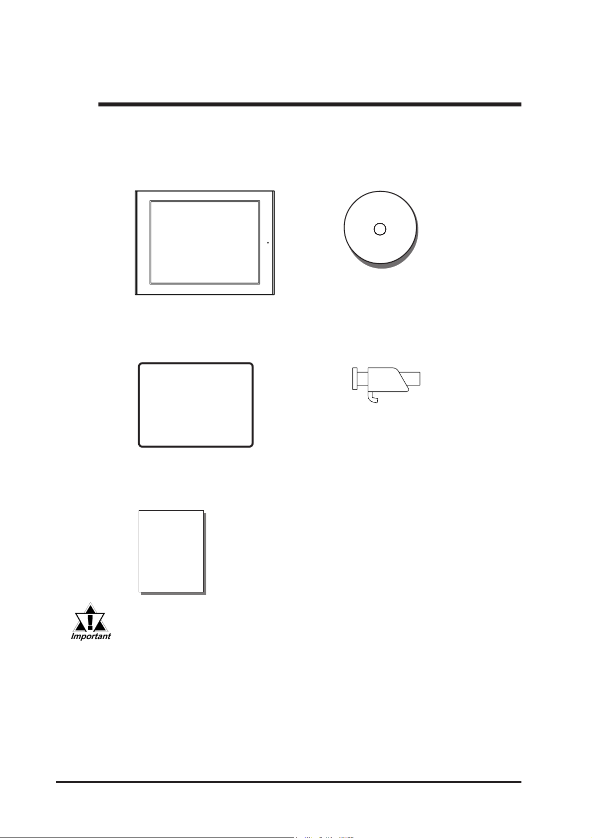
Package Contents
The FP unit's packing box contains the items listed below . Please check to be sure each
item is included and is not damaged.
FP unit (FP3700-T41)
Installation Gasket (1) Installation Fasteners (8: 4 x 2 set)
FP3700 User Manual CD-ROM (1)
User Manual
FP3700-T41 Installation Guide (1)
Installation
Guide
The Power Cord included in the FP unit's package is designed only for
AC100V or AC1 15V use. Any other voltage will require a dif ferent cord.
These items have all been carefully packed with special attention to product quality .
However, should you find anything damaged or missing, please contact your local FP
distributor immediately for prompt service.
AC Power Cord(1)
Cord Clamp(1)
USB Cable Strap(1)
xii FP3700-T41 User Manual

Preface
UL/c-UL (CSA) Application
The FP3700-T41 is a UL/c-UL (CSA) listed product. (UL File No.E220851)
This unit conforms as a product to the following standards:
UL508 Industrial Control Equipment
CAN/CSA-C22.2, No.14-M1995 Industrial Control Equipment
FP3700-T41 (UL Registration Model: 3180040-01 )
<Cautions>
• The FP must be used as a built-in component of an end-use product.
• This unit should be installed in the front face of a metal panel.
• If this unit is installed so as to cool itself naturally, be sure to install it in a
vertical panel.
Also, be sure that the FP unit is mounted at least 100 mm away from any
adjacent structures or equipment. If these requirements are not met, the heat
generated by the FP unit's internal components may cause the unit to fail to
meet UL/c-UL standard requirements.
CE Marking
The FP3700-T41 is a CE marked product that conforms to EMC directives and
Low Voltage directives EN55011 Class A, EN61000-6-2 and EN60950-1 First
Edition.
*For detailed CE marking information, please contact your local FP distributor.
<Cautions>
• The FP must be used as a built-in component of an end-use product.
• The FP is intended for indoor use only.
• This FP should be installed in the front face of a metal panel.
• If this unit is installed so as to cool itself naturally, be sure to install it in a
vertical panel.
Also, be sure that the FP unit is mounted at least 100 mm away from any
adjacent structures or equipment. If these requirements are not met, the heat
generated by the FP unit's internal components may cause the unit to fail to
meet standard requirements.
• When an end-user product will include the FP, be sure to design the FP unit's
power cut-off switch as a separate disconnect device and locate it where the
operator can easily reach it.
• Be sure the unit the FP is built into uses an EN60950-1 approved structure.
FP3700-T41 User Manual xiii

Preface
Memo
xiv FP3700-T41 User Manual
Chapter 1
Introduction
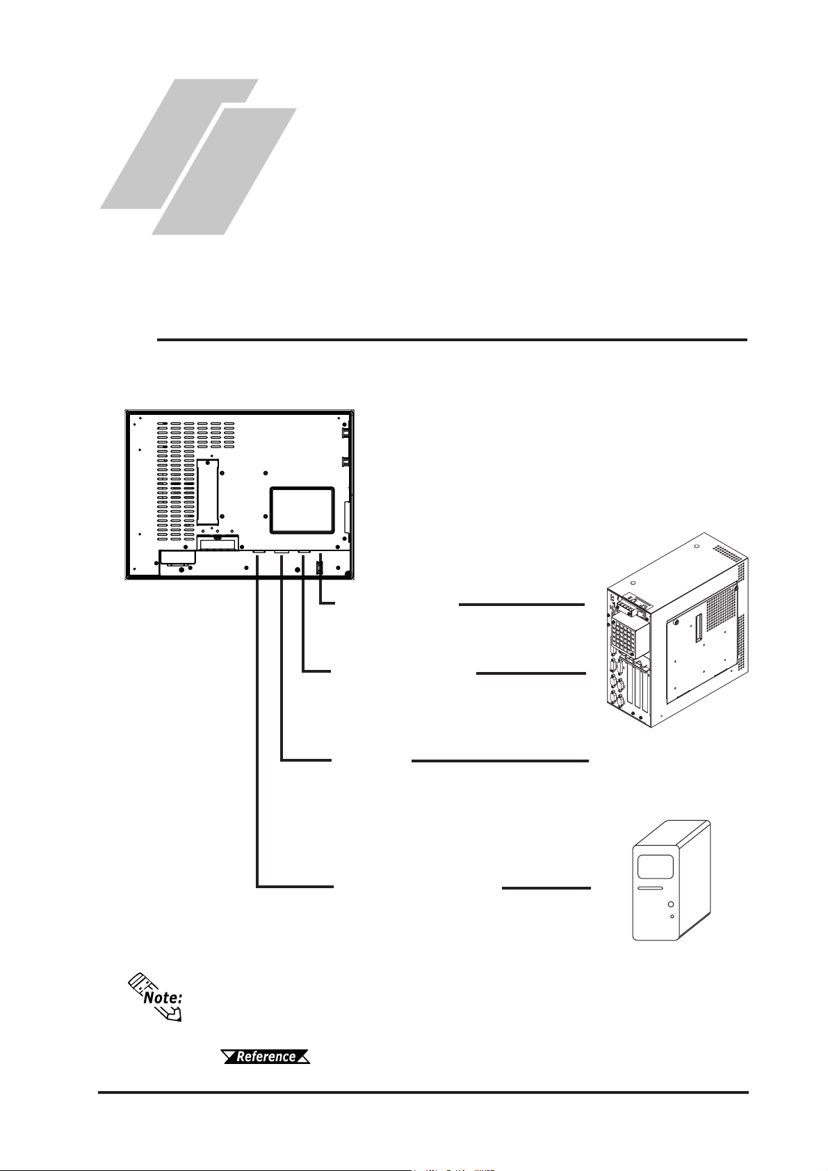
1.1 System Design
The FP can be connected to Pro-face's PS-2000B or to a Windows® compatible PC.
FP3700-T41 unit
1.1 System Design
1. System Design
2. Optional Equipment
USB Interface Cable
(FP-US00) (A-B type Cable<5m>)
For T ouch data and Command transmission
RS-232C Interface Cable
(FP61V-IS00-O<5 m>)
Straight Cable : Dsub 9-pin female
For T ouch data and Command transmission
DVI-D Cable
(FP-DV01-50 <5 m>, FP-DV01-100 <10 m>)
(XGA standard: DVI-D 24-pin)
For image signal output
* The FP-DV01-100 can be used only
when connected to a PS-2000B unit.
Analog RGB Interface Cable
(FP-CV02-45<4.5m>)
XGA standard : Dsub 15-pin male
For image signal output
The FP unit’s dip switches set the type of cable(s) used for sending touch data and
commands (USB or RS232C), and also for outputing image signals (DVI-D or Analog RGB).
PS-2000B or
Windows® compatible PC
3.3 Operation Mode Setup and Display Positioning
1-1FP3700-T41 User Manual
1.2 Optional Equipment
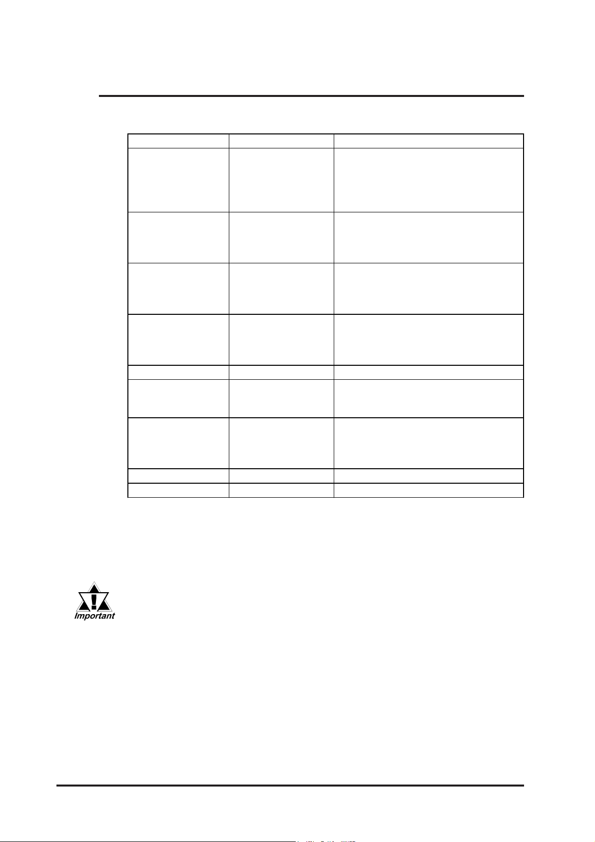
1.2 Optional Equipment
All optional items listed below are products of Digital Electronics Corporation.
Item Model Description
RS- 23 2C Ca ble FP 6 1V-IS00 -O
Anal og RGB Cabl e FP -CV 02-45
USB Cable FP-US00
DVI-D Ca ble
Inst al lat i on F asteners CA3-ATFALL-01 Metal i nst a l l ation fas teners.
Rubber Gas ket CA3-WP G 15-01
Sc reen P rot ect i on
Sheet
Backli gh t CA3-B LU15-01 Replac e m ent back l ight for t he FP.
Mouse E m ul ator V 2
Serial interface c abl e (5m) used for touc h
panel dat a t ran s mission between t he host
and the F P or comm a nd trans mission t o
the FP. This is a straight Dsub9 pin
female cabl e.
Anal og RGB in t e rfac e cabl e when i m ag e
signal is output to the FP from the host.
VGA s p ecifi cat i on s (Ds ub15 p i n m al e).
(4.5m)
USB i nterface c abl e (5m) us ed for touch
panel dat a t ran s mission between t he host
and the F P or comm a nd trans mission t o
the FP.A-B type cable.
Digital V i sual Int erface c ab l e used to s end
FP-DV01-50
FP-DV01-100
CA3-DFS15-01
*1
PL-TD000 Mouse E m u l ator software for t h e F P .
the image signal from the host to the FP.
*2
XGA s p eci ficatio ns (DV I-D 24-pi n m a l e). (5
m or 10 m)
Replac ement rubbe r gask et, u s e d when
installing the FP. Same as the FP's
original gask et .
Dis posabl e an d di rt res is tant
sheet for the FP's screen. The FP's
touch panel can be used wi th t hi s cover
sheet attached. (5 sheets/set)
*1 OS can be Windows®95, WindowsNT®4.0, Windows®98, Windows®2000 or
®
Windows
XP .
* 2The FP-DV01-100 can be used only when connected to a PS-2000B unit. When
using the FP-DV01-100, be sure to turn the PS-2000B's internal dipswitch 4 ON.
(When using the FP-DV01-50, turn this switch OFF.)
When you use the PL-TD000, hardware settings can not be automatically detected.
As a result, select the COM Port on your PC used to connect the FP unit
and enter the settings given in the FP manual for the Allocated I/O address and Interrupt.
1-2 FP3700-T41 User Manual
2.1 General Specifications
-10oC to +60
o
C
30%RH to 90%RH
(Non condensing, wet bulb temperature: 39
o
C or less)
Free of corrosive gasses
Pollution Degree 2
Free of corrosive gasses
10Hz to 25Hz 4.9m/s
2
X, Y, Z directions (30min.)
Noise Voltage: 1,500V p- p
Pulse Duration: 1
µ
s, 500ns , 50ns
Rise Time: 1ns
1. General Specifications
2. Functional Specifications
Chapter 2
Specifications
2.1 General Specifications
2.1.1 Electrical Specifications
Ra ted Vo ltag e
Rated Vol ta ge Range
Rated Fre quency
Rated Fre quency Range
Allowable Voltage Drop
Pow er Consum ption
In-Rush Current
Volta ge Endurance
Insulation Re sistanc e
3. Interface Specifications
4. Cable Diagrams
5. Names and Functions of FP
Parts
6. FP Dimensions
AC 100V t o AC 240V
AC 85V t o AC 264V
50/60 Hz
47 Hz to 63 Hz
20ms or less
120VA
30A or less
AC1500V 20mA for 1 minute
(between charging and FG terminals)
10MΩ or higher at DC500V
(between charging and FG terminals)
2.1.2 Environment Specifications
Ambient Operating
Temperature
Storage Temperature
Ambie nt Humidity
Air Pur ity (Dust)
Poll ution Degree
Corrosiv e Gasses
Vibra tion Re sistance
Noise Immunity
(via noise e m ulator)
Electro sta tic Di scharg e
Immunity
(the panel f ace should not incline more than 30
4kV (complies with E N 6100 0-4- 2 Level 3)
0oC to +50oC
o
)
FP3700-T41 User Manual
2-1

2.1 General Specifications
(
)
Natural air circulation
100Ω or less , or y ou r count r y's applicable st andar d
W395 mm [15.55in] x H294mm [11. 5 7in] x D6 0mm [2.36in]
7kg (15.4lb) or less
2.1.3 Structural Specifications
Grounding
Ratings
For front panel of installed unit
Externa l Dim ensions
Weight
Cooling Me thod
*1
The front face of the FP unit, installed in a solid panel, has been tested using
conditions equivalent to the standard shown in the specification . Even though
the FP unit’s level of resistance is equivalent to the standard, oils that should
have no effect on the FP can possibly harm the unit. This can occur in areas
where either vaporized oils are present, or where low viscosity cutting oils are
allowed to adhere to the unit for long periods of time. If the FP’s front face
protection sheet peels off, these conditions can lead to the ingress of oil into the
FP and separate protection measures are suggested. Also, if non-approved oils
are present, it may cause deformation or corrosion of the front panel’s plastic
cover. Therefore, prior to installing the FP be sure to confirm the type of conditions that will be present in the FP’s operating environment.
If the installation gasket is used for a long period of time, or if the unit and its
gasket are removed from the panel, the original level of the protection cannot be
guaranteed. To maintain the original protection level, you need to replace the
installation gasket regularly.
*1
Equivalent t o I P 65 f ( JE M 1030)
2-2
FP3700-T41 User Manual
2.2 Functional Specifications
2.2 Functional Specifications
2.2.1 Performance
Graphics
Displ ay Un it
Touch Panel I / F
Video I/ F
2.2.2 Display
Size
Type
Resolution
Dot P itch
Display colors
View i ng Angles
Brightness
Brightness Control
Contrast Control
Display area
Displ a y Modes
Backlight
Backlight Lifetim e
*1
*2
XGA ( 1024 X 768)
15 inch TFT XGA
Type
Resolution
Resistiv e Film (Analog)
1024 X 1024
Serial Interf ace (RS -2 32C)
Interface
USB Interface
Analog RGB Int er face
DVI-D Interface
38 cm (15 in. ) (Meas. diagonally )
TFT Active Matrix Color LCD
1024 (H) X 768 ( V) pixels (1pix el= R+ G+ B color bit s )
0.297mm [0.0 1 in. ] X 0.297mm [0.01 in. ]
16,777,216 colors (R / G/ B eight bits each)
160°(H)(TYP)/140°(V)(TYP )
220 cd/m2 (TYP)
Available
Available ( Analog RGB only)(when us ing analog RGB connection)
H 304.1 mm [11.9 7 in. ] X V 228.1 mm [8. 98 in. ]
640X400,640X480,720X400,800X600,1024X768
CCFL (Replaceable)
Backlight can be replaced by the user.
50,000 hours at an ambient temperature of 25
oC*3
*1 Dividing a completely white screen's brightness value by a completely dark
screen's brightness value yields a value greater than 10. This value is only for
reference and not a guaranteed value.
*2 The brightness at the central part of the screen when displaying a completely white
screen. This value is only for reference and not a guaranteed value.
*3 50% decreased brightness indicates the backlight needs to be replaced. This value
is only for reference and not a guaranteed value.
FP3700-T41 User Manual
2-3
 Loading...