

Digital Electronics Corporation PLB910-42, PLB911-42 Installation Manual
PLB910-42/PLB911-42
Installation Guide
WARNINGS
Follow the instructions given below to ensure the correct and safe use of the PL.
• To prevent an electrical shock, be sure to connect the power cord to the PL
before connecting it to the main power supply.
• A fire or electrical shock may result if voltages are used with the PL that are
beyond the specified range. Be sure to only use the specified voltage.
• Before opening the PL’s protective cover, be sure to turn the unit’s power OFF.
This is because the PL’s internal parts carry high voltages.
• If metal particles, water or other types of liquids contact any of the PL’s internal
parts, immediately turn the unit’s power OFF, unplug the power cord, and contact
your local PL distributor.
• Read and understand Chapter 4 “Installation and Wiring” thoroughly in order to
select an appropriate installation location for the PL.
• Before either plugging in or unplugging a board or interface connector, be sure to
turn the PL’s power OFF.
• To prevent a possible explosion, do not install the PL in areas containing flammable gases.
• The PL is not appropriate for use with aircraft control devices, aerospace equipment, central trunk data transmission (communication) devices, nuclear power
control devices, or medical life support equipment, due to these devices’ inherent requirements of extremely high levels of safety and reliability.
• When using the PL with transportation vehicles (trains, cars and ships), disaster
and crime prevention devices, various types of safety equipment, non-life support related medical devices, etc. redundant and/or failsafe system designs should
be used to ensure the proper degree of reliability and safety.
To Prevent Accidents
Follow the instructions given below to ensure the correct and safe use of the PL.
• Do not push on the PL’s screen too strongly, with either your finger or with a hard
object. Excessive pressure can scratch, crack or damage the screen. Do not use
a pointed object, such as a mechanical pencil or screwdriver, to press any of the
touch panel’s switches, since they can damage the display.
• If the screen becomes dirty or smudged, moisten a soft cloth with diluted neutral detergent, wring the cloth well, and wipe the display. Do not use thinner or organic solvents.
• Avoid storing and operating the PL in direct sunlight, high temperatures and humidity, and in areas where excessive dust and vibration will occur.
• Avoid using the PL in areas where sudden, extreme changes in temperature can occur.
This may cause condensation to form inside the unit, possibly leading to an accident.
• To prevent the PL from overheating, be sure its air circulation vents are clear and
clean, and keep the unit’s operation area well-ventilated.
• Avoid operating or storing the PL near chemicals, or where chemicals can come
into contact with the unit.
• The Digital Electronics Corporation cannot be held responsible or provide any
compensation for damage(s) caused by the loss of data stored in the PL™s hard
disk drive (HDD). It is therefore strongly suggested that all important data and
software be backed up regularly to an external data backup device.
• After turning OFF the PL's power, wait until the internal HDD stops spinning
before turning on the power again (approx. 5 seconds).
1

UL/c-UL (CSA) Application Notes
The PLB91*-4* is UL/c-UL 1950 recognized product. (UL File No. E171486). Please pay
special attention to the following instructions when applying for UL/c-UL approval for machinery which includes any of these PL units.
The PL conforms as a component to the following standards:
UL 1950, Third Edition, dated March 1,1998 (Standard for Safety of Information Technology
Equipment, including Electrical Business Equipment)
CSA-C22.2 No. 950-95 (Standard for Safety of Information Technology Equipment, including Electrical Business Equipment)
PLB910-4* (UL Registration Model No.: 2880056-02)
PLB911-4* (UL Registration Model No.: 2880056-01)
- Equipment with a PL mounted in it requires UL/c-UL evaluation for the combination of the PL
and equipment.
- The PL must be used as a built-in component of an end-use product.
- Use the PL indoors only.
- When connecting the PL’s power cable, be sure to use a cable that is appropriate for the current
and voltage used and that has conductive wires that are 0.75 mm2 or larger.
- When using the PL in an end-use product, be sure to install the PL unit's power cut-off switch
where the operator can easily reach it.
- Danger of explosion if backup battery is incorrectly replaced. Replaced only with same or
equivalent type recommended by the manufacturer. Dispose of used batteries according to the
manufacturer’s instructions.
- Be sure the unit the PL is built into uses a UL1950 compatible equipment structure.
CE Marking Notes
The PLGB91*-4* units are CE marked, EMC compliant products.
<Complies with the following Standards>
• Safety
EN60950
• EMI (EN50081-2)
EN55011 group1 (Class A)
• EMS (EN50082-2)
EN61000-4-2, EN61000-4-3, EN61000-4-4, EN61000-4-6, EN61000-4-8, ENV50204
If following requirements are not met, the PL may fail to meet EN60950 standard requirements.
• Equipment with a PL mounted in it requires UL/c-UL evaluation for the combination of the PL
and equipment.
• The PL must be used as a built-in component of an end-use product.
• Use the PL indoors only.
• When connecting the PL’s power cable, be sure to use a cable that is appropriate for the current
and voltage used and that has conductive wires that are 0.75 mm2 or larger.
• When using the PL in an end-use product, be sure to install the PL unit's power cut-off switch
where the operator can easily reach it.
• There is a danger of explosion if the backup battery is incorrectly replaced. This battery should
be replaced only with same or equivalent type recommended by the manufacturer. Dispose of
used batteries according to the manufacturer’s instructions.
• Be sure the PL unit's enclosure is an EN60950 approved sheet steel structure.
2

Package Contents
The PL package should include the following items:
!!
! PL Unit
!!
(PL-B910/PL-B911)
Be careful when
installing the PL
not to damage the
built-in HDD.
!!
! Floppy Disks
!!
– “PL-X900 Series Driver
& Utility Disk” for WIN95/NT (3)
– “PL-B910 Series Driver
& Utility Disk” for WIN98SE (3)
– “USB Touch Panel Control
Utility Disk” for WIN98SE (2)
!!
! Power Cord
!!
This cord is designed
only for AC100/115V
use. Any other voltage
will require a different
cable.
!!
! CD-ROM (1)
!!
contains PDF
manual file
!!
! Installation Brackets (1 set)
!!
and screws (6)
!!
! Installation Guide (2 -
!!
English and Japanese)
This
Guide
About The Manual
The CD-ROM contains the following PDF manual file.
PL-B910/B911 Series User Manual
Reading a PDF file requires installation of the Adobe Corporation’s Acrobat® Reader.
!Acrobat® Reader Installation:
To install the Acrobat® Reader software, follow the steps given below.
1) This software, in the form of a self-extracting file, is located in this CD-ROM in the folder
titled [reader]. Use the Explorer software to find the file [reader\ENG\ar405eng.exe], and
double-click on the file icon to begin the Reader installation.
2) After Installation begins, follow the instructions given on the Installation screens.
!Viewing the PDF manual:
To view the PDF manual contained in this CD-ROM, follow the steps given below.
1) Use the Explorer software to locate the file [manual\ENG\plb910e.pdf] in the folder
titled [manual].
2) Double-click on the PDF file's icon. Acrobat® Reader will automatically start and the
first page of the PDF manual will appear.
3
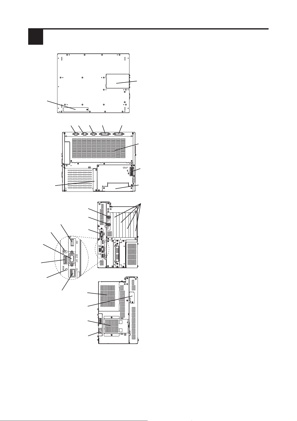
1 PL External Features
B
A
E
FCD
G
H
A : Front Face FDD Unit Attachment
Slot
B : Display Expansion Board Cover
C : RS-232C Connector (COM1)
D : RS-232C Connector (COM2)
E : RS-232C Connector (COM3)
F : Printer Connector (LPT1)
G : RAS Connector
H : Rear Maintenance Cover
I : Power Terminal Block
PL-B910
(4Slot)
J
PL-B910
(4Slot)
S
P
Q
R
U
J : IDE I/F Cover
I
A
E
K
L
T
V
W
K : Keyboard Connector
L : Mouse Connector
M : Expansion Slots
N : Side Mount FDD Slot
O : HDD/FDD Expansion Slot
P : Power LED
Q : Power LED Output Connector
R : Hardware Reset Switch
S : Standard Display Connector
(GVIF OUT)
T : Standard USB Connector (USB)
U : Dip Switches (SEL.)
V : Expansion Display Connector
PL-B910
(4Slot)
• Prior to attaching peripheral units to the PL, be sure the PL’s power cord
• To prevent an electrical shock, be sure to disconnect the PL’s power cord from
X
Y
Z
W : Half Cover
X : Analog RGB Connector Cover
Y : Filter Cover
Z : Power Switch
is disconnected from the main power supply.
the power supply before connecting the cord’s power terminals or any peripheral devices to the PL.
4
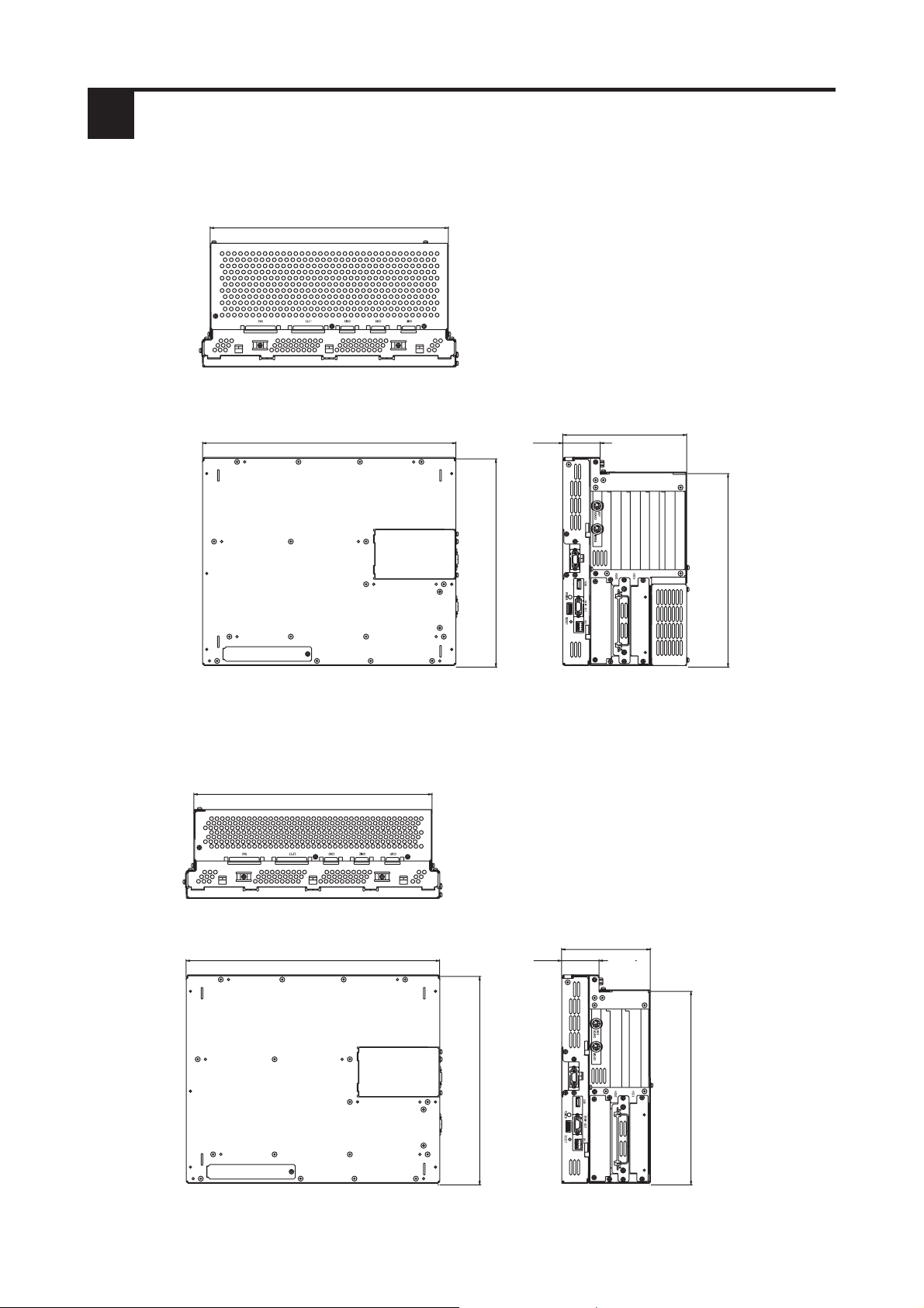
2 PL Dimensions
• PL-B910 General Dimensions
359 [14.13]
Top View
(Unit: mm [in.]- excluding projections)
374 [14.72]
Front View
• PL-B911 General Dimensions
359 [14.13]
13 [0.51]
325 [12.80]
(Unit: mm [in.]- excluding projections)
180 [7.09]
310 [12.20]
Side View
Top View
374 [14.72]
Front View
13 [0.51]
325 [12.80]
5
134 [5.28]
310 [12.20]
Side View
 Loading...