

Digital Electronics Corporation FP-570-TC-11, FR-570-TC21-24V Owner's Manual
FP-570-T User's Manual i
Other Symbols Used In This Manual
The list below describes the symbols used in this manual.
Explains a situation that requires a moderate amount of caution.
Indicates a word or phrase that has an additional explanation.
A reference point. Describes the word or phrase marked by the asterisk (*) and the corresponding number .
Reference pages on related topics.
This manual describes safety instructions for correct use of the FP unit. Please keep
this manual close at hand, and refer to it when necessary.
The following symbols are used throughout this manual to ensure the safe use of the
FP unit. Please make sure to follow all instructions given since they explain important safety points.
For the Safe And Correct Use of this Unit:
*1
!, "
Operational steps. Please follow these numbered steps in order to
perform the desired operation.
This mark warns of a situation that could either seriously
injure a person or lead to death if the instruction is ignored
and/or the unit is used incorrectly .
This mark warns of a situation that could either injure a
person or damage property if the instruction is ignored and/
or the unit is used incorrectly.
Warning
Caution

ii FP-570-T* User's Manual
Safety Instructions
For the safe use of this unit, please follow these guidelines:
Because of the ever present danger of electrical shock, be sure to unplug the power
cable from the FP unit before plugging the cable's other end into the wall.
Do not use power in excess of the unit's specified voltage range since it may cause a
fire or electric shock.
Because the FP unit is contains high voltage parts, an electric shock can occur when
disassembling the unit. Therefore, please be sure to always unplug the unit before
disassembling it.
Do not modify the FP unit in any way, since it may cause a fire or electric shock.
When changing the backlight, be sure to turn off the unit's power first, in order to
prevent an electric shock.
Do not use touch panel keys to perform life-threatening or vitally important safety
functions. Use separate mechanical switches for such keys.
If substantial amounts of metallic dust, water or liquids enter the FP unit, turn off the
power immediately, unplug the unit's power, and contact your local FP distributor.
When installing the FP unit, be sure to follow the instructions given in “Chapter 3.
Installation and Wiring," to insure it is done correctly.
Do not use the FP in an environment with flammable gas since it may cause an
explosion.
Warning
FP-570-T User's Manual iii
Do not press the screen's touch surface too strongly with either your finger or a hard
object, since the touch surface may be damaged.
When the surface of the display screen becomes dirty or smudged, clean the display
with a cloth soaked in a neutral detergent. Do not use paint thinner or organic solvent.
Do not press on the touch panel's face with sharp objects, such as a mechanical
pencil or screwdriver, since it might damage the panel.
Avoid using or storing the FP in direct sunlight, excessively dusty or dirty
environments, or where chemicals or their vapors are present in the air.
Avoid restricting the FP's natural ventilation, or storing and using the FP in an
environment that will increase the FP's internal temperature.
Please avoid using the FP in areas where sudden, large changes in temperature may
occur. These changes can cause condensation to form inside the unit, possibly causing
an accident.
The FP's LCD contains a strong irritant. If the panel is ever cracked and the LCD's
liquid contacts your skin, be sure to wash it with running water for at least 15 minutes.
If any of this liquid should enter your eye, be sure to flush the eye with running
water for more than 15 minutes, and see a doctor immediately.
The current brightness of the LCD screen will depend on the screen's current display
and the LCD's contrast adjustment. Any brightness variations that result are normal
for LCD displays.
There are minute grid-points on the LCD surface. These points are not defects.
Sometimes crosstalk (shadows appearing on extended display lines) will appear on
the display . This phenomenon is a common attribute of LCDs and is not a defect.
The displayed color will look different when viewed from an angle outside the speci-
fied view angle. This is also normal.
Displaying a single screen image for long periods of time can cause an afterimage to
remain. T o correct this, turn the unit OFF for 5 or 10 minutes, then ON again. This
phenomenon is a common attribute of the LCDs, and not a defect. To prevent this
effect, you can:
- use the Display OFF feature, if the same image is to be displayed
for a long period of time.
- change the screen display periodically to prevent the displaying of a
single image for a long period of time.
Safety Instructions
For the correct use of this unit, please follow these guidelines:
Notes on the FP's Liquid Crystal Display (LCD)
Caution

iv FP-570-T* User's Manual
1) It is forbidden to copy the contents of this manual, in whole or in part, except for the
user's personal use, without the express permission of the Digital Electronics Corporation
of Japan.
2) The information provided in this manual is subject to change without notice.
3) This manual has been written with care and attention to detail; however, should you find
any errors or omissions, please contact Digital Electronics and inform them of your
findings.
4) Please be aware that Digital Electronics is not responsible for any damages resulting
from the use of our products, regardless of article 3 above.
5) Specifications set out in this manual are for overseas products only, and, as a result,
some differences may exist between the specfications given here and the Japanese ones.
All Company/Manufacturer names used in this manual are the registered trademarks of
their respective companies.
© Copyright March 1997, Digital Electronics Corporation
Preface
Thank you for purchasing Digital’s TFT type color display panel, the 'FP-570-T*' (hereafter
referred to as the FP unit).
The FP unit is a TFT type color liquid crystal display monitor for IBM-PC compatible personal computers (VGA mode).
Please read this manual completely to insure the correct use and complete understanding of
the FP unit's functions. The FP's analog interface is designed for use with standard VGA
mode. Please be aware that this unit may not be able to be connected with nonstandard VGA
modes. For more details, please refer to this manual's "PC Connectivity Notes" section.
The term FP-570-T* refers to the following units:
FP-570-TC-11 (AC 100V type)
FR-570-TC21-24V (DC 24V type - with CE marking)
<Note>

FP-570-T User's Manual v
Table of Contents
For the Safe and Correct Use of this Unit ...................................................................i
W arning: Safety Instructions .......................................................................................ii
Caution: Safety Instructions ........................................................................................iii
Preface.........................................................................................................................iv
T able of Contents ........................................................................................................v
PC Connectivity Notes ................................................................................................ vii
Features of the FP-570-T*........................................................................................... ix
Package Contents ........................................................................................................ x
Chapter 1—Introduction
1-1 Connecting the FP to a PC...................................................................................1-1
1-2 Optional Equipment..............................................................................................1-2
Chapter 2—Specifications
2-1 General Specifications .......................................................................................... 2-1
1 Electrical Specifications ............................................................................................2-1
2 Environmental Specifications ....................................................................................2-1
3 Structural Specifications ............................................................................................2-1
2-2 Functional Specifications .....................................................................................2-2
2-3 Interface Specifications ....................................................................................... 2-3
1 Analog RGB Interface ...............................................................................................2-3
2 Serial Interface ...........................................................................................................2-4
2-4 Cable Diagrams....................................................................................................2-5
1 Pin Connections for the RGB Interface Cable..........................................................2-5
2 Pin Connections for the SIO Interface Cable ...........................................................2-6
2-5 Names and Functions of FP Parts .....................................................................2-7
2-6 Flat Panel (FP) Dimensions............................................................................... 2-8
1 FP570-T* External Dimensions ................................................................................2-8
2 Installation Brackets...................................................................................................2-9
3 FP Installation Dimensions ........................................................................................2-9
Chapter 3—Installation and Wiring
3-1 Installation .........................................................................................................3-1
3-2 Wiring .................................................................................................................. 3-5
1 Power Cable Connection ...........................................................................................3-5
2 Precautions: 100V FP-570-TC11 Power Supply ......................................................3-6
3 Precautions: Grounding .............................................................................................3-7
4 Precautions: Input/Output Signal Lines ....................................................................3-7

vi FP-570-T* User's Manual
3-3 Operation Mode Setup and Display Positioning ......................................................3-8
1 Operation Mode Setup and Adjustment..............................................................3-8
2 Adjusting the Touch Panel Display................................................................................. 3-9
3 Default Contrast Volume Setting and Adjustment........................................................... 3-10
Chapter 4—Touch Panel Commands
4-1 Command List .........................................................................................................4-1
4-2 Boot-up Initialization ..............................................................................................4-2
4-3 Touch Interface Data ...............................................................................................4-3
4-4 Touch Panel Commands..........................................................................................4-5
Chapter 5—Touch Panel Communication Programs
5-1 Bundled Software .................................................................................................... 5-1
5-2 Operation Environment ...........................................................................................5-2
5-3 Touch panel Input Drivers.......................................................................................5-3
1 ATPH.EXE (Touch Panel Handler)................................................................................. 5-3
2 CALIB.EXE (Touch Panel Data Calibration) ................................................................. 5-7
Chapter 6—Troubleshooting
6-1 Troubleshooting ...................................................................................................... 6-1
1 Possible Device Problems ............................................................................................... 6-1
2 No Display ....................................................................................................................... 6-2
3 Touch Panel Does Not Work ........................................................................................... 6-4
Chapter 7—Maintenance and Inspection
7-1 Regular Cleaning ..................................................................................................... 7-1
1 Cleaning the Display ....................................................................................................... 7-1
7-2 Periodic Check-Up ..................................................................................................7-2
7-3 Changing the 100V Unit's Backlight.......................................................................7-3
INDEX.............................................................................................i - iv

FP-570-T User's Manual vii
PC Connectivity Notes
Display Mode Size Dot Clock Range
V
G
A
Text Mode
720 x 400, 720 x 350 28.322MHz ±1%
Graphics Mode
640 x 480, 640 x 400, 640 x 350 25.175MHz ±1%
The FP unit's analog interface is designed for standard VGA mode. The number of
dots (pixels) displayed are as follows:
When the unit is used in VGA text mode, the far right side's 80 dots are
not displayed.
The display mode is designated using dip switch SW1-4.
Some types of VGA equipment may not be within the ranges specified above, and,
therefore, cannot be connected to the unit.
Also, if the user changes his PC's VGA board, there is the possiblity that the new
board may not be able to be connected to the FP.

viii FP-570-T* User's Manual
High Quality TFT Color LCD Display
This unit is equipped with a 10.4 inch TFT type color LCD. Its superior brightness
and wide viewing angle, not found in ordinary laptop type TFT LCDs, widens
your scope of applications.
The screen's maximum resolution is 640 x 480 pixels, and can display 260,000
colors.
Easy Installation In User’s Cabinets and Panels
The FP-570-T*'s slim, lightweight, and compact design make installation a snap.
It was designed specifically for use as your F A (Factory Automation) or OA (Office
Automation) system monitor. The flat, front panel meets the rigorous IP65F
standard, and, even without any protective cover, the flat panel is highly resistant
to both water and dust.
Flat Panel can be used as a VGA Display
Since the FP-570-T* is equipped with an analog RGB interface, it can be connected
to any PC with standard VGA mode. (The PC's clock frequency, however, must
be within the standard range)
Easy Operation With the Built In Touch Panel
The FP-570-T*'s built in touch panel is standard equipment, allowing touch panel
data to be output to a host PC via input/output commands and an RS-232C cable.
Ultra convenient for systems requiring both touch panel operation and monitoring.
Features of the FP-570-T*
The features of the FP-570-T* are as follows.
FP-570-T User's Manual ix
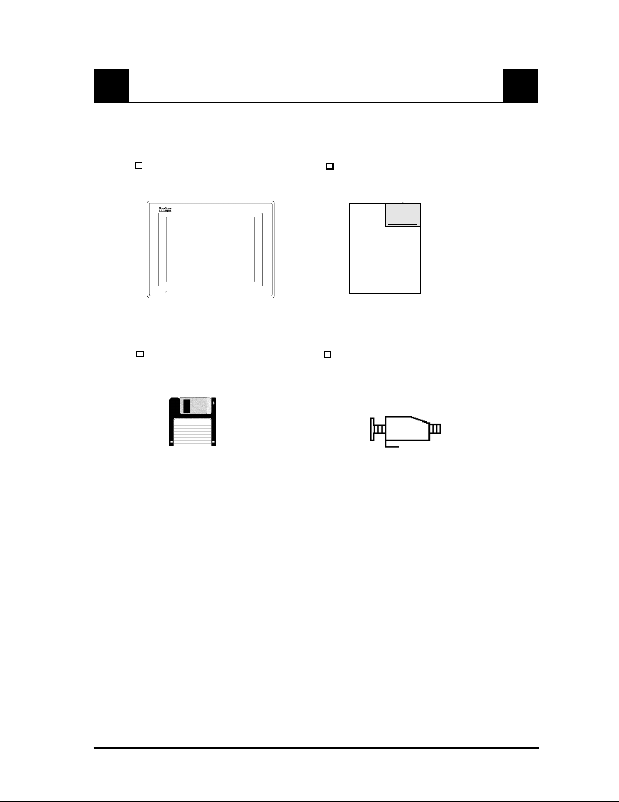
The FP's packing box contains the items listed below. Please check to be sure each is
included and is not damaged.
FP unit (FP-570-TC11 or FP-570-T* User’s Manual
FP-570-TC21-24V)
3.5 inch floppy disk Installation brackets (4)
(Contains Touch Panel programs)
These items have all been carefully packed with special attention to product quality.
However, should you find anything damaged or missing, please contact your local
distributor immediately for prompt service.
Package Contents
Pro-face
FP-570-T*
User's Manual
(100V/24V Units)
Digital

x FP-570-T* User's Manual
MEMO
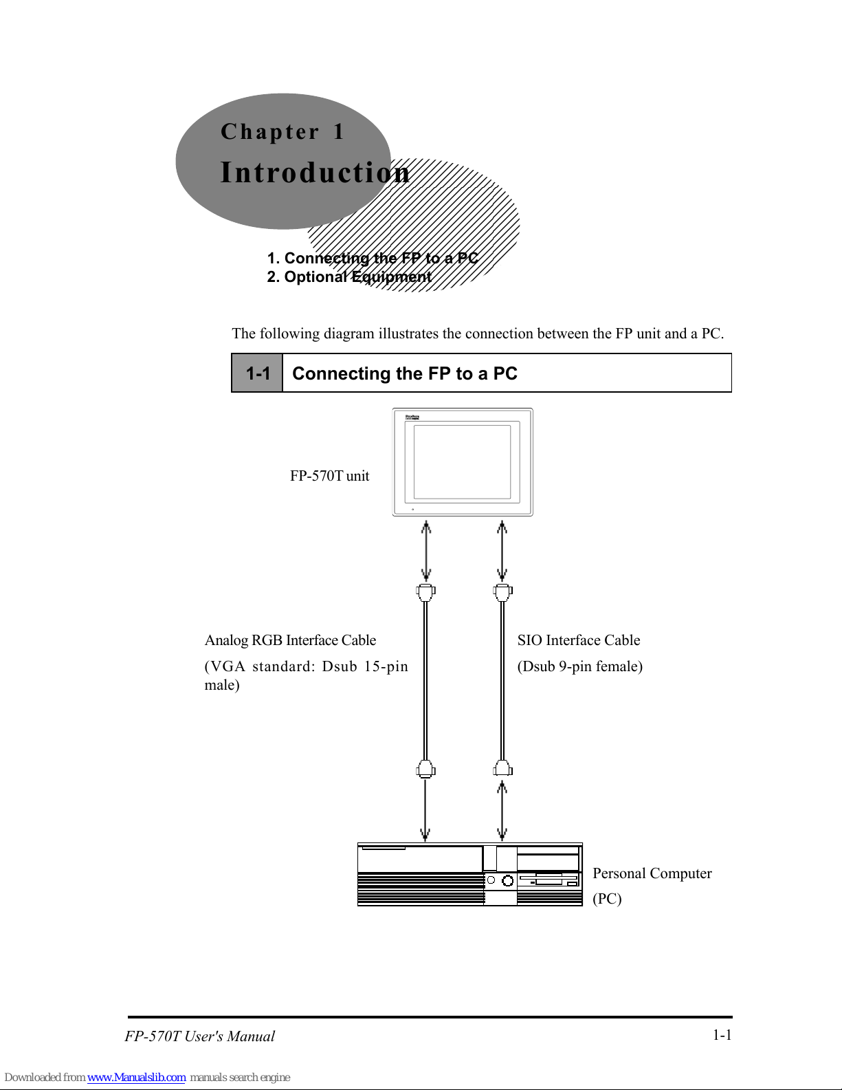
1-1 Connecting the FP to a PC
FP-570T unit
Personal Computer
(PC)
SIO Interface Cable
(Dsub 9-pin female)
Analog RGB Interface Cable
(VGA standard: Dsub 15-pin
male)
1-1
FP-570T User's Manual
The following diagram illustrates the connection between the FP unit and a PC.
Chapter 1
Introduction
1. Connecting the FP to a PC
2. Optional Equipment

Introduction
1-2 FP-570T User's Manual
1-2 Optional Equipment
All optional equipment listed below are products of Digital Electronics Corp.
Item Model Description
Maintenance
Parts
B acklight
Bulbs
G P570-BL00-MS
Replac em entBacklightbulbs
for100V unit(FP-570-TC 11)
Installation
Brackets
G P070-AT00-MS
Metalinstallation bracketsfor
FP-570-T*
Rubber
G asket
G P570-W P00-MS
Replacem en trubbergasket,
used w hen installing the FP.
Sam eas the FP 'soriginal
gasket.
Optional
Parts
Cover
Sheet
(Hard
ty pe)
G P570-DF10-0
Provides disposable scr een
protection from dustand other
elem ents. The touch panelc an
be used w iththe C overS heet
attached (5 sheets/set)
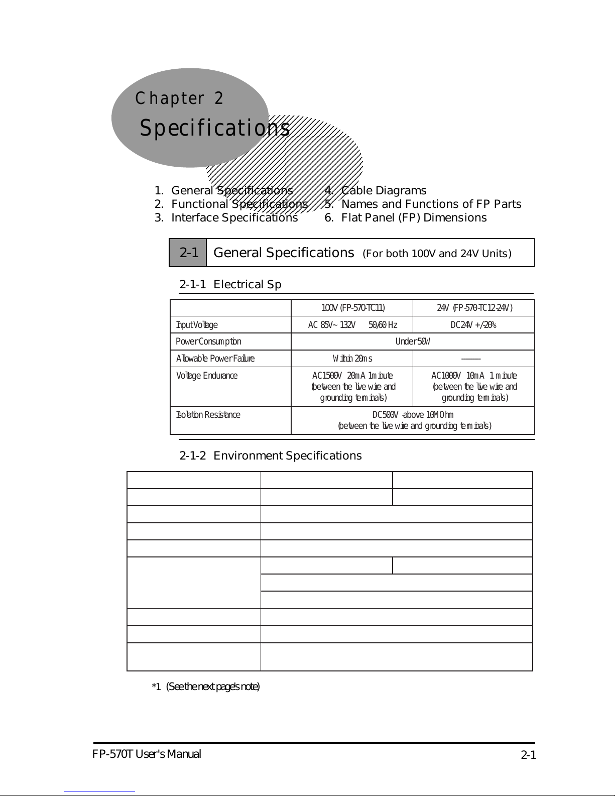
Chapter 2
Specifications
1. General Specifications 4. Cable Diagrams
2. Functional Specifications 5. Names and Functions of FP Parts
3. Interface Specifications 6. Flat Panel (FP) Dimensions
FP-570T User's Manual
2-1-2 Environment Specifications
2-1
*1 (See the next page's note)
100V (FP-570-TC11) 24V ( FP-570- TC12- 24V)
InputVol tage AC 85V~ 132V 50/ 60 Hz DC24V +/ -20%
PowerConsum pt ion Under50 W
Allowable PowerFailur eWithi n 20m s - -------Voltage Endur ance AC1500V 20m A 1m i nute
(between the live wire and
groundi ng t erminals)
AC1000V 10m A 1 m inut e
(between the live wire and
groundi ng t erminals)
Isol ation Resist ance DC500V - a bove 10 MOhm
(between the live wire and gr oundi ng t erminals)
2-1 General Specifications (For both 100V and 24V Units)
2-1-1 Electrical Specifications
100V (FP-570-TC11) 24V ( FP-570- TC12- 24V)
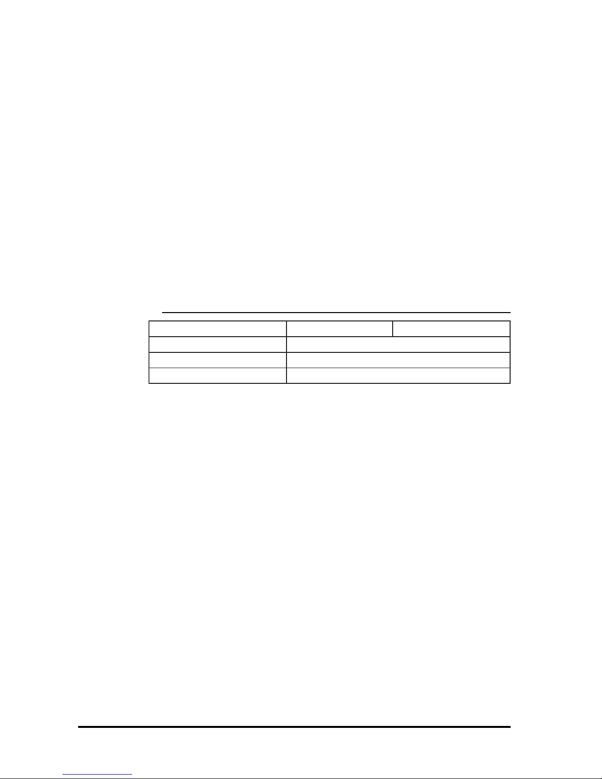
Operating T emperat ur e 0 ~ 40 degrees Celsi u s 0 ~ 45 degrees Celsi us
Storage T em peratur e-10~ 60 degrees Celsius
Ambien tHumidity 30 ~ 85% R H ( non- condensi ng)
Vibrat ion Endurance 2G s -10 t o25Hz (X,Y, Zdirec tions -30 m inut es each)
Noise E ndur ance N oi se vol tage: 12 00 Vp-pNoise voltage: 100 0 Vp-p
Pulse length: 1 m icr osec on d
Arise t ime (rise/ fall): 1 nanosecond
Atm ospher eNotim m une t ocorros ive gas
Ground Connect ion Les s than 100Ω,oryou rcou ntry's applicabl estandar d
Rating Equi valent toIP65f( JEM 1030)
and NEMA #250 T YPE4X/12
FP-570T User's Manual
Specifications
2-2
2-1-3 Structural Specifications
100V (FP-570-TC11) 24V ( FP-570- TC12- 24V)
ExternalDi m ensi ons 317W x 243H x 85D m m
Weight 3.5kg orless
Cooling S yst em Natur alai rcircul ation
The front face of the GP unit, installed in a solid panel, has been tested using conditions equivalent to the standard shown in the specification . Even though the GP
unit’s level of resistance is equivalent to the standard, oils that should have no effect
on the GP can possibly harm the unit. This can occur in areas where either vaporized
oils are present, or where low viscosity cutting oils are allowed to adhere to the unit
for long periods of time. If the GP’s front face protection sheet becomes peeled off,
these conditions can lead to the ingress of oil into the GP and separate protection
measures are suggested. Also, if non-approved oils are present, it may cause deformation or corrosion of the front panel’s plastic cover. Therefore, prior to installing the
GP be sure to confirm the type of conditions that will be present in the GP’s operating
environment.
If the installation gasket is used for a long period of time, or if the unit and its gasket
are removed from the panel, the original level of the protection cannot be guaranteed.
To maintain the original protection level, you need to replace the installation gasket
regularly.
*1 (Continued from previous page)
FP-570T User's Manual
Specifications
2-3
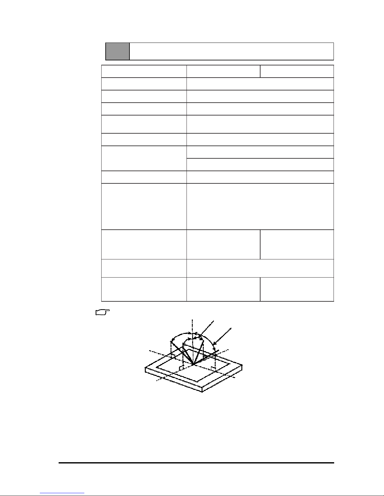
2-2 Functional Specifications (For both 100 V and 24V Units)
*1 Definition of V iewing angle
100V (FP-570-TC11) 24V ( FP-570- TC12- 24V)
Displ a y M ediaTFTcolorLCD
Displ ay C ol ors 260, 000 col ors
Resolut ion 640 x 480 pi xel s
ContrastA dj ustment Volum e adj ustm entavai labl e
(Adjust mentdiali slocated inrearofFP)
DotPitch ( mm) 0.33H x 0. 33W
Touch Panel Resol ution:1024 x 1024
Method: A nalog Resist ance Fi lm
Displ ay A r ea (m m ) 211W x 158H
Displ a y M ode
(sel ected withaswitch)
VGA textm ode: 720x400,720x350
*Farr ight side's 80dotsare notdispl a yed.
*400 or350 l ine di splay m odes aredisplayed i nthe
cent er.
VGA graphics m ode: 640x480,640x400,640x350
*400 or350 l ine di splay m odes aredisplayed i nthe
cent er.
Viewing A ngl e*1horizont al:(X)- 45 t o45
degrees
ver tical :(Y)-30 t o10
degrees
hor izont al:(X)-60 t o60
degrees
ver tical :(Y)-55 t o35
degrees
Int erfaces Anal og RGB Int erface,
SIOInt erface ( touch i nter face)
Back l ight CFL (undernor mal
tem perat ur es and hum idity,
lifespan = 20 ,000 hour s)
CFL (under nor mal
tem perat ur es and hum idity,
lifespan = 25 ,000 hour s)
-Y
+X
+Y
-X
Vertical angle (Y axis)
Horizontal angle (X axis)

FP-570T User's Manual
Specifications
2-4
2-3-1 Analog RGB Interface
2-3 Interface Specifications (For both 100V and 24V Units)
Pin Assignments and Signal Names for Analog RGB
Connector: Mini Dsub 15 pin type
Connector set screw: Inch type (4-40)
In VGA text mode, the far right side's 80 pixels do not display .
Selection of display mode is done via switch SW1-4.
Inputsignaltype Anal og RGB
Inputsi gnalchar act erist icImage signal :anal og RGB
Synchr onou s signal :TTL l ev el,negative t rue orpositive
true
Scanni ng t ype:non- int erlase
Adjust mentfunct ions Flickeradj ustment(8levels)
Anal og RGB con trastadj ustment
Horizont aldi splay positioning ( -16 ~ +15 pi xel s)
Vertict aldi splaypositioning ( -8 ~ +7 pixel s)
Display Mode Size DotClock R ange
V
G
A
TextM ode 720 x 400, 720 x 350 28. 322M Hz ±1%
Graphics M ode 640 x 480, 640 x 400,640 x 350 25. 175 MHz±1%
Pin
No.
SignalN am e Condition Pin Locat ion
1 Anal og R R signali nput
2 Anal og G G signali nput
3 Anal og B B signali nput
4 Reserved N C ( spar eforinput )
5Digitalgr oundi ng Di gitalsi gnalG N D
6ReturnR R signalG ND
7ReturnG G signalG N D
8ReturnB B signalG ND
9 Reserved N C ( spar eforinput )
10 Di gitalgr oundi ng Di gitalsi gnalG ND
11 R eserved NC ( spar eforinput )
12 Reser ved NC ( spar eforinput )
13 H.SYNC Horizont alsynchr onou s
signali nput
14 V.SYNC Verticalsynchr onou s
signali nput
15 Reser ved NC ( spar eforinput )
FP-570T User's Manual
Specifications
2-5
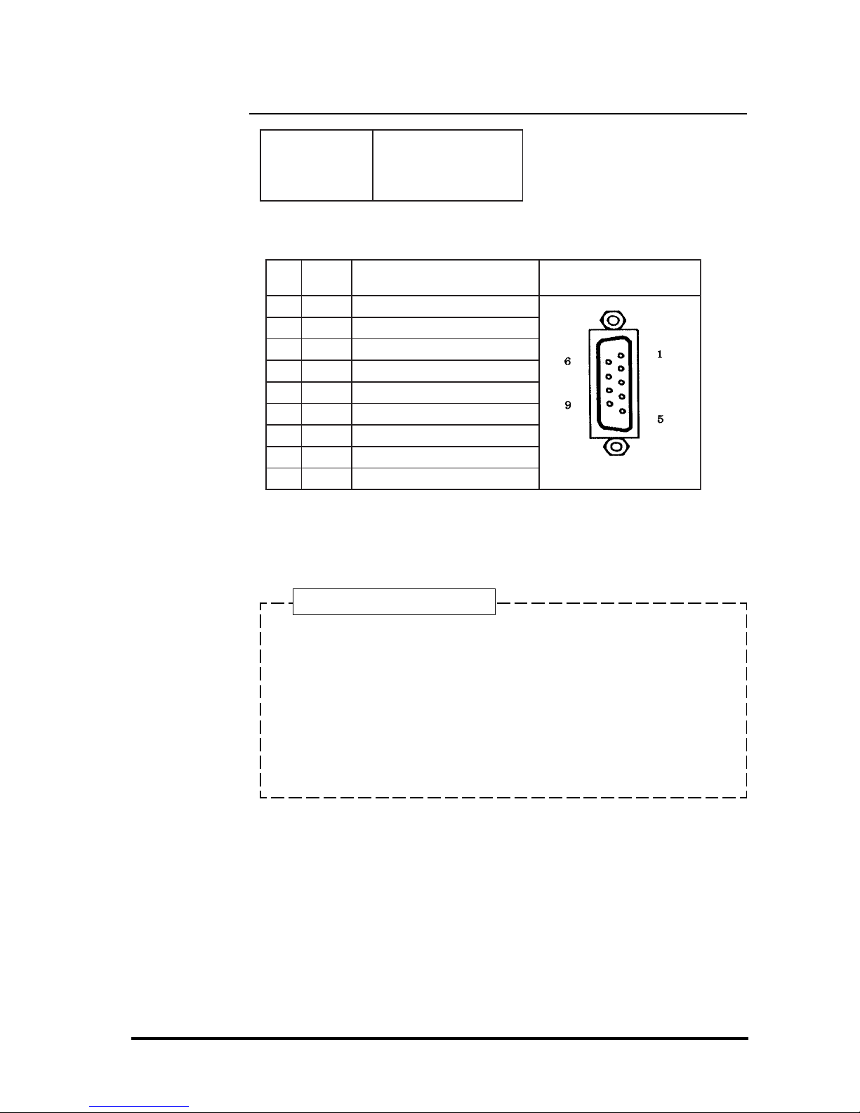
Concerning Signal Names
Signal names used for the serial interface on FP units are designed to
match the pin order used on most PC serial interfaces, so that a straight
cable can be used to connect the two. Therefore, connect each pin's
signal to the same signal name on the PC side.
For an example, pin #2 'RD' should be connected to the 'RD' input
terminal on the PC's connector.
Refer to section "2-4 Cable Diagrams" for each signal's direction.
2-3-2 Serial Interface
Pin Assignments and Signal Names for Serial Interface
Connector: Dsub 9 pin female
Connector set screw: Inch type (4-40)
Serial Interface
Baud r ate:9600 bps
Datalen gth:8 bi ts
Parity:none
Stop bit:1
Pin
No.
Signal
Name
Condition Pin Locat ion
1CDCarrierDetect(FP->Host)
2 RD Receive Dat a(FP->Host)
3SDSendData(FP<-Host)
4DTRDataTerminalR eady ( FP<-Host)
5GNDGround
6 DSR Da taSetReady(FP->Host)
7 RS RequesttoSend(FP<-Host)
8CSCleartoSend(FP->Host)
9 NC No connect ion
FP-570T User's Manual
Specifications
2-6
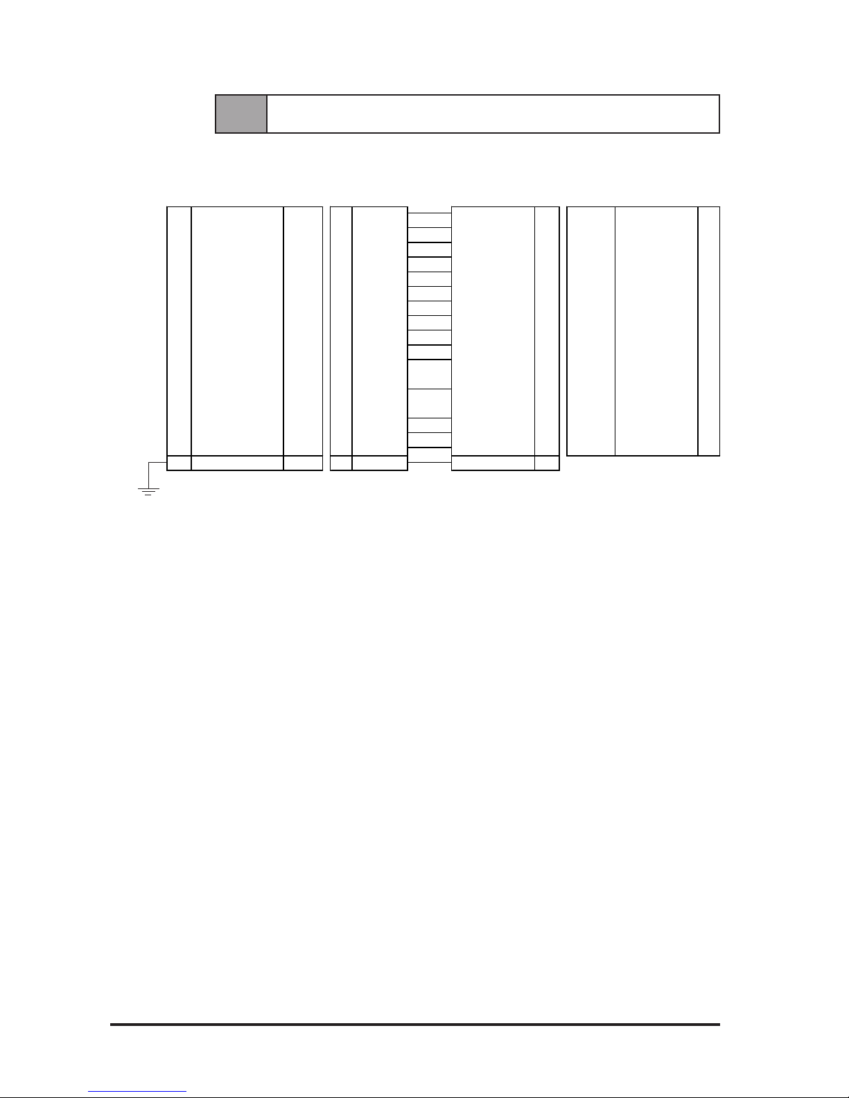
2-4 Cable Diagrams
RGB Interface Cable Pin Connections
FP side PC sideRGB cable
Signal names for the FP's RGB interface are designed to match the same pin
order as the RGB interface on personal computers.
1 ANALOG R INPUT 1 RED IN RED VIDEO 1 OUTPUT RED VIDEO 1
2 ANALOG G INPUT 2 GRN IN GRN VIDEO 2 OUTPUT GRN VIDEO 2
3 ANALOG B INPUT 3 BLU IN BLU VIDEO 3 OUTPUT BLU VIDEO 3
4 RESER VED - 4 NC NC 4 -- N C 4
5 DIGITAL GROUND - 5 GND GROUND 5 -- GROUND 5
6 RETURN R - 6 RED GND GROUND RED 6 -- GROUND RED 6
7 RETURN G - 7 GRN GND GROUND GRN 7 -- GROUND GRN 7
8 RETURN B - 8 BLU GND GROUND BLU 8 -- GROUND BLU 8
9 RESER VED - 9 NC NC 9 -- NC 9
10 DIGITAL GROUND - 10 GND GROUND 10 -- GROUND 10
11 RESERVED - 11 NC MONITOR 11 -- MONITOR 11
SENSE (COLOR) SENSE (COLOR)
12 RESERVED - 12 NC MONITOR 12 -- MONITOR 12
SENSE (COLOR) SENSE (COLOR)
13 H . SY NC IN PUT 13 HSY N HSY N 13 OU TPUT H SY N 14
14 V.SY NC IN PUT 14 VSY N VSY N 14 OUTPUT VSY N 15
15 RESERVED - 15 NC NC 15 -- NC 16
FG FG - F FG FG FG
 Loading...