

Digital Electronics PS3650A-T42, PS3650A-T42-24V, PS3651A-T42, PS3651A-T42-24V, PS3650A-T42S Installation Manual
...
1
PS-3650A/PS-3651A
Installation Guide
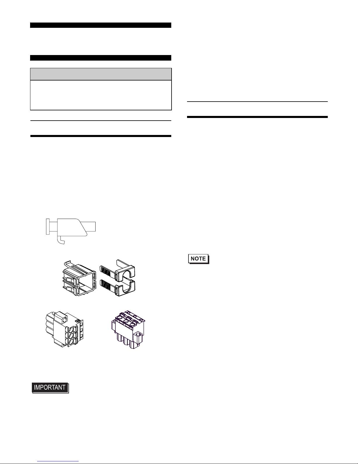
Package Contents
(1) PS-A Unit (1)
(2) English and Japanese Installation Guides
(one of each) <This Guide>
(3) Warning/Caution Information (1)
(4) Installation Gasket (1) (attached to the
PS-A unit)
(5) Installation Fasteners (Set of 4)
(6) USB Cable Clamp (2 ports) (2)
(7) Power Plug (1)
• Be careful when installing the PS -A not
to damage the built-in HDD.
This unit has been carefully packed, with
special attention to quality. However, should
you find anything damaged or missing,
please contact your local PS-A distributor
immediately.
When you order a PS-A unit built to your
specifications, the PS-A package should
include an Installation Guide for any optional
items included. Please use that guide to check
that all components are included in each
optional item's package.
About the Manual
For detailed information on PS-A series, refer
to the following manuals.
• PS-3650A/PS-3651A Series Hardware
Manual
• PS-3650A/PS-3651A Series
Reference Manual
• PS-3650A/PS-3651A Series
API Reference Manual
Manual can be downloaded from Pro-face
Home Page.
URL
http://www.pro-face.com/otasuke/
• The drivers and utilities for PS-A can be
downloaded from Pro-face Home Page.
This Installation guide is for the following
models:
• PS3650A-T42
• PS3650A-T42-24V
• PS3651A-T42
• PS3651A-T42-24V
• PS3650A-T42S
• PS3650A-T42S-24V
• PS3651A-T42S
• PS3651A-T42S-24V
Please refer to related manuals or installation
guides for PS-3650A/3651A Series that are
not listed above.
Caution
Be sure to read the “Warning/Caution
Information” on the attached sheet before
using the product.
AC type
(5.08mm[0.2in.]
pitch)
DC type
(7.62mm[0.3in.]
pitch)
2
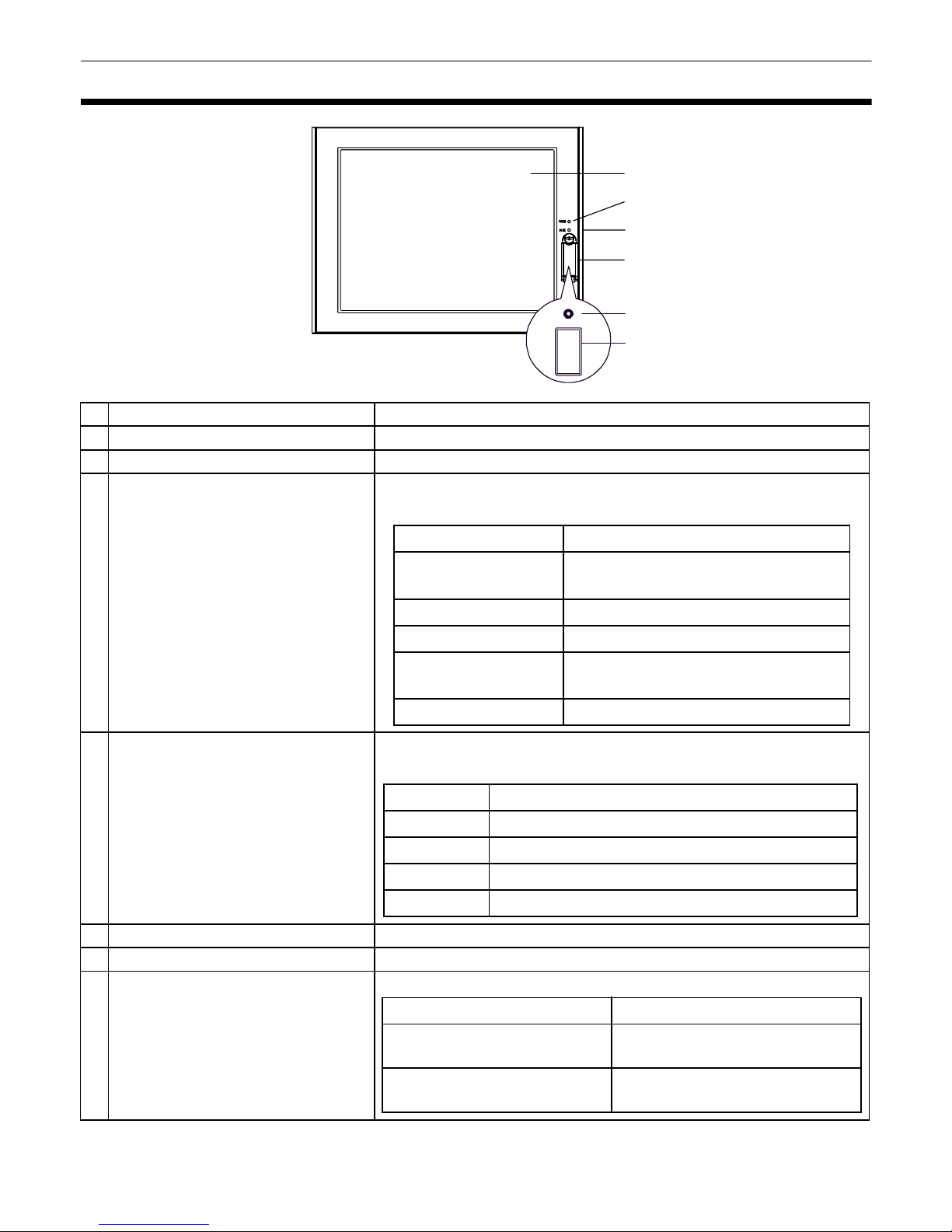
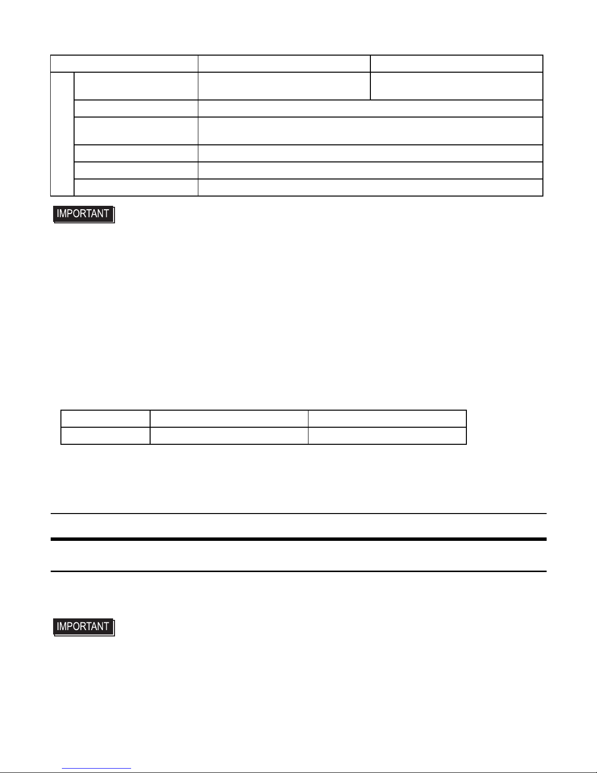
Part Names and Functions
Name Description
A Display Display Area
B Touch Panel User input is available by means of touching the panel.
C
Power LED / Status Lamp
(POWER)
The lamp shows the st atus of the PS-A’s power an d operat ion.
The display colors and their details are as follows.
D
DISK Access Lamp
(DISK)
The lamp shows the status PS-A’s DISK access and battery
operation. The display colors and their details are as follows.
E Front Cover
-
F
Hardware Reset Switch (R ES E T)
Restart PS-A.
E Front USB Interface (U SB )
1 port. Complies with USB 1.1. Uses a “TYPE-A” connector.
Front
A,B
C
D
E
F
G
LED PS-A Status
Green (lit)
Normal Operation
(power is on)
Green (blinking) Soft OFF state
Orange (lit) System monitor error
Orange/Red
(blinking)
Backlight burnout is detected
Not lit Power is OFF
LED PS-A Status
Green (lit) When HDD or IDE is accessed
Not lit When neither HDD nor IDE is accessed
Orange (lit) PS-A is in operation with backup battery
Red (lit) PS-A is in suspension with backup battery
Power supply voltage DC 5V ±5%
Output current
Each port: 500mA(max.),
5 ports total: 500mA(max.)
The maximum
communication dis tance
5m
3
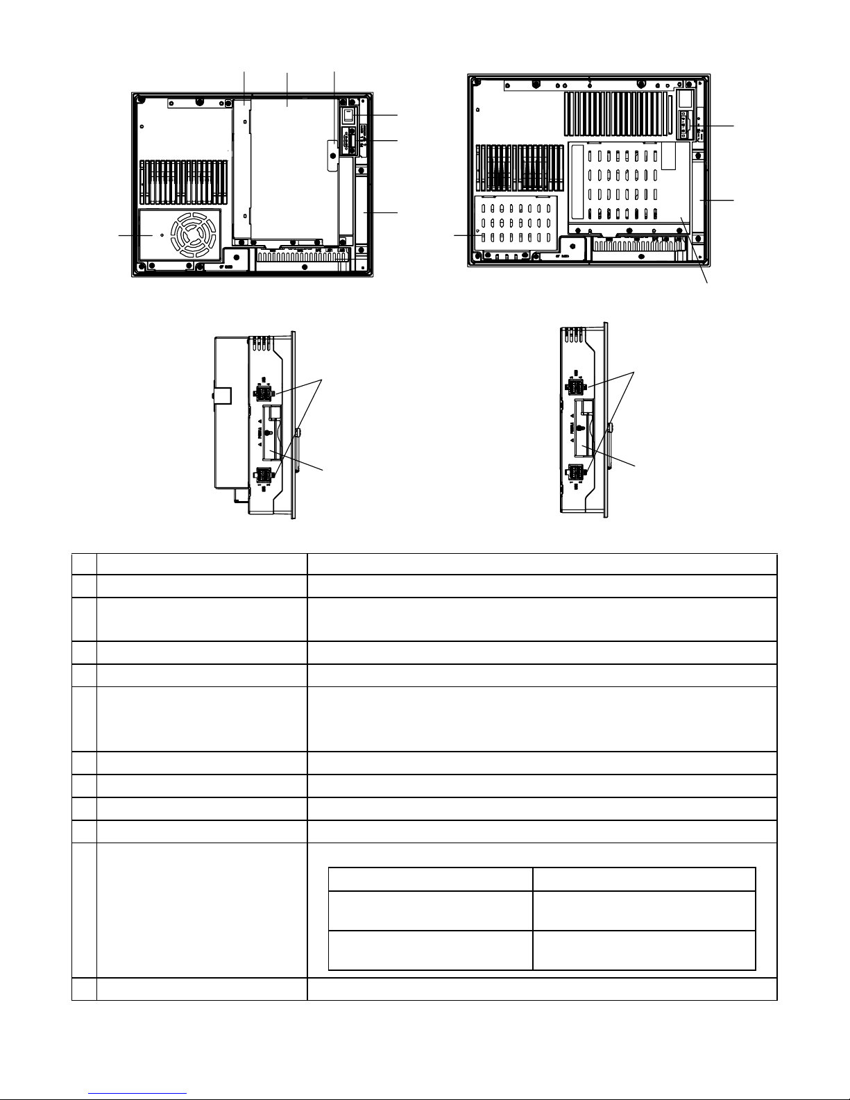
Name Description
H Power Switch Supported by AC type only.
I Power Connector
For connection, install a power plug, which is one of accessories,
to the power cable.
J Mask Cover
-
K Expansion Board Base PS-3650A Series only.
L Expansion Board Cover
The PCI board installati on in ter fa c e is lo cate d in the cover
opening.
PS-3650A Series only
M Expansion Board Supp or ter PS-3650A Series only
N Fan Unit PS-3650A Series only
O Memory Slot Cover PS-3651A Series only
P DISK Cover PS-3651A Series only
Q USB Interface (USB)
Side: comply with USB 2.0 (4 ports). “TYPE-A” connector.
R PCMCIA Slot Cover 1 slot under the cover. Complies with Type II.
PS-3650A Series
I
H
L
J
Q
R
N
Rear
Side
I
J
O
KM
PS-3651A Series
P
PS-3650A Series PS-3651A Series
Q
R
Power supply voltage DC 5V ±5%
Output current
Each port:500mA(ma x.),
5 ports total:500mA(max.)
The maximum
communication dis tance
5m
4
• When attaching peripheral units to the PS-A, be sure the PS-A's power cord is
disconnected from the main power supply.
General Specifications
Electrical Specifications
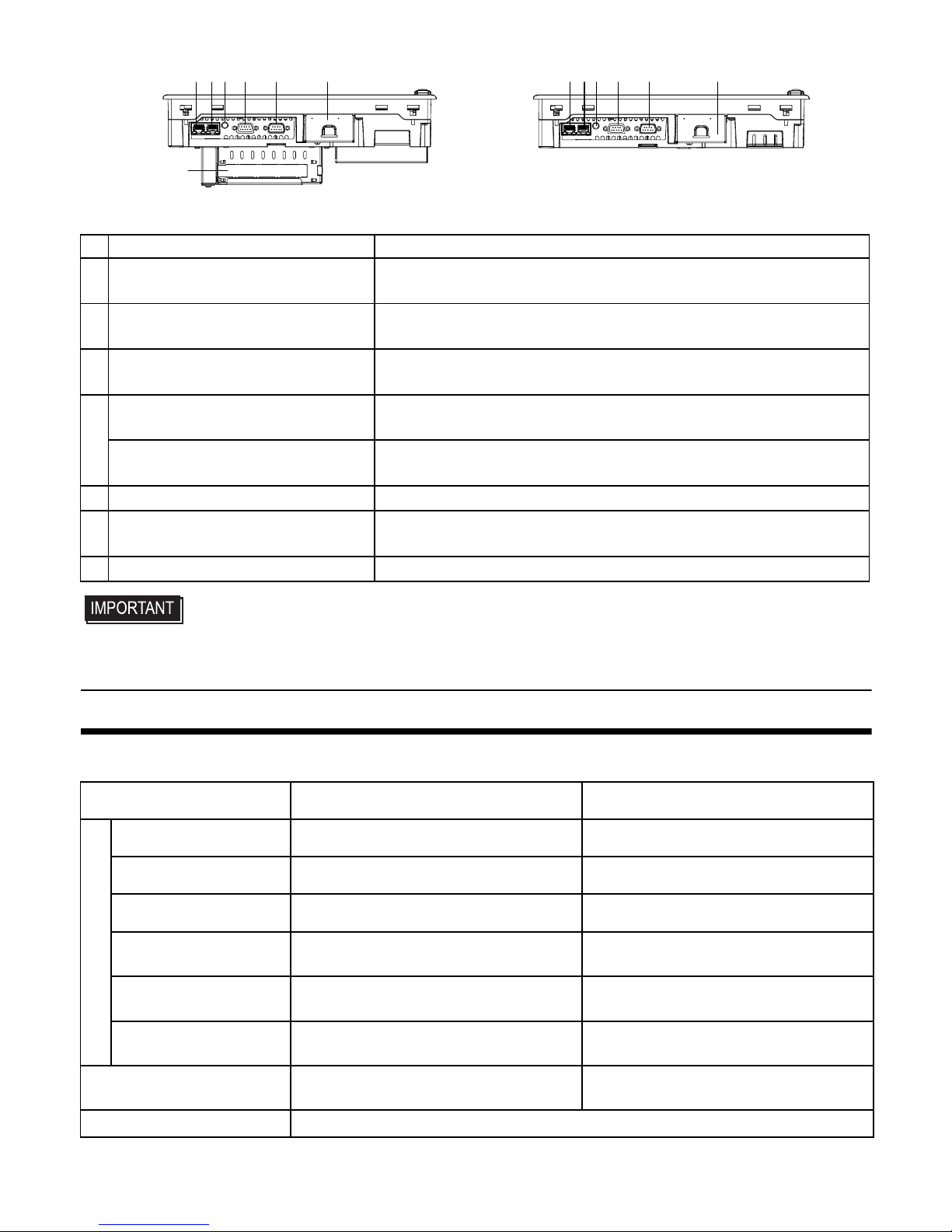
Name Description
S Ethernet Interface (LAN2)
10BASE-T/100BASE-TX /1000BASE-T Auto Cha ngeover . This
interface uses an RJ-45 type modular jack connector.
T Ethernet Interface (LAN1)
10BASE-T/100BASE-TX Auto Changeover. This interface
uses an RJ-45 typ e modular jack connector.
U
Speaker Output Interface
(SPEAKER OUT)
Mini jack connector.
V
RAS Interface (RAS)
RAS port type
2ch General-Purpose Input/Ou tput. D-Sub 9-pin socket type.
Serial Interface (COM2)
Serial 2 port type
D-Sub 9-pin plug. RS-232C compliant (RI Only).
W Serial Interface (COM1) D-Sub 9-pin plug. RS-232C, RS-422, RS-485 Changeover.
X CF Card Interface Cover
CF card interface i s under the cover . T yp e II-compliant slot, or T ype
1 x 1 slot.
Y Expansion Slot PS-3650A Series only.
AC Power Supply DC Power Supply
Power Supply
Input Voltage AC100/240V DC24V
Rated Voltage AC85 to 265V DC19.2 to 28.8V
Rated Frequenc y 50/60Hz
-
Allowable Voltage Drop
1 cycle or less (V oltag e drop interval
must be 1s or more.)
5ms or less
Power Consumption
PS-3650A Series: 110VA or less
PS-3651A Ser ies: 95VA or less
PS-3650A Series: 80W or less
PS-3651A Series: 40W or less
In-Rush current
(room temperat ure)
AC100V : 30A or less
AC240V : 50A or less
30A or less
Voltage Endurance
AC1,500V
20mA for 1minute
(between charging and FG te rminals)
AC1,000V
20mA for 1 minute
(between charging and FG terminals)
Insulation Resistance DC500V 10MΩ (min.) (between charging and FG terminals)
S
Bottom
PS-3650A Series
TU V W XSTUV W X
PS-3651A Series
Y
5
Environmental Specifications
• When using any of the PS-A’s optional devices, be sure to check that device’s
specifications for any special conditions or cautions that may apply to its use.
• Be aware that not only does the Hard Disk have a fixed lifetime, but that accidents
can always occur. Therefore, be sure to back up your Hard Disk’s data regularly, or
prepare another Hard Disk unit that can be used for backup.
• The Hard Disk lifetime given here may be reduced due to unforeseen environmental
factors, however, generally speaking, the disk should last for 20,000 hours (of
operation) or approximately 5 years, whichever comes first, at an operating
temperature of 20
°C and 333 hours of operation per month. (HDD access frequency
of 20% or less)
• Using the Hard Disk in an environment that is excessively hot and/or humid will
shorten the disk’s usage lifetime. A wet bulb temperature of 29
°C or less is
recommended. This is equivalent to the following data.
• In order to extend the lifetime of the ha rd disk, Pro-face reco mme nds you set the
Windows® XP (classic) [Control panel]-[Power Options]-
[Power Options Properties]-
[Power Schemes]-
[Turn off hard disks] selection to turn the hard disk off when the unit
is not being operated. A setting of 5 minutes is recomm ended.
DIP Switches
1. Changing Settings
To set the DIP switches which are on the PS-A’ s circuit board, remove the PS-A’s Fan Unit or
Memory Slot Cover.
• Use a screwdriver to loosen or tighten the screws. Be sure not to tighten screws too
tightly, since it may damage the unit.
• Be careful when removing o r insert in g any screws t hat t hey d o not f al l insi de the PS-A.
(1) Turn OFF the power switch of the PS-A and remove the power cable. Place the PS-A on a
flat, level surface facing the display face downwards.
PS-3650A Series PS-3651A Series
Physical
Surrounding Air
Temperature
0 to
50 °C
: without HDD
5 to
50 °C
: with HDD
0 to
50 °C
: without HDD
5 to
45 °C
: with HDD
Stor ag e Temperature - 20 to +60°C
Ambient Humidity
10 to 90% RH (Not condensing, wet bulb temperature: 39°C or less.
with HDD: 29°C or less.)
Stor ag e Hu m id i ty
10 to 90% RH (Not condensing, wet bulb temperature:39°C or less.)
Dust 0.1mg/m3 and below (Non-conducti ve le vel s)
Pollution Degree For use in Pollution Degree 2 environment
Temperature at 35°C at 40°C
Humidity no higher than 64% RH no higher than 44% RH

6
(2) Unscrew the screws (2) as you see on the following figure, then remove the Fan Unit or the
Memory Slot Cover.
2. DIP Switches Configuration
• Be sure to confirm what settings will be used by the other device and set the slide
switches accordingly. Failure to do so can result in a unit malfunction or damage.
• Whenever changing the PS-A swit ches, be sure to first turn the PS-A's power supply
OFF. Failure to do so can cause a PS-A malfunction.
Switch
Location
Switch Name Description
A System Set SW1 10-point DIP switch. For the switches details, see Table (1).
B
Serial Mode
Select SW
10-point DIP switch. Designates COM1 communication settings. For the switches details, see Table (2).
C System Set SW2 4-point DIP switch . F or the switches details, see Table (3).
PS-3650A Series PS-3651A Series
DIP Switch Locations

7
Factory setting is RS-232C. Only SW No.1 is ON.
Switch
No.
Description ON OFF
Notes
1 Used for the system. Reserved Reserved
Factory Settings: ON
2
Used for the system. Reserved Reserved
Factory Settings: OFF
3
Change Reset SW mode.
*1
*1 The PS-A restart s when pressing the switch in th e Sof t OFF st ate. Soft OFF means Windows® has
been shut down and the power is provide d only for the electric circuit t o boot system. Th is Soft OFF
State is different from System Standby set by Windows®.
Power
button
Reset SW Factory Settings: OFF
4
Sets up an enabled/disabled state
for the port exec ution control
function of hardware reset switch.
*1
Disabled Enabled
Factory Settings: OFF
5
Used for the system. Reserved Reserved
Factory Settings: OFF
6
Sets up an enabled/disabled state
for the front USB port execution
control function.
*2
*2 Setting up an enabled/disabled state for the USB port execution control function is available for only
Windows® . Make sure to disable the function of the setting when using another OS.
Disabled Enabled
Factory Settings: OFF
7
Used for the system. Reserved Reserved
Factory Settings: OFF
8
Cancellation function of pushing
two points on the touch panel
Enabled Disabled
Factory Settings: OFF
The middle point is not
considered to be tou c he d w h e n
the SW is ON.
It is considered to be touched
when the SW is OFF.
9
Used for the system. Reserved Reserved
Factory Settings: OFF
10
Changes COM1's # 9 pin
(RI <---> +5V).
Enabled only when RS-232C mode
+5V
Output
RI
Factory Settings: OFF
Table 1) System Set Switch 1
Switch
No.
Description ON OFF
RS-232C
RS-422 RS-485
1
Changes
COM1
's
communication
method.
RS-232C RS-422/RS-485 ON OFF OFF
2
Changes
COM1
's
communication
method.
RS-422/RS-485 RS-232C OFF ON ON
3
Changes
COM1
's
communication
method.
RS-422/RS-485 RS-232C OFF ON ON
4
Changes TX data's
output mode.
TX data output is
controlled via the
RTS signal.
TX data output is
NOT controlled via
the RTS s ignal.
(normally output)
OFF ON/OFF
ON/
OFF
*1

8
5
Switches the TX
termination resistance
ON/OFF.
Inserts termination
resistance of 220
Ω
between TXA and
TXB.
No termination OFF ON
ON/
OFF
*2
6
Switches the RX
termination resistance
ON/OFF.
Inserts termination
resistance of 220Ω
between RXA and
RXB.
No termination OFF ON
ON/
OFF
*2
7
Switches the shorting
of TXA and RXA ON or
OFF.
Shorts TXA and
RXA
(RS-485 mode)
No shorting
(RS-422 mode)
OFF OFF ON
8
Switches the shorting
of TXB and RXB ON or
OFF
Shorts TXB and
RXB
(RS-485 mode)
No shorting
(RS-422 mode)
OFF OFF ON
9
RTS Automatic control
mode
(enabled only when
RS-485 mode).
The data is
automatically
controlled via the
RTS signal.
The data is not
automatically
controlled via the
RTS signal.
OFF OFF
ON/
OFF
*1
10 OFF OFF
ON/
OFF
*1
Table 2) Serial Mode Select Switch
Serial Mode Select Switches (SW4 to SW10) operate as shown in the circuit diagram below.
*1 To enable RTS automatic control of th e TX outp ut drive r, set SW No. 9 and 10 ON, and set SW No.
4 OFF.
To enable control of the TX out put driver via RTS signal s, set SW No. 9 and 10 OFF, and set SW No.
4 ON
*2 If you use the termination resistance, base your settings on the connection specifications.
Switch
No.
Description ON OFF
RS-232C
RS-422 RS-485
RTS Automatic
control

9
External Interfaces
Serial Interface (COM1, COM2)
The PS-A unit side connector is a D-Sub 9
pin plug type.
• COM2 is an interface for the serial 2 port
type only.
• Do not connect any pins to [NC].
• Connect the FG terminal line to the shell.
• Always connect the #5 SG (Signal
Ground) of the PS-A unit to the
connected device, especially if the
connected device is also not isolated.
Failure to do so may damage the
RS232C/RS422/RS485 circuit.
• FG and SG terminals are internally
connected in the PS-A. When
connecting to another device, be sure
not to create an SG shorting loop in your
system.
COM1
COM1can be changed to RS-232C, RS-422 or
RS-485. (The factory setting is RS-232C.) To
change this setting, open the PS-A unit's FAN
Unit or Memory Slot Cover and set DIP switch
on the circuit board to the desired position.
Please refer to “DIP Switches” on page5 for
details.
Switch
No.
Description ON OFF
Notes
1
Changeover of a Master/Slave
setting for primary CF Card I/F.
Master Slave
Factory Settings: ON
2
Used for the system. Reserved Reserved
Factory Settings: OFF
3
Change Reset SW mode.
*1
*1 In SOFT OFF state, input to RAS Interface DIN1(+), will start the PS-A. RAS port type only.
Enabled Disabled
Factory Settings: OFF
4
Used for the system. Reserved Reserved
Factory Settings: OFF
Table 3) System Set Switch 2
Interfit Bracket #4-40 (UNC)
Pin
#
RS-232C
Signal Name
Description
1 CD Carrier Detect
2 RD(RXD) Receive Data
3 SD(TXD) Send Data
4 ER(DTR) Data Terminal Ready
5 GND Signal Ground (SG)
6 DR(DSR) Data Set Ready
7 RS(RTS) Request to Send
8 CS(CTS) Clear to Send
9
CI(RI)/+5V
*1
*1 To change pin 9’s RI/+5V setting, open
the PS-A unit's rear cover and set the
slide switch to the desired position.
Please refer to “DIP Switches” on p age 5
for details.
Called status display
/+5V Output
(Switching available)
Shell
FG
Frame Ground
(Common with SG)
Pin
#
RS-422
Signal Name
Description
1 RDA Receive Data A (+)
2 RDB Receive Data B (-)
3 SDA Send Data A (+)
4 NC No Connection

10
COM2
RAS Interface
The PS-A unit side connector is a D-Sub 9
pin socket type.
• RAS is an interface for RAS port type
only.
• Be sure to use only the rated voltage
level when using pin # 1 (+12V) for
external power output. Failure to do so
can lead to a unit malfunction or
accident.
• For the circuit diagram, refer to “PS-3650A/
PS-3651A Series Hardware Manual”.
5 GND Signal Ground (SG)
6 NC No Connection
7 SDB Send Data B (-)
8 NC No Connection
9 NC No Connection
Shell
FG
Frame Ground
(Common with SG)
Pin
#
RS-485
Signal Name
Description
1DATA +
Send/Receive
Data(+)
2 DATA - Send/Receive Data(-)
3 NC No Connection
4 NC No Connection
5 GND Signal Ground (SG)
6 NC No Connection
7 NC No Connection
8 NC No Connection
9 NC No Connection
Shell
FG
Frame Ground
(Common with SG)
Pin
#
RS-232C
Signal Name
Description
1 CD Carrier Detect
2 RD(RXD) Receive Data
3 SD(TXD) Send Data
4 ER(DTR) Data Terminal Ready
5 GND Signal Ground (SG)
6 DR(DSR) Data Set Ready
7 RS(RTS) Request to Send
8 CS(CTS) Clear to Send
9 CI(RI) Called status display
Shell
FG
Frame Ground
(Common with SG)
Pin
#
RS-422
Signal Name
Description
Interfit Bracket #4-40(UNC)
Pin
#
Signal
Name
Description
1 +12V
Output Current: 100mA
or less Output V oltage:
12V
±5%
2 DOUT0(+) Data out 0(+)
3DOUT1(+)
Data out 1(+)
4 DIN0(+) Data in 0(+)
5 DIN1(+) Data in 1(+)
*1
*1 This pin can be used as an input start or
external reset input of the RAS feature. The
factory setting is data input.
6 GND Ground
7 DOUT0(-) Data out 0(-)
8 DOUT1(-) Data out 1(-)
9 DINCOM Data in common

11
Installations
1. Installation Requirements
• For easier maintenance, operation, and
improved ventilation, be sure to install the
PS-A at least 50mm [1.97 in.] away from
adjacent structures and other equipment.
• Be sure that the surrounding air
temperature and the ambient humidity are
within their designated ranges. Surrounding
air temperature 0 to 50
°C: (with HDD:
PS-3650A - 5 to 50
°C, PS-3651A - 0 to
45
°C). Ambient humidity: 10 to 90%RH
(wet bulb temperature: 39
°C or less, with
HDD 29
°C or less).
When installing the PS-A on the panel of a
cabinet or enclosure, “Surrounding air
temperature” indicates both the panel face
and cabinet or enclosure’ s inter nal
temperature.
• Be sure that heat from surrounding
equipment does not cause the PS-A to
exceed its standard operating temperature.
2. PS-A Installation
(1) Create a Panel Cut following the dimen-
sions in the table below. Also, determine
the panel thickness according to the panel
thickness range with due consideration of
panel strength.
(2) Confirm that the installation gasket is
attached to the PS-A unit and then place
the PS-A unit into the Panel from the front.
• It is strongly recommended that you
use the installation gasket, since it
absorbs vibration in addition to
repelling water.
To replace the installation gasket, see
“PS-3650A/PS-3651A Series
Hardware Manual”.
50
[1.97]
50
[1.97]
50
[1.97]
50
[1.97]
[1.97]
50
[1.97]
50
[1.97]
50
Unit:mm[in.]
Panel Face
Inside Cabinet
50
[1.97]
30[1.18] 30[1.18]
Unit:mm[in.]
PS-A X Y
Panel
thickness
PS-
3650A
301.5
[
11.87
]
227.5
[
8.96
]
1.6[0.06]
to
10.0[0.39]
X
PS-A
Y
Unit: mm [in.]
4-R3[0.12]
or less
Panel
thickness
+1
-0
+0.04
-0
+1
-0
+0.04
-0

12
(3) Insert each fastener’s hook into the slot
and tighten it with a screwdriver. Insert
the installation fasteners securely into
the insertion slot recess. There are eight
insertion slots.
• Tightening the screws with too much
force can damage the PS-A unit.
• The necessary torque is 0.5N•m.
• Be sure to insert installation fastener s
in the recessed portion of an
installation fasteners hole. If the
fasteners are not correctly attached,
the PS-A unit may shift or fall ou t of the
panel.
Wiring
• To avoid an electric shock, prior to
connecting the PS-A unit’s power cord
terminals to the power terminal block,
confirm that the PS-A unit’s power
supply is completely turned OFF, via a
breaker, or similar unit.
• Supplying a power voltage other than
that specified can damage the PS-A
and the power supply.
• Since the DC power supply Type has
no power ON/OFF switch, be sure to
attach a breaker-type switch to its
power cord.
• When the FG terminal is connected, be
sure the wire is grounded.
• When the FG terminal is connected, be
sure the wire is grounded. Not
grounding the PS-A unit will result in
excessive noise. Use your country's
applicable standard for groun ding.
Power Cord Specifications
Use copper conductors only.
Wiring
When connecting the power cord, use the
following items when performing wiring.
(Items are made by Phoenix Contact.)
Insertion
Slots
Insertion Slot Recess
Hook the fastener
on the Recess,
Panel
Installation Fastener
PS-A
Hook
and secure the fastener
on the panel with a screw.
Power Cord
Diameter
0.75 to 2.5mm
2
(18 to 12 AWG)
Conductor
Type
Solid or Stranded Wire
*1
*1 If the Conductor’s end (individual) wires are
not twisted correctly, the end wires may either
short against each other, or against an electrode.
Conductor
Length
Recommended
Driver
SZS 0.6x3.5 (1205053)
Recommended
Pin Terminals
AI 0.75-10GY (3201288)
AI 1-10RD (3200182)
AI 1.5-10BK (3200195)
AI 2.5-12BU (3200962)
10mm [0.39in.]

13
• Accompanying AC type power supply
plug is CA7-ACCNL-01 from Pro-face or
FKC2.5/3-STF-5.08 is manufactured by
Phoenix Contact.
• Accompanying DC type power supply
plug is CA7-DCCNL-01 from Pro-face or
GFKC2.5/3-STF-7.62 is manufactured by
Phoenix Contact.
Connecting the Power Cord
(1) Confirm that the power is not supplied to
the PS-A unit.
(2) Push the Opening button with a small and
flat screw driver to open the desired pin
hole.
(3) Insert each pin terminal into its each hole.
Release the Opening button to clamp the
pin in place.
(4) After inserting all three pins, insert the
Power Plug into the Power Connector at
PS-A. Fix the plug with two (2) slot
screws.
• Confirm that all wires are connected
correctly.
• The torque required to tighten these
screws is 0.5 to 0.6N•m.
• To prevent the possibility of a terminal
short, use a pin terminal that has an
insulating sleeve.
1. Power Supply Cautions
• Input and Output signal lines must be
separated from the power control cables
for operational circuits.
• To improve the noise resistance, be sure to
twist the ends of the power cord wires
before connecting them to the Power Plug.
• The PS-A unit’s power supply cord should
not be bundled with or kept close to main
circuit lines (high voltage, high current), or
input/output signal lines.
• To reduce noise, make the power cord as
short as possible.
• If the supplied voltage exceeds the PS-A
unit’s range, connect a voltage transformer.
• Between the line and the ground, be sure to
use a low noise power supply. If there is an
excess amount of noise, connect a noise
reducing transformer.
• The temperature rating of field installed
conductors: 75°C only.
• Use voltage and noise reducing
transformers with capacities exce eding
Power Consumption value.
• Connect a surge absorber to handle power
surges.
• Be sure to ground the surge absorber
(E1) separately from the PS-A unit
(E2). Select a surge absorber that has
a maximum circuit volt age greater th an
that of the peak voltage of the power
supply.
Recommended
Pin Terminal
Crimp Tool
CRIMPFOX ZA3
(1201882)
L
N
FG
Opening Button
Black
White
Green/Yellow
AC power supply cord
DC power supply cord
Opening Button
Lightning Surge Absorber
E1 E2
FG
PS-A

14
2. Grounding Cautions
• Be sure to create an exclusive ground for
the Power Cord’s FG terminal. Use a
grounding resistance of 100Ω, a wire of
2mm
2
or thicker, or your country’s
applicable standard.
• The SG (signal ground) and FG (frame
ground) terminals are connected internally
in the PS-A unit.
When connecting the SG line to another
device, be sure that the design of the
system/connection does not produce a
shorting loop.
• The grounding wire should have a cross
sectional area greater than 2mm
2
. Create
the connection point as close to the PS-A
unit as possible, and make the wire as
short, as possible. When using a long
grounding wire, replace the thin wire with
a thicker wire, and place it in a duct.
3. Input/Output Signal Line Cautions
• All PS-A Input and Output signal lines
must be separated from all operating
circuit (power) cables.
• If this is not possible, use a shielded cable
and ground the shield.
• To improve noise immunity, it is
recommended to attach a ferrite core to the
power cord.
Other
Equipment
Exclusive Grounding
(BEST)
PS-A unit
Other
Equipment
Common Grounding (OK)
PS-A unit
Other
Equipment
Common Grounding
(Not OK)
PS-A unit

15
To prevent the USB cable
from coming off
When using a USB device, attaching the USB
holder to the USB Interface located on the
side of the PS-A unit prevents the USB cable
Interface from becoming disconnected.
• The USB holder cannot be attached to the
USB Interface located on the front of the
PS-A.
Attaching the USB Holder
(1) Before starting the procedure, lift up the
tab on both sides of the USB Holder and
remove the USB Cover.
(2) Attach the USB holder to the USB
Interface on the side of the PS-A unit.
Hook the upper pick of the USB holder
to the attachment hole of the PS-A unit
and then insert the lower pick as shown
below to fix the USB holder.
(3) Insert the USB cable into the USB
Interface.
(4) Insert the USB cover into the tab of the
USB holder to fix the USB cable.
In case of installing the second USB cable,
repeat the steps (3) and (4).
• When attaching the USB holder, be
sure to attach both USB covers, no
matter how many USB cables are
connected.
Removing the USB Holder
Remove USB Holder by the reverse
procedures to the attachment procedures.
(1) Lift up the tab of the USB holder and
then remove the USB cover.
(2) Remove the USB cable.
(3) Remove the picks pushing the USB
holder from both top and bottom and
then remove the USB holder from PS-A
unit.
Tab
Pick
USB Cable
Tab
USB Cover
(1)
(2)
Tab
USB Cover

16
Installation prerequisites for
standards
The following units are UL/c-UL listed products:
(UL/c-UL File No.E220851)
For the detailed certification's information,
refer to the Pro-face Home page.
<Cautions>
Be aware of the following items when
building the PS-A into an end-use product:
• The PS-A unit’s rear face is not approved
as an enclosure. When building the PS-A
unit into an end-use product, be sure to use
an enclosure that satisfies standards as the
end-use product’s overall enclosure.
• The PS-A unit must be used indoors only.
• Install and operate the PS-A with its front
panel facing outwards.
• If the PS-A is mounted so as to cool itself
naturally , be sure to install it in a vertical
panel. Also, it’s recommended that the PSA should be mounted at least 50mm
[1.97in.] away from any other adjacent
structures or machine parts. The
temperature must be checked on the final
product in which the PS-A is installed.
• For use on a flat surface of a Type 4X ( Indoor
Use Only) and/or Type 12 Enclosure.
• Type 4X (Indoor Use Only) and/or 12
Enclosure, when the hatch for Front USB
Port is secured with a screw .
T ype 1 Enclosure, when the hatch for Fron t
USB Port is open.
CE Marking
• PS3650A-T42, PS3650A-T42S, PS3651AT42, PS3651A-T42S units are CE marked
product that conforms to EMC directives
and Low Voltage Directives.
• PS3650A-T42-24V, PS3650A-T42S-24V,
PS3651A-T42-24V, PS3651A-T42S-24V
units are CE marked product that conforms
to EMC directives.
For the detailed information, please be
downloaded and refer the Declaration of
Conformity from Pro-face Home Page.
Digital Electronics Corporation
8-2-52 Nanko-higashi
Suminoe-ku, Osaka 559-0031
JAPAN
TEL: +81-(0)6-6613-3116
FAX: +81-(0)6-6613-5888
http://www.pro-face.com/
© Copyright 2009 Digital Electronics Corporation. All
rights reserved.
PFX104904F .PS365XA-MT03E-BTH
2012.3 JM/C
Product Model No.
UL/
c-UL
Registra-
tion Model No.
PS3650A-T42
3480801-02
PS3650A-T42S
PS3651A-T42
3480801-01
PS3651A-T42S
PS3650A-T42-24V
3480801-12
PS3650A-T42S-24V
PS3651A-T42-24V
3480801-11
PS3651A-T42S-24V
Inquiry
Do you have any questions about
difficulties with this product?
Please access our site anytime that
you need help with a solution.
http://www.pro-face.com/otasuke/
Please be aware that Digital Electronics
Corporation shall not be held liable by the
user for any damages, losses, or third
party claims arising from the uses of this
product.
Note
 Loading...