

FP790-T21
Installation Guide
WARNINGS
•T o prevent an electric shock, be sure to turn FP-790 unit’s (hereafter referred to as the “FP”) main
power supply OFF before attaching the power cord terminals to the FP unit’s power terminal strip.
•A fire or electrical shock may occur if voltages used with the FP are beyond the specified
range. Be sure to use only the specified voltage.
•Before opening the FP unit’s protective cover, be sure to turn the unit’s power OFF. This is
because the FP unit’s internal parts carry high voltages.
•To avoid fires or electrical hazards, do not modify the FP in any way.
•If metal particles, water or other types of liquids contact any of the FP unit’s internal parts,
immediately turn the unit’s power OFF, unplug the power cord, and contact your FP distributor.
• Prior to changing the FP unit’s backlight, be sure to diconnect the FP unit’s power supply.
•To prevent a possible explosion, do not install the FP in areas containing flammable gases.
•The FP is not appropriate for use with aircraft control devices, aerospace equipment, central
trunk data transmission (communication) devices, nuclear power control devices, or medical
life support equipment, due to these devices’ inherent requirements of extremely high levels of
safety and reliability .
•When using the FP with transportation vehicles (trains, cars and ships), disaster and crime
prevention devices, various types of safety equipment, non-life support related medical devices, etc. redundant and/or fail-safe system designs should be used to ensure the proper
degree of reliability and safety.
• Do not use the FP as a warning device for critical alarms that can cause serious operator
injury, machine damage or production stoppage. Critical alarm indicators and their control/
activator units must be designed using stand-alone hardware and/or mechanical interlocks.
CAUTIONS
•Do not push on the FPs screen too strongly, with either your finger or with a hard object.
Excessive pressure can scratch, crack or damage the screen. Do not use a pointed object,
such as a mechanical pencil or screwdriver, to press any of the touch panel’s switches, since
it can damage the display.
•If the screen becomes dirty or smudged, moisten a soft cloth with diluted neutral detergent,
wring the cloth well, and wipe the display. Do not use thinner or organic solvents.
•Avoid storing and operating the FP in direct sunlight, high temperatures and humidity, and in
areas where excessive dust and vibration will occur.
•Avoid using the FP in areas where sudden, extreme changes in temperature can occur. This
may cause condensation to form inside the unit, possibly leading to an accident.
•To prevent the FP from overheating, be sure its air circulation vents are clear and clean, and
keep the unit’s operation area well-ventilated.
•Avoid operating or storing the FP near chemicals, or where chemicals can come into contact with the
unit.
- 1 -
CE Marking Notes
The FP79*-2* units are CE marked, EMC compliant products.
<Complies with the following Standards>
• Safety
EN60950
• EMI (EN50081-2)
EN55011 group1 (Class A)
• EMS (EN61000-6-2)
EN61000-4-2, EN61000-4-3, EN61000-4-4, EN61000-4-5, EN61000-4-6,
EN61000-4-8, ENV50204
If the following requirements are not met, the FP may fail to meet EN60950
standard requirements.
• The FP must be used as a built-in component of an end-use product.
• Use the FP indoors only.
• When connecting the FP’s power cable, be sure to use a cable that is appropriate
for the current and voltage used and that has conductive wires that are 0.75 mm
larger.
• When using the FP in an end-use product, be sure to install the FP unit's power cut-
off switch where the operator can easily reach it.
• There is a danger of explosion if the backup battery is incorrectly replaced. This
battery should be replaced only with same or equivalent type recommended by the
manufacturer. Dispose of used batteries according to the manufacturer’s instructions.
• Be sure the FP unit's enclosure is an EN60950 approved sheet steel structure.
2
or
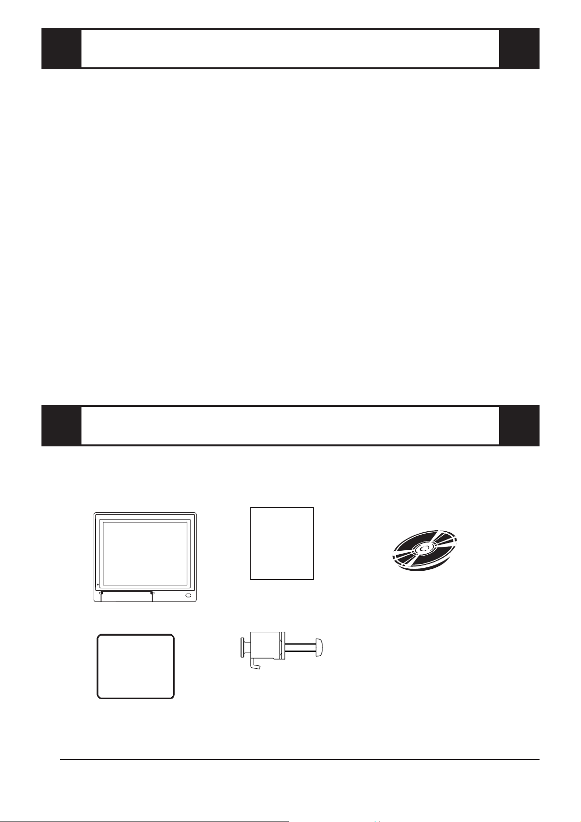
Package Contents
The FP package should include the following items:
FP Unit
(FP790-T21)
Installation Gasket
Installation Guide
(This document)
FP790-T21
Installation
Guide
Installation Brackets (12)
CD-ROM (1)
(Contains the FP User
Manual’s PDF file.)
These items have all been carefully packed with special attention to product quality. However,
should you find any item(s) damaged or missing, please contact your FP distributor immediately
for prompt service.
*1
*1 For a description and usage of the application programs stored in the CD-ROM, see the
“READM_E.DOC” file.
- 2 -

About The PDF Manual
The FP unit’s CD-ROM contains the following PDF manual file:
FP-790 Series User Manual (English/Japanese)
Reading a PDF file requires installation of the Adobe Corporation’s Acrobat
®
Reader.
Acrobat
To install the Acrobat
®
Reader Installation:
®
Reader software, follow the steps given below.
1) This software, in the form of a self-extracting file, is located in this CD-ROM
in the folder titled [reader]. Use the Explorer software to find the file
[reader\ENG\ar405eng.exe], and double-click on the file icon to begin the
Reader installation.
2) After Installation begins, follow the instructions given on the Installation
screens.
Viewing the PDF manual:
To view the PDF manual contained in this CD-ROM, follow the steps given below.
1) Use the Explorer software to locate the file [manual\ENG\fp790e.pdf] in the
folder titled [manual].
2) Double-click on the PDF file's icon. Acrobat
®
Reader will automatically start
and the first page of the PDF manual will appear.
- 3 -

1 FP External Features
A, B
J
Front
View
A: TFT type color LCD
The FP units’ output display. Data
from the host are displayed.
B: Touch panel
Used to switch screens and write data
to the host.
C: Power input terminal block
Used to connect the power supply
cable.
D: Status LED (Under development)
E: Setup switches (DIP switches)
Used to set the FP's operation mode.
F: MOUSE Connector (MOUSE IN)
Used to connect a mouse.
G: MOUSE Host connector (MOUSE
OUT)
Sends mouse output data from the FP.
Rear
C
View
Connects to the Host’ s PS\2 equivalent
Mouse input connector.
H: Serial I/F Connector (RS-232C)
Serial RS-232C interface. This
connects a serial cable to the FP, and
sends FP touch panel data to the Host,
HGF DE
Bottom
View
CI
and Host commands to the FP.
I: Analog RGB I/F connector
Analog RGB interface connector
J: Front Maintenance Cover (unused)
• Prior to attaching peripheral units to the FP, be sure the FP unit’s
power cord is disconnected from the main power supply.
• To prevent an electrical shock, be sure to disconnect the FP unit’s
power cord from the power supply before connecting the cord’s power
terminals or any peripheral devices to the FP.
- 4 -
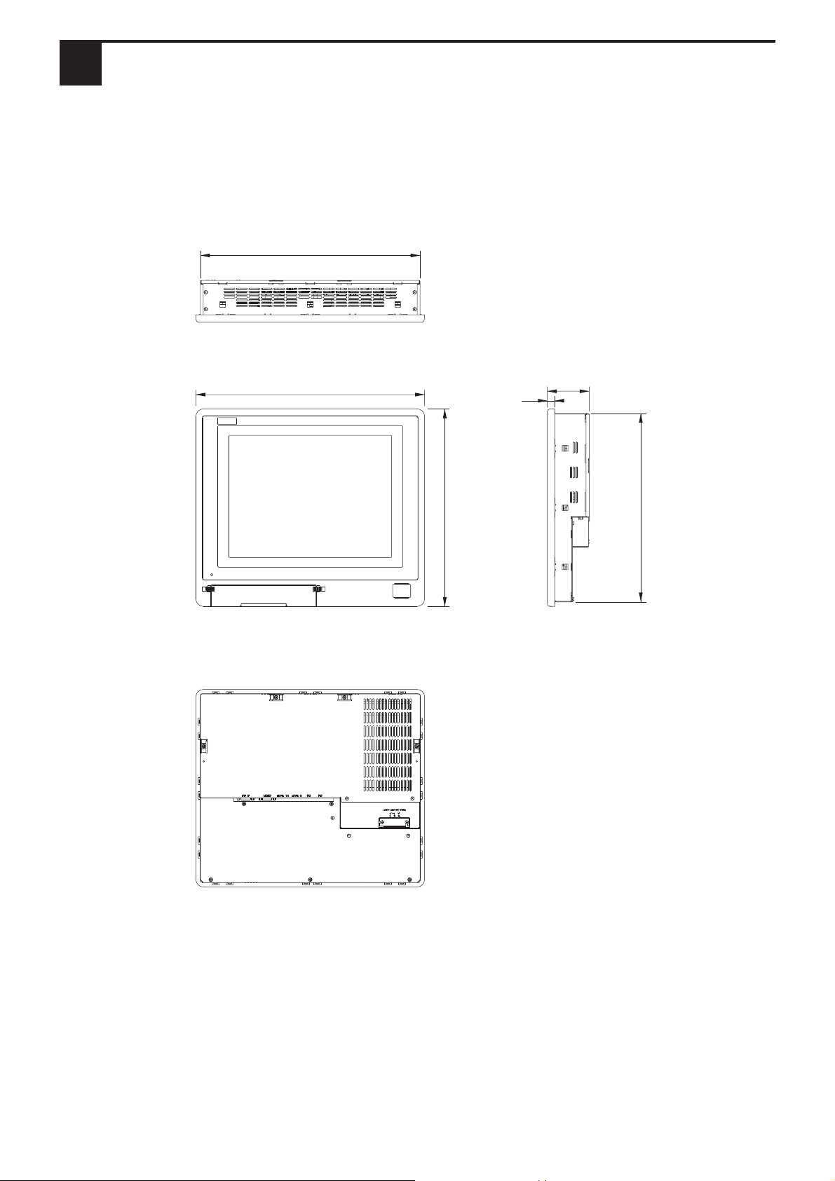
2 FP Dimensions
If detailed dimension information is needed, please contact your local FP distributor.
(Unit: mm [in.] - excluding projections)
389 [15.31]
Top View
405 [15.94]
Front View
14 [0.55]
74 [2.91]
334 [13.15]
350 [13.78]
Side View
Rear View
- 5 -

3 General Specifications
Electrical
Input Voltage
Rated Voltage
Frequency
Allowable Voltage Drop
Power Consumption
In-Rus h Current
Voltage Endurance
Insulation Resistance
Environmental
Ambient Operating
Temperature
(Cabinet interior and exterior)
Storage Temperature
Ambient Humidity 30% RH to 85% RH (no condensation)
AC 100V to AC 240V
AC 85V to AC 265V
50/60Hz
1 cycle or less
65VA or less
30A (normal), 45A (40
o
C)
AC 1500V at 20m A for 1 minute
(between charging and FG terminals)
Greater than 10MΩ at DC 500V
(between charging and FG terminals)
o
C to 40oC
0
o
C to 60 oC
-10
Air Purity Level
Atmosphere
Vibration Resistance
Noise Endurance
(via n oise simulator )
0.1mg/m3 or less ( f r ee o f conductive particles and dust )
800 to 1114 hP a ( 2000 meter s o r lower )
19.6m/s2 at 10Hz to 25Hz in X, Y, Z directions for 30 minu t es
Noise Voltage: 1500Vp-p
Pulse Width: 50ns , 500ns, 1µs
Rise Time: 1ns
Structural
Grounding
Less than 100Ω, or your countr y’s applicable standard.
Rating
*1
Cooling Method Via natural cooling
Weight
W 405mm [15.94in.] x H 350mm [13.78in.] x D 74mm [2.91in.]
External Dimensions
*1 The front face of the PL unit, installed in a solid panel, has been tested using conditions equivalent to
the standard shown in the specification . Even though the PL unit’s level of resistance is equivalent to
the standard, oils that should have no effect on the PL can possibly harm the unit. This can occur in
areas where either vaporized oils are present, or where low viscosity cutting oils are allowed to
adhere to the unit for long periods of time. If the PL’s front face protection sheet becomes peeled off,
these conditions can lead to the ingress of oil into the PL and separate protection measures are
suggested. Also, if non-approved oils are present, it may cause deformation or corrosion of the front
panel’s plastic cover. Therefore, prior to installing the PL be sure to confirm the type of conditions
that will be present in the PL’s operating environment.
If the installation gasket is used for a long period of time, or if the unit and its gasket are removed from
the panel, the original level of the protection cannot be guaranteed. To maintain the original protection level, you need to replace the installation gasket regularly.
Exclusive grounding only:
Equivalent to IP65f (JEM1030)
Less than 6.5kg (14.3lb)
(with HDD and FDD installed)
(excluding projections)
- 6 -

Display
Contrast Control Possible via adjustment menu
Effective Display Area (mm) W 279[10.98] X H 209[8.23]
Type TFT color LCD
Colo rs 260,000
Dot Pitch (mm) W 0.279 X H 0.279
640 X 480 (VGA)
Display Mo des
(set via selector switch)
Backlight
Touch Panel
Resolution (dots) 1024 X 1024
Type Resistive film (Analog)
External Interfaces
720 X 400 (US Text)
800 X 600 (SVGA)
1024 X 768 (XGA)
CFL
(under continuous 24 hour operation, lifespan = 10,000 hours)
Input Signal Analog RGB
Image Signal Analog RGB
Sync hronous Signal TTL Level, negative true or positive true
Scanning Type Non-interlaced
Analog RGB I/F
Serial I/F
(RS-232C )
Mouse I/F
Display Adjustment
Clock adjustment: -128 to 128
Phase adjus tment: 64 levels
Contrast Control via touch panel
Brightness Control via touch panel
Color Control via red, green, blue set tings
Horizontal Display
Positioning control
Vertical Display
Asyn chronous Transmis sion, RS 232C , Dat a Lengt h: 8 b its , S t op B it : 1, P arity:
None, Transfer S peed: 960 0bps
(MOUSE IN)
(MOUSE OUT)
PS /2 Int er face mini DIN 6-pin female
PS /2 Int er face mini DIN 4-pin female
- 7 -

4 Interface Specifications
Analog RGB Interface
Dsub15-pin (female)
5 4 3 2 1
10 9 8 7 6
15 14 13 12 11
Screw Size: (4-40): Inch Type
Pin No. Signal Name Condition
1 Analog R R signal input
2 Analog G G signal input
3 Analog B B signal input
4 NC Not Connected
5 NC Not Connected
6 Retu rn R R signal GND
7 Retu rn G G signal GND
8 Retu rn B B signal GND
9 NC Not Connected
Digital
10
Digital signal GND
Ground
11 NC Not Connected
12 NC Not Connected
Horizontal synchronous
13 H. SYNC
signal input
Vertical synchronous
14 V. SYN C
signal input
15 NC Not Connected
Recommended Connector: Mini Dsub 15 pin (JST Co.) KEY-15S-2A3F eqivalent
Connector set screw: Inch type (4-40UNC)
Cable: Digital Electronics Corporation RGB cable (FP-CV00, FP-CV01)
VESA Standard
Horizontal
Vertical
Dot Clock
Synch. Processing
Size
Display Mo de
Frequency
Frequency
Frequency
V, H
VGA 640×480 31.469 kHz 59.992 Hz 25.175 M Hz -,-
37.500 kHz 75.000 Hz 31.500 M Hz -,-
SVGA 800×600 37.879 kHz 60.317 Hz 40.000 M Hz +,+
46.875 kHz 75.000 Hz 49.500 M Hz +,+
XGA 1024×768 48.363 kHz 60.004 Hz 65.000 MHz -,-
56.476 kHz 70.069 Hz 75.000 M Hz +,+
60.023 kHz 75.029 Hz 78.750 M Hz +,+
US Text 720×400 31.469 kHz 70.087 Hz 28.322 MHz +,-
37.927 kHz 85.039 Hz 35.500 M Hz +,-
The allowable frequency fluctuation range in both the horizontal and
vertical frequencies is +/- 1%. If fluctuations exceed these ranges, the
FP will enter power save mode and the display will go blank.
- 8 -

RS-232C Interface (COM1/COM2/COM3)
This is an FP-790 Windows®-type Mouse Emulator RS-232C connector.
Signal
Name
Meaning
Dsub 9 pin (Male)
1 2 3 4 5
6 7 8 9
Screw Size: (4-40): Inch Type
Pin No.
1 CD Carrier Detect (FP->Hos t)
2 RXD Receive Data (FP->Host)
3 TXD Send Data (FP<-Host)
4 DTR Terminal Ready (FP<-Host)
5 GND Ground
6 DSR Data Set Ready (FP->Host)
7 RTS Ready to Send (FP<-H os t )
8 CTS Clear t o S end ( FP- > Ho st)
9 RI Not us ed
Recommended Connector: Mini Dsub 9-pin (JST Co.) JEY-9P-1A3F eqivalent
Connector set screw: Inch type (4-40UNC)
Cable: Digital Electronics Corporation SIO cable (FP-61V-IS00-0)
• Since all serial interface signals are the same on the PC side, use a
straight cable to connect the FP to the PC.
• The GND terminal is the signal ground. Be sure to connect the GND
terminal to other unit’s SG (signal ground).
- 9 -

Mouse Connector (MOUSE IN)
Mini - DIN 6 pin (Female)
6
4
2
Recommended Connector: Hoshi Electronics,Inc.: TCS7568-43-201 or equivalent
Recommended Mouse: Microsoft Corporation Microsoft mouse (PS/2 type)
5
3
1
• The mouse connection can be used for all equipment conforming to
the PS/2 mouse standards. However, Pro-face cannot guarantee the
FP will operate normally for all types of host and mouse combinations.
This unit was developed using the Microsoft Mouse
mouse products, the "IntelliMouse" and the "3 Button" mouse cannot
be used with this unit.
Pin N o. S igna l N ame
1Mouse DATA
2NC
3GND
4+5V
5Mouse CLK
6NC
SHIELD GND
®
. Microsoft's other
• When connecting the Mouse, be sure to use the Mouse Type Host
connector (MOUSE OUT) and the Host PC Mouse/Keyboard cable
(FP-CK01)
• Do not connect this cable when the power to the FP and the host (PC)
are both ON.
• After connecting the mouse, please re-start the Host unit's OS.
• When Windows 95 or Windows NT is used, set the “Control panel - Mouse Motion” feature to the standard pointer speed and hide the pointer trace.
Mouse Type Host Connector (MOUSE OUT)
Mini - DIN 4 pin (Female)
4
21
3
Pin N o. Signal N a m e
1GND
2 +V5
3 MOUSE CLK
4DATA
Recommended Connector: JST Corporation Mini DIN 4-pin (female) MD-S6100 or equivalent
• If the Host PC Mouse/Keyboard cable (FP-CK01) is not used with the
Mouse Type Host connector (MOUSE OUT), the mouse cannot be
used.
• Do not connect this cable when the power to the FP and the host (PC)
are both ON.
- 10 -

5 Installing the FP
Installation Procedures
Follow the steps given below when installing the FP.
Attaching the Installation Gasket
Even if the your FP unit’s Installation Gasket is not needed to prevent water from
entering the unit, the gasket also acts as a vibration absorber and should always be
attached. To install the gasket, place the FP face down on a soft surface and attach the
gasket to the rear side of the display face, in the plastic bezel’s groove (see picture
below).
Be sure the grooved face of the gasket is vertical.
• Before mounting the FP into a cabinet or panel, check that the Installation Gasket is attached to the unit.
• A gasket which has been used for a long period of time may have
scratches or dirt on it, and could have lost much of its dust and drip
resistance. Be sure to change the gasket periodically, or when
scratches or dirt become visible.
• The gasket must be inserted correctly into the groove for the GP’s
moisture resistance to be equivalent to IP65f.
• The upper surface of the gasket should protrude approximately 2mm
out from the groove. Be sure to check that the gasket is correctly inserted before installing the GP into a panel.
FP Rear Face
Installation
Gasket
• The gasket is flexible, but not elastic, and may tear if stretched too far.
Do not stretch the gasket around the ribs, only push.
• Be sure the gasket’s seam is not inserted into any of the unit’s corners, only in the straight sections of the groove. Inserting it into a corner may lead to its eventually tearing.
- 11 -

Create a Panel Cut
Create a panel cut for the FP, according to the dimensions given here. Two additional items, the installation gasket and installation fasteners are also required when
installing the FP.
+0.5
390.0
0
Attaching the Installation Fasteners
+0.02
[15.35 ]
0
4-R3 or less
+0.02
0
[13.19 ]
+0.5
0
335.0
The FP-790 is equipped with 12 installation fastener holes (3 on each side). Use the
drawings below to locate the top and bottom face holes and use a Phillips screwdriver
to tighen each fastener.
Installation Fasteners Installation Fasteners
Panel
FP
Top View
Installation
Fastener
Bottom View
• A torque of only 0.5 to 0.6 N•m is sufficient to tighten these
screws. Do not use too much force, since it may damage the
FP unit.
• If the dimensions of the Panel Cut are larger than those given
here, the panel can warp and distort the FP unit’s display.
- 12 -

6 Wiring the FP
WARNINGS
•To prevent an electric shock, be sure to turn FP unit’s main power supply OFF before attaching the power cord terminals to the FP unit’s power terminal strip.
• Be sure to use only the FP unit’s rated power level. Using any other level of power can
damage both the power supply and the FP unit.
• Since the FP is not equipped with the power switch, be sure to connect a breaker-type
power switch to the FP unit’s power cord.
• Use thick wire (2 mm2 max.) for the FP's power cable. Be sure that the cable is
twisted near the ring terminals.
• Use ring terminals with the following dimensions:
• To prevent the power terminals from being short-circuited due to a loose
screw, use ring terminals with insulating sleeves.
Rear of FP
LNFGLN FG
Power input
terminal block
Ring terminal *1
*1 L = Live line for AC input
N = Neutral line for AC input
FG = Ground terminal to be connected to the FP housing
Recommended ring terminal: V2-MS3 or equivalent (Manufactured by JST Co.)
- 13 -

7 Power Supply Cautions
When connecting the FP unit’s AC power terminals, please be aware of the following:
Constant
voltage
transformer
Insulating
transformer
AC100V to
AC200V
Main
power
source
Main power
source
AC 100V
to AC200V
source
I/O power
FP
power
source
I/O power
source
Twisted-pair
cable
Twisted-pair
cable
FP
power
source
T1
T2
FP
FG
FP
FG
FP
I/O device
FP
I/O
device
• If voltage fluctuations are expected to vary
beyond the specified range, connect a constant
voltage transformer.
• Use a low-noise power supply both between
the lines and between the FP and its ground. If
there is still excess noise, connect an insulating
transformer (noise-prevention type) .
Be sure any constant or insulating
transformer used has a capacity of
100VA or more.
• Wire the power cords of the FP, I/O devices,
and power supply devices separately.
• To improve noise immunity, it is recommended to attach a ferrite core to the power
cord.
• Isolate the main circuit (high voltage, large
current) line, I/O signal lines, and power cord,
and do not bind or group them together.
AC
Twisted-pair
cable
Main circuit
power source
E1
Lightning surge
absorber
FP
FG
E2
I/O
device
Power
device
• To prevent damage from lightning, connect a
lightning surge absorber.
• To prevent excessive noise, be sure to make
the power cord as short as possible.
• Ground the lightning surge absorber (E1) and the FP (E2) separately.
• Select a lightning surge absorber
which will not exceed the allowable circuit voltage, even when
the voltage rises to the maximum.
- 14 -

8 Grounding Cautions
(a) Dedicated Ground
FP
Other
device
(b) Shared Ground - allowed
FP
Other
device
(c) Shared ground - not allowed
FP
Other
device
• Set up a dedicated ground
*1
when using
the rear panel’s FG terminal.
• If a dedicated ground is not possible,
use a shared ground, as shown in figure
(b).
• The grounding wire should have a cross
sectional area greater than 2mm
2
. Create the connection point as close to the
FP unit as possible, and make the wire
as short, as possible. When using a
long grounding wire, replace the thin
wire with a thicker wire, and place it in
a duct.
*1Use a grounding resistance of less than 100Ω and a 2mm2 or greater thickness wire, or your
country’s applicable standard. For details, contact your local FP distributor.
- 15 -

9 Changing the Backlight
The FP-790 unit’s backlight is user replaceable.
For detailed information about changing the backlight, refer to the FP-790 User
Manual (sold separately) or the Replacement Backlight (sold separately) explanation.
The FP-790 uses the following backlight.
FP Mode l Backlight Model
FP790-T21 FP790-BL00
Be sure to use only Pro-face’s recommended backlight. Use of any other
backlight can lead to an accident or FP unit malfunction.
Note
Be aware that the Digital Electronics Corporation shall not be held liable for any real or estimated
damages or losses, or third party claims resulting from the use of this product.
© 2001 Digital Electronics Corporation. All rights reserved.
055524K .FP790-MT01-PROE
- 16 -
 Loading...