

Digital Dream UC300 User Manual
Mach3 USB Motion Controller
UC300
User’s Manual
The version of 20180925
Digital Dream CNC Co,. Ltd.
www.ddcnc.com

Contents
1. Brief Description of the UC300 Motion Controller
2. Safety Notes
5.2 Stepper/Servo Motor Control Interface Connection
5.3 Spindle Control Output Port
3. Physical Installation of the device
5. Wiring and Ports Description
4. Controller UC300 Power Solution
5.9 Power Supply for Controller System and Power Supply for IO Port
5.5 Function Switch for MPG and Connection for MPG
1
1
2
4
5
5
6
7
9
10
10
13
13
14
14
15
16
17
20
●●●●●●●●●●●●●●●●●●●●●●●●●●●●●
●●●●●●●●●●●●●●●●●●●●●●●●●●●●●●●●●●●●●●●●●●●●●
3
●●●●●●●●●●●●●●●●●●●●●●●●●●●●●●●●●●●●●●●●●●●●●●
●●●●●●●●●●●●●●●●●●●●●●●●●●●●●●●●●●●●●●●●●●●●●●●●●●●●●●●●
●●●●●●●●●●●●●●●●●●●●●●●●●●●●●●●●●●●●●●●●●●●●●●●●●●●●●●●●●●
●●●●●●●●●●●●●●●●●●●●●●●●●●●●●●●●●●●●●●●●●●●●●●
●●●●●●●●●●●●●●●●●●●●●●●●●●●●●●●●●●●●
●●●●●●●●●●●●●●●●●●●●●●●●●●●●●●●●●●●●
●●●●●●●●●●●●●●●●●●●●●●●●●●●●●●●●●●●●●●●●●●●●●●●●●●●●●●●●●●●●●●●●●
●●●●●●●●●●●●●●●●●●●●●●●●●●●●●●●●●●●●●●●●●●●●●●●●●●●●●●●●●●●●
●●●●●●●●●●●●●●●●●●●●●●●●●●●●●●●●●●●●●●●●●●●●●●●●●●●●●●●●●●●●●●●●●●●●
●●●●●●●●●●●●●●●●●●●●●●●●●●●●●●●●●●●●●●●●●●●●●●●●●●●
●●●●●●●●●●●●●●●●●●●●●●●●●●●●●●●●●●●●●●●●●●
●●●●●●●●●●●●●●●●●●●●
14
●●●●●●●●●●●●●●●●●●●●●●●●●●●●●●●●●●●●●●●●●●●●●●●●●●●●●●●●●●●
●●●●●●●●●●●●●●●●●●●●●●●●●●●●●●●●●●●●●●●●●●●●●●●●●●●●●●●●●●●●●●
●●●●●●●●●●●●●●●●●●●●●●●●●●●●●●●●●●●●●●●●●●●●●●●●●●●●●●●●●●●●●●●●●●●●●
●●●●●●●●●●●●●●●●●●●●●●●●●●●●●●●●●●●●●●●●●●●●●●●●●●●●●●●●●●●●●●●●●●●●●●●●●●
●●●●●●●●●●●●●●●●●●●●●●●●●●●●●●●●●●●●●●●●●●●●●●●●●●●●●●●●●●●●●●●●●●●●●●
●●●●●●●●●●●●●●●●●●●●●●
●●●●●●●●●●●●●●●●●●●●●●●●●●●●●●●
6.2 Open Mach3 Software and connect with right PlugIn file
6.6 MPG Settings
6.5 Port and Pins Setup
6. Mach 3 Configuration
6.1 PlugIn
6.3 Check UC300 Plug-In in the Mach3 software
5.4 General output interface
5.6 Serial extend port
5.7 Input Ports
12
●●●●●●●●●●●●●●●●●●●●●●●●●●●●●●●●●●●●●●●●●●●●●●●●●●●●●●●●●●
5.8 Adjustable Input Interface
5.10 LEDs Indicator for Power and communication with Mach 3 software
6.4 Motor Tuning and Setup
5.1 Ethernet Communication Interface to PC
1. Brief Description of the UC300 Motion Controller:
For firstly of all we thank you for your interesting in our product and for reading this user’s guide.
The UC300 is a high-performace external motion controller for Mach3, with USB port communicated
Mach 3 software,supporting standard MPG and Digital Dream MPG.The device can communicate with a
connection to a control computer’s network.The network connection can be built with direct connection by USB
Port.
The computer connects to the UC300 via a standard USB cable.It’s the best to shiled the communication
USB cable to ignore the interferences.
The device can be used to control machine tools with stepper or servo motor with pulse and direction
interface;the controller can output a maximum of 300kHz stepping frequency for each axes and can work with
upto 6-axes.The Controller is 3-6 Axis for user’s options.
This user’s guide describes how to establish connection between the device and controler computer,the
device and stepper/Servo drives and spindle motor,how to setup the network and the device for the communica-
tion.This document also describes the inputs and outputs,the electrical parameters and properties of the motion
controller.It guides the users how to run the device with Mach3 software,and how to set the parameters in the
software.
Here is the brief description for the device:
1) Motion control 3-6 Axis(X,Y,Z,A,B,C) for option,max frequency output 300Khz/Axis;
2) USB Communication with Mach 3 Software;
3) Main power supply 24VDC,Current should higher than 1A;
4) IO Power is 24VDC power supply input,current should higher than 1A(The controller already supply the
power for IO port,no need the external power supply for IO port anymore);
5) 12 opto-isolated digital input ports,10 opto-isolated digital output ports;
6) 1 analog output port of 0-10V adjustable speed for spindle (can change to PWM output port);
7) ARM motion control chip;
8) Compatible with Standard MPG and also Digital Dream MPG
Accessories:
Beside the main products,in our package,there are accesories:1pcs 1.5meter USB cable.
2. Safety Notes:
Moving objets like machine tool axes and automatical equipments can be very dangerous.Always make
sure to keep all machines safety standards.Always install E-stop switches and the required safety equipments to
your control system and make sure that the equipment controlled by our device meets all the safety standards.
Always keep the controller dry and away from falling chips and dust,protect the device from taint
damage.Avoid conneciton mistakes,avoid high voltage damage,avoid operation errors.
Protect the device from direct intensive sunshine beams and from extreme temperature levels and from
extra high humidity weather.
We cannot take the responsibility for any persernal injury and financial loss caused by any device failure
or caused by following an error in this documentation.
Page -1Digital Dream Mach3 Motion Controller UC300 User’s Manual
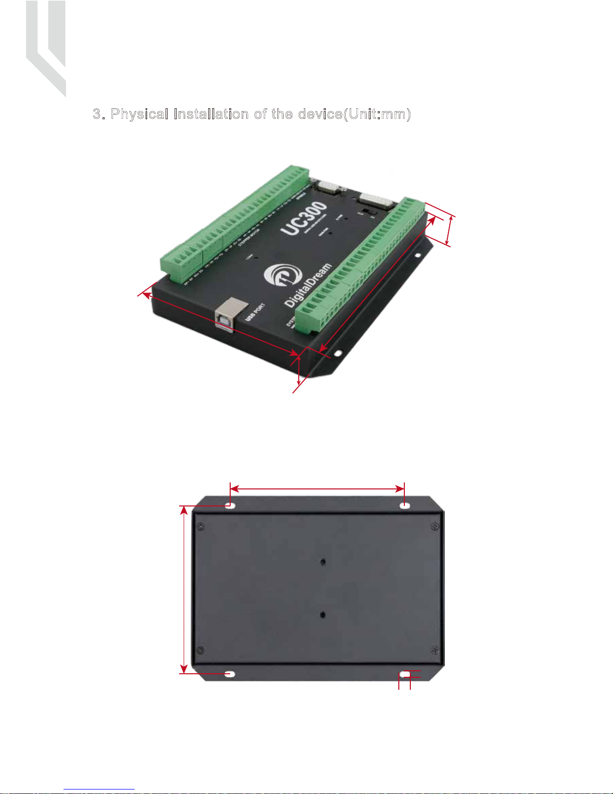
3. Physical Installation of the device(Unit:mm)
The UC300 motion controller is with the sealed shell structure,there are 4pcs mounting holes around the
controller.We can fix 4pcs 4mm diameter holes at the cabinet,and install the controller into the cabinet.
Picture 3-1 UC300 Front Appearance and size
Picture 3-2 UC300 Installation Dimensions
7 mm
4 mm
116 mm
119 mm
171 mm
32 mm
106 mm
21 mm
Page -2Digital Dream Mach3 Motion Controller

4. Controller UC300 Power supply Solution
Picture 4-1 UC300 Power supply structure
UC300 User’s ManualPage -3Digital Dream Mach3 Motion Controller
The power supply solution in the field of the Industrial automation is always very complicated, there is a
lot of the GND, now we descript the structure of the power structure as below:
The power structure as the Picture 4-1,Power supply input and USB port share common GND, stepper
control module,Input&Output module,Spindle control module and MPG Port share common GND, between the
two sector there is photoelectric isolation. Inside of the board, there is GND as common-.
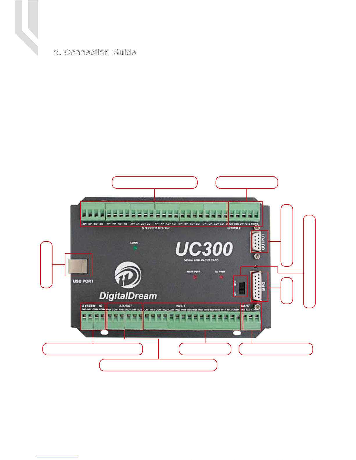
5. Connection Guide
The following drawing shows the main connections of our device.We will descrip one by one in next
pages.Here are:
1 : USB Communication Interface to PC
2 : Stepper/Servo motor Driver connection port
3 : Spindle Control Output Port
4 : Gerneral Output Interface
5 : MPG Port
6 : Functional Switch for MPG:Standard MPG or Digital Dream MPG
7 : Serial Extend Port
8 : Input Port:Limit/Home/Probe and so on
9 : Adjustable parameter Input Port
10 : Main System and IO Power Port
Picture 5-1 EC500 Wiring Over-view
10:System and IO Power Port
2: Stepper/Servo Driver
1: USB Port
5: MPG
8:Input Port
4: Genernal Output
6: Optionanl Swirtch for MPG
3: Spindle Control
7:Serial Extend Port
9:Adjustable parameter Input Port
UC300 User’s ManualPage -4Digital Dream Mach3 Motion Controller
5.1 USB Communication Port to PC
To setup the connection between the controller and the Mach3 software on computer,UC300 use the USB
port,as the Marked No.1 on Picture 5-1.
UC300 User’s ManualPage 5Digital Dream Mach3 Motion Controller
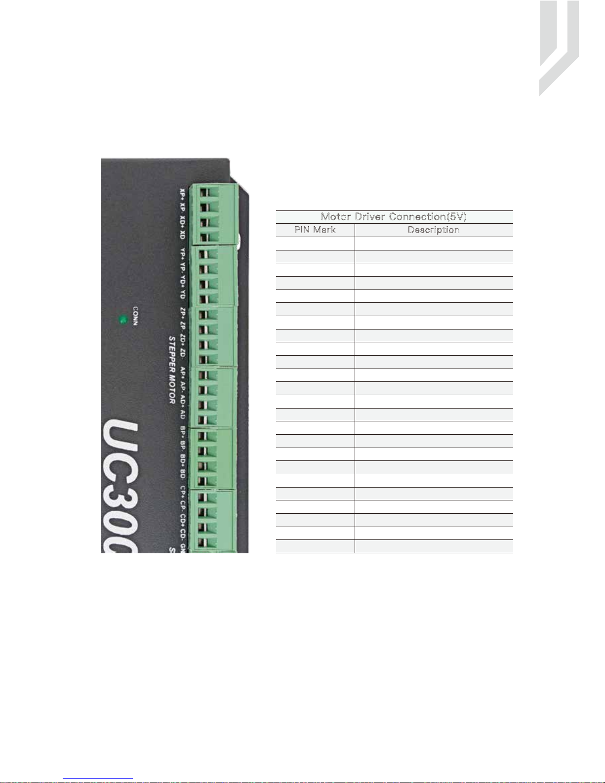
5.2 Stepper/Servo Motor Control Interface Connection
Picture 5-2 UC300 Stepper/Servo Mark and description
PIN Mark Description
XP+
XP-
XD+
XD-
YP+
YP-
YD+
YD-
ZP+
ZP-
ZD+
ZD-
X Axis Direction Output -
X Axis Direction Output +
X Axis Pulse Output -
X Axis Pulse Output +
Y Axis Direction Output -
Y Axis Direction Output +
Y Axis Pulse Output -
Y Axis Pulse Output +
Z Axis Direction Output -
Z Axis Direction Output +
Z Axis Pulse Output -
Z Axis Pulse Output +
AP+
AP-
AD+
AD- A Axis Direction Output -
A Axis Direction Output +
A Axis Pulse Output -
A Axis Pulse Output +
BP+
BP-
BD+
BD- X Axis Direction Output -
B Axis Direction Output +
B Axis Pulse Output -
B Axis Pulse Output +
CP+
CP-
CD+
CD-
Motor Driver Connection(5V)
B Axis Direction Output -
C Axis Direction Output +
C Axis Pulse Output -
C Axis Pulse Output +
C Axis Direction Output -
As the Marked No. 2 from Picture 5-2,there is the Stepper/Ser-
vo Interface.The device can be used to control machine tools
with stepper or servo motor controls with pulse and direction
signals.The option for users is 3-6 axis.
 Loading...