

Digital Dream DM500 User Manual
Handheld Motion Controller
For Engraving Machine
DM500
User’s Manual
The version of 20170806
1 DM500 Motion Controller Introduction
1) Max. 4 Axis;2-4 Axis linear interpolation,any 2 axis circular interpolation;
2) 7 opto isolated digital outputs,8 opto isolated digital inputs;
3) Support every Input and output port definition by users.
4) The controller need 2 power supply,one power supply is for system power,one is for input and output
ports power.Both input power is 24V,2A.
5) Open-collector output, Max. output current is 500mA,can power the relay directly;
6) Differential Pulse and direction output signal,Max. 500Khz per axis;
7) Spindle Control: 3 I/O ports control 8 different speeds(3 lines 8 speeds),1 I/O control the Start/Stop;
8) The System Support standard G-code.Also Support the popular CAD/CAM software,such as ArtCam,-
MasterCam,ProE and so on.
9) USB flash disk support for G code file input;
10) The control system can preview the process path before machining,and it makes the system more
steady,working smoothy and precise;
11) Acceleration/Deceleration Mode: S curve;
12) Support un-limited size file for machining;
13) Manual/Automatic machining function;
14) Support the operation to Start a G code from a specific line;
15) Support for “Power Cut” recovery. Data is automatically saved;
16) Support time-lock function;
17) Support 4 kinds operation rights:visitor,operator,admin,super admin;
Digital Dream has a 20 years history in the numerical control industry, specializing in the research, devel-
opment and production of various CNC (Computer Numerical Control) systems. DigitalDream aims to combine
high quality and high reliability with affordability. We produce 1 axis to 6 axes CNC system.
Thank you for choosing digital dream’s motion controllers.With a lots of examples and charts,this manual
will describe the features,functions and every operations of our controllers.Pls read this manual carefully before
any assembling and using.Incorrect handling can result in injury and damage to persons and engraving
machine.Pls keep the manual carefully for convenient to read it at any time in need.
DM500 is very professional 4 Axis CNC Motion Controller which is based on embedded system.DM500
operates as a standalone system without the need of a computer,and with a pendant,it makes users very conve-
nient to opreate the machines.Our controller adopts Embedded Operating System,by which the controller will
never get virus-infected.And the controller adopts look-ahead algorithm by which the the controller can read
more ahead 30-lines G-code than the operating.All the features guarantees high precision,accuracy and reliabili-
ty.And the size is very small,oepreation is very easy,very suitable for all size of Engraving machines,Milling
machines and cutting machines and so on.
1.1 Introduction of Product
1.2 Performance parameter of the DM500
Page -1 DM500 User’s Manual
The DM500 motion controller contains the handheld motion controller,circuit switching wiring board,and
HDMI digital high-definition transmission cable.
The handheld motion controller and wiring board are communicated by 2 Meter 37 pins HDMI digital
high-definition transmission cable which is shielding twisted-pair cable to avoid interference.
The wiring board can be installed by DIN linearguide ways No. C45.
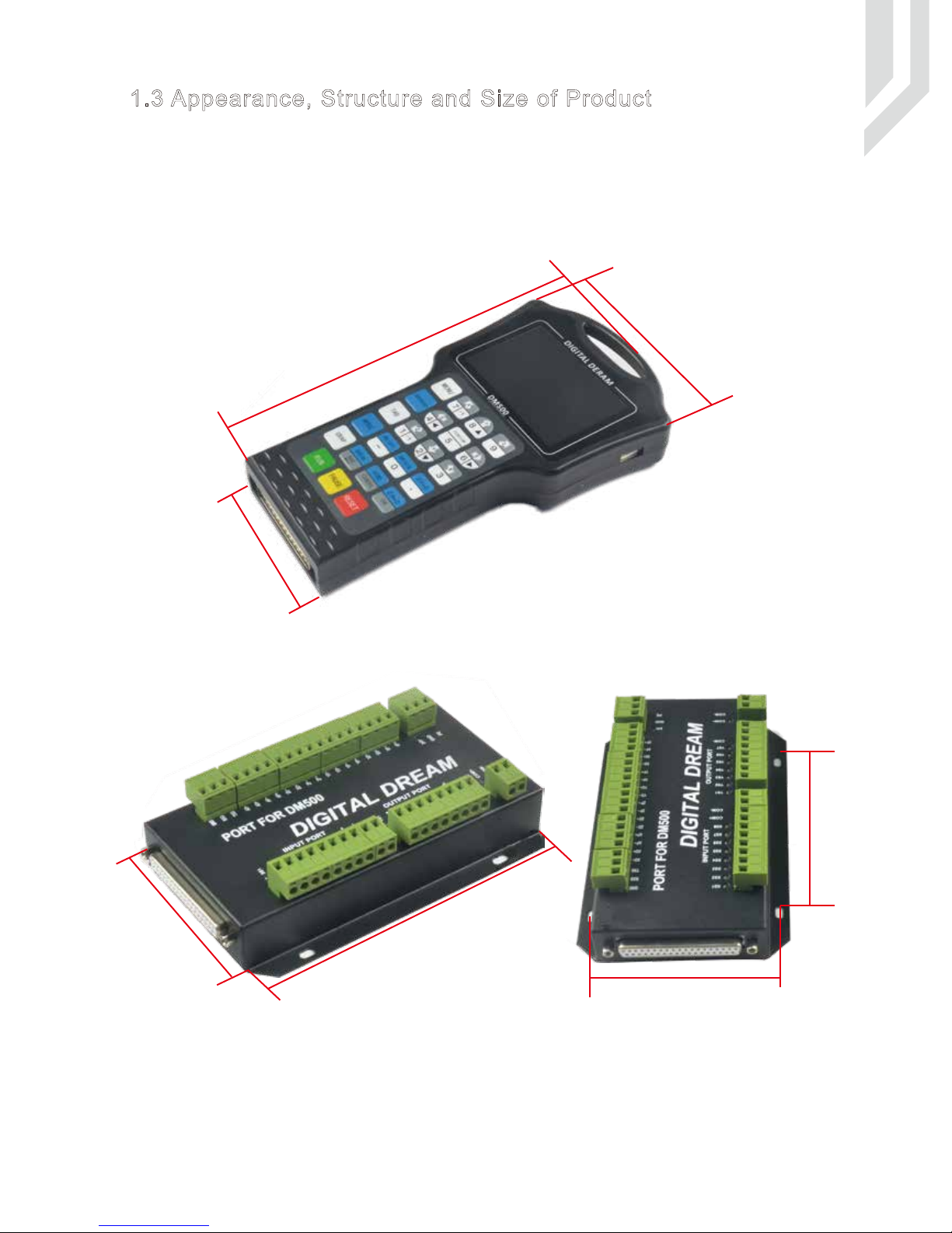
1.3 Appearance, Structure and Size of Product
Picture 1-1 DM500 Pendant Size
Page -2 DM500 User’s Manual
93 mm
230 mm
116 mm
The wiring board
Size
72 mm
118 mm
100 mm
88 mm
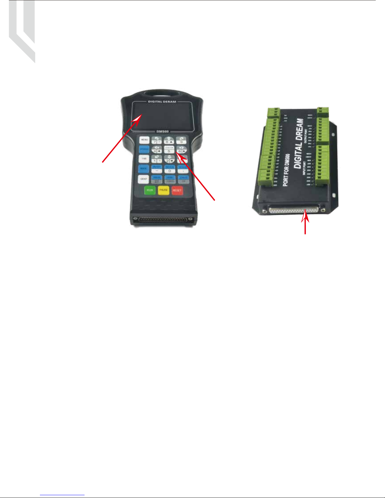
The front panel consists of 23 user keys and the 3.5’’ (480*320 ) LCD.
DM500 User’s ManualPage -3
3.5'' Screen
23 user’s keys
37 pins Male Interface 37 pins Female Interface
When operating the DM500 Controller, the users will come across some English abbreviations. Here a list
with explanations
FRO: Feed Rate Override
SRO: Spindle Rate Override
SRJ: Jog Speed Setting
F: Feed rate, unit is mm/min
S: Spindle Speed, unit rev/min.
X: The coordinate code of the X axis.
Y: The coordinate code of the Y axis.
Z: The coordinate code of the Z axis.
A: The coordinate code of the A axis
BUSY: The system is busy. You still can adjust FRO and SRO
READY: READY mode, any operation can be done
RESET: Reset mode, controller is in “OFF” mode, no operation can be performed
CONT: Continuous mode, each axis can be manually jogged with the arrow keys
Step :Manual Step Mode,each axis can be jogged in defined steps
MPG: MPG mode. Operate the machine with the MPG (Manual Pulse Generator)
AUTO: Run G code. Auto is showing when file is processing
Keep away from exposure to moisture or water. This product contains sophisticated electronics
and must not get wet.
Wiring warning: the IO input terminal of this controller supports equipment with source power (such as
Inductive Proximity Switch ). When using this kind of equipment, pay attention to the polarity. Avoid the
+terminal to be connect with GND. This controllers has analog output for spindle control (0-10V). Please avoid
this terminal to ever connect with GND as damage to the controller may occur.
Operation warning. Please observe all security measures when operating the machine. The ESTOP
must be connected and properly labelled. In case of a problem, press the E-stop at once to avoid
damage to humans, animals and the equipment.
High voltage danger. The DM500 is connected to18-32V DC. Obey and follow the electricity safety
rules of your country when connecting this equipment.
1.4 Explanation of Abbreviations
1.5 Notes and Warnings
DM500 User’s ManualPage -4
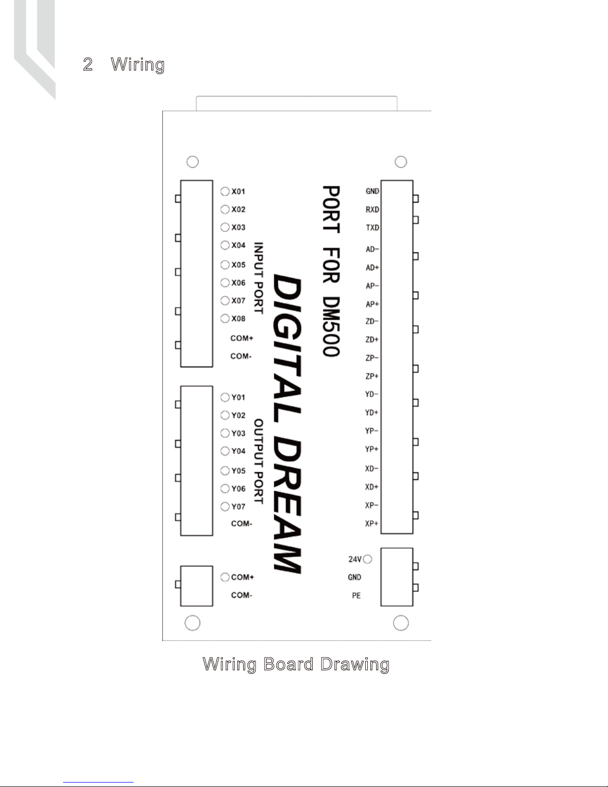
2 Wiring
Wiring Board Drawing
Page -5
Notice:
1. The users should prepare two power supply switch for each controller.One is for the controller
system,one is for the Inputs and Output ports.
2. 24V GND is the power supply for the controller,COM+ and COM- is the common terminal for Input
and Output ports.
3. The Low voltage for input signal is effective.By default it is the NPN switch.
4. The pulse and direction signal is differential output.
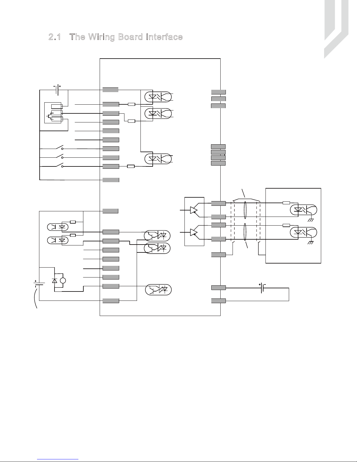
2.1 The Wiring Board Interface
DM500 User’s ManualPage -6
Port Board for DM500
COM-
COM+
5.1K
X01
5.1K
X02
5.1K
X08
X03
X04
X05
X06
X07
.
.
.
.
.
.
X Axis Home
Y Axis Home
Z Axis Home
A Axis Home
(Pause)
(Start)
Extended Input Port 1
Extended Input Port 2
Extended Input Port 3
(E-stop)
Probe
DC24V
Power supply For Inputs and Outputs
COM-
Y01
Y02
Y03
Y04
Y05
Y06
Y07
.
.
.
.
.
.
DC24V
RY
Spindle
Start/stop
M3/M5
Line 1
Line 2
Line 3
Error Output
Cooling M8/M9
Lubrication M10/M11
External Power Supply
BN
BK
BU
Mechanical swhtch
Proximity switch
COM+
Pulse+
Shieding Twist Cable
XP-
XD+
XD-
XP+
PE
Pulse-
Direction+
Direction-
Driver
DC24V
GND
RXD
TXD
RS232
communication
port
24V
GND
DS26LS31
APAD+
AD-
AP+
YZA Axis Signal Output Ports
(the connections same as the X Axis as below shows)
.
.
.
.
.
.
Power Supply For Contoller
The Max. capacity of the output
ports is 30V,500mA.
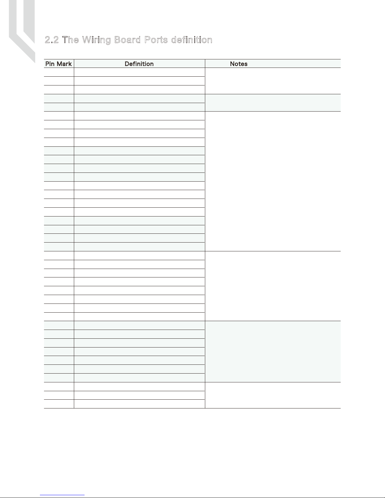
2.2 The Wiring Board Ports definition
Power supply 24VDC positive side for System power
Power supply 24VDC negative side for system power
SHELL GROUND
Power supply 24VDC positive side for Inputs and Output Ports.
Power supply 24VDC negative side for Inputs and Output Ports.
X Axis Pulse signal output +
X Axis Pulse signal output -
X Axis Direction signal output+
X Axis Direction signal output -
Y Axis Pulse signal output +
Y Axis Pulse signal output -
Y Axis Direction signal output+
Y Axis Direction signal output -
Z Axis Pulse signal output +
Z Axis Pulse signal output -
Z Axis Direction signal output+
Z Axis Direction signal output -
A Axis Pulse signal output +
A Axis Pulse signal output -
A Axis Direction signal output+
A Axis Direction signal output -
X Axis Limit/Home Signal Input Port
Y Axis Limit/Home Signal Input Port
Z Axis Limit/Home Signal Input Port
A Axis Limit/Home Signal Input Port
Probe Signal Input Port
Extended Input Port 1,can be configured as E-STOP
Extended Input Port 2,can be configured as Start or Probe
Extended Input Port 3,can be configured as Pause
Spindle Start/Stop Output Port
Spindle Speed Setting 1 Output Port
Spindle Speed Setting 2 Output Port
Spindle Speed Setting 3 Output Port
Alarm Output
Cooling output Port (M8/M9)
Lubrication output Port (M10/M11)
Receive Port of communication
Send Port of Communication
Ground of Communication Port
The Power Supply is for controller system.DC24V,3A.
The Power Supply is for Input and Output Ports.DC24V,3A.
These Outputs is for Servo Driver/Stepper Driver.
Max. output 500Khz for each axis.
RS232
These Output ports for the controls of Spindle.
Y02/Y03/Y03 are for settings of spindle 8 different speeds.
Open-collector output,installed,Current:500mA,Voltage:30V
These all Input Ports.
Support mechanical/Opto/Proximity Limited Switch
Limited Switch Power:24V
Mode: NPN
Effective Voltage:0V
24V
PE
COM+
COM-
XP+
XP-
XD+
XD-
YP+
YP-
YD+
YD-
ZP+
ZP-
ZD+
ZD-
AP+
AP-
AD+
AD-
X01
X02
X03
X04
X05
X06
X07
X08
Y01
Y02
Y03
Y04
Y05
Y06
Y07
RXD
TXD
GND
GND
Pin Mark Definition Notes
DM500 User’s ManualPage -7

DM500 User’s ManualPage -8
2.3 The Wiring Board Ports Description
2.3.1 The Power Supply Wiring
In general, the power supply of industrial control’s equipment products are complex. They have many
different ground levels. The internal power structure of this product is as follows:
It’s recommended to add a filter to prevent the electric interference.
The power for input/output ports is 24VDC,the power for Main controller system is also 24VDC.Because
inside of the controller system,the power design for input/output ports and main controller already isolated,its
recommended to give them two independent power supply.
Main controller use the same power supply with Input/output ports.(no recommended).
GND
PE
24V
COM-
COM+
DB37
Filter
Switch Power
Suply 2
L N
+24V
GND
PE
PE
PE
Filter
Switch Power
Supply 1
L N
+24V
GND
PE
PE
GND
PE
24V
COM-
COM+
DB37
Filter
Switch Power
Supply
L N
+24V
GND
PE
PE
PE
DM500 User’s ManualPage -9
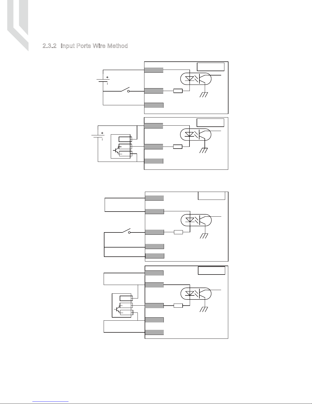
2.3.2 Input Ports Wire Method
When the Inputs and Output Ports (COM+ COM-) use the independent Power supply:
When the Inputs and Output Ports (COM+ COM-) share the same Power supply with the controller:
It’s the best to use the first independent power supply method.Logic low Effective.NPN normal open
proximity switch.
DC24V
Motion
Controller
Motion
Controller
Motion
Controller
Xxx
COM+
COM-
Motion
Controller
DC24V
Xxx
COM+
COM-
Proximity Switch
NPN Normal Open Mode
BN
BK
BU
Xxx
COM+
COM-
Xxx
COM+
COM-
BN
BK
BU
24V
GND
24V
GND
Proximity Switch
NPN
Normal Open Mode
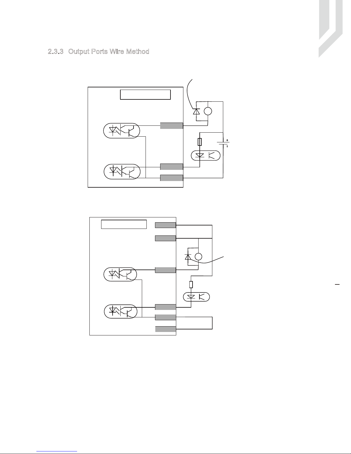
2.3.3 Output Ports Wire Method
0.00.20.40.60.81.0
DM500 User’s ManualPage -10
When the Inputs and Output Ports (COM+ COM-) use the independent Power supply:(Recommended)
When the Inputs and Output Ports (COM+ COM-) share the same Power supply with the controller:
There is 7 output pins,the electric circuit just as the above file showing.
When you connect the relay,pls install a fly-wheel diode as the drawing showing.
The first Independent power supply method is recommended.
DC 24V
RY
Motion
Controller
Yxx
Yxx
COM-
The Max. capacity of the
output ports is 30V,500mA
The Max. capacity of the
output ports is 30V,500mA
If you connect a Relay here
it’s best to add a Diode
If you connect a Relay here
it’s best to add a Diode
RY
Motion
Controller
Yxx
Yxx
COM-
COM+
24V
GND
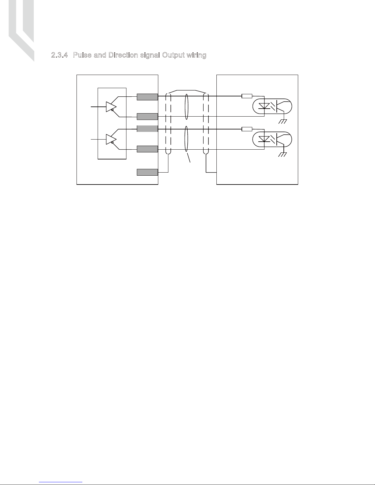
2.3.4 Pulse and Direction signal Output wiring
DM500 User’s ManualPage -11
Take X axis for example:
Y,Z,A axis wiring are same as X axis;
The controller use differencial output methods,And The Max. Output Frequency is 500Khz;
Cannot connect as Common anode and cathode;
Pulse+
Twist
Shielding
Cable
Pls use twist Shielding
cable for the connection
XP-
XD+
XD-
XP+
PE
Pulse-
Direction+
Direction-
Servo/Stepper
Driver
DS26LS31
Motion
Controller
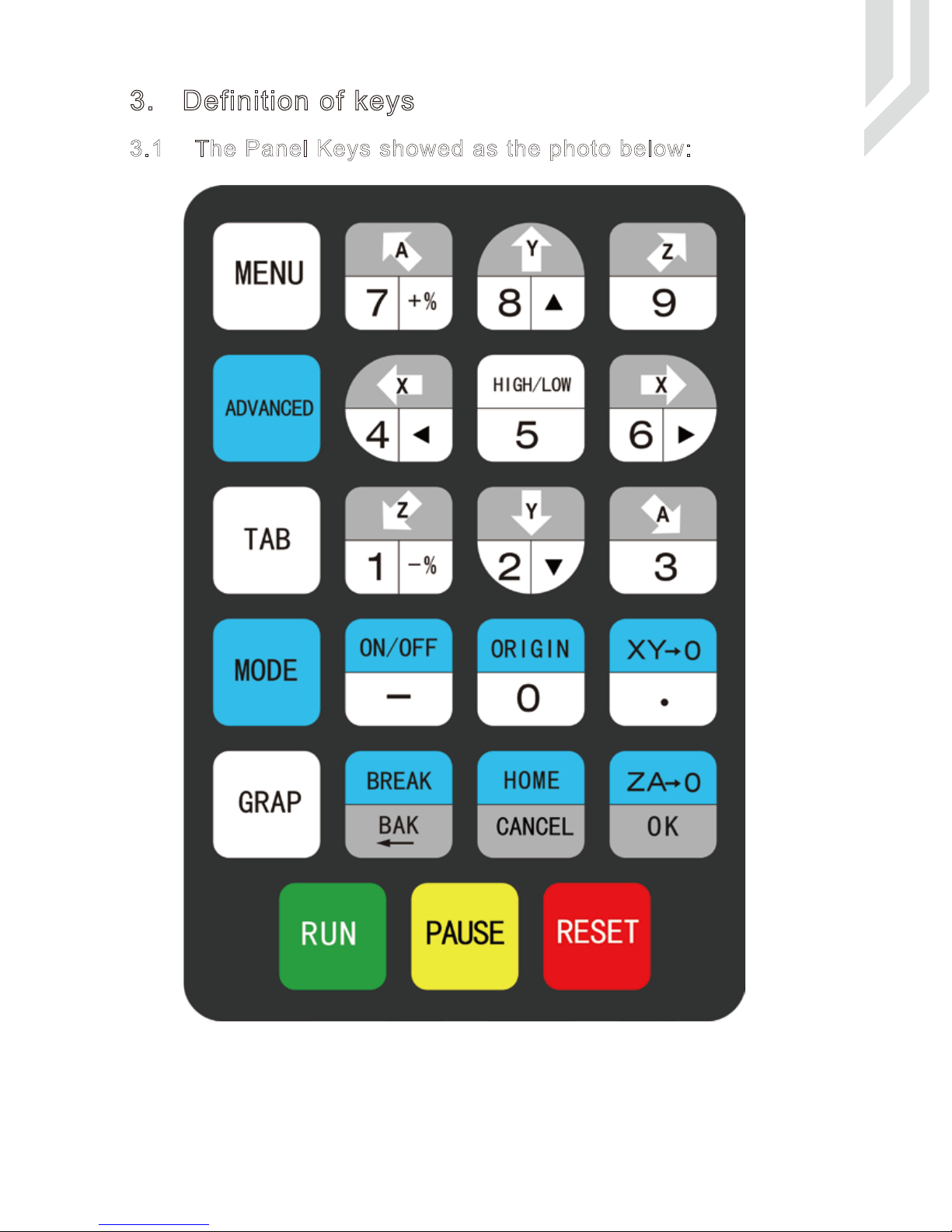
3. Definition of keys
+
DM500 User’s ManualPage -12
3.1 The Panel Keys showed as the photo below:
 Loading...