

Page 1

DIGITAL
CONTROL
INCORPORATED
www.DigiTrak.com
™
Directional Drilling Locating System
Operator’s Manual
Page 2

403-1000-00-C1, Aug 2013
Copyright © 2005-2013 by Digital Control Incorporated. All rights reserved.
DIGITAL CONTROL INCORPORATED
Trademarks
The DCI logo, CableLink®, DataLog®, DigiTrak®, Eclipse®, F2®, F5®, iGPS®, MFD®, SST®, target-in-thebox®, Target Steering®, and TensiTrak
F Series™, FSD™, FasTrak™, LWD™, SBP™, SE™, SED™, SuperCell™, and TeleLock™ are
trademarks of Digital Control Incorporated.
®
are U.S. registered trademarks and DucTrak™, FBC™, FBP™,
Limited Warranty
All products manufactured and sold by Digital Control Incorporated (DCI) are subject to the terms of a
Limited Warranty. A copy of the Limited Warranty is included at the end of this manual; it can also be
obtained by contacting DCI Customer Service, 425-251-0559 or 800-288-3610, or at DCI's website,
www.digitrak.com.
Important Notice
All statements, technical information, and recommendations related to the products of DCI are based on
information believed to be reliable, but the accuracy or completeness thereof is not warranted. Before
utilizing any DCI product, the user should determine the suitability of the product for its intended use. All
statements herein refer to DCI products as delivered by DCI and do not apply to any user customizations
not authorized by DCI nor to any third-party products. Nothing herein shall constitute any warranty by DCI
nor will anything herein be deemed to modify the terms of DCI’s existing Limited Warranty applicable to all
DCI products. The most recent version of this manual is available on DCI's website.
Compliance Statement
This equipment complies with Part 15 of the Rules of the FCC and with Industry Canada license-exempt
RSS standards and with Australia Class License 2000 for LIPD (low interference potential devices).
Operation is subject to the following two conditions: (1) this equipment may not cause harmful
interference, and (2) this equipment must accept any interference received, including interference that
may cause undesired operation. DCI is responsible for FCC compliance in the United States: Digital
Control Incorporated, 19625 62nd Ave S, Suite B103, Kent WA 98032; phone 425-251-0559 or 800-288-
3610.
Changes or modifications to any DCI equipment not expressly approved and carried out by DCI will void
the user’s Limited Warranty and the FCC’s authorization to operate the equipment.
CE Requirements
DigiTrak receivers are classified as Class 2 radio equipment per the R&TTE Directive and
may not be legal to operate or require a user license to operate in some countries. The list of restrictions
and the required declarations of conformity are available on DCI’s website, www.digitrak.com, under the
Service & Support tab. Click on DOWNLOADS and select from the CE Documents pull-down menu to
download, view, or print the documents.
2 DigiTrak®
L
Operator’s Manual
T
™
Page 3

DIGITAL CONTROL INCORPORATED
United States
DCI Headquarters
19625 62nd Ave S, Suite B103
Kent, Washington 98032, USA
+1.425.251.0559 / 1.800.288.3610
+1.425.251.0702 fax
Australia
2/9 Frinton Street
Southport QLD 4215
+61.7.5531.4283
+61.7.5531.2617 fax
China
368 Xingle Road
Huacao Town
Minhang District
Shanghai 201107, P.R.C.
+86.21.6432.5186
+86.21.6432.5187 fax
Europe
Brueckenstraße 2
97828 Marktheidenfeld
Germany
+49.9391.810.6100
+49.9391.810.6109 fax
India
DTJ 1023, 10th Floor
DLF Tower A, DA District Center
Jasola, New Delhi 110044
+91.11.4507.0444
+91.11.4507.0440 fax
Russia
Molodogvardeyskaya Street, 4
Building 1, Office 5
Moscow, Russia 121467
+7.499.281.8177
+7.499.281.8166 fax
Contact Us
DigiTrak®
L
Operator’s Manual 3
T
™
Page 4

DIGITAL CONTROL INCORPORATED
Dear Customer,
Thank you for choosing a DigiTrak locating system. We are extremely proud of the equipment we have
been designing and building in Washington State since 1990. We believe in providing a unique, highquality product and standing behind it with superior customer service and training.
Please take the time to read this entire manual, especially the section on safety. Also, please fill in the
product registration card provided with this equipment and either mail it to DCI headquarters, fax it to us
at 253-395-2800, or complete and submit the form online at our website, www.digitrak.com. We will put
you on the Digital Control mailing list and send you product upgrade information and our FasTrak
newsletter.
Feel free to contact us if you have any problems or questions. Our Customer Service department is
available 24 hours a day, 7 days a week. International contact information is available on our website.
As the horizontal directional drilling industry grows, we’re keeping our eye on the future to develop
equipment that will make your job faster and easier. Visit us online any time to see what we’re up to.
We welcome your questions, comments, and ideas.
Digital Control Incorporated
Kent, Washington
2013
See our DigiTrak Training Videos on YouTube at www.youtube.com/dcikent.
4 DigiTrak®
L
Operator’s Manual
T
™
Page 5

DIGITAL CONTROL INCORPORATED
Table of Contents
Safety Precautions and Warnings ................................................................................................................. 7
General .................................................................................................................................................... 7
Equipment and Battery Disposal ............................................................................................................. 8
Pre-Drilling Testing .................................................................................................................................. 8
Interference .............................................................................................................................................. 8
Equipment Maintenance .......................................................................................................................... 9
Introduction.................................................................................................................................................. 10
Power Requirements ............................................................................................................................. 11
Environmental Requirements ................................................................................................................ 11
Receiver ...................................................................................................................................................... 12
Main Display Screen .............................................................................................................................. 13
Standard Display Screen Symbols ........................................................................................................ 14
Power On/Off ......................................................................................................................................... 15
Proper Handling of Receiver .................................................................................................................. 15
Accessing and Changing Menu Settings ............................................................................................... 16
Receiver Display Menus ........................................................................................................................ 16
Transmitter .................................................................................................................................................. 26
Types of LT Transmitters ....................................................................................................................... 26
Transmitter Housing Requirements ....................................................................................................... 27
Transmitter Battery Power ..................................................................................................................... 28
Transmitter Temperature ....................................................................................................................... 28
Sleep Mode (Automatic Shutoff) ............................................................................................................ 29
General Transmitter Care Instructions ................................................................................................... 29
Remote Display ........................................................................................................................................... 30
Main Display Screen .............................................................................................................................. 30
Remote Display Menus .......................................................................................................................... 32
Power On/Off .................................................................................................................................... 32
Telemetry Channel Settings ............................................................................................................. 32
Backlight On/Off ................................................................................................................................ 32
Depth Units ....................................................................................................................................... 33
Pitch Units ......................................................................................................................................... 33
Battery Charger ........................................................................................................................................... 34
General Description ............................................................................................................................... 34
AC/DC Power Setup .............................................................................................................................. 35
Charging a Battery ................................................................................................................................. 35
Locating Instructions ................................................................................................................................... 38
Depth or Slant Distance ......................................................................................................................... 38
Locate Points (FLP & RLP) and Locate Line (LL) ................................................................................. 38
Effects of Depth, Pitch, and Topography on Distance Between FLP and RLP .................................... 39
Marking Locate Points ........................................................................................................................... 40
Locating the Transmitter – Standard Method ........................................................................................ 41
Finding the FLP ................................................................................................................................ 42
Finding the Transmitter and the LL ................................................................................................... 43
Confirmation of Exact Heading and Transmitter Position ................................................................. 44
Finding the RLP ................................................................................................................................ 45
Plus/Minus ("+/–") Locating Method ....................................................................................................... 46
Finding the FLP ................................................................................................................................ 46
Finding the Transmitter and the LL ................................................................................................... 47
DigiTrak®
L
Operator’s Manual 5
T
™
Page 6

Confirmation of Exact Heading and Transmitter Position ................................................................. 48
Finding the RLP ................................................................................................................................ 48
Limited Warranty
DIGITAL CONTROL INCORPORATED
6 DigiTrak®
L
Operator’s Manual
T
™
Page 7
DIGITAL CONTROL INCORPORATED
Warning All operators must read and understand the following safety
precautions and warnings and must review this operator’s manual
before using the DigiTrak F5 Locating System.
Serious injury and death can result if underground drilling equipment makes
contact with an underground utility such as a high-voltage electrical cable or a
natural gas line.
Substantial property damage and liability can result if underground drilling
equipment makes contact with an underground utility such as a telephone, cable
TV, fiber-optic, water, or sewer line.
Work slowdowns and cost overruns can occur if drilling operators do not use the
drilling or locating equipment correctly to obtain proper performance.
DCI equipment is not explosion-proof and should never be used near flammable
or explosive substances.
In the event of electrostatic shock, the display screen may go blank. No data loss
will occur. Click the trigger to reset the receiver, or toggle down to reset the
remote display.
Hot surfaces can occur on cable transmitters if housing requirements are not met.
Always ensure the transmitter is installed properly in the housing during use.
Safety Precautions and Warnings
Carefully review this manual and be sure you always operate your DigiTrak locating system properly to
obtain accurate depth, pitch, roll, and locate points. If you have any questions about the operation of the
system, please contact DCI Customer Service for assistance.
General
Directional drilling operators MUST at all times:
Understand the safe and proper operation of drilling and locating equipment, including the use of
ground mats and proper grounding procedures.
Ensure that all underground utilities have been located, exposed, and accurately marked prior to
drilling.
Wear protective safety clothing such as dielectric boots, gloves, hard hats, high-visibility vests, and
safety glasses.
Locate and track the transmitter in the drill head accurately and correctly during drilling.
Maintain a minimum distance of 8 in. (20 cm) from the front of the receiver to the user’s torso to
ensure compliance with FCC requirements.
Comply with federal, state, and local governmental regulations (such as OSHA).
Follow all other safety procedures.
DigiTrak®
L
Operator’s Manual 7
T
™
Page 8

This symbol on equipment indicates that the equipment must not be disposed of with your
other household waste. Instead, it is your responsibility to dispose of such equipment at a
designated collection point for the recycling of batteries or electrical and electronic
equipment. If the equipment contains a banned substance, the label will show the pollutant
(Cd = Cadmium; Hg = Mercury; Pb = Lead) near this symbol. Before recycling, ensure
batteries are discharged or the terminals are covered with adhesive tape to prevent
shorting. The separate collection and recycling of your waste equipment at the time of
disposal will help conserve natural resources and ensure it is recycled in a manner that
protects human health and the environment. For more information about where you can
drop off your waste equipment for recycling, please contact your local city office, your
household waste disposal service, or the shop where you purchased the equipment.
DigiTrak locating systems cannot be used to locate utilities.
Continued exposure of the transmitter to heat due to frictional heating of the drill head can cause
inaccurate information to be displayed and may permanently damage the transmitter.
Remove the batteries from all system components during shipping and prolonged storage; damage
caused by leakage may occur.
DIGITAL CONTROL INCORPORATED
Equipment and Battery Disposal
The battery charger provided with your DigiTrak locating system is designed with adequate safeguards to
protect you from shock and other hazards when used as specified within this document. If you use the
battery charger in a manner not specified by this document, the protection provided may be impaired. Do
not attempt to disassemble the battery charger, it contains no user-serviceable parts. The battery charger
shall not be installed into caravans, recreational vehicles, or similar vehicles.
Pre-Drilling Testing
Before each drilling run, test your DigiTrak locating system with the transmitter inside the drill head to
confirm it is operating properly and providing accurate drill head location and heading information.
During drilling, the depth will not be accurate unless:
The receiver has been properly calibrated and the calibration has been checked for accuracy so the
receiver shows the correct depth.
The transmitter has been located correctly and accurately and the receiver is directly above the
transmitter in the drill head underground or at the front locate point.
The receiver is placed on the ground or held at the correct height-above-ground distance, which has
been set correctly.
Always test calibration after you have stopped drilling for any length of time.
Interference
Interference can cause inaccuracies in the measurement of depth and loss of the transmitter’s pitch, roll,
or heading. Always perform a background noise check prior to drilling.
Sources of interference include, but are not limited to, traffic signal loops, invisible dog fences, cable
TV, power lines, fiber-trace lines, metal structures, cathodic protection, telephone lines, cell phones,
transmission towers, conductive earth, salt, salt water, rebar, and radio frequencies.
8 DigiTrak®
L
Operator’s Manual
T
™
Page 9

DIGITAL CONTROL INCORPORATED
Interference at the remote display may also occur from other sources operating nearby on the same
frequency, such as car rental agencies using their remote check-in modules or other directional
drilling locating equipment.
Background noise must be minimal and signal strength must be at least 150 points above the
background noise during all locating operations.
Because this equipment may generate, use, and radiate radio frequency energy, there is no
guarantee that interference will not occur at a particular location. If this equipment does interfere with
radio or television reception, which can be determined by powering the equipment off and on, try to
correct the interference using one or more of the following measures:
o Reorient or relocate the receiving antenna.
o Increase the separation between the receiver and affected equipment.
o Consult the dealer, DCI, or an experienced radio/TV technician for help.
o Connect the DCI equipment to an outlet on a different circuit.
Equipment Maintenance
Turn off all equipment when not in use.
Store the equipment in cases, away from heat, cold, and moisture. Test to confirm proper operation prior
to use.
Clean the screens on the receiver and remote display using a damp soft cloth without chemicals or
cleaning agents.
Clean the receiver, remote, and battery charger case using only a soft moist cloth and mild detergent.
Do not use chemicals to clean the transmitter.
Inspect the equipment daily and contact DCI if you see any damage or problems. Do not disassemble or
attempt to repair the equipment.
Do not store or ship this equipment with batteries inside. Always remove the batteries from the equipment
before shipping or periods of non-use.
DigiTrak®
L
Operator’s Manual 9
T
™
Page 10
DIGITAL CONTROL INCORPORATED
Remote
Display
Battery
Charger
Receiver
LX
Transmitter
Rechargeable
Battery Packs
Mini
Adapter
LS Transmitter
Introduction
DigiTrak LT Locating System
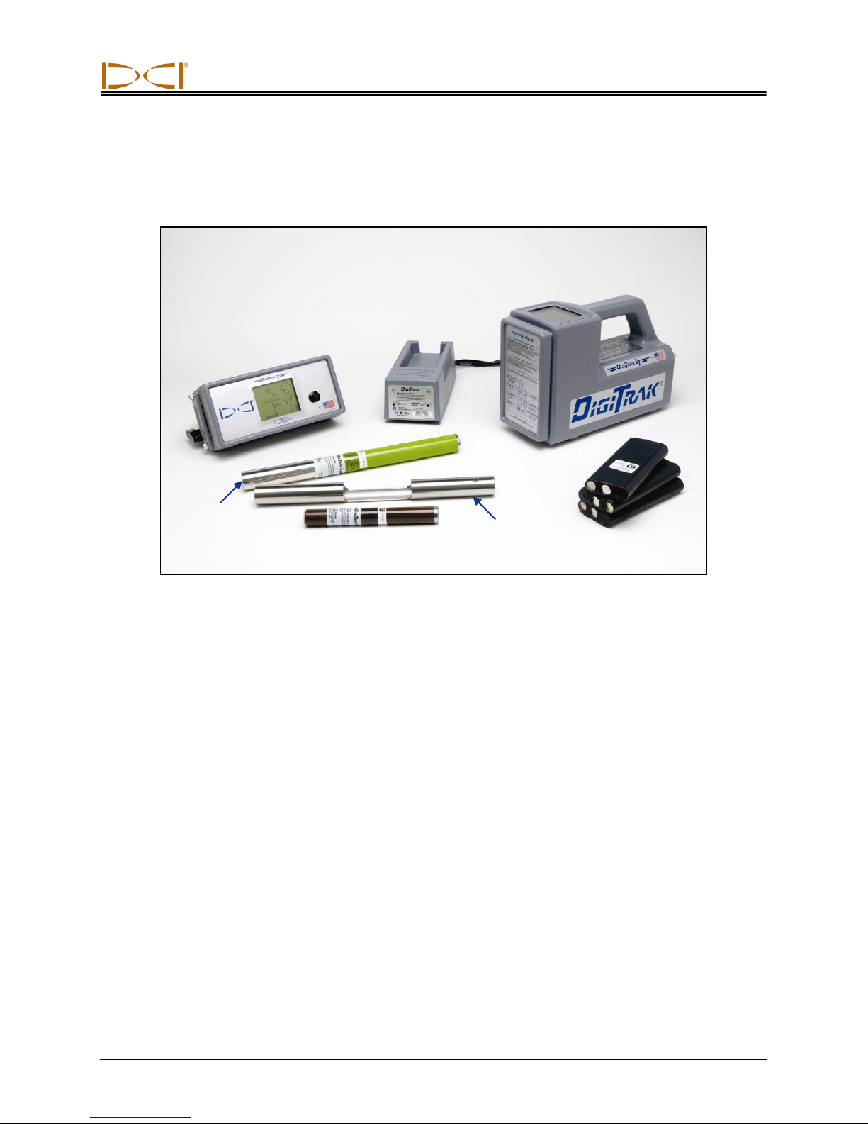
The DigiTrak LT Locating System is used to locate and track the drill head during horizontal directional
drilling (HDD) operations. The system consists of a handheld receiver, a transmitter, which is placed in
the drill head, and a remote display. The receiver and remote are powered by a rechargeable DCI battery
pack, and a battery charger is also included with the system.
Locating is streamlined using the LT receiver’s graphic display and menu system. The real-time graphic
display guides you in positioning a target (or a line) in a box on the display window to locate the transmitter in the drill head. You can also locate using the plus/minus signs, as on earlier DigiTrak models
produced by Digital Control Incorporated (DCI).
This manual provides information on each LT system component—the receiver, transmitter, remote display, and battery charger—in separate sections following this introduction. These sections are followed by
the Locating Instructions section, which explains important locating terms and gives step-by-step locating
instructions.
The remainder of this section presents the LT system’s power requirements, environmental requirements,
and equipment maintenance requirements.
If you have any questions about the information in this manual or about the use of the LT system, please
call DCI’s Customer Service Department at 800-288-3610 or 425-251-0559.
DigiTrak®
L
Operator’s Manual 10
T
™
Page 11
DIGITAL CONTROL INCORPORATED
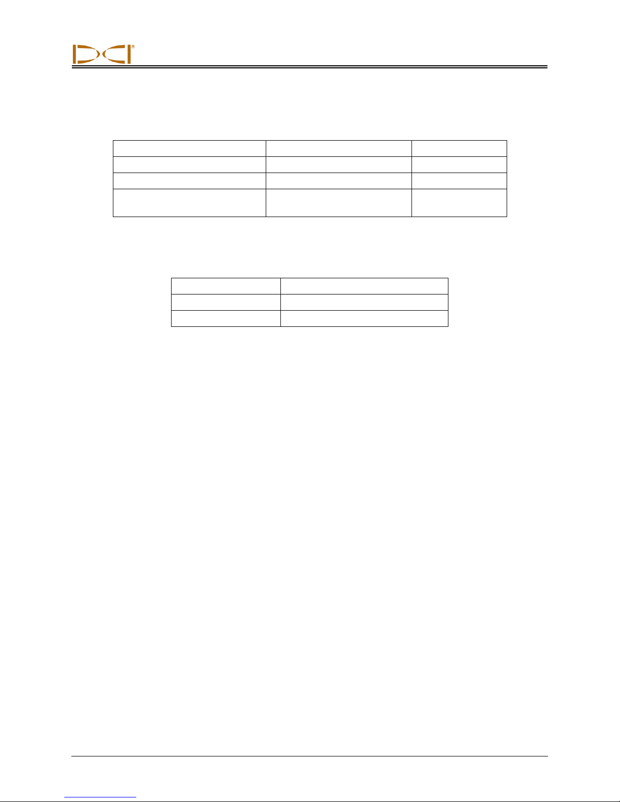
Device
Voltage
Current
DigiTrak LT Receiver
14.4 V DC (nominal)
< 0.25 A DC
DigiTrak LT Remote Display
14.4 V DC (nominal)
< 0.25 A DC
DigiTrak LT Battery Charger
12–28 V DC
100–240 V AC, 50/60 Hz
< 2.0 A DC
Altitude
Up to 6561 ft. (2000 m)
Temperature
-4°F to 140°F (-20°C to 60°C)
Relative Humidity
< 90%
Power Requirements
Environmental Requirements
DigiTrak®
L
Operator’s Manual 11
T
™
Page 12
DIGITAL CONTROL INCORPORATED
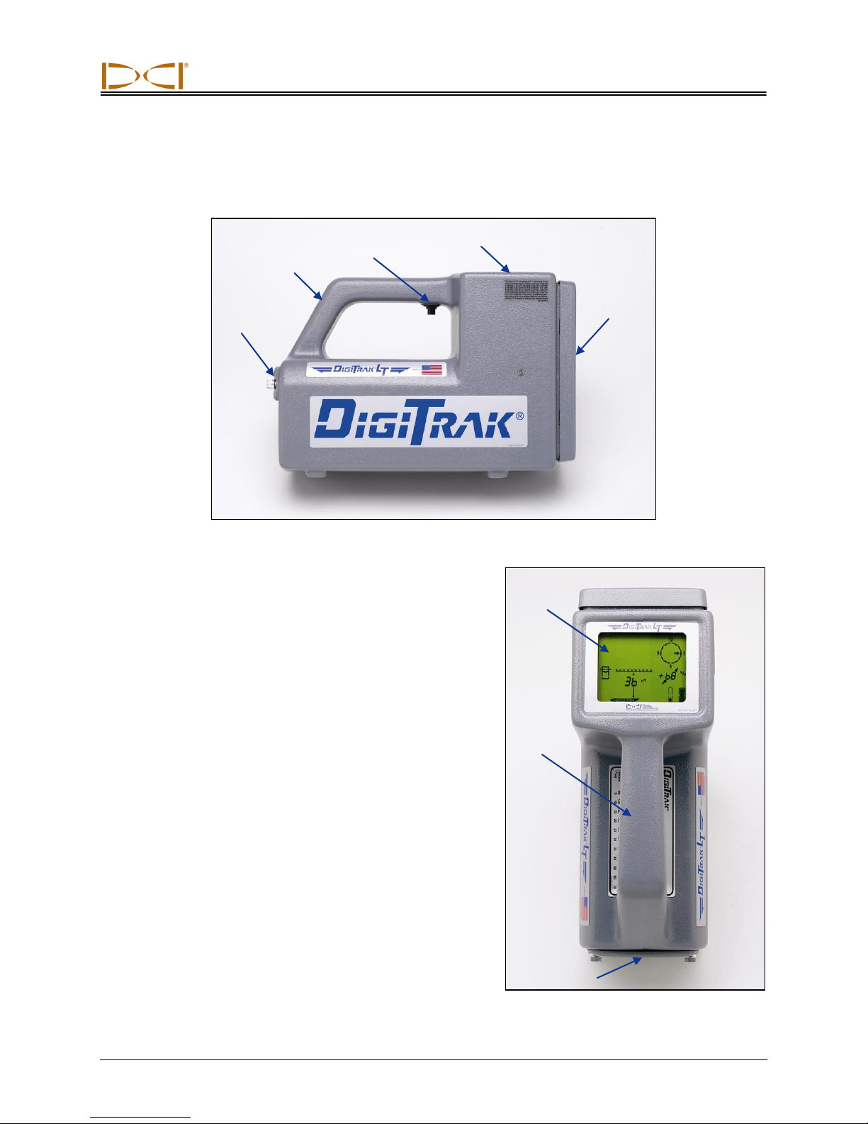
Handle
Trigger
Display Screen
Front
Panel
Battery
Compartment
DigiTrak LT Receiver (top view)
Display
Screen
Handle
Battery
Compartment
Receiver
DigiTrak LT Receiver (side view)
The LT receiver is a hand-held unit used for locating
and tracking an LT transmitter emitting a signal at
12 kHz. The receiver converts signals from the
transmitter and displays the following information:
depth, pitch, roll, and temperature of the transmitter,
and battery status of both the transmitter and the
receiver. The LT receiver also sends signals to the LT
remote display at the drill rig.
The LT system can be used to take depth readings
without setting the receiver on the ground. The heightabove-ground function allows you to program a
comfortable height for holding the receiver for depth
readings (see discussion under “Receiver Display
Menus” later in this section). Using the height-above-
ground feature also allows greater separation, which
can decrease the effects of interference.
DigiTrak®
L
Operator’s Manual 12
T
™
Page 13
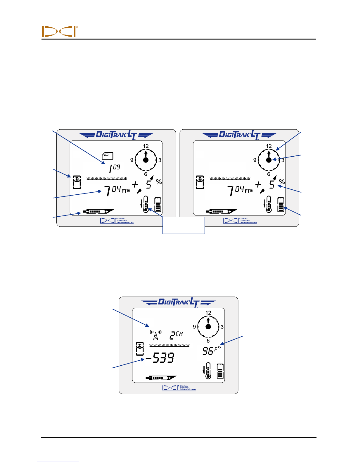
Receiver
Signal Strength (with
+/– Locating Symbol)
Replaces Distance to
Transmitter
Transmitter
Temperature
Replaces Pitch
Reading
Height-
AboveGround
Setting
Target-in-
the-Box®
Locating
Display
Distance to
Transmitter
Transmitter
Battery
Transmitter
Temperature
Transmitter
Roll (Clock)
Pitch/Roll
Update
Indicator
Transmitter
Pitch
Receiver
Battery
Telemetry Channel
Setting Replaces
Height-Above-
Ground Setting
Main Display Screen
When the LT receiver is on, the display screen usually shows the standard locating mode display (see
figure below), which is the default display. The display symbols that appear on the locating screen are
identified in the figure below and described in the “Standard Display Screen Symbols” table on the next
page. Note that the height-above-ground setting will only appear if the height-above-ground function is
enabled.
Standard Locating Mode Display with Height-Above-Ground Function
Enabled (Left) and Without (Right)
When the operator holds in the trigger, the display changes to show the telemetry channel setting, signal
strength, and transmitter temperature (see figure below and table on next page).
Standard Locating Mode Display with Trigger In
DigiTrak®
L
Operator’s Manual 13
T
™
Page 14
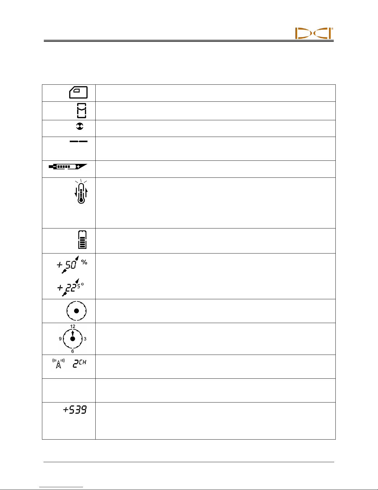
Receiver
Height-Above-Ground Icon – Appears when the height-above-ground function is on and
shows the current height setting.
Locating Icon – Represents a bird’s-eye view of the receiver. This icon is referred to as
the “box” when using the target-in-the-box and line-in-the-box locating techniques.
Target – Represents the front and rear locate points (FLP and RLP). When the receiver is
positioned directly above a locate point, the target will be in the box.
Line – Represents locate line (LL). When the receiver is positioned directly above the
LL, the line will be in the box. The LL also allows for off-track locating when access over
the drill head is limited.
Transmitter Battery – Depicts the battery status of the transmitter.
Transmitter Temperature – Shows temperature status of transmitter. An arrow appears
next to the thermometer pointing either up to indicate increasing temperature, or down to
indicate decreasing temperature. The three curved lines extending from the top of the
thermometer appear if the transmitter has reached a dangerous temperature of 111°F or
43°C and requires immediate attention. The thermometer will flash off and on at 118°F
(48°C) to further indicate the need for immediate action to cool the thermometer. The
actual temperature can be displayed in place of the pitch by holding the trigger in.
Receiver Battery – Depicts the battery status of the receiver.
Transmitter Pitch – Shows the inclination of the transmitter (drill head), displayed in
either percent slope or degrees. The pitch value is shown with a drill head indicator
behind it that points up for positive pitch and down for negative pitch. When using percent
slope for pitch measurements, a value from 1 to 100 will appear; when using degrees, a
value from 0 to 45 will appear, followed by a decimal point and a value of 0 or 5. Pitch
measurements are given in 0.5-degree increments.
Pitch/Roll Update Indicator - The dot in the center of the clock should blink 2 times per
second, indicating that current pitch, roll, battery, and temperature information is being
received from the transmitter.
Transmitter Roll – The clock shows the 12 roll positions of the transmitter.
Telemetry Channel Setting – Shows the current channel setting for the receiver. The
receiver must be set to the same channel as the remote display. There are eight channel
settings (1, 2, 3, 4, 5, 6, 7, 8) and an Off setting.
+/–
Plus/Minus Locating Indicator – The plus or minus sign in front of the signal strength
value can be used to guide the operator in finding the locate points (FLP and RLP) and
the locate line (LL).
Signal Strength – Displays the amount of signal from the transmitter when the trigger is
held in. The signal strength scale ranges from 0 to 999, where 0 indicates no signal and
999 indicates signal saturation (receiver and transmitter are very close). When the trigger
is not held in and the receiver is saturated (too close to transmitter), you will see four
dashed lines ( — — — — ) where the distance/depth number should display.
Standard Display Screen Symbols
14 DigiTrak®
L
Operator’s Manual
T
™
Page 15
Receiver
Drill
Receiver
Transmitter
Drill
Receiver
Transmitter
Level Receiver Not Level Receiver
Power On/Off
On – To turn the LT receiver on, pull and hold the trigger in for 2 seconds and release. You will briefly see
a test screen, followed by a set of numbers that represent the firmware version in the receiver. Then you
will go to the standard locating mode display screen.
Off – To turn the unit off, you must first access the menu choices (see “Receiver Display Menus”). Click
the trigger until you reach the power on/off menu , then hold the trigger in during the countdown from
3 to 0 to shut the receiver off.
Automatic Shutoff – The receiver will automatically shut itself off if no signal is received for 15 minutes.
Note that when the receiver power is turned off, the height-above-ground function is also turned off. If you
want to use the height-above-ground function, you must turn it on and reset (if needed) the value after
you turn on the receiver.
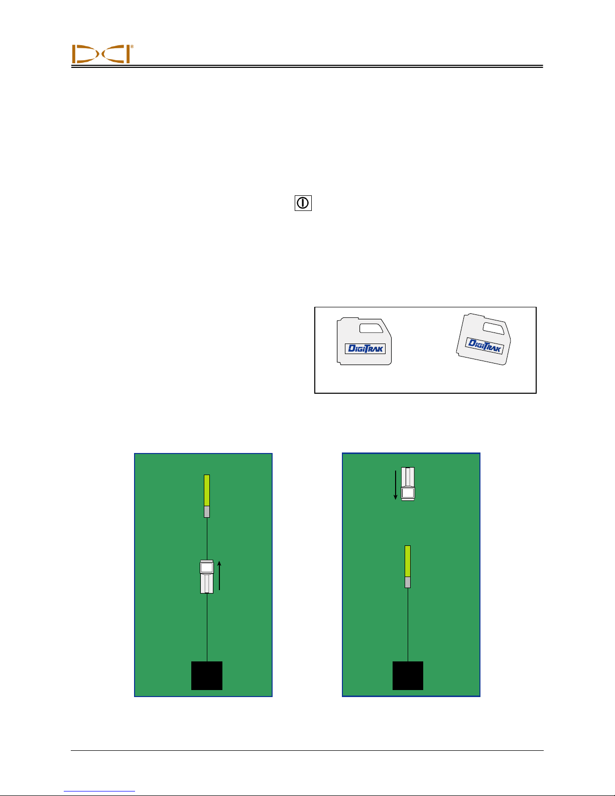
Proper Handling of Receiver
The receiver must always be held correctly to obtain
accurate readings. You must hold the receiver level
at all times and at a constant height above the
ground (see “Height Above Ground” discussion
later in this section).
You can hold the receiver so that it faces in the same direction as the transmitter (away from the drill) or
in the opposite direction, facing toward the drill (see figures below). For an accurate depth reading, you
must hold the receiver parallel to the transmitter and directly above it.
Receiver Facing Away from Drill Receiver Facing Toward Drill
DigiTrak®
L
Operator’s Manual 15
T
™
Page 16
Receiver
Accessing and Changing Menu Settings
To access the LT menu functions, you simply click the trigger. Each trigger click advances you to the
next menu item. When you stop at a menu, you will see a number that indicates a countdown sequence.
To change a menu setting, you hold the trigger in while the counter goes down to 0. Once the counter
reaches 0, release the trigger and the menu setting will be changed, which is indicated by a checkmark at
the bottom of the screen (). If the change was not successful, you will see a checkmark with a slash
through it ( ). The display will then go back to the standard locating display screen.
When in the standard locating mode, you hold the trigger in to display the signal strength in place of the
depth reading and the transmitter temperature in place of the pitch value. You will also see the telemetry
channel setting in the location where the height-above-ground value is normally shown. When using the
standard locating method, you leave the trigger out and move the receiver to position the target or line
symbol in the box. You can use the standard method of finding the locate points and locate line to find the
transmitter, or you can use the plus/minus ("+/–") locating method, which requires you to hold the trigger in
to locate the transmitter (see Locating Instructions section).
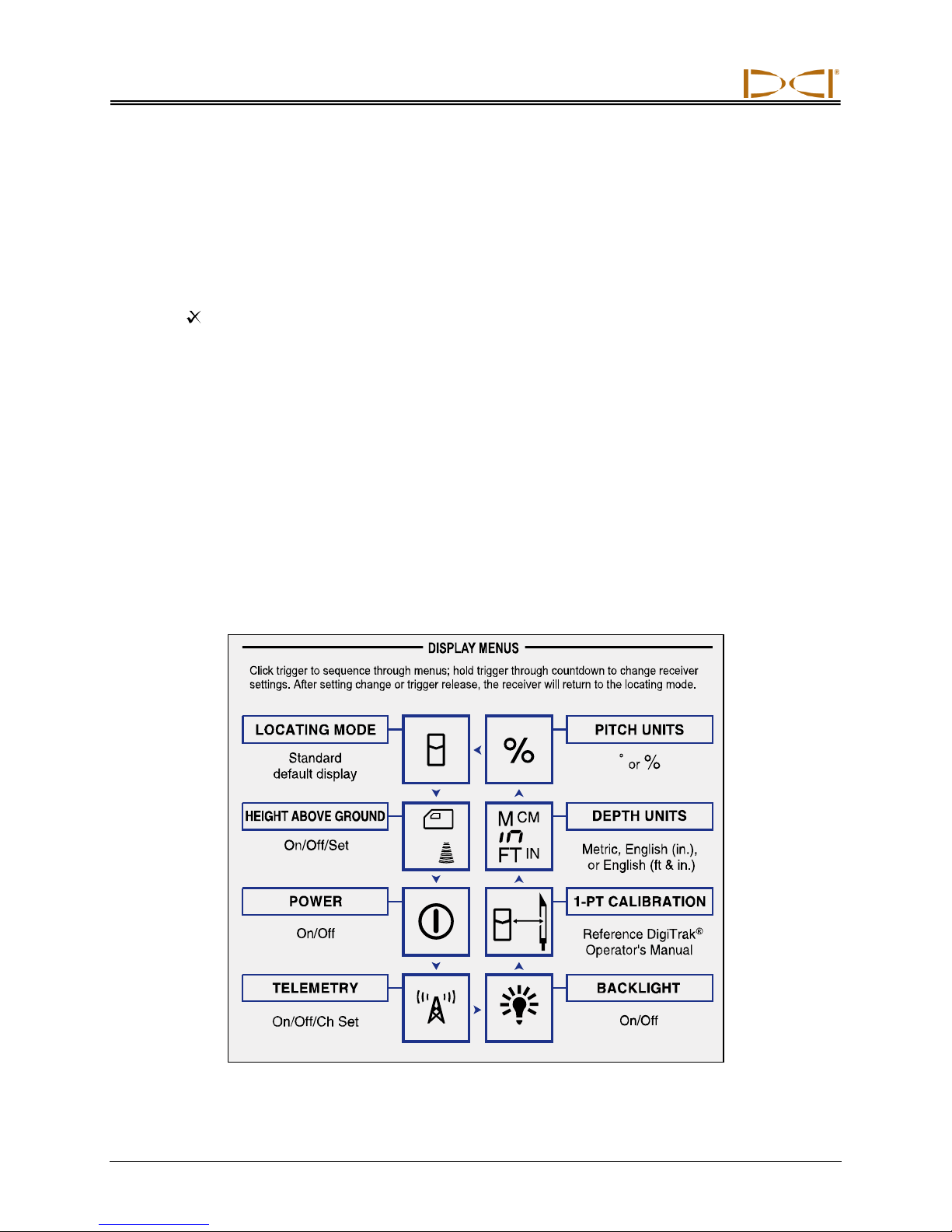
Receiver Display Menus
The front label on the LT receiver shows the display menus (see figure below). This section describes
each menu function and gives instructions for how to change the menu settings. The menus are listed in
the order that they appear on the front label of the receiver, starting with the height-above-ground menu.
The locating mode is the standard default display that you will see when you turn on the receiver.
Receiver Display Menus as Shown on Front Label
16 DigiTrak®
L
Operator’s Manual
T
™
Page 17
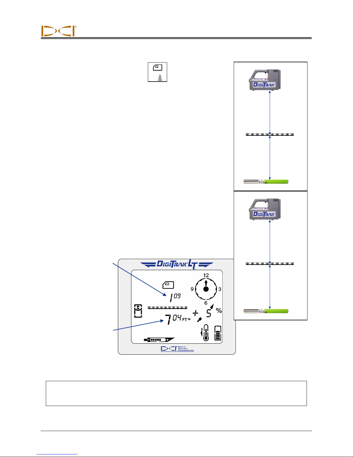
Receiver
Height-Above-
Ground Setting
Distance to
Transmitter
Height
Above
Ground
Transmitter
Depth
HEIGHT ABOVE GROUND
This display menu allows you to enter a height-above-ground measurement so that you can measure the transmitter depth without having to
place the LT receiver on the ground. If the height-above-ground
function is not on, then you must place the receiver on the ground to
take depth measurements.
The height-above-ground value can be set from a distance of 1 ft (12
in. or 30 cm) up to a maximum value of 3 ft (36 in. or 90 cm), depending upon the depth units you selected (FTIN for feet/inches; “in” for
inches only; and MCM for meters/centimeters—see discussion of depth
units menu later in this section). You will see the default height-aboveground distances for the three depth options as 100 for 1 ft 0 in.; “12 in”
for 12 inches; or 030 for 0 m 30 cm. When using the “Set” option
described later in this section, the units of measure will increase by 1in. increments if using English units and by 2-cm increments if using
metric units.
The height-above-ground function can also be helpful when the depth of the tool is shallower than 28 in.
(71 cm). If the receiver is placed on the ground in this situation, it will be saturated with signal and you will
not see a depth number. Instead you will see four dashed lines ( — — — — ) where the distance/depth
number should display.
When the height-above-ground function is enabled, you will see the height-above-ground value on your
locating screen, as shown in the following figure. You must hold the receiver at this height to get accurate
depth measurements.
Locating Mode Display with 1-ft 9-in. Height Above Ground
NOTE: When you turn off the receiver, calibrate, or change the depth units, the height-above-
ground function automatically turns off and the current height-above-ground setting is
deleted.
DigiTrak®
L
Operator’s Manual 17
T
™
Page 18
Receiver
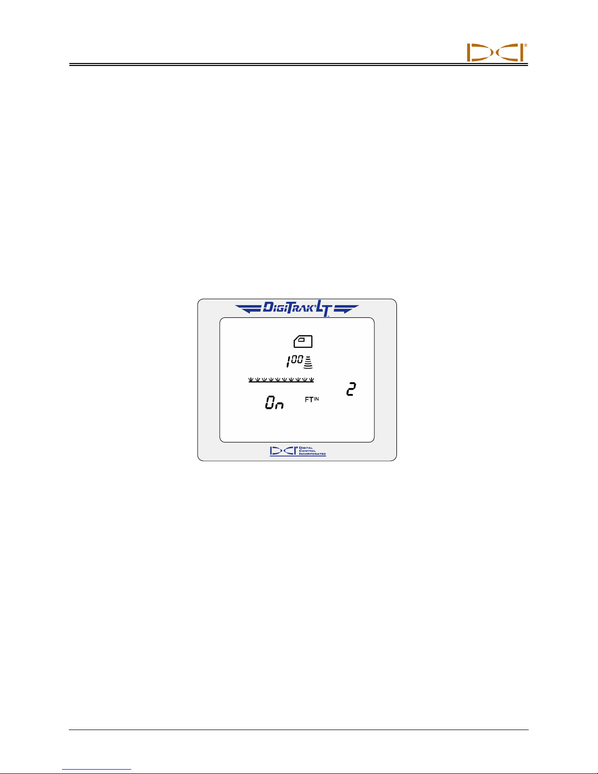
There are three options in the height-above-ground menu:
“On” turns on the height-above-ground function and sets it to the last value that was used.
“Off” turns off the height-above-ground function.
“Set” allows you to set or change the height-above-ground value.
When you enter the height-above-ground menu, the “On” option is the first of the three settings for the
height-above-ground function.
To turn on the height-above-ground function:
1. From the locating screen, click the trigger to advance to the height-above-ground menu. You will see
the “On” option displayed as the first setting option. You will also see the last height-above-ground
number that was entered. If you want that number to remain the same, follow these instructions to
turn on the height-above-ground function. If you want to change this number, you must follow the
instructions to set or change the height-above-ground value, described later in this section.
Height-Above-Ground “On” Screen
2. Hold the trigger in through the countdown sequence from 2 to 0.
3. Release the trigger when the 0 is displayed, and a checkmark will briefly appear at the bottom of the
screen indicating this option has been selected. You have now turned on the height-above-ground
function; note that this value is the number that was last programmed. If you want to change this
number, see the instructions below “To set or change the height-above-ground measurement.”
4. Release the trigger, and you will be returned to the locating screen.
To turn off the height-above-ground function:
1. From the locating screen, click the trigger to advance to the height-above-ground menu. You will see
the “On” option displayed.
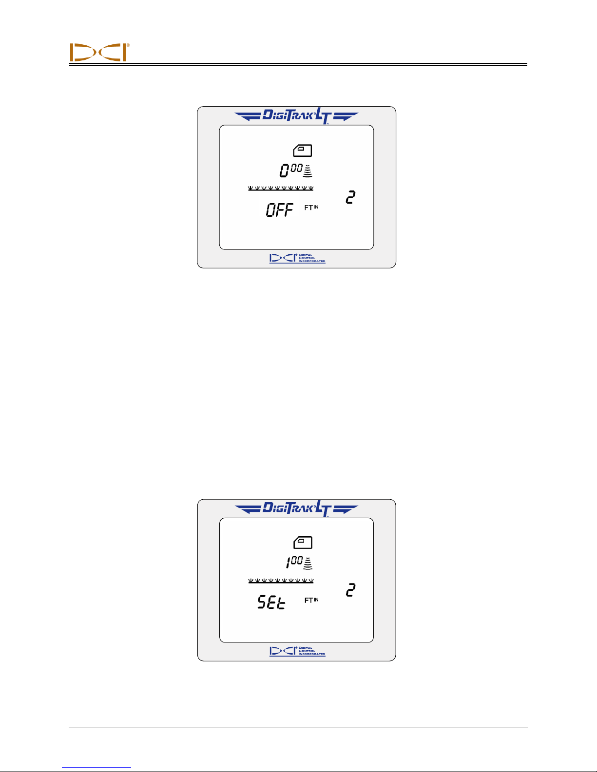
2. Continue to hold the trigger in through the countdown from 2 to 0, and you will then see the “Off”
option displayed.
18 DigiTrak®
L
Operator’s Manual
T
™
Page 19
Receiver
Height-Above-Ground “Off” Screen
3. Continue to hold the trigger in through the countdown sequence from 2 to 0.
4. Release the trigger when the 0 is displayed, and a checkmark will briefly appear at the bottom of the
screen indicating this option has been selected. The height-above-ground function has now been
turned off, and you will be returned to the locating screen. With the height-above-ground function off,
you must place the receiver on the ground for accurate depth readings.
To set or change the height-above-ground measurement:
1. Hold the LT receiver at the height which you intend to hold the receiver.
2. Using a measuring tape, measure the distance from the bottom of the receiver to the ground. This is
your desired height-above-ground measurement.
3. From the locating screen, click the trigger to advance to the height-above-ground menu. You will see
the “On” option displayed.
4. Continue to hold the trigger in through the countdown from 2 to 0, and you will then see the “Off”
option displayed.
5. Continue to hold the trigger in through the countdown sequence from 2 to 0, and you will see the
“Set” option displayed.
DigiTrak®
L
Operator’s Manual 19
T
™
Height-Above-Ground “Set” Screen
Page 20
Receiver
6. Continue to hold the trigger in through the countdown sequence from 2 to 0.
7. Continue to hold the trigger in, and the height-above-ground measurement will display starting at 12
in. (30 cm) and then counting up in 1-inch (2-cm) increments.
8. Once you see the desired height, according to the measurement you made in step 2, release the
trigger, and a checkmark will appear at the bottom of the screen indicating you have reset the heightabove-ground value. You will then be returned to the locating screen.
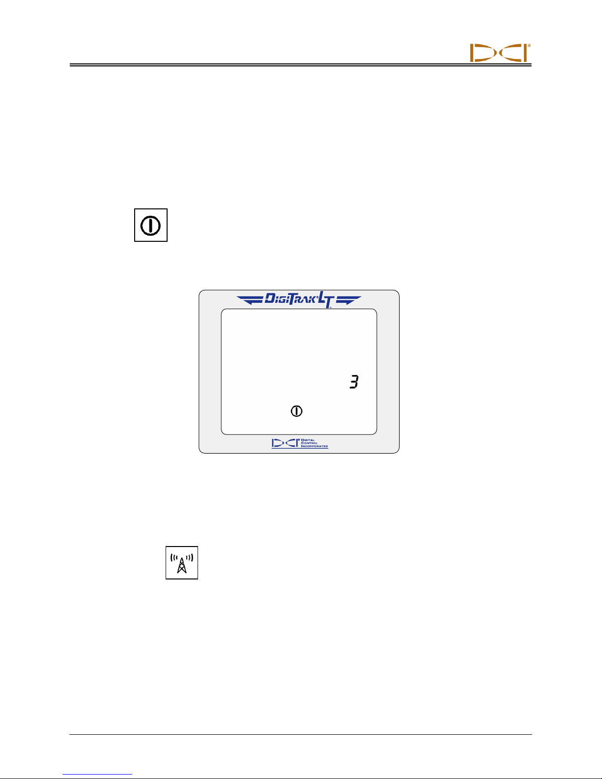
POWER
This display menu allows you to turn off the receiver.
1. Click the trigger to advance to the power menu.
2. Hold the trigger in through the countdown sequence from 3 to 0.
Power Off Screen
3. When the counter reaches 0, you will see a checkmark at the bottom of the display.
4. Release the trigger and the unit will shut off.
TELEMETRY
This display menu allows you to change the telemetry channel setting. This is the channel that the
receiver uses to communicate with the remote display. The receiver and the remote display must be set
to the same channel. There are eight different telemetry channels (1, 2, 3, 4, 5, 6, 7, 8).
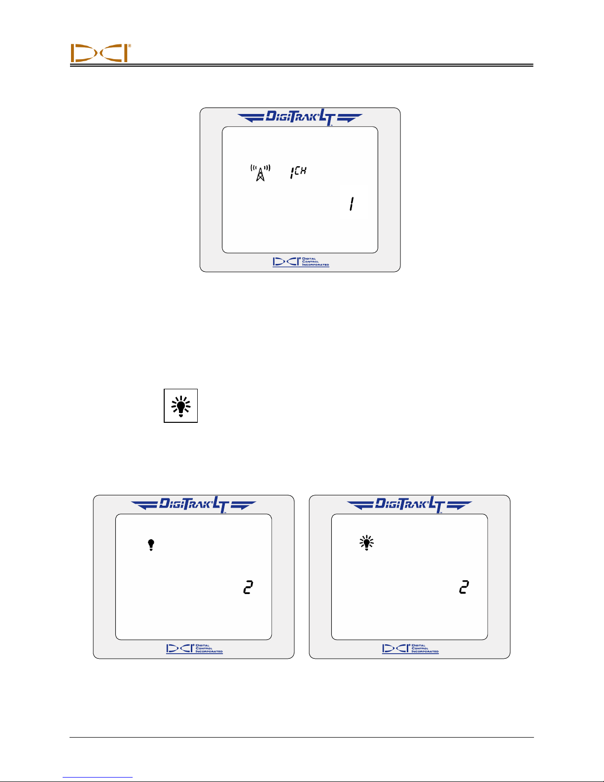
1. Click the trigger to advance to the telemetry menu, where the current channel setting is displayed.
2. Hold the trigger in through the countdown sequence from 1 to 0.
20 DigiTrak®
L
Operator’s Manual
T
™
Page 21
Receiver
Telemetry Channel Setting
3. When the counter reaches 0, you will see a checkmark at the bottom of the display.
4. While still holding the trigger in, the channel settings will cycle through all nine settings—Off, 1, 2, 3,
4, 5, 6, 7, 8.
5. Release the trigger when the correct setting is displayed, and you will return to the locating mode
display screen.
BACKLIGHT
This display menu allows you to turn on or off the display backlight.
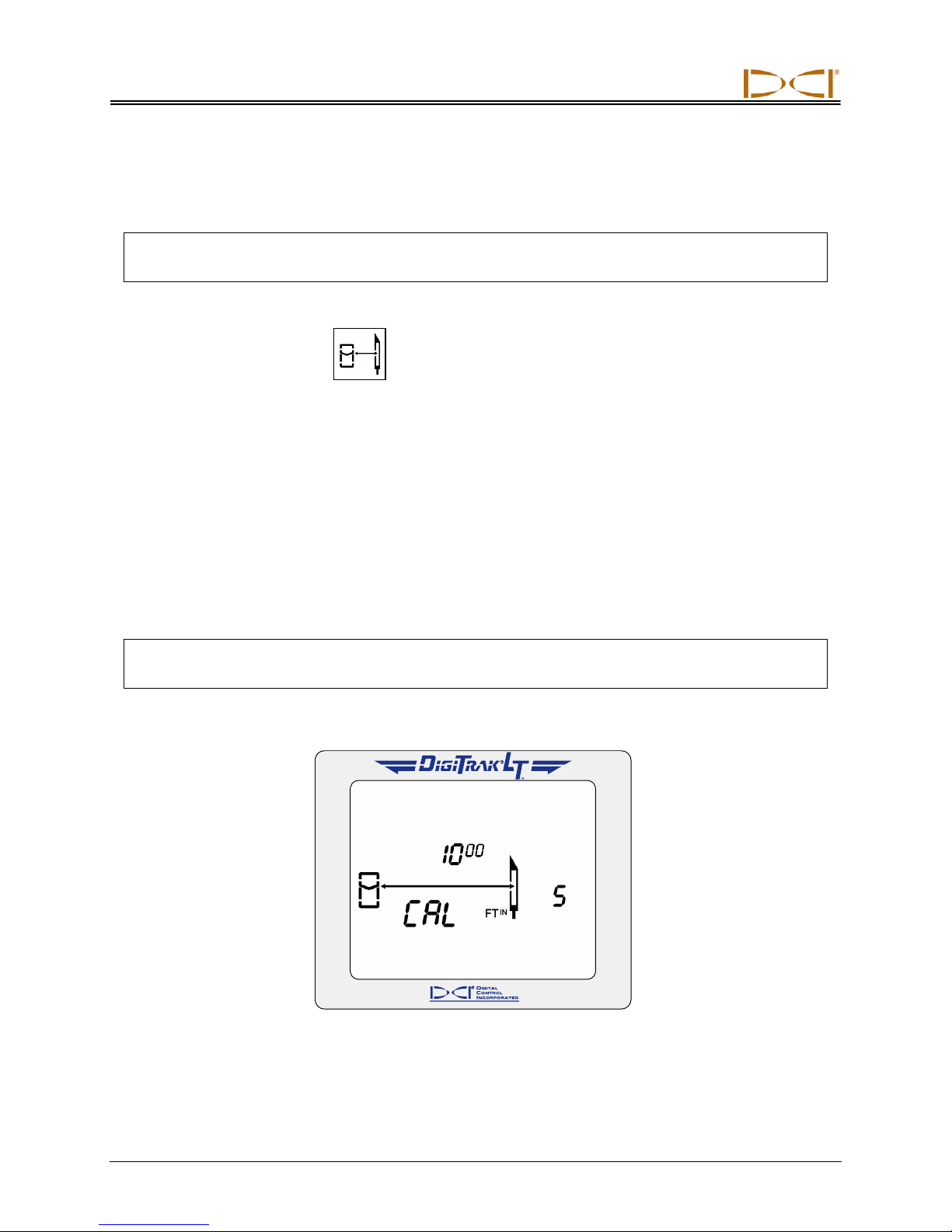
1. Click the trigger to advance to the backlight menu; a light bulb will appear on the display. If the
backlight is on, the bulb will be lit up; if it is off, the bulb will appear unlit.
2. Hold the trigger in through the countdown sequence from 2 to 0.
Backlight Is Turned Off Backlight Is Turned On
DigiTrak®
L
Operator’s Manual 21
T
™
Page 22
Receiver
3. When the counter reaches 0, the light bulb will either light up as the backlight comes on or it will
become unlit and the backlight will turn off.
4. Release the trigger to return to the standard locating mode screen.
NOTE: The backlight automatically comes on for a few seconds at startup, and then it defaults to
the off setting, even if you have reset it previously.
1-PT CALIBRATION
This display menu allows you to calibrate the receiver using the 1-point calibration procedure. The 1-point
calibration procedure is performed with the transmitter in the housing, as described later in this section.
DCI recommends that you verify that the receiver’s depth readings are accurate at several locations using
a tape measure before you drill. Calibration is necessary prior to first-time use and whenever a different
transmitter, receiver, or housing is going to be used.
Do not calibrate if:
You are within 10 ft (3 m) of metal structures, such as steel pipe, chain-link fence, metal siding,
construction equipment, or automobiles.
The receiver is over rebar or underground utilities.
The receiver is in the vicinity of excessive electrical interference.
The transmitter is not installed in the housing.
The transmitter is not turned on.
NOTE: Calibration is necessary prior to first-time use and whenever a different transmitter, re-
ceiver, or housing is going to be used.
The 1-point calibration menu display appears as follows:
1-Point Calibration Screen
22 DigiTrak®
L
Operator’s Manual
T
™
Page 23
Receiver
LT Receiver
(top view)
Transmitter
in Housing
Transmitter
Centerline
10 ft (3.05 m)
LT Receiver
(top view)
Transmitter
in Housing
Transmitter
Centerline
6 ft (1.83 m)
To calibrate the receiver:
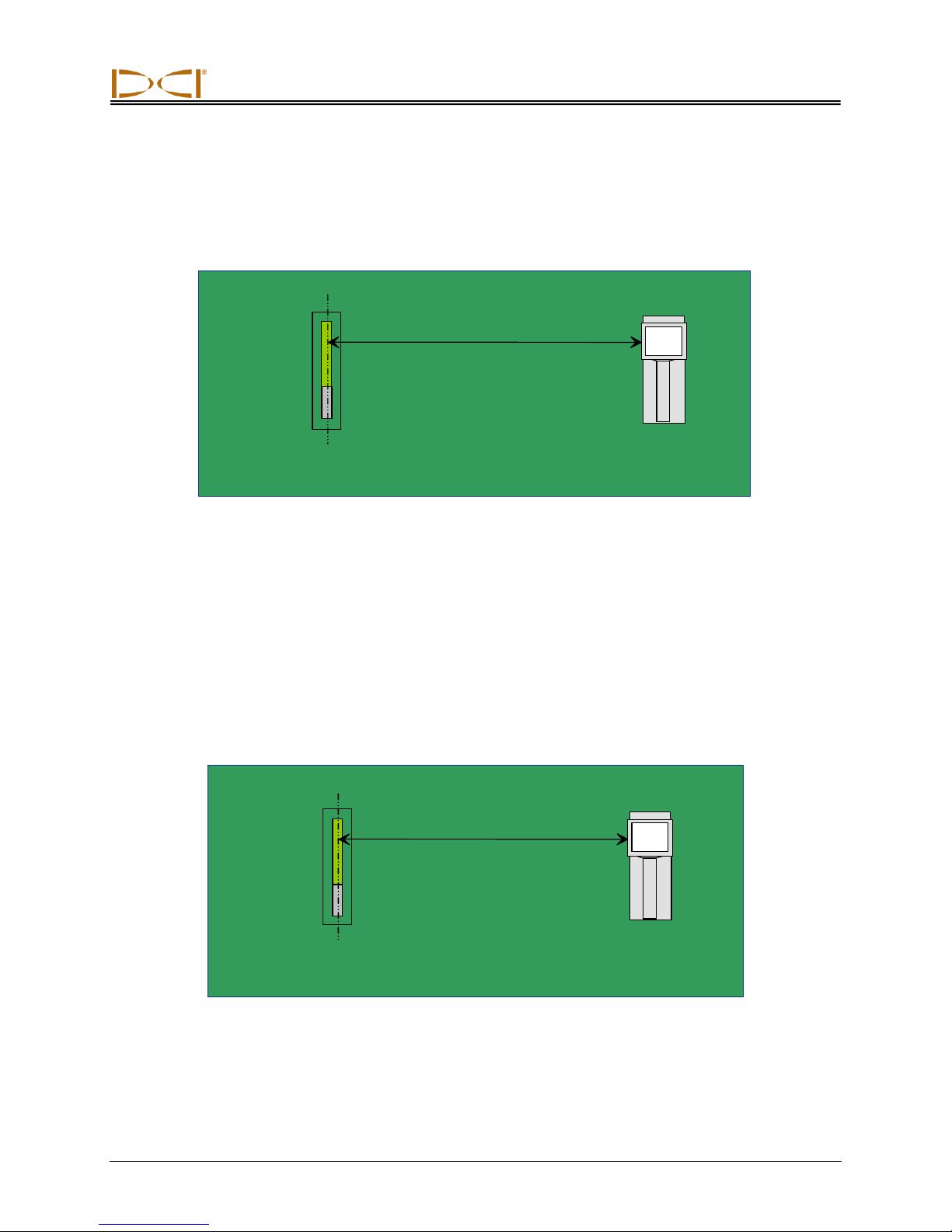
1. Using a tape measure, place the receiver on the ground parallel to the transmitter (in housing) so that
the distance from the centerline of the transmitter to the inside edge of the receiver is 10 ft (3.05 m),
as shown in the figure given below.
Setup for 1-Point Calibration
2. Hold the trigger in on the receiver, and verify that roll and pitch readings are present and that the
signal strength is stable. Then, click the trigger to advance to the 1-point calibration screen.
3. Hold the trigger in while holding the receiver steady through the countdown sequence from 5 to 0.
4. When the counter reaches 0, continue holding in the trigger until you see a checkmark at the bottom
of the display indicating a successful calibration. If you see a checkmark with a slash, then the calibration has failed, and you must repeat steps 1 through 4.
5. After you have successfully calibrated the receiver, you will be returned to the standard locating mode
screen. You must now verify the calibration by checking depth readings at three locations.
6. To verify calibration, place the receiver on the ground parallel to the transmitter so that the distance
from the centerline of the transmitter to the inside edge of the receiver measures a given amount on
the tape measure; in the example shown in the figure below, a distance of 6 ft (1.83 m) is used.
Verifying Calibration
DigiTrak®
L
Operator’s Manual 23
T
™
Page 24
Receiver
7. You should see a depth reading that matches this measured distance, which in our example would be
6 ft (1.83 m).*
8. Repeat the above two steps in at least two more locations.
DEPTH UNITS
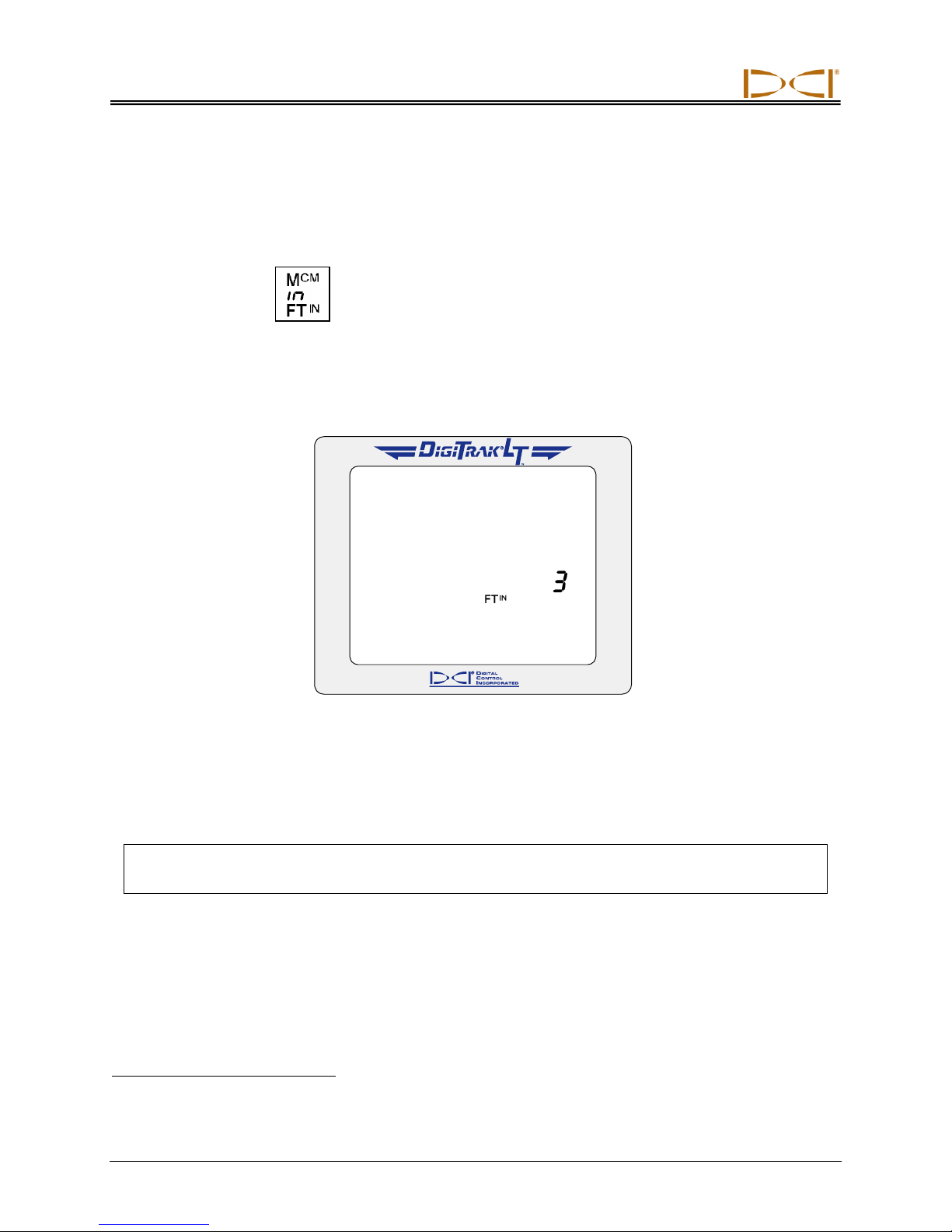
This display menu allows you to set the LT system to display values (depth and temperature) in either
English units (FTIN or “in” and °F) or metric units (MCM and °C).
1. Click the trigger to advance to the depth units menu. The display will indicate the current setting.
2. Hold the trigger in through the countdown sequence from 3 to 0.
Depth Units Display Menu
3. When the counter reaches 0, you will see the unit setting change and a checkmark appear at the bottom of the display.
4. Release the trigger to return to the standard locating screen.
NOTE: The depth units can be set on both the receiver and the remote display. It is recommended
that the receiver and the remote display be set to the same depth units.
*Depth tolerance is 5%; thus, at a distance of 6 ft (1.83 m), the error tolerance is 3.6 in. (9 cm).
24 DigiTrak®
L
Operator’s Manual
T
™
Page 25
Receiver
PITCH UNITS
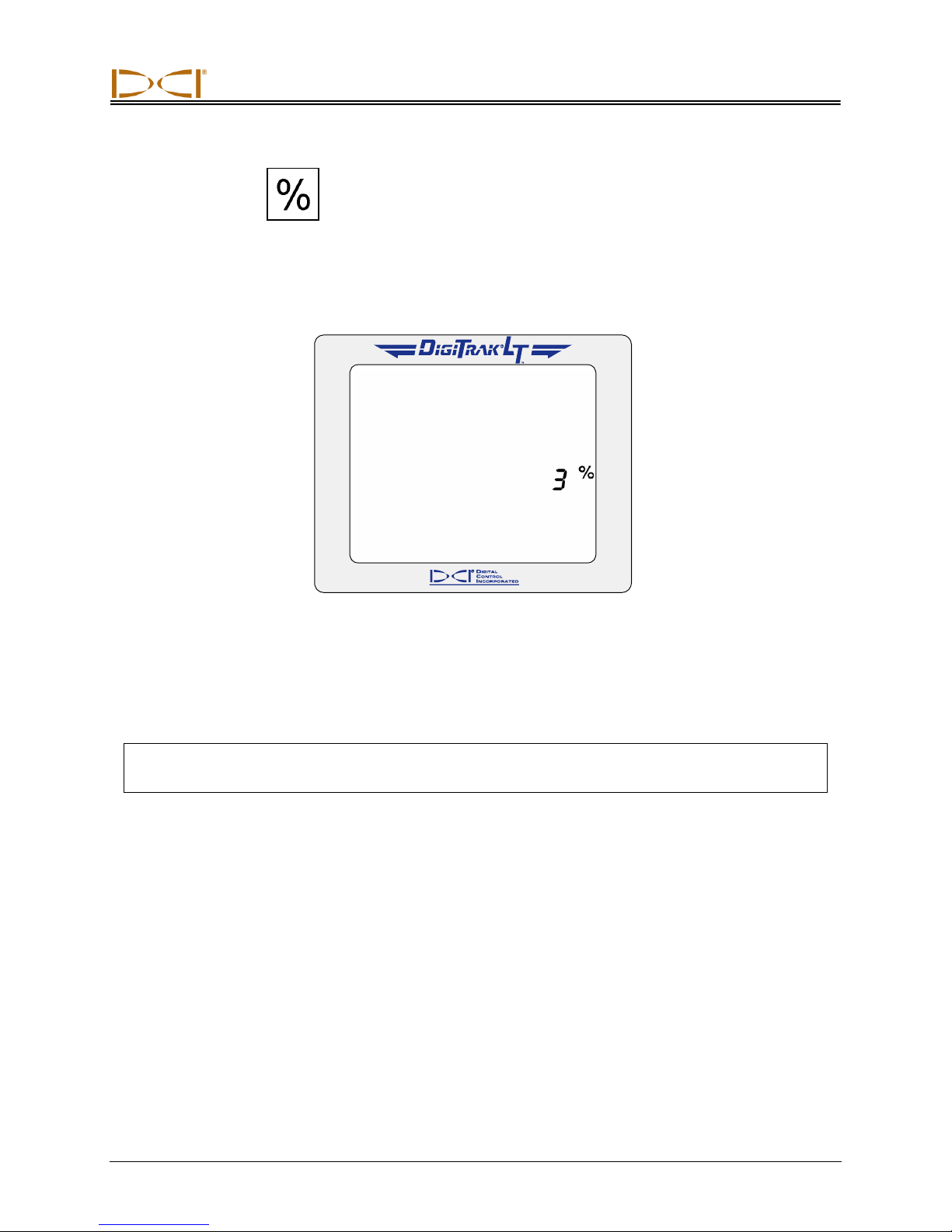
This display menu allows you to set the LT system to display pitch values in either degrees or percent of
slope.
1. Click the trigger to advance to the pitch units menu. The display will indicate the current setting.
2. Hold the trigger in through the countdown sequence from 3 to 0.
Pitch Units Display Menu
3. When the counter reaches 0, you will see the unit setting change and a checkmark appear at the bottom of the display.
4. Release the trigger to return to the standard locating screen.
NOTE: The pitch units can be set on both the receiver and the remote display. It is recommended
that the receiver and the remote display be set to the same pitch units.
DigiTrak®
L
Operator’s Manual 25
T
™
Page 26
DIGITAL CONTROL INCORPORATED
Transmitter
Types of LT Transmitters
The LT transmitter fits inside the drill housing and transmits information regarding the drill head location,
position, and heading. The transmitter emits electromagnetic signals at a frequency of 12 kHz that the
receiver “hears” and converts into the information shown on the receiver and remote display screens.
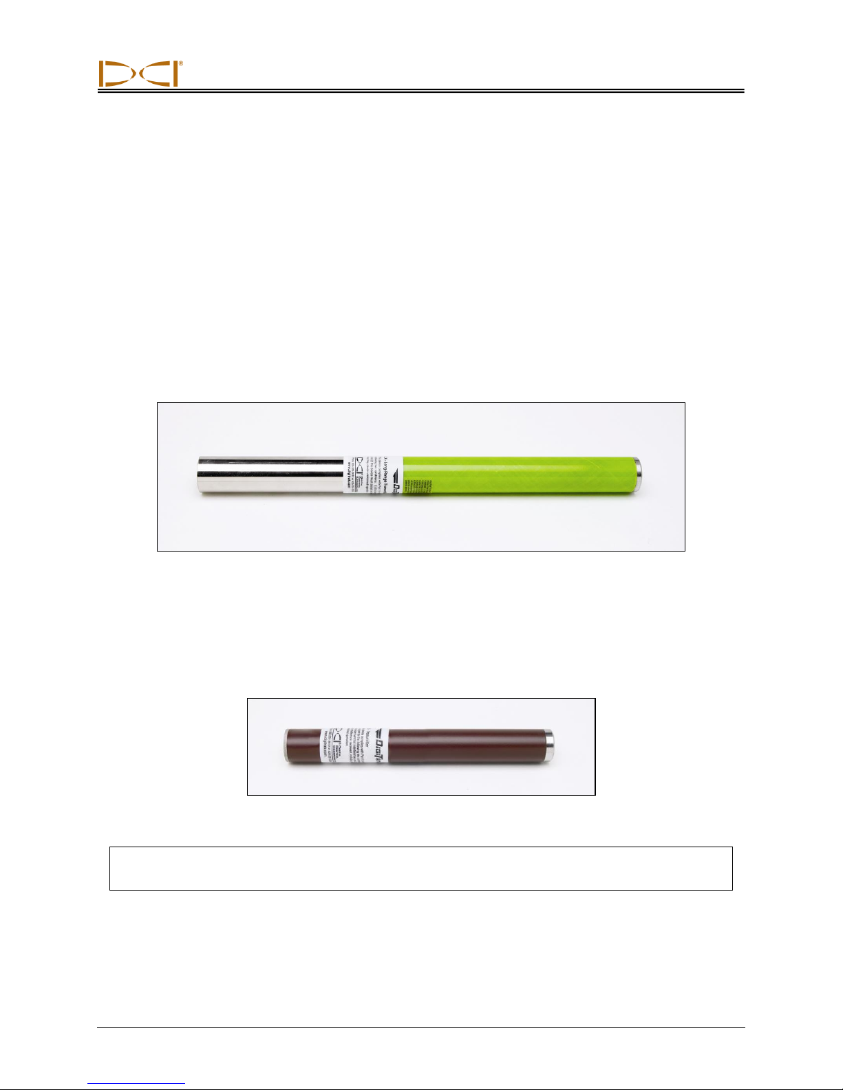
DCI manufactures two different battery-operated transmitters for use with the LT system—a long-range
transmitter (bright-green tube) and a short-range transmitter (brown tube). The long-range (LX) transmitter provides a depth range of 33 ft (10.1 m). The LX transmitter is the size of a standard transmitter—
15 in. (38 cm) long and 1.25 in. (32 mm) in diameter. It is powered by two C-cell alkaline batteries.
Long-Range LX Transmitter
The short-range (LS) transmitter provides a depth range of approximately 15 ft (4.6 m). The LS transmitter is 8.0 in. (20 cm) long and 1.0 in. (25 mm) in diameter. DCI offers an adapter for this transmitter to
fit in a standard-sized housing. The outer dimensions of the adapter with the LS transmitter inside are
exactly the same as those of a standard transmitter (15 in. x 1.25 in. [38 cm x 32 mm]). It is powered by
one AA alkaline battery.
Short-Range LS Transmitter
NOTE: The range of any transmitter with any DCI receiver is dependent upon the amount of inter-
ference at a job site. The range decreases as interference increases.
An index slot at the front end assists in properly aligning the transmitter in the housing. The slot should be
at the 12 o’clock position (with the slot at the top), and the tapered or flattened surface of the drill head
should be indexed to this position.
DigiTrak®
L
Operator’s Manual 26
T
™
Page 27
Transmitter
Front
End
Back
End
8.5 in.
216 mm
2.0 in.
51 mm
Slot Position
Front
End
Back
End
3.75 in.
95 mm
1.25 in.
32 mm
Slot Position
Transmitter Housing Requirements
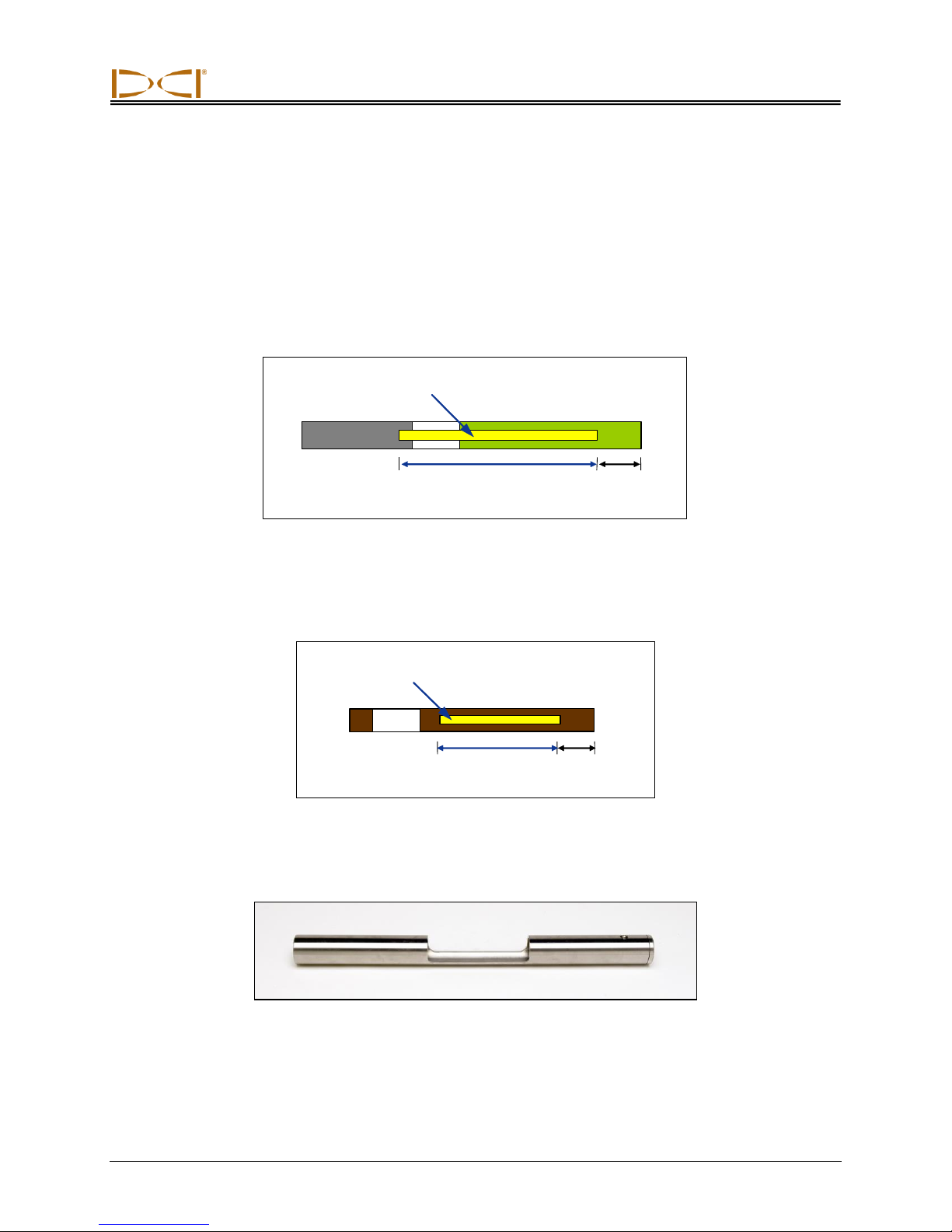
To achieve maximum range and battery life for all of DCI’s transmitters, the slots in the housing must be
long enough and correctly positioned. Slot measurements should always be taken from the inside of the
housing. DCI recommends at least three slots equally spaced around the circumference of the housing.
The slots should be at least 1/16 or 0.0625 in. (1.6 mm) wide.
For the long-range LX transmitter (15 in./38 cm long), each slot should begin at least 2.0 in. (51 mm) from
the front of the transmitter and must be at least 8.5 in. (216 mm) long (see figure below).
Long-Range LX Transmitter Housing Slot Requirements
For the short-range LS transmitter (8 in./20 cm long), each slot should begin at least 1.25 in. (32 mm)
from the front of the transmitter and must be at least 3.75 in. (95 mm) long (see figure below).
Short-Range LS Transmitter Housing Slot Requirements
DCI offers an adapter so you can run the short-range LS transmitter in a standard-sized housing.
DigiTrak®
L
Operator’s Manual 27
T
™
Mini Transmitter Adapter
Page 28
Transmitter
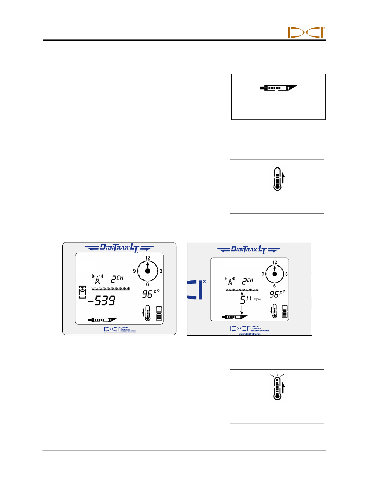
Transmitter Battery Status
Display Symbol
Transmitter Temperature
Display Symbol
Dangerous Transmitter
Temperature Indicator
Transmitter Battery Power
The LT transmitters are battery powered. The long-range LX transmitter is powered by two C-cell alkaline batteries, and the shortrange LS transmitter is powered by one AA alkaline battery.
The transmitter battery icon at the bottom of the display screen continuously shows the status of the transmitter battery power using
progress bars that decrease as the battery power is used.
Transmitter Temperature
The transmitter temperature symbol at the bottom of the display
gives an indication of the temperature, with progress bars and an
up or down arrow. An up arrow indicates the temperature is increasing; a down arrow indicates the temperature is decreasing. A
digital temperature reading can be viewed below the clock in place
of the pitch by holding in the trigger. The drill rig operator can view
the transmitter temperature by holding in the on/off button on the
remote display.
Receiver Display Screen Showing Remote Display Screen Showing
Transmitter Temperature Transmitter Temperature
If the transmitter reaches 111°F (43°C), the transmitter temperature
symbol will change to indicate the transmitter has reached a dangerous temperature—three curved lines will be seen extending from
the top of the thermometer, and the thermometer icon will appear
full, as shown in the figure to the right. When the transmitter’s
temperature reaches 118°F (48°C), the thermometer icon will flash
to indicate immediate action is required to cool the transmitter.
28 DigiTrak®
L
Operator’s Manual
T
™
Page 29
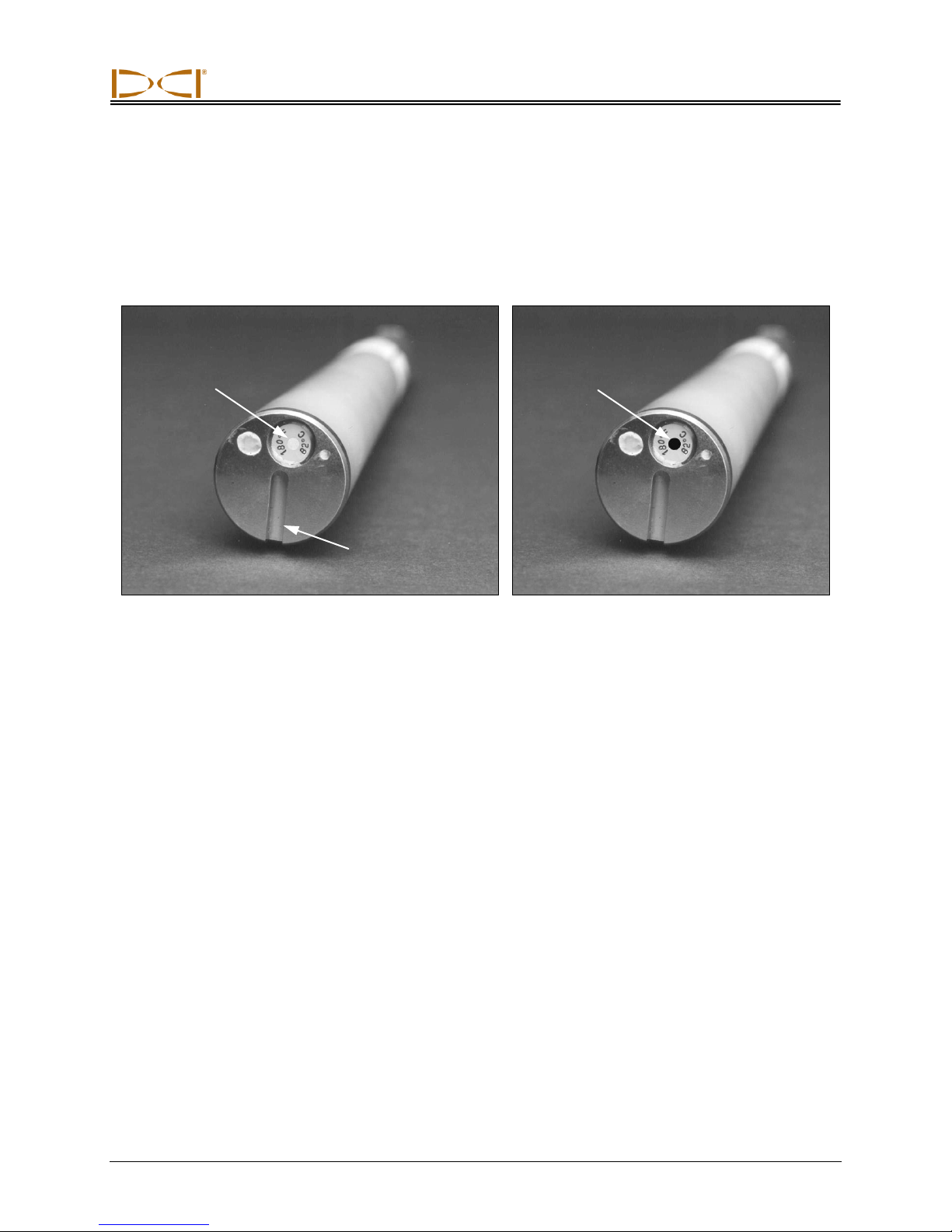
Transmitter
Temp Dot
Index Slot at
6 o’clock Position
Black
Temp Dot
(Overheated)
The transmitter also has a temperature overheat indicator (temp dot) that has an outer yellow ring with a
1/8-inch (3-mm) white dot in the center. This temp dot is located on the stainless-steel front end cap. The
temp dot should be white if the transmitter has not been exposed to excessive heat. If the temp dot is
silver or gray, it indicates the transmitter has been exposed to heat but not in excess of the specifications.
A black temp dot indicates the transmitter has been exposed to temperatures in excess of 180°F (82°C).
The transmitter will shut off at about 176°F (80°C). Drilling should be suspended when temperatures
reach 95°F (35°C) to permit cooling.
Front End Cap of Transmitter Showing Temp Dot, Index Slot, and Black Temp Dot
If the temp dot is black, the transmitter should be considered unreliable. If the transmitter overheats, it
may appear to operate normally; however, exposure to excessive temperatures greatly increases the
likelihood of inaccurate information and will contribute to premature failure of the transmitter. The DCI
warranty does not apply to any transmitter that has been overheated or that has had the temp dot
removed.
Avoid transmitter overheating by practicing proper drilling techniques. Abrasive soils, clogged jets,
inadequate mud flow, and poorly mixed mud are some of the factors that can contribute significantly to
the risk of an overheated transmitter.
Sleep Mode (Automatic Shutoff)
LT transmitters will shut down (go into “sleep” mode) to conserve battery power if they are stationary for
15 minutes. To “wake up” a transmitter, simply rotate the drill string.
General Transmitter Care Instructions
Clean the springs in the battery compartment and the threads of the battery cap and O-ring.
Emery cloth can also be used to remove any oxidation buildup.
Verify that the transmitter fits snugly in the housing. It may be necessary to wrap the transmitter
with tape or O-rings.
Send in the Product Registration card for the 90-day limited warranty.
DigiTrak®
L
Operator’s Manual 29
T
™
Page 30
DIGITAL CONTROL INCORPORATED
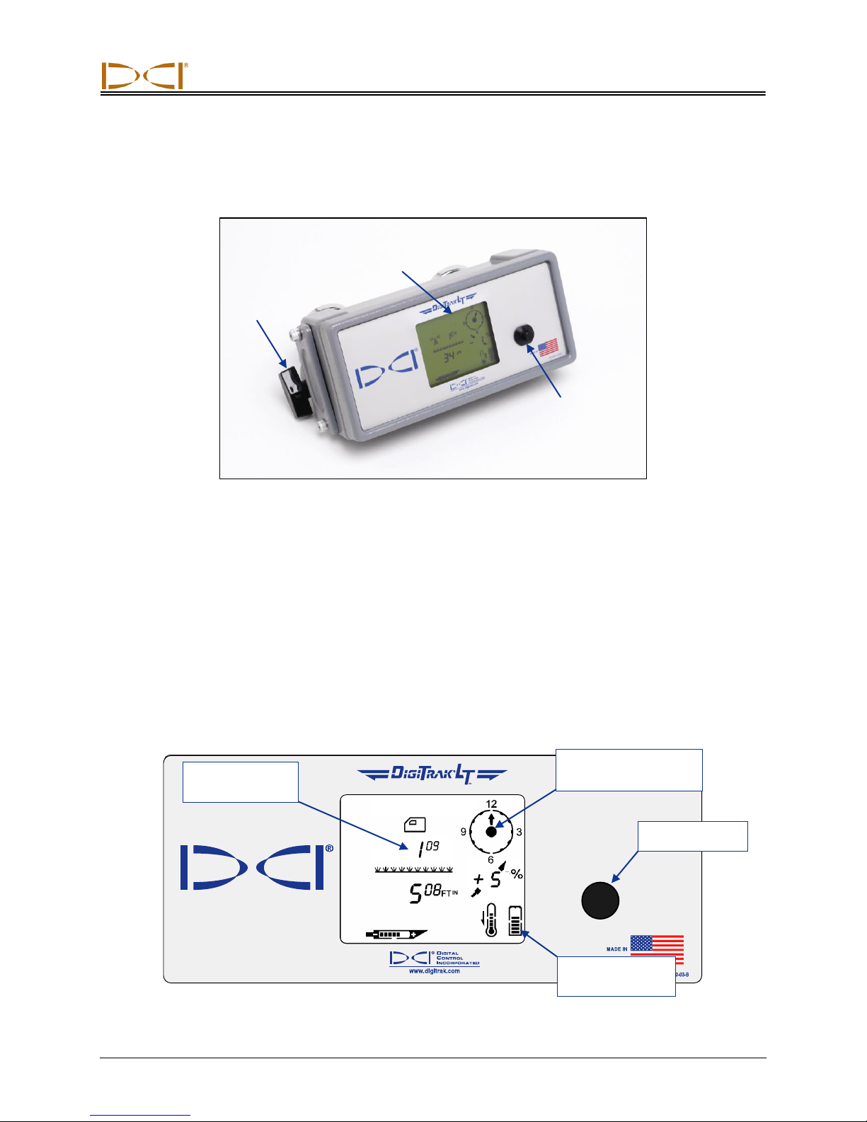
Mounting
Bracket
Display
Window
On/Off
Button
Main Remote Display Screen
Height-Above-
Ground Setting
On/Off Button
Remote Display
Battery Status
Roll/Pitch Indicator
(should be flashing)
Remote Display
DigiTrak LT Remote Display
The DigiTrak LT remote display, which is located at the drill rig, receives signals from the LT receiver and
displays that information on a screen very similar to the receiver display screen. The remote display has a
main display screen and five menu options (power on/off, telemetry channel settings, backlight on/off,
depth unit selection, and pitch unit selection). The main remote display screen is described below, and
then the menu options are explained.
Main Display Screen
The main remote display screen shows information sent from the receiver in a format very similar to the
display on the receiver. However, the battery status symbol displays the status of the remote display
battery rather than that of the receiver. The on/off button on the remote works similarly to the trigger on
the receiver.
DigiTrak®
L
Operator’s Manual 30
T
™
Page 31
Remote Display
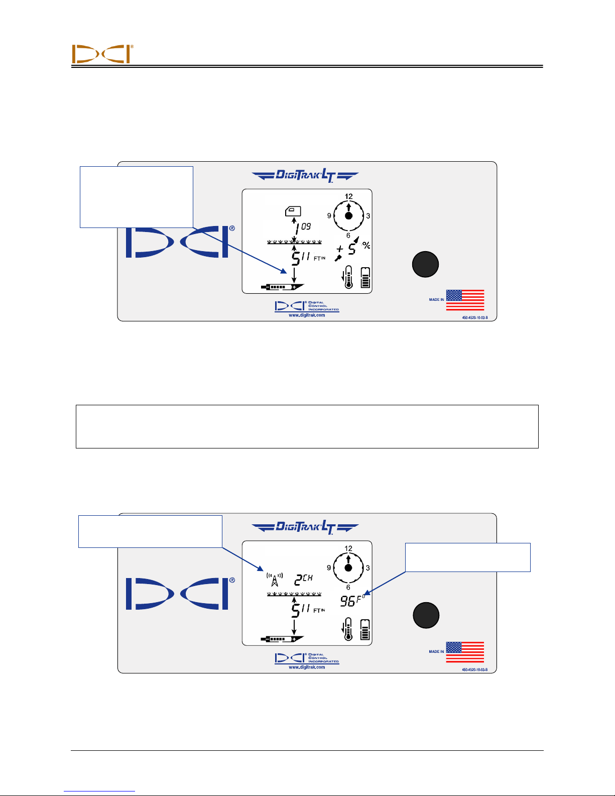
Arrow pointing to tool
head indicates the line
is in the box and the
receiver is above the
transmitter or the LL.
Telemetry Channel Replaces
Height-Above-Ground Setting
Transmitter Temperature
Replaces Pitch Reading
The main display screen indicates when the receiver is over the transmitter or the locate line (LL) by
showing arrows above and below the depth value, as shown below. The receiver display will show the
line in the box.
Depth Reading When Receiver Is Above Transmitter or LL
In this display, the downward arrow is pointing to the transmitter to indicate that the reading is the actual
depth of the transmitter or LL. If there is not an arrow pointing down from the depth reading, then the
depth value shown indicates the slant distance (see Locating Instructions section).
NOTE: If you see four dashed lines ( — — — — ) where the distance/depth number should display,
then the receiver is too close to the transmitter and it is getting saturated with signal (see
“Height Above Ground” menu discussion in the Receiver section).
By holding in the on/off button for 2 seconds or more, the transmitter temperature will display in place of
the pitch information and the telemetry channel will display in place of the height-above-ground setting, as
shown below.
DigiTrak®
L
Operator’s Manual 31
T
™
On/Off Button Held In
Page 32
Remote Display
Remote Display Menus
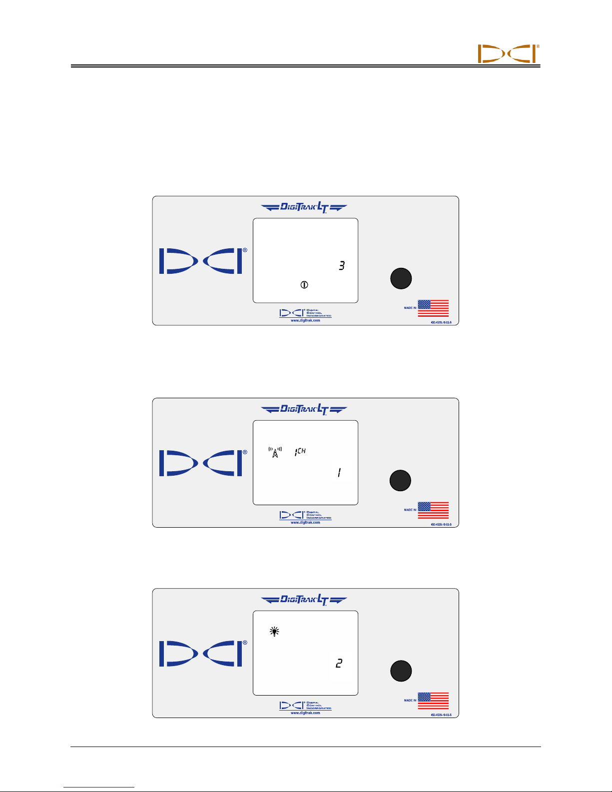
Power On/Off
With the power on/off menu displayed, as shown in the picture below, hold the button in for the countdown sequence from 3 to 0 to turn the unit off. The remote display will automatically shut itself off if no
data is received for 15 minutes.
Telemetry Channel Settings
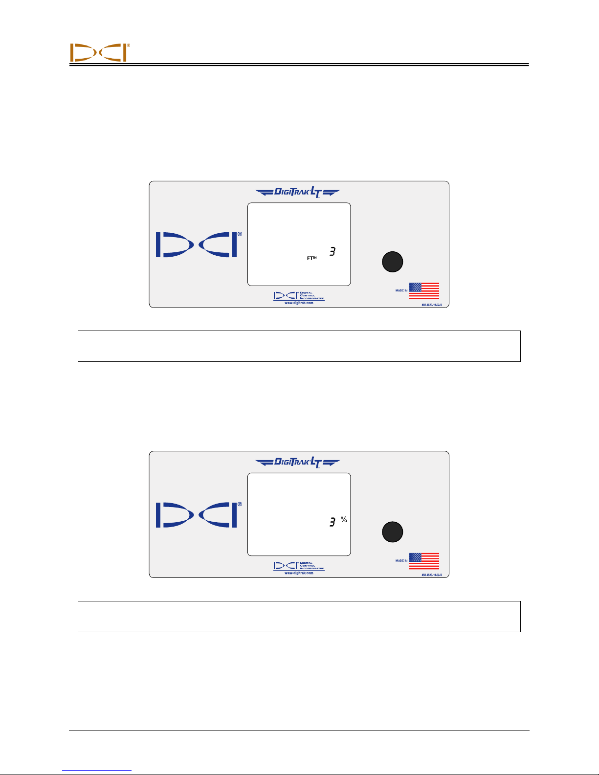
The telemetry channel menu, shown in the picture below, allows you to change the telemetry channel
setting. Hold the button in to cycle through the eight channel options (1, 2, 3, 4, 5, 6, 7, 8), and release
when the desired setting is selected.
Backlight On/Off
At the backlight on/off menu option, shown in the picture below, hold the on/off button in to turn the
display backlight on or off.
32 DigiTrak®
L
Operator’s Manual
T
™
Page 33
Remote Display
Depth Units
The depth units menu, shown in the picture below, allows you to set the remote display to show values
(depth and temperature) in either English (FTIN for feet/inches or “in” for inches only and °F) or metric
(MCM for meters/centimeters and °C) units. Hold the on/off button in to see the current unit setting; to
change the setting, hold the button in for the countdown sequence from 3 to 0.
NOTE: The depth units can be set on both the remote display and the receiver. It is recommended
that the remote display and the receiver be set to the same depth units.
Pitch Units
The pitch units display menu, shown below, allows you to set the LT system to display pitch values in
either degrees or percent of slope. Hold the on/off button in to see the current unit setting; to change the
setting, hold the button in for the countdown sequence from 3 to 0.
NOTE: The pitch units can be set on both the remote display and the receiver. It is recommended
that the remote display and the receiver be set to the same pitch units.
DigiTrak®
L
Operator’s Manual 33
T
™
Page 34
DIGITAL CONTROL INCORPORATED
Rechargeable
Battery Pack
Unexposed Terminal
DO NOT EXPOSE
Positive
Terminal
Negative
Terminal
DC Power
Cord
AC Power
Cord
Control Panel
AC Adapter
Battery Charger
Battery Charger
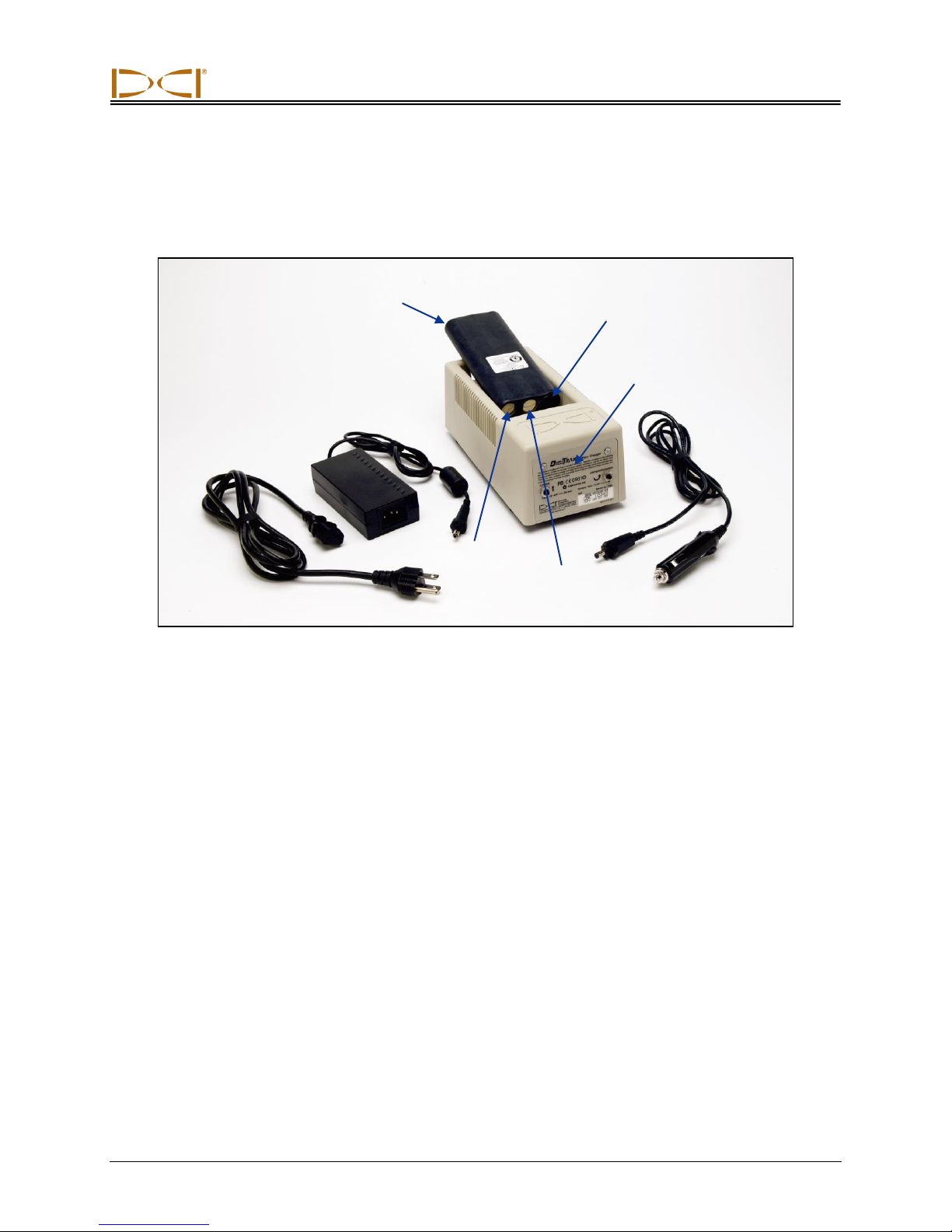
General Description
The DCI battery charger unit, which includes AC and DC power cords and an AC adapter, is provided
with the LT system, along with three rechargeable DCI battery packs. The battery packs are used to
power the LT receiver and the remote display.
The battery charger can operate from AC (100–240 V) or DC (12–28 V) power sources. The battery
charger has specific cords for AC or DC power sources, as shown in the photo above. The AC power
cord is also specific to your global geographic area of operation.
A fully charged battery pack measures between 16.5 V and 17.1 V and will power an LT receiver for
approximately 8 hours or an LT remote display for approximately 12 hours before recharging is required.
A battery is considered discharged at 14.4 V.
Only two terminals are exposed on a battery pack (as shown in above photo). If the third terminal
becomes exposed or the insulating material over the battery shows signs of damage, the battery pack
must be replaced through an authorized dealer.
Charging or using damaged or non-DCI battery packs may damage the charger, the receiver, or the
remote display, and will void the warranty.
DigiTrak®
L
Operator’s Manual 34
T
™
Page 35
Battery Charger
Inserting Charger Plug into Power Port
Red Light:
– Solid indicates unit
is charging.
– Blinking indicates
low-voltage battery
or power interruption.
Green Light:
– Solid indicates
battery is fully
charged.
– Blinking indicates
battery is being
discharged.
Discharge Button
Charge Button
Serial Number
AC/DC Power Setup
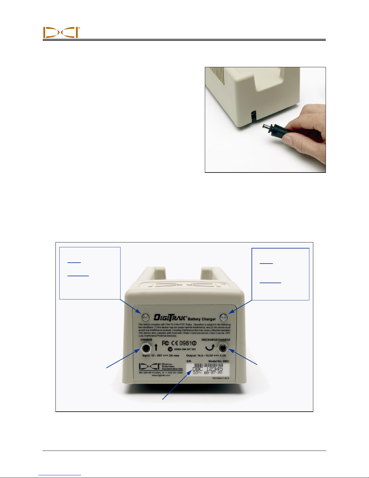
To install either the AC adapter or the DC power cord,
insert the charger plug into the power port on the back
of the battery charger (see photo to right) and rotate a
quarter turn in either direction to lock it in place.
If using AC power, connect the AC power cord to the
power adapter, then plug the cord into the AC power
receptacle (wall outlet).
If using DC power, plug the DC power cord directly into
the DC power receptacle.
Your battery charger is now ready to use.
Charging a Battery
With power supplied to the battery charger, place a battery pack into the charger with the terminal end
making contact with the springs in the battery charger. The red light will illuminate, indicating that the
battery is charging. However, the battery may require discharging to remove any residual charge and
prolong the battery life; DCI recommends that you discharge a battery pack, as instructed in step 2, at
least once a month.
DigiTrak®
L
Operator’s Manual 35
T
™
Battery Charger Control Panel
Page 36
Battery Charger
NOTE: If a battery becomes drained below 4 V, the charger will not immediately recognize the
battery. Leave the battery in the charger and press the charge button. Within a few
minutes, the red light will begin to blink indicating the charger has recognized the
battery. The red light will illuminate solidly within 30 seconds to 1 minute indicating
that the battery is charging on a full cycle.
If the battery needs discharging, press the discharge button on the battery charger; the green light will
begin to blink indicating the battery is being discharged. When the battery is completely discharged,
the green light will stop blinking and the charge cycle will automatically start, as indicated by the solid
red light.
NOTE: The discharge cycle may last for up to 4 hours depending on the amount of residual
charge in the battery. Typically, discharging will last for just a few minutes if the LT
receiver or remote has indicated low battery voltage.
When the charging cycle is complete, the green light will automatically illuminate indicating that the
battery is charged and ready for use. The battery may take up to 4 hours to charge. The voltage on a
fully charged battery is between 16.5 V and 17.1 V.
NOTE: If a battery is left in the charger during a power interruption, the red or green light may
flash and the battery will begin to discharge on its own. After the power has resumed,
simply remove and replace the battery pack.
36 DigiTrak®
L
Operator’s Manual
T
™
Page 37

Notes
Battery Charger
DigiTrak®
L
Operator’s Manual 37
T
™
Page 38
DIGITAL CONTROL INCORPORATED
Locating Instructions
The DigiTrak LT Locating System is easy to use, but there are basic principles that must be understood
before you begin to operate the system. This section gives important information regarding the depth or
slant distance; the locate points and locate line; the geometry of these elements with respect to the
transmitter; and the proper method for marking locate points once they are found. It then describes the
standard locating procedure and an alternate technique referred to as the plus/minus method.
Depth or Slant Distance
When the receiver is held directly above the transmitter, the distance to the transmitter is referred to as
the depth. At any other location, the distance is referred to as the slant distance. When the depth is displayed, there will always be arrows pointing up and down from the depth reading. If the arrows are not
displayed, then the reading is actually the slant distance.
Locate Points (FLP & RLP) and Locate Line (LL)
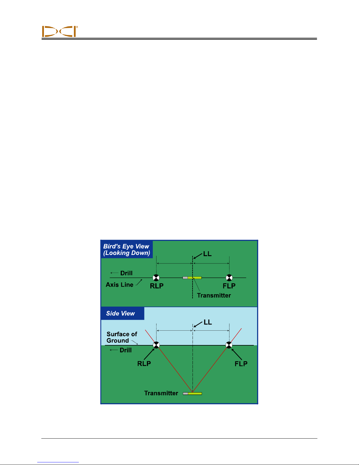
Two of the three locations used for locating are points that represent extensions of the transmitter. One
point is in front of the transmitter (the front locate point or FLP), and the other is behind the transmitter
(the rear locate point or RLP). The third location is a line that represents the position of the transmitter.
This line, referred to as the locate line or LL, is perpendicular to the transmitter.
Geometry of FLP, RLP, and LL from Top and Side Views
Note how the RLP and FLP are equal distances from the LL when the transmitter is level.
DigiTrak®
L
Operator’s Manual 38
T
™
Page 39
Locating
Effects of Depth, Pitch, and Topography on
Distance Between FLP and RLP
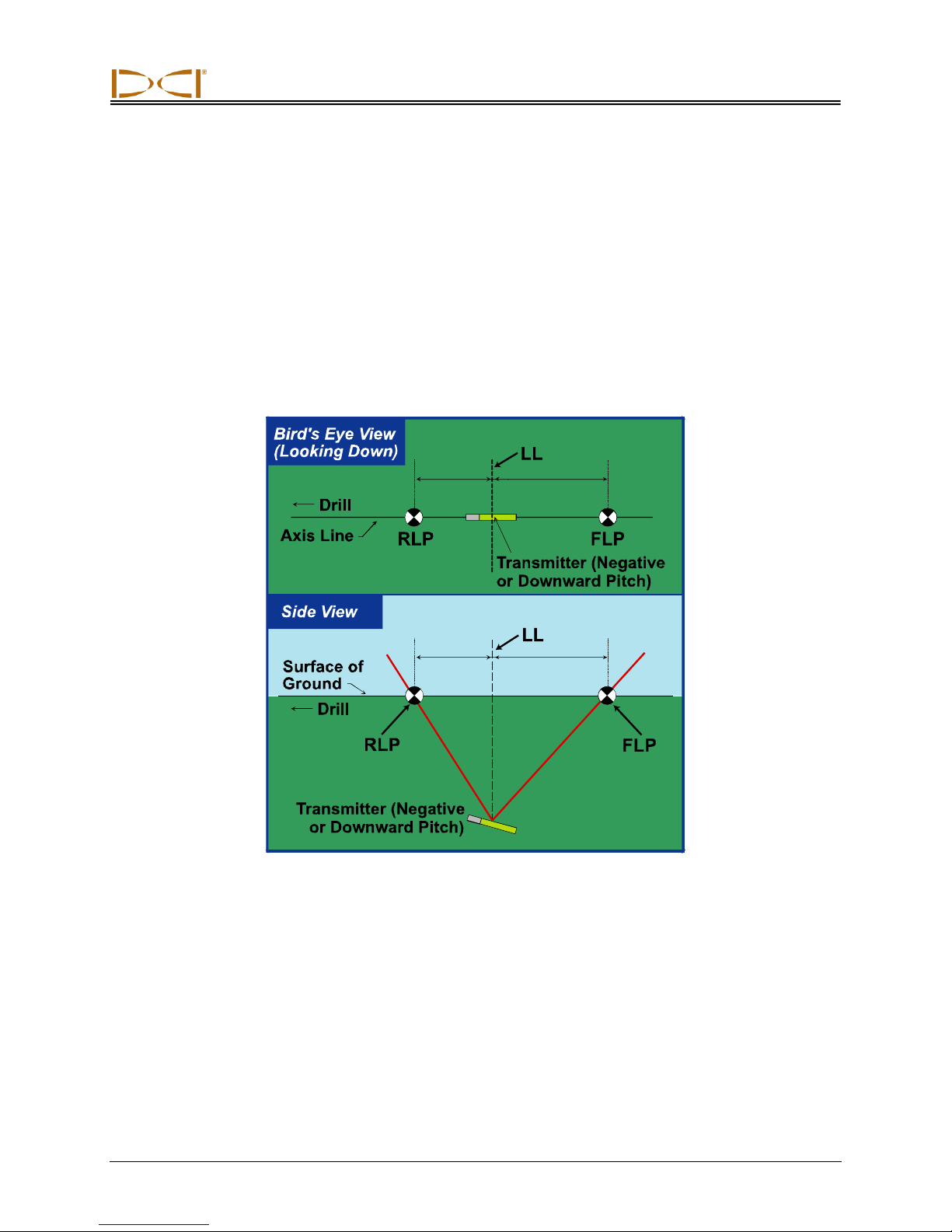
Because of the transmitter’s field shape, the deeper the transmitter is, the further apart the FLP and RLP
will be. The distance between the FLP and RLP with respect to the location of the LL is also a function of
the transmitter pitch and the topography.
When the transmitter pitch is negative, the FLP will be further from the LL than the RLP (see figure
below). When the transmitter pitch is positive, the RLP will be further from the LL than the FLP. If the
ground surface or topography slopes significantly, the locations of the FLP and RLP will also be affected
with respect to the LL even though the transmitter itself is level.
Effect of Pitch on Distance Between FLP, RLP, and LL
Note how the RLP and FLP are at different distances from the LL when the transmitter is
at a negative pitch (compare with figure on previous page in which transmitter is level).
DigiTrak®
L
Operator’s Manual 39
T
™
Page 40
Locating
Center of
Display
Vertical Axis
Place Marker
Straight Down
on Ground
Front of
Receiver
Plumb Line or
Marking Locate Points
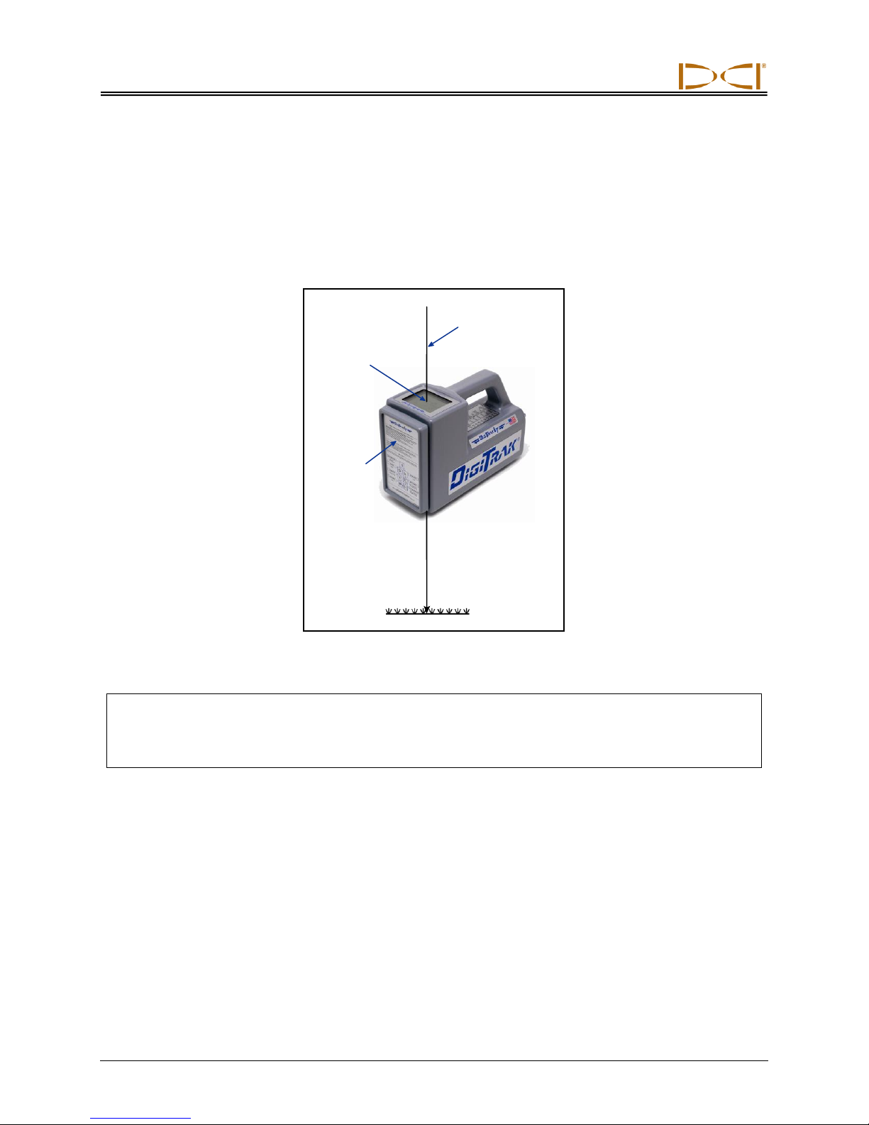
The front and rear locate points (FLP and RLP) and the locate line (LL) must be found and accurately
marked during the locating procedure. To mark a locate position after you have found it, stand with the
receiver level directly above the locate point. Look down the vertical axis that runs through the center of
the display to project a plumb line to the ground. The point where this plumb line hits the ground is the
location that you should mark.
Plumb Line for Marking Locate Points
HANDLING THE RECEIVER
NOTE: It is critical that you hold the receiver correctly to obtain accurate readings. You must hold
the receiver level at all times and maintain a constant height-above-ground distance.
40 DigiTrak®
L
Operator’s Manual
T
™
Page 41
Locating
Locating the Transmitter – Standard Method
With the LT system, you can locate the transmitter and its heading while it moves, whether standing in
front of it, behind it, or toward the side. You can also locate the transmitter facing either toward or away
from the drill rig.
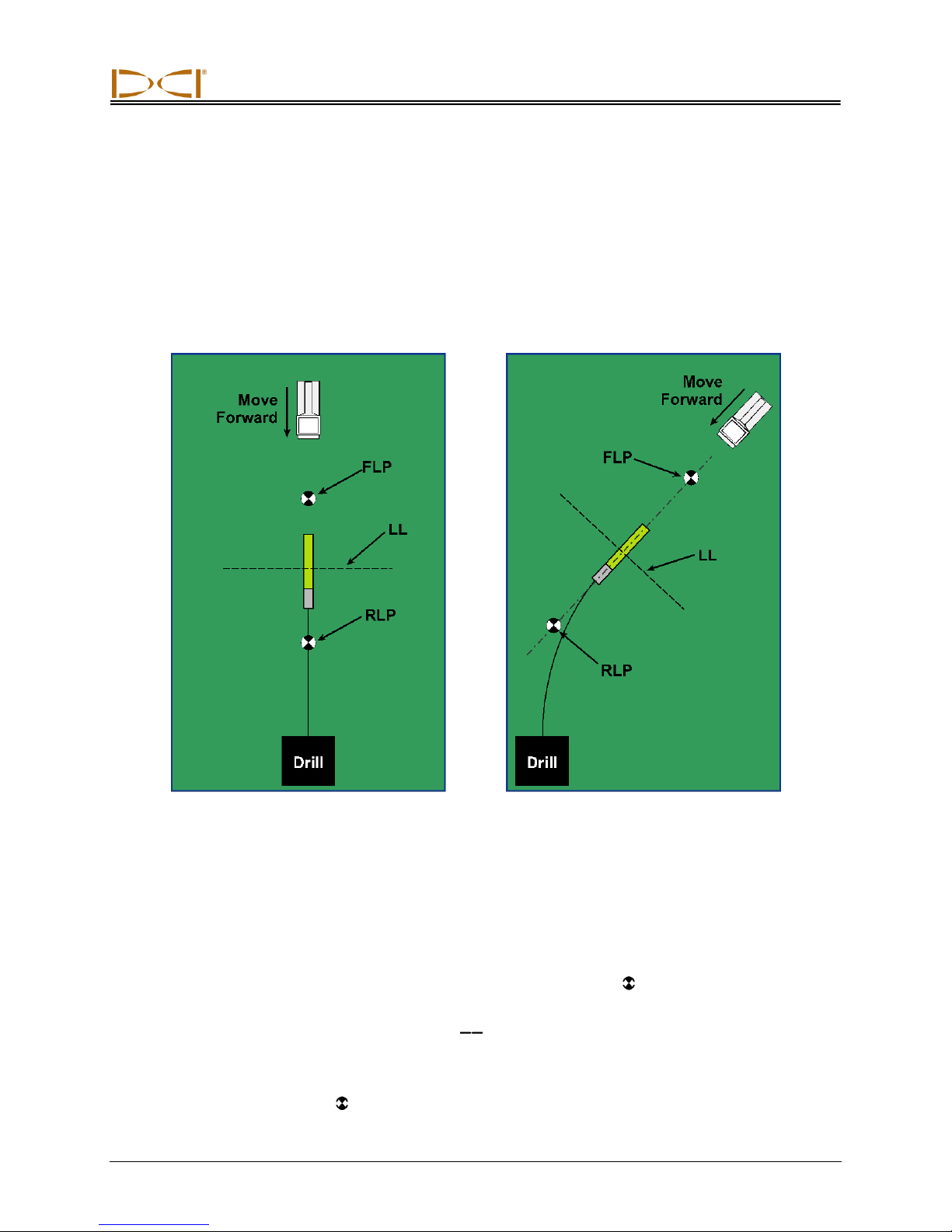
The standard method described in this section guides you to the transmitter while standing out in front of
it, facing the drill rig. This is the recommended method for locating. As you continue to drill or as the bore
path curves, you may be facing the last marked locate point rather than the drill rig.
Setup for Standard Locating Method Standard Locating Method
with a Curved Path
You do not hold the trigger in to view the signal strength when using the standard method. If you want to
view the signal strength (with its associated plus/minus symbols) while locating, please refer to the next
subsection entitled “Plus/Minus (“+/–“) Locating Method.”
The first position to find is the front locate point or FLP. The FLP gives you the transmitter heading. The
FLP’s distance ahead of the transmitter is dependent upon the transmitter depth and pitch; the deeper it
is, the further in front the FLP will be. The FLP is represented as a target ( ) on the receiver display.
Once you have found the FLP, then you will find the LL, where you can determine the depth of the
transmitter. The LL is represented by a short line ( ) on the receiver display. The receiver must be held
parallel to the transmitter when over the drill head to obtain an accurate depth reading.
Then you will find the RLP, where you can confirm the transmitter heading and position. Like the FLP, the
RLP is represented as a target ( ) on the receiver display.
DigiTrak®
L
Operator’s Manual 41
T
™
Page 42
Locating
Finding the FLP
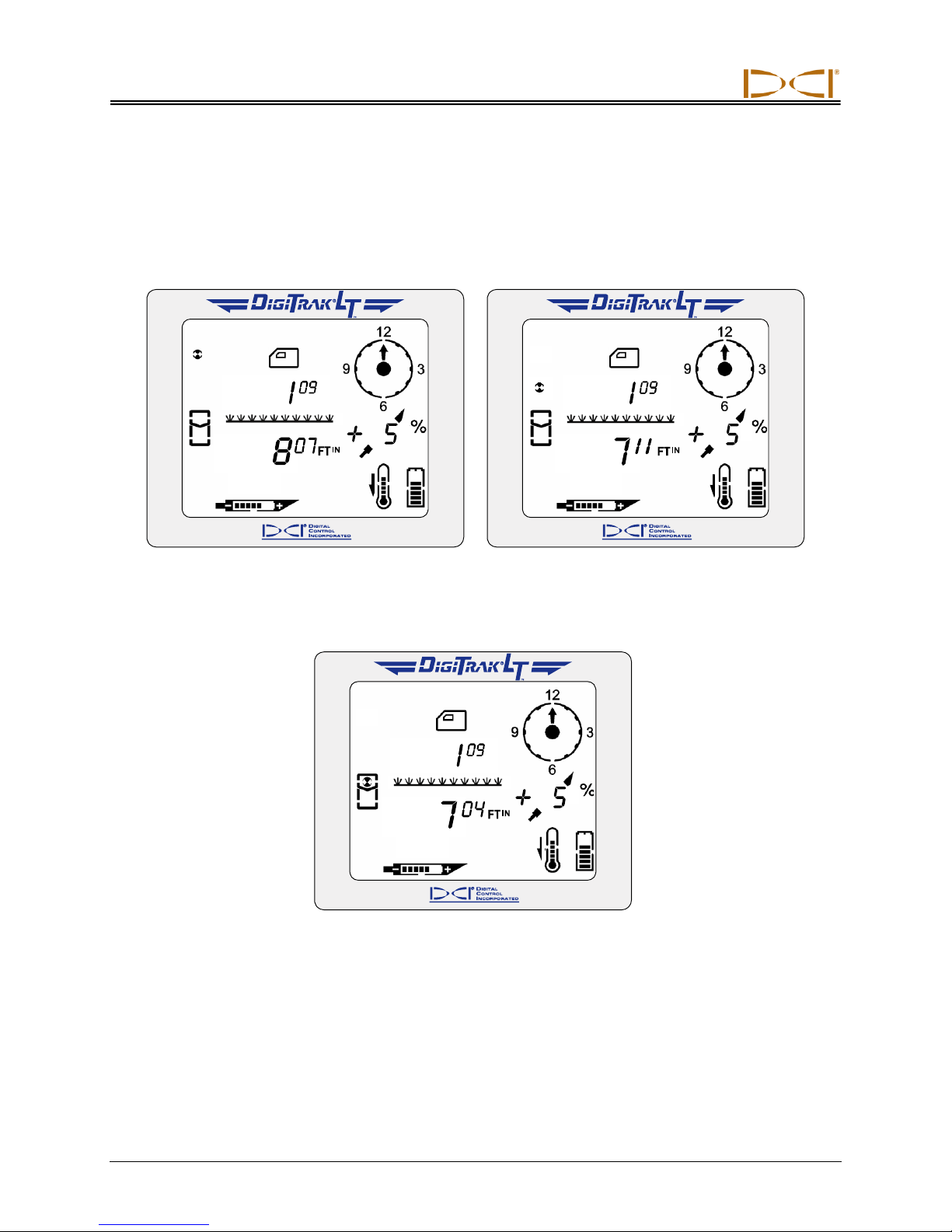
1. Stand out in front of the drill head (facing the drill) at a distance of approximately one drill rod length.
2. As you approach the FLP, the target appears in the top left corner of the display and the depth
number decreases.
Target in Top Left Corner Target Moving Toward the Box
3. Continue to walk forward until the target moves into the locating icon (box).
Target in the Box
42 DigiTrak®
L
Operator’s Manual
T
™
Page 43
Locating
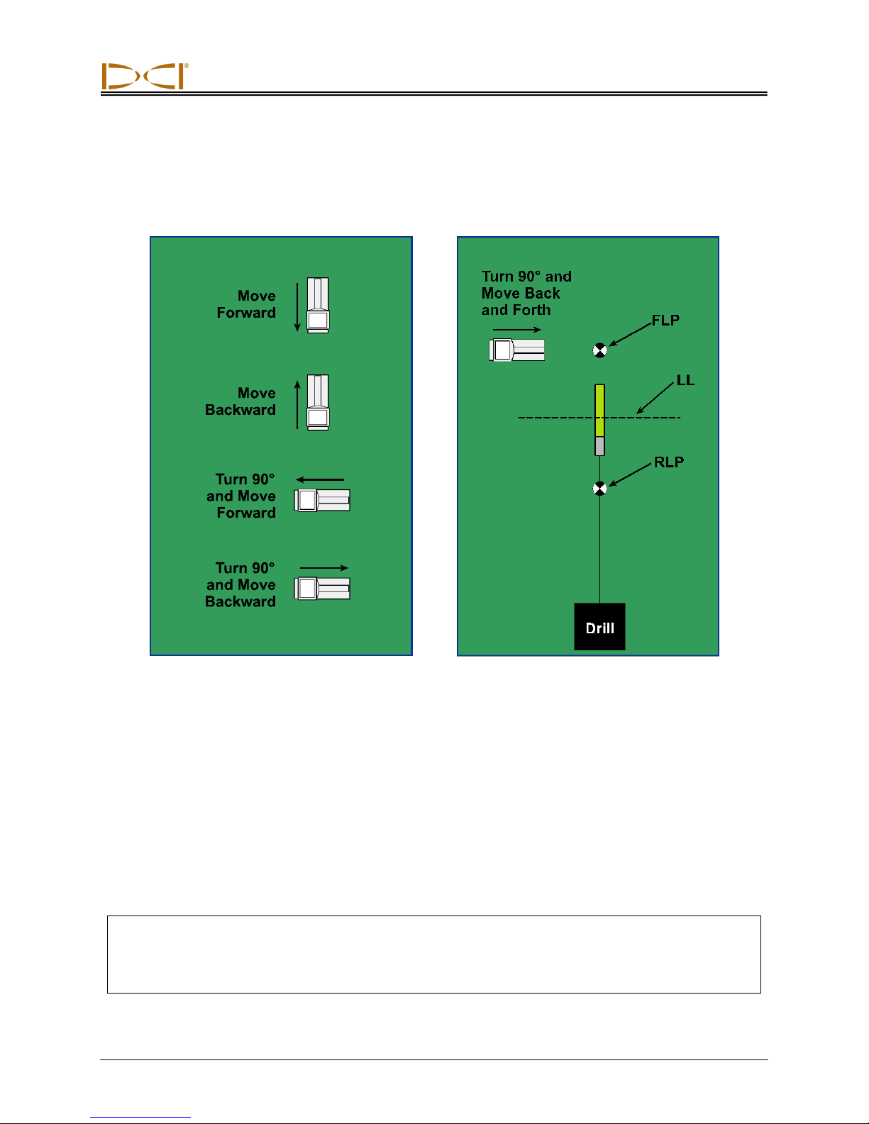
4. Turn the receiver 90° from the transmitter heading while holding the receiver steady and level, and
again center the target in the box by moving the receiver forward or backward as needed. This is the
FLP, which is where the transmitter will end up if it does not get a steering command.
5. Mark the location directly below the display screen as the FLP.
Moving Receiver Back and Forth Turn Receiver 90° and Move Back and
Forth to Center Target in Box
Finding the Transmitter and the LL
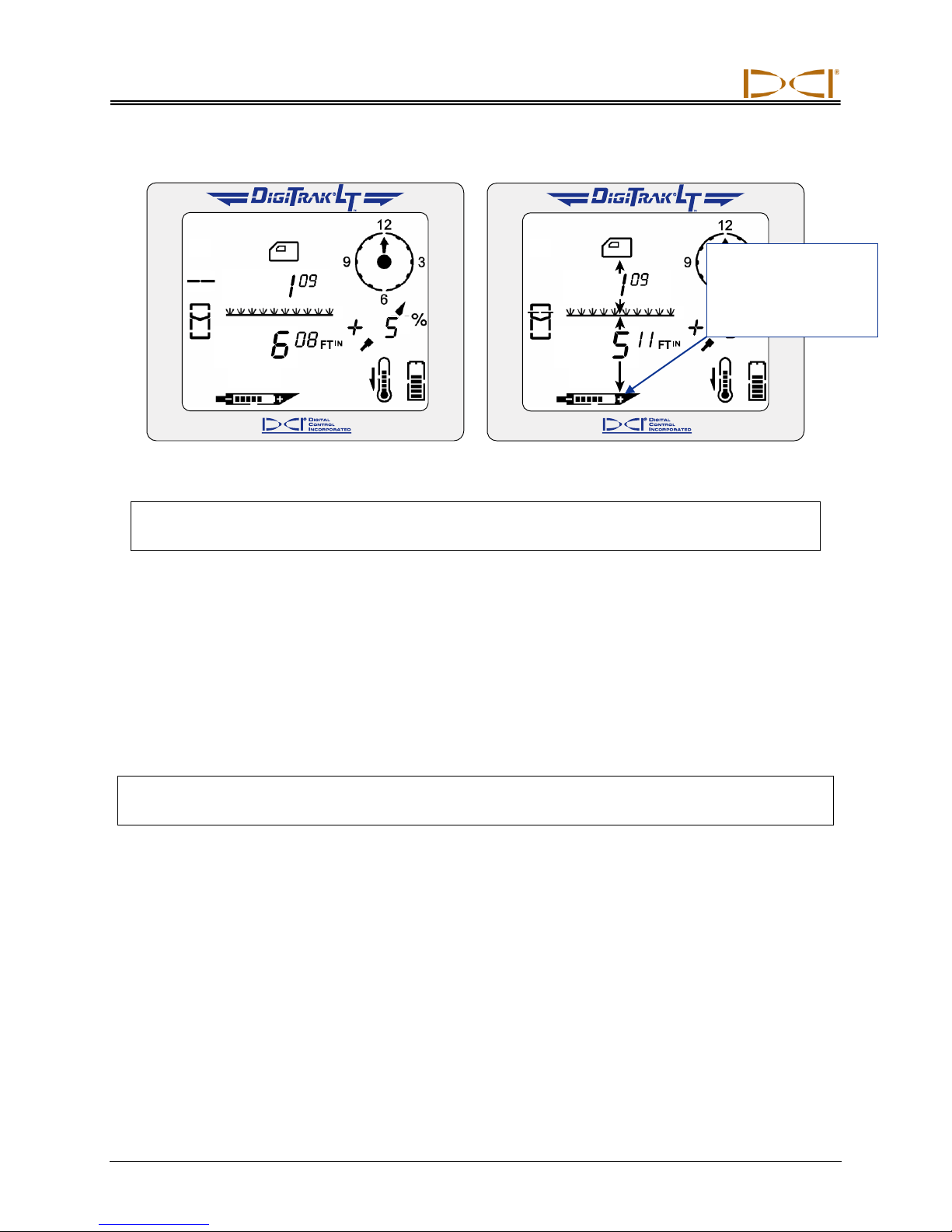
1. At the FLP, turn again to face the drill head (and drill) and walk forward toward the last locate point.
2. Note that the LL appears in the top left of the display.
3. Walk forward and the LL moves closer to the box.
4. Center the LL in the box. You should now see an arrow pointing to the transmitter battery icon, which
indicates that the value is the actual transmitter depth.
NOTE: If the tool is shallower than approximately 28 in. (71 cm) you will see four dashed lines
( — — — — ) where the depth should display. This means that the receiver is too close to
the transmitter and it is getting saturated with signal (see “Height Above Ground” menu discussion in the Receiver section).
DigiTrak®
L
Operator’s Manual 43
T
™
Page 44
Locating
Arrow pointing to tool
head indicates the
line is in the box and
the receiver is above
the transmitter or LL.
LL Moving Toward the Box Line in the Box
NOTE: The arrow that appears below the depth measurement and that points to the transmitter
also appears on the remote display.
5. Mark this location as the LL. You should now be standing above the transmitter.
Confirmation of Exact Heading and Transmitter Position
You can confirm the actual transmitter heading by locating the rear locate point or RLP and then drawing
a line between the RLP and FLP. That line represents the exact heading. Where this line intersects the LL
is the position of the transmitter. Using the locate points and the LL to find the transmitter is more reliable
and efficient than using the peak signal or shallowest depth.
NOTE: Both active and passive interference sources can affect the accuracy of the locate points
and depth readings.
44 DigiTrak®
L
Operator’s Manual
T
™
Page 45
Locating
Finding the RLP
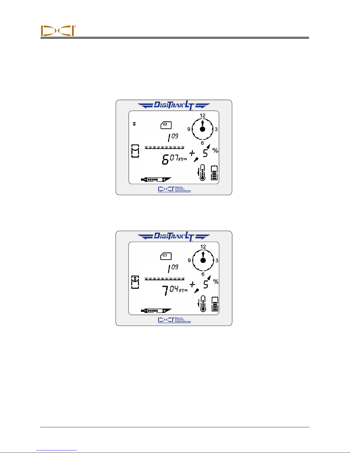
1. While standing above the transmitter still facing the drill, continue walking toward the drill; the target
will appear in the top left corner of the display and the depth will increase.
Target in Top Left Corner
2. Walk forward until the target moves into the box.
Target in the Box
3. Turn the receiver 90° from the transmitter heading while holding the receiver steady and level, and
again put the target in the box by moving the receiver forward or backward as needed.
4. Mark this location as the RLP.
5. Connect the RLP to the FLP by a line. This line represents the actual transmitter heading.
DigiTrak®
L
Operator’s Manual 45
T
™
Page 46
Locating
Plus/Minus ("+/–") Locating Method
The plus/minus method is the same as that used in DCI’s Mark series receivers for finding the front and
rear locate points. This method is similar to the standard locating method except here you hold the trigger
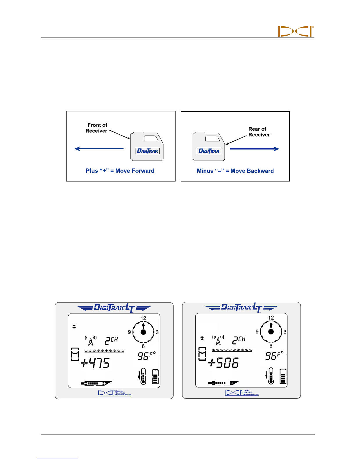
in and use the signal strength and plus/minus signs for locating. In general, the plus sign ("+") means
move the receiver forward, and the minus sign ("–") means move it backward, to find the locate point.
Using Plus/Minus (“+/–”) Indicators for Finding Locate Points
The front and rear locate points each represent a point where the sign changes from positive to negative.
It doesn’t matter if the receiver and transmitter are facing in the same direction or in opposite directions,
the "+" sign will change to a "–" sign at either of the locate points.
Anywhere along the locate line, when the receiver crosses it, the "–" sign will change to a "+" sign. The
position of the transmitter along the LL can be determined by finding the FLP or RLP.
Finding the FLP
1. Stand out in front of the drill head (facing the drill) at a distance of approximately one drill rod length.
2. Hold in the trigger and approach the FLP. The signal strength will be positive and will increase. Note
that the target appears in the top left corner of the display, and the target gets closer to the box
(locating icon) as you walk toward the FLP.
Target in Top Left Corner Target Moving Toward the Box
46 DigiTrak®
L
Operator’s Manual
T
™
Page 47
Locating
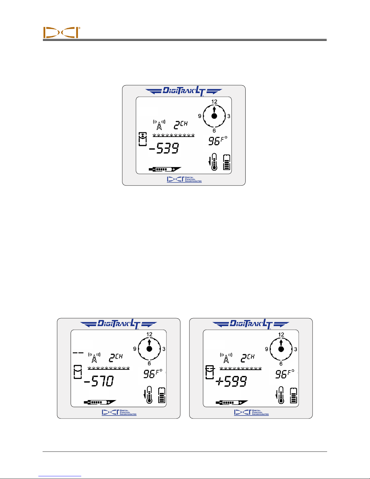
3. Continue to walk forward until the "+" sign changes to a "–". Note that the target has moved into the
box and the signal strength has increased.
Target in the Box
4. Turn the receiver 90° from the transmitter heading while holding the receiver steady and level, and
again find the point where the "+" sign changes to a "–" by moving the receiver forward or backward
as needed; the target should be in the box. This is the FLP, which is where the transmitter will end up
if it does not get a steering command. Release the trigger.
5. Mark the location directly below the display screen as the FLP.
Finding the Transmitter and the LL
1. At the FLP, while continuing to hold in the trigger, turn again to face the drill head (and drill) and walk
forward toward the last locate point.
2. Note that the signal strength is negative and the value is increasing. The LL will appear in the top left
of the display.
3. Continue to walk forward until the "–" sign changes to a "+" sign. Note that the LL is centered in the
box.
LL Moving Toward the Box Line in the Box
DigiTrak®
L
Operator’s Manual 47
T
™
Page 48
Locating
Arrow pointing to tool
head indicates the
line is in the box and
the receiver is above
the transmitter or LL.
Transmitter Pitch
Replaces
Temperature
Reading
Height-Above-Ground
Setting Replaces
Telemetry Channel
Setting
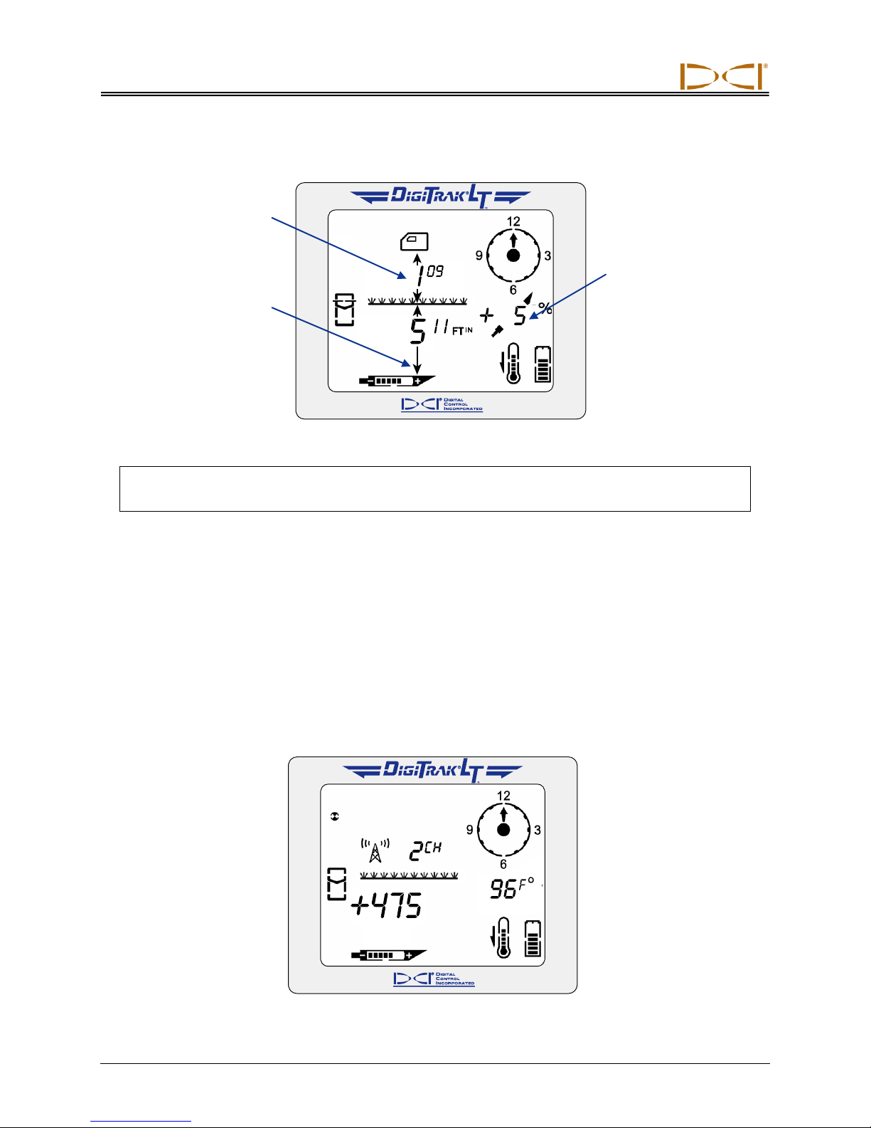
4. Release the trigger to see the depth display.
Depth Screen
NOTE: The arrow that appears below the depth measurement and that points to the transmitter
also appears on the remote display when the line is in the box.
5. Mark this location as the LL. You should now be standing above the transmitter.
Confirmation of Exact Heading and Transmitter Position
Like in the standard locating method, you can confirm the actual transmitter heading by locating the rear
locate point or RLP and then drawing a line between the RLP and FLP. That line represents the
transmitter heading. Where this line intersects the LL is the position of the transmitter.
Finding the RLP
1. While standing above the transmitter still facing the drill, hold in the trigger and continue walking
toward the drill; the signal strength will decrease and the target will appear in the top left corner of the
display.
48 DigiTrak®
Target in Top Left Corner
L
Operator’s Manual
T
™
Page 49
Locating
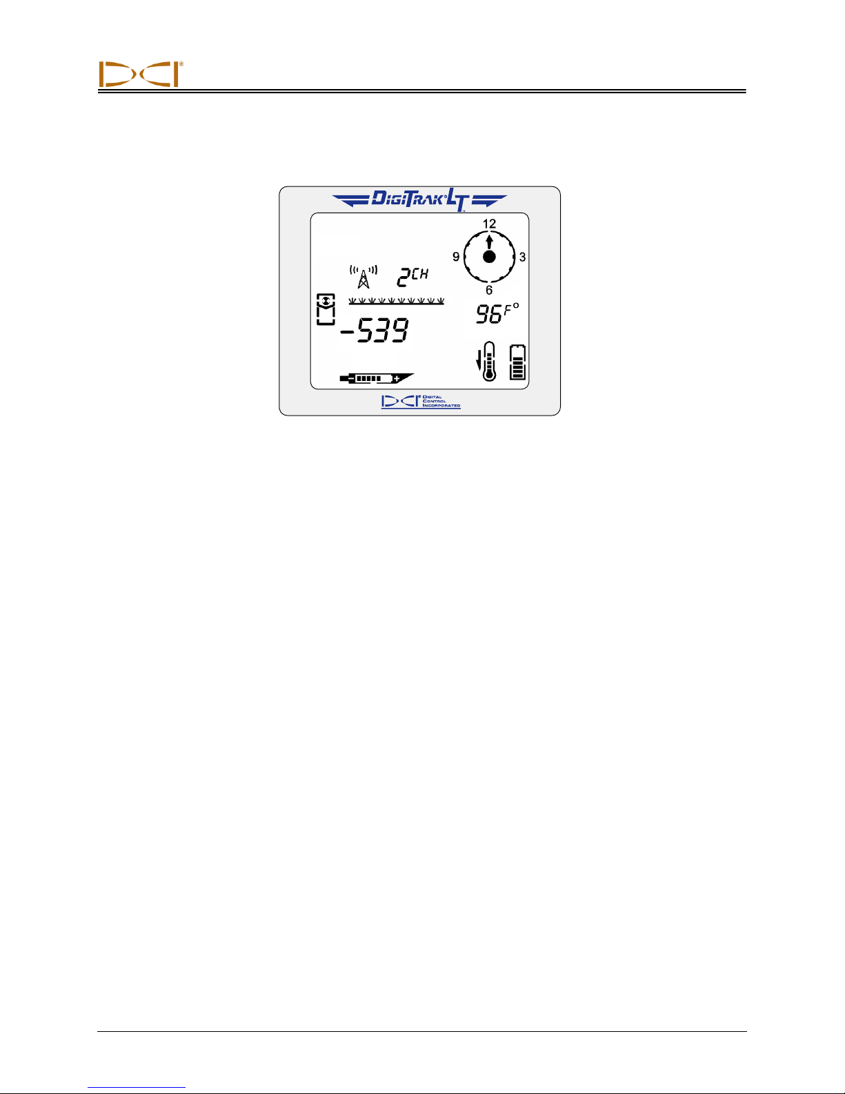
2. Walk forward until the "+" sign changes to a "–" sign. Note that the target has moved into the box.
Target in the Box
3. Turn the receiver 90° from the transmitter heading while holding the receiver steady and level, and
find the point where the "–" sign changes to a "+" by moving the receiver forward or backward as
needed; the target should be in the box. This is the RLP. Release the trigger.
4. Mark this location as the RLP.
5. Connect the RLP to the FLP by a line. This line represents the transmitter heading.
DigiTrak®
L
Operator’s Manual 49
T
™
Page 50

DIGITAL
CONTROL
INCORPORATED
19625 62nd Ave S, Suite B103
Kent Washington 98032, USA
425.251.0559 / 800.288.3610
[email protected], www.DigiTrak.com
LIMITED WARRANTY
Digital Control Incorporated ("DCI") warrants that when shipped from DCI each DCI Product will conform to DCI’s current published
specifications in existence at the time of shipment and will be free, for the warranty period (“Warranty Period”) described below, from
defects in materials and workmanship. The limited warranty described herein (“Limited Warranty”) is not transferable, shall extend only to
the first end-user (“User”) purchasing the DCI Product from either DCI or a dealer expressly authorized by DCI to sell DCI Products
(“Authorized DCI Dealer”), and is subject to the following terms, conditions and limitations:
1. A Warranty Period of twelve (12) months shall apply to the following new DCI Products: receivers/locators, remote displays, battery
chargers and rechargeable batteries, and DataLog® modules and interfaces. A Warranty Period of ninety (90) days shall apply to all
other new DCI Products, including transmitters, accessories, and software programs and modules. Unless otherwise stated by DCI,
a Warranty Period of ninety (90) days shall apply to: (a) a used DCI Product sold either by DCI or by an Authorized DCI Dealer who
has been expressly authorized by DCI to sell such used DCI Product; and (b) services provided by DCI, including testing, servicing,
and repairing an out-of-warranty DCI Product. The Warranty Period shall begin from the later of: (i) the date of shipment of the DCI
Product from DCI, or (ii) the date of shipment (or other delivery) of the DCI Product from an Authorized DCI Dealer to User.
2. DCI’s sole obligation under this Limited Warranty shall be limited to either repairing, replacing, or adjusting, at DCI’s option, a
covered DCI Product that has been determined by DCI, after reasonable inspection, to be defective during the foregoing Warranty
Period. All warranty inspections, repairs and adjustments must be performed either by DCI or by a warranty claim service authorized
in writing by DCI. All warranty claims must include proof of purchase, including proof of purchase date, identifying the DCI Product
by serial number.
3. The Limited Warranty shall only be effective if: (i) within fourteen (14) days of receipt of the DCI Product, User mails a fully
completed Product Registration Card to DCI; (ii) User makes a reasonable inspection upon first receipt of the DCI Product and
immediately notifies DCI of any apparent defect; and (iii) User complies with all of the Warranty Claim Procedures described below.
WHAT IS NOT COVERED
This Limited Warranty excludes all damage, including damage to any DCI Product, due to: failure to follow DCI’s operator’s manual and
other DCI instructions; abuse; misuse; neglect; accident; fire; flood; Acts of God; improper applications; connection to incorrect line
voltages and improper power sources; use of incorrect fuses; overheating; contact with high voltages or injurious substances; use of
batteries or other products or components not manufactured or supplied by DCI; or other events beyond the control of DCI. This Limited
Warranty does not apply to any equipment not manufactured or supplied by DCI nor, if applicable, to any damage or loss resulting from
use of any DCI Product outside the designated country of use. By accepting a DCI Product and not returning it for a refund within thirty
(30) days of purchase, User agrees to the terms of this Limited Warranty, including without limitation the Limitation of Remedies and
Liability described below, and agrees to carefully evaluate the suitability of the DCI Product for User’s intended use and to thoroughly read
and strictly follow all instructions supplied by DCI (including any updated DCI Product information which may be obtained at the above DCI
website). In no event shall this Limited Warranty cover any damage arising during shipment of the DCI Product to or from DCI.
User agrees that the following will render the above Limited Warranty void: (i) alteration, removal or tampering with any serial number,
identification, instructional, or sealing labels on the DCI Product, or (ii) any unauthorized disassembly, repair or modification of the DCI
Product. In no event shall DCI be responsible for the cost of or any damage resulting from any changes, modifications, or repairs to the
DCI Product not expressly authorized in writing by DCI, and DCI shall not be responsible for the loss of or damage to the DCI Product or
any other equipment while in the possession of any service agency not authorized by DCI.
DCI reserves the right to make changes in design and improvements upon DCI Products from time to time, and User understands that DCI
shall have no obligation to upgrade any previously manufactured DCI Product to include any such changes.
THE FOREGOING LIMITED WARRANTY IS DCI’S SOLE WARRANTY AND IS MADE IN PLACE OF ALL OTHER WARRANTIES,
EXPRESS OR IMPLIED, INCLUDING BUT NOT LIMITED TO THE IMPLIED WARRANTIES OF MERCHANTABILITY AND FITNESS
FOR A PARTICULAR PURPOSE, IMPLIED WARRANTY OF NON-INFRINGEMENT, AND ANY IMPLIED WARRANTY ARISING FROM
COURSE OF PERFORMANCE, COURSE OF DEALING, OR USAGE OF TRADE, ALL OF WHICH ARE HEREBY DISCLAIMED AND
EXCLUDED. If DCI has substantially complied with the warranty claim procedures described below, such procedures shall constitute
User’s sole and exclusive remedy for breach of the Limited Warranty.
403-1000-00-C1 Page 1 of 2
Page 51

LIMITATION OF REMEDIES AND LIABILITY
In no event shall DCI or anyone else involved in the creation, production, or delivery of the DCI Product be liable for any
damages arising out of the use or inability to use the DCI Product, including but not limited to indirect, special, incidental, or
consequential damages, or for any cover, loss of information, profit, revenue or use, based upon any claim by User for breach of
warranty, breach of contract, negligence, strict liability, or any other legal theory, even if DCI has been advised of the possibility
of such damages. In no event shall DCI’s liability exceed the amount User has paid for the DCI Product. To the extent that any
applicable law does not allow the exclusion or limitation of incidental, consequential or similar damages, the foregoing
limitations regarding such damages shall not apply.
This Limited Warranty gives you specific legal rights, and you may also have other rights which vary from state to state. This Limited
Warranty shall be governed by the laws of the State of Washington.
WARRANTY CLAIM PROCEDURES
1. If you are having problems with your DCI Product, you must first contact the Authorized DCI Dealer where it was purchased. If you
are unable to resolve the problem through your Authorized DCI Dealer, contact DCI’s Customer Service Department in Kent,
Washington, USA at the above telephone number between 6:00 a.m. and 6:00 p.m. Pacific Time and ask to speak with a customer
service representative. (The above “800” number is available for use only in the USA and Canada.) Prior to returning any DCI
Product to DCI for service, you must obtain a Return Merchandise Authorization (RMA) number. Failure to obtain an RMA may
result in delays or return to you of the DCI Product without repair.
2. After contacting a DCI customer service representative by telephone, the representative will attempt to assist you in troubleshooting
while you are using the DCI Product during actual field operations. Please have all related equipment available together with a list of
all DCI Product serial numbers. It is important that field troubleshooting be conducted because many problems do not result from a
defective DCI Product, but instead are due to either operational errors or adverse conditions occurring in the User’s drilling
environment.
3. If a DCI Product problem is confirmed as a result of field troubleshooting discussions with a DCI customer service representative,
the representative will issue an RMA number authorizing the return of the DCI Product and will provide shipping directions. You will
be responsible for all shipping costs, including any insurance. If, after receiving the DCI Product and performing diagnostic testing,
DCI determines the problem is covered by the Limited Warranty, required repairs and/or adjustments will be made, and a properly
functioning DCI Product will be promptly shipped to you. If the problem is not covered by the Limited Warranty, you will be informed
of the reason and be provided an estimate of repair costs. If you authorize DCI to service or repair the DCI Product, the work will be
promptly performed and the DCI Product will be shipped to you. You will be billed for any costs for testing, repairs and adjustments
not covered by the Limited Warranty and for shipping costs. In most cases, repairs are accomplished within 1 to 2 weeks.
4. DCI has a limited supply of loaner equipment available. If loaner equipment is required by you and is available, DCI will attempt to
ship loaner equipment to you by overnight delivery for your use while your equipment is being serviced by DCI. DCI will make
reasonable efforts to minimize your downtime on warranty claims, limited by circumstances not within DCI’s control. If DCI provides
you loaner equipment, your equipment must be received by DCI no later than the second business day after your receipt of loaner
equipment. You must return the loaner equipment by overnight delivery for receipt by DCI no later than the second business day
after your receipt of the repaired DCI Product. Any failure to meet these deadlines will result in a rental charge for use of the loaner
equipment for each extra day the return of the loaner equipment to DCI is delayed.
403-1000-00-C1 Page 2 of 2
 Loading...