

Digital Control DigiTrak Aurora AF10, DigiTrak Aurora AP8, DigiTrak Aurora AF8 Operator's Manual
Page 1
Series Display
Operator’s Manual
Panel Mounted AP8
Freestanding AF8 and AF10
www.DigiTrak.com
Page 2

DIGITALCONTRO LINCORP ORATED
403-2800-21-C, metric, printed on 12/13/2017. For software v2.0 and later.
© 2017 DigitalControl Incorporated. Allrights reserved.
Trademarks
The Aurora logo, the DCI®logo, DigiTrak®, F2, F5®, MFD®, SE®, SST®, Target Steering®, and TensiTrak®are U.S. registered
trademar ks and Ball-in-the-Box™ and F Series™ are trademarks of Digital Control Incorpor ated. Bluetooth®is a registered
trademar k of Bluetooth SIG Inc.
Patents
U.S. and foreign patents apply to the product covered by this manual. For details,please visit www.DigiTrak.com/patents.
Limited Warranty
Allproducts manufactured and soldby DigitalControl Incorporated (DCI) are subject to the terms of a Limited Warranty. A copy of the
Limited Warranty isincluded at the end of this manual; it can also be obtained by contacting DCI Customer Service, 425- 251-0559 or
800-288- 3610, or on DCI's website,www.DigiTrak.com.
Important Notice
Allstatements, technical information, and recommendations related to DCI products are based on information believed to be reliable.
However, DCI does not warrant or guarantee the accuracy or completeness of such information. Befor e using any DCI product, the
user should determine the suitability of the product for itsintended use. All statements herein refer to DCI productsas delivered by DCI
for use with horizontaldirectional drilling in the ordinary course, and do not applyto any user customizations, third party applications
developed for Aurora, third-party products, or any usage of the DCI product outside of the ordinary course. Nothing herein shall
constitute a warranty by DCI nor will anything herein be deemed to modify the terms of DCI’sexisting Limited Warranty applicable to all
DCI products.DCI may update or correct the information in this manual from time to time. You may find the most recent version of this
manual on DCI's website, www.DigiTrak.com.
Compliance Statement
This equipment complies with Part 15 of the Rules of the FCC and with Industry Canada license-exempt RSS standards and with
Australia Class License 2000 for LIPD (low interference potential devices). Operation issubject to the following two conditions: (1) this
equipment may not cause harmful interference, and (2) this equipment must accept any interference received, including interference
that may cause undesired operation. DCI isresponsible for FCC compliance in the United States: Digital Control Incorporated, 19625
62nd Ave S, Suite B103, Kent WA 98032; phone 425-251-0559 or 800-288-3610.
Changes or modifications to any DCI equipment not expressly approved and carried out by DCI willvoid the user’s Limited Warranty
and the F CC’s authorization to operate the equipment.
CE Requirements
DigiTrak receivers are classified as Class 2 radio equipment per the R&TTE Directive and may not be legal to operate or
require a user license to operate in some countries. The list of restrictions and the required declarations of conformity
are available on DCI’s website atwww.DigiTrak.com.
ii DigiTrak®Aurora®DisplayOperator's Manual
Page 3
Contact Us
DIGITALCONTRO LINCORP ORATED
United States
DCI Headquarters
Australia
China
Europe
19625 62nd Ave S, Suite B103
Kent, Washington 98032, USA
1.425.251.0559 / 1.800.288.3610
1.425.251.0702 fax
2/9 Frinton Street
Southport QLD 4215
61.7.5531.4283
61.7.5531.2617 fax
368 Xingle Road
Huacao Town
Minhang District
Shanghai 201107, P.R.C.
86.21.6432.5186
86.21.6432.5187 (传真 )
Brueckenstraße 2
97828 Marktheidenfeld
Deutschland
49.9391.810.6100
49.9391.810.6109 Fax
India
Russia
DTJ 203, DLF Tower B
Jasola District Center
New Delhi 110025
91.11.4507.0444
91.11.4507.0440 fax
Молодогвардейская ул., д.4
стр. 1, офис 5
Москва, Российская Федерация 121467
7.499.281.8177
7.499.281.8166 факс
DigiTrak®Aurora®DisplayOperator's Manual iii
Page 4

DIGITALCONTRO LINCORP ORATED
Dear Customer,
Thank you for choosing a DigiTrak guidance system. We are proud of the equipment we have been designing
and building in Washington State since 1990. We believe in providing a unique, high-quality product and
standing behind it with world-class customer service and training.
Please take the time to read this entire manual, especially the section on safety. Please also register your
equipment online at access.DigiTrak.com. Or, fill in the product registration card provided with this
equipment and either fax it to us at 253-395-2800 or mail it to DCI headquarters.
Product registration entitles you to free telephone support (in the USA and Canada), notification of product
updates, and helps us provide you with future product upgrade information.
Our Customer Service department is available 24 hours a day, 7 days a week in the U.S. to help with
problems or questions. International contact information is available in this document and on our website.
As the horizontal directional drilling industry grows, we’re keeping our eye on the future to develop equipment
that makes your job faster, easier, and safer. Visit us online any time to see what we’re up to.
We welcome your questions, comments, and ideas.
Digital Control Incorporated
Kent, Washington
2017
Watch our DigiTrak Training Videos at www.YouTube.com/DCIKent
For system component name and model information, refer to Appendix A on page 34.
iv DigiTrak®Aurora®DisplayOperator's Manual
Page 5

DIGITALCONTRO LINCORP ORATED
Table of Contents
Important Safety Instructions 1
General 1
Safety 1
Care and Maintenance 3
Touchscreen Interface 3
Cleaning 3
Heat and Sunlight 3
General 4
Introduction 5
Getting Started 6
Freestanding AF10 6
All Models 6
Installing Your Display 7
Main Menu 8
Power On 8
Applications 9
Settings 10
Device 11
Network 12
Alarms 14
Pitch History 15
Receiver 16
Peripherals 17
Update 17
Help 19
Drilling with the Home Screen 20
Telemetry Signal Strength 20
Roll Offset 21
Temperature 21
Fluid Pressure Transmitter 21
Depth Readings 22
Predicted Depth 22
Target Steering 24
Steering to the Target 24
Target Steering in Interference Areas 26
Understanding the Steering Indicator Ball 27
Classic View 27
Turning Target Steering Off 28
Working with TensiTrak 29
Setting Warning Levels 29
DigiTrak®Aurora®DisplayOperator's Manual v
Page 6
DIGITALCONTRO LINCORP ORATED
Working with the MFCB 30
Enabling the MFCB 30
Using a Cable Transmitter 31
Applying Power to the Transmitter 31
Using a Steering Tool Transmitter (SST) 31
Setting a Heading Reference 32
Appendix A: System Specifications 34
Power Requirements 34
Environmental Requirements 34
Networking Requirements 34
Storage and Shipping Requirements 34
Temperature 34
Packaging 34
STANDARD WARRANTY
Product drawings in this document contain distinctly different colors to help the reader
distinguish components. These colors are for illustration purposes only and do not represent
actual product colors.
vi DigiTrak®Aurora®DisplayOperator's Manual
Page 7
DIGITALCONTRO LINCORP ORATED
All operators must read and understand the following safety precautions and warnings and must
review this operator’s manual and the operator’s manual for their DigiTrak®guidance system
before using the Aurora display. If you have any questions about the operation of Aurora, please
contact DCI Customer Service for assistance.
Important Safety Instructions
General
The following warnings relate generally to the operation of DigiTrak®guidance systems. This is not
an exhaustive list. Please review the operator’s manual for your DigiTrak guidance system for
additional safety precautions and warnings relating to its use.
Serious injury and death can result if underground drilling equipment makes contact with an
underground utility such as a high-voltage electrical cable or a natural gas line. DigiTrak guidance
systems cannot be used to locate underground utilities.
Work slowdowns and cost overruns can occur if drilling operators do not use the drilling or
guidance equipment correctly to obtain proper performance.
Substantial property damage and liability can result if underground drilling equipment makes
contact with an underground utility.
This symbol on equipment indicates that the equipment must not be disposed of with your other
household waste. Instead, it is your responsibility to dispose of such equipment at a designated
collection point for the recycling of electrical and electronic equipment. The separate collection
and recycling of your waste equipment at the time of disposal will help conserve natural
resources and ensure it is recycled in a manner that protects human health and the environment.
For more information about where you can drop off your waste equipment for recycling, please
contact your local city office, your household waste disposal service, or the shop where you
purchased the equipment.
Safety
Aurora is for use solely with DigiTrak Horizontal Directional Drilling guidance systems. The
warnings in this section relate specifically to the operation of an Aurora display with DigiTrak
guidance systems.
The Aurora display does not eliminate the need for human judgment by a drill rig operator. Danger may arise
at the job site at any time even without an alarm or warning from the Aurora display. Drill rig operators must
maintain close attention to the drilling operation at all times.
Do not view training videos or help files on Aurora while drilling.
DCI does not warrant or guarantee the accuracy of data or information displayed or generated by Aurora. The
accuracy of such data or information may rely on the accuracy of input from third-party sources, such as drill
rigs or other equipment manufactured by third parties, GPS data, or bore plan or other data input by a user.
DCI cannot be responsible for the accuracy of such third-party input.
DigiTrak®Aurora®DisplayOperator's Manual 1
Page 8

DIGITALCONTRO LINCORP ORATED
The accuracy of data generated by a DigiTrak Guidance System may be affected by a variety of factors,
including (but not limited to) interference (passive or active) or other environmental conditions, improper use
of the DigiTrak guidance system by the end user, failure to follow instructions found in the operator’s manual
for the DigiTrak guidance system, and failure to properly calibrate the DigiTrak Guidance System. Always
perform a background noise check prior to drilling.
Aurora transmits radio signals. Accordingly, maintain a minimum distance of 20 cm between the user’s torso
and the Aurora display during operation to ensure compliance with RF exposure requirements.
Because this equipment may generate radio frequency energy, there is no guarantee that interference will not
occur at a particular location. If this equipment does interfere with radio or television reception, which can be
determined by powering the equipment off and on, try to correct the interference using one or more of the
following measures:
l Reorient or relocate the Aurora antenna.
l Increase the separation between the Aurora and affected equipment.
l Consult the dealer or DCI Customer Service for help.
In the event of electrostatic shock, the touchscreen may act as if it has been touched. No data loss will occur
but windows may open or close randomly. User intervention is required to return the screen to the previous
state.
An Aurora display is GPS-ready. Review local regulations governing the use of GPS before using any
applications that employ this technology.
Failure to properly care for and maintain your Aurora display may result in malfunction or inoperability of the
unit. If your Aurora malfunctions or ceases to operate for any reason, stop drilling immediately and contact
DCI Customer Service.
An Aurora display contains no user serviceable parts. Contact your local HDD dealer or DCI customer
service if you believe service is required.
2 DigiTrak®Aurora®DisplayOperator's Manual
Page 9

DIGITALCONTRO LINCORP ORATED
Care and Maintenance
Touchscreen Interface
Avoid operating Aurora while wearing gloves not specifically designed for use with touchscreens, as the
response will be poor and foreign material on the gloves may damage the touchscreen. Use the soft pad of
your fingertip to tap the display, or use gloves with a touchscreen-compatible fingertip. Never use a fingernail
or foreign object.
Cleaning
Use only a glass cleaner that is specifically tested to not harm the protective coatings on touchscreen glass.
Use the power button to lock the screen for cleaning (see Power On, page 8).
A non-abrasive soap and water mixture is suitable for both the display and case.
Wipe the screen gently with a microfiber or soft cotton cloth, as hard rubbing may remove or damage the antireflective coating. Avoid salt water, which is abrasive.
Do not use household or commercial window cleaning products that include chemicals such as ammonia,
alcohol, or any acidic liquid. These cleaners can contain microscopic abrasive granules that will damage the
anti-reflective film and may cause the display to spot.
Use all provided connector covers when connectors are not in use. Ensure connectors are free of debris
before making connections.
The Aurora is IP66-rated to be resistant to water jets with pressure up to 1.0 bar at a distance of 3 m. Avoid
using pressure washers or steam cleaners that exceed this level.
Heat and Sunlight
It is normal for the display to get warm. The housing functions as a cooling surface that transfers heat from
the inside. In hot environments, you can help your Aurora stay cool by providing shade and/or lowering the
touchscreen brightness.
In extreme heat and direct sunlight conditions, the maximum internal operating temperature of the Aurora unit
may be exceeded. One of the first symptoms of overheating is an unresponsive touchscreen. To restore
functionality in this case, shade the display from direct sunlight, turn down the screen brightness, and allow it
to cool. If possible, turn the display completely off using the power button or by removing power from the
display. After sufficient cooling time, full functionality will return.
If Aurora senses it is overheating, it will slow processing tasks to minimize heat and protect internal
components. If overheating continues, it will shut down before any damage can occur. If this happens, stop
drilling immediately, keep the Aurora off and in shade, and allow fifteen minutes for it to cool before restarting.
If excessive heat causes the touch function to become unresponsive, you can still use a USB mouse to
make selections, such as accessing the Settings window to lower the screen brightness.
DigiTrak®Aurora®DisplayOperator's Manual 3
Page 10

DIGITALCONTRO LINCORP ORATED
General
Turn off the display when not in use.
Store the display in its case, away from extremes of heat, cold, and moisture. Test to confirm proper
operation prior to use.
Inspect the display daily and contact DCI if you see any damage or problems. Do not disassemble or attempt
to repair.
4 DigiTrak®Aurora®DisplayOperator's Manual
Page 11
Introduction
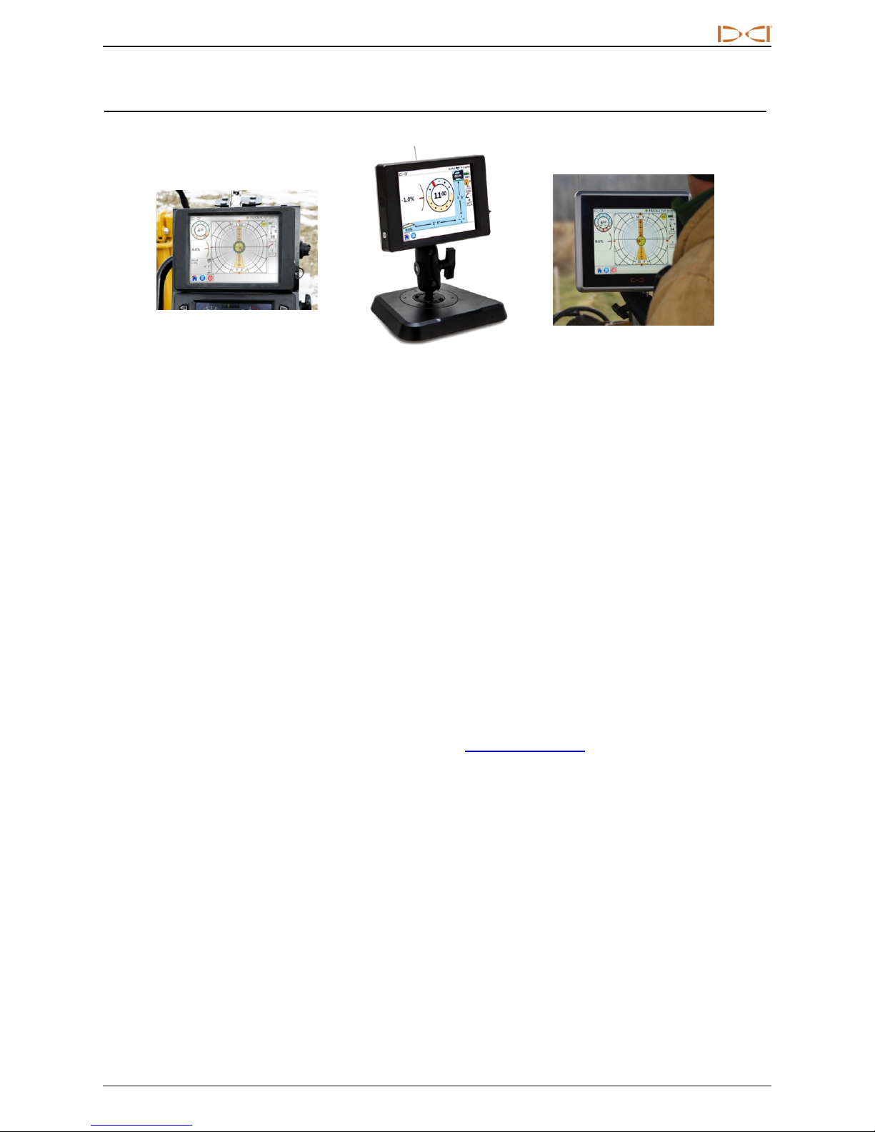
Panel Mounted AP8 Freestanding AF8 Freestanding AF10
DIGITALCONTRO LINCORP ORATED
DigiTrak Aurora Displays
The Aurora®DigiTrak®Series Display is a multifunction touchscreen device that is compatible with SE®,
FSeries™, and Falcon DigiTrak guidance receivers. A receiver is used during horizontal directional drilling
operations to locate and track a transmitter installed in the drill head. Aurora provides the drill rig operator
information from the receiver about the depth, orientation, and status of the transmitter. Aurora’s multitasking ability allows it to (for example) simultaneously track and graph fluid pressure and monitor Target
Steering®.
Aurora is powered through the drill rig’s DC power supply. The supplied external 33 cm telemetry antenna
enhances signal reception up to 550 m with line of sight to the receiver (dependent on local regulatory
constraints). An optional antenna is available to increase reception for even longer bores.
A complete system consists of an Aurora display, handheld receiver (locator), transmitter, power cable,
battery charger, and battery packs for powering the receiver. Depending on how you purchased your Aurora,
you may or may not have received all of these components.
This manual discusses only operation of the Aurora display. For additional information on the other
components of a DigiTrak guidance system, as well as helpful information on drilling and locating, please see
the corresponding DigiTrak Operator’s Manual, available at www.DigiTrak.com.
This manual assumes the use of a Falcon F5®receiver. When using the Aurora display with other DigiTrak
receivers, small differences in screen elements or behavior will exist, but the primary functionality remains
the same, within the capabilities of your receiver.
DigiTrak®Aurora®DisplayOperator's Manual 5
Page 12
DIGITALCONTRO LINCORP ORATED
Getting Started
Following are the basic steps for setting up your Aurora display for drilling. For complete details on the safe
setup, operation, and features of your Aurora, please review the rest of this manual.
Keep the separate Quick Start Guide (QSG) that came with your Aurora with you while you drill. The QSG is
also available on your Aurora through the Help menu.
Remember to register your Aurora at access.DigiTrak.com so you can stay informed about important
updates to your display and apps.
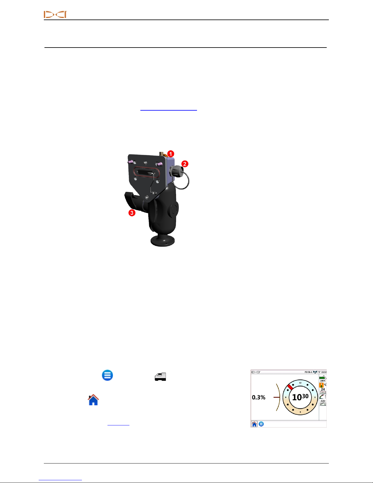
Freestanding AF10
1. Thumb screw
2. Power
3. Locking knob
AF10 2-inch ball mount
1. Install the docking station in a solid location and tighten the locking knob firmly.
2. Connect the round keyed connector on the power cable to the docking station and the other end to a
12–24 VDC accessory port.
3. Connect your Aurora to the docking station using the thumb screw on the back.
Continue below.
All Models
1. Connect the telemetry antenna.
2. Connect Aurora to a power source; it displays the Home screen.
3.
Tap Main Menu , then Receiver to select your type of receiver,
telemetry channel to match that of the receiver, and region.
4.
Tap Home to return to the Home screen. If the receiver is receiving
data from a transmitter, that data will now display on the Aurora.
For more information on Settings, see page 10.
6 DigiTrak®Aurora®DisplayOperator's Manual
Page 13
DIGITALCONTRO LINCORP ORATED
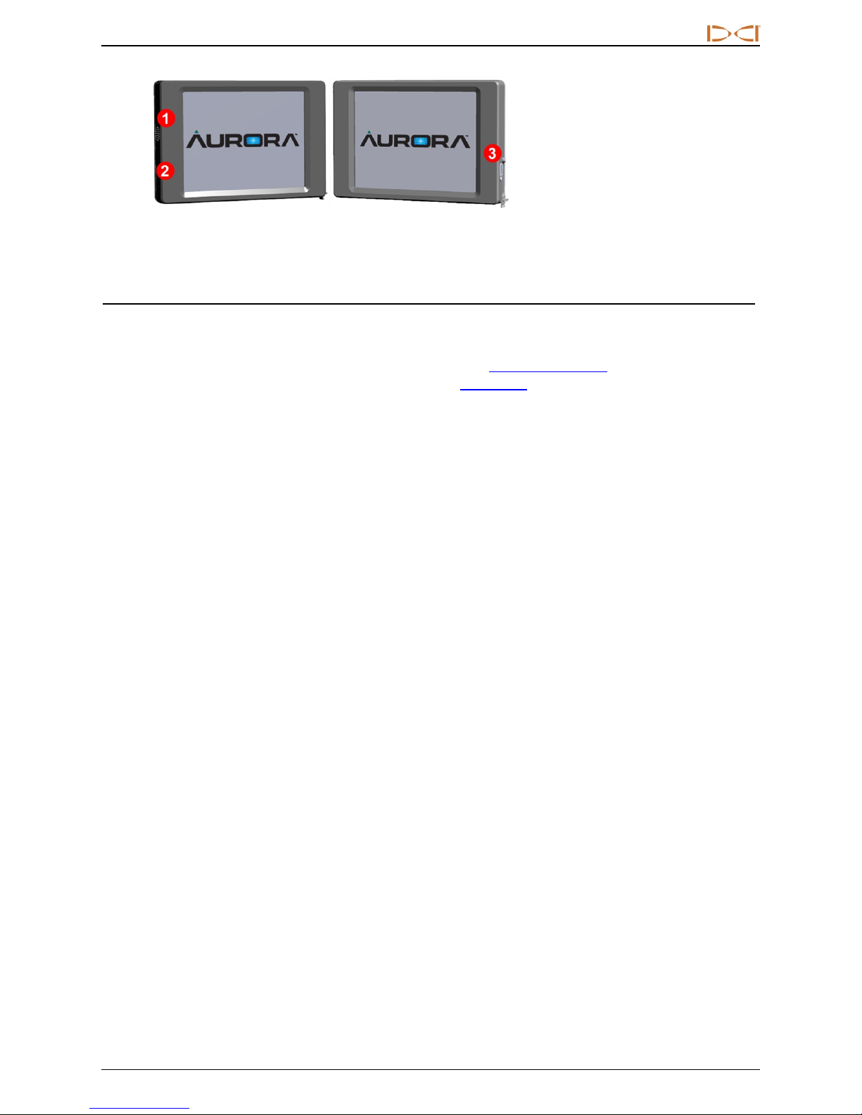
1. Speaker
2. Power/screen lock b utton
3. USB port
Aurora Panel Mounted AP8
Installing Your Display
An 8-inch panel mounted Aurora (model AP8) should be installed by your DigiTrak dealer. To install the AP8
yourself, refer to the MFD/Aurora Installation Guide, available at www.DigiTrak.com. After your panel
mounted Aurora is installed, continue with the next section, Main Menu.
For installation of the freestanding model AF10, please refer to the separate Installation Guide included with
your display.
For the freestanding model AF8, simply find a suitable location for the magnetic base to attach to and
connect the power/data wire and antenna.
DigiTrak®Aurora®DisplayOperator's Manual 7
Page 14
DIGITALCONTRO LINCORP ORATED
Main Menu
Power On
Aurora automatically turns on and displays the Home screen when it receives power.
To temporarily lock the screen so you can wipe it clean without making selections,
press and release the power button on the back. A padlock displays beside the DCI logo
in the upper left of the screen to indicate the screen is locked. Press and release the
power button again to unlock the screen.
To put the Aurora into a low-power state with the screen off and processor halted, hold the power button in for
approximately two seconds. Press and release the power button again to resume.
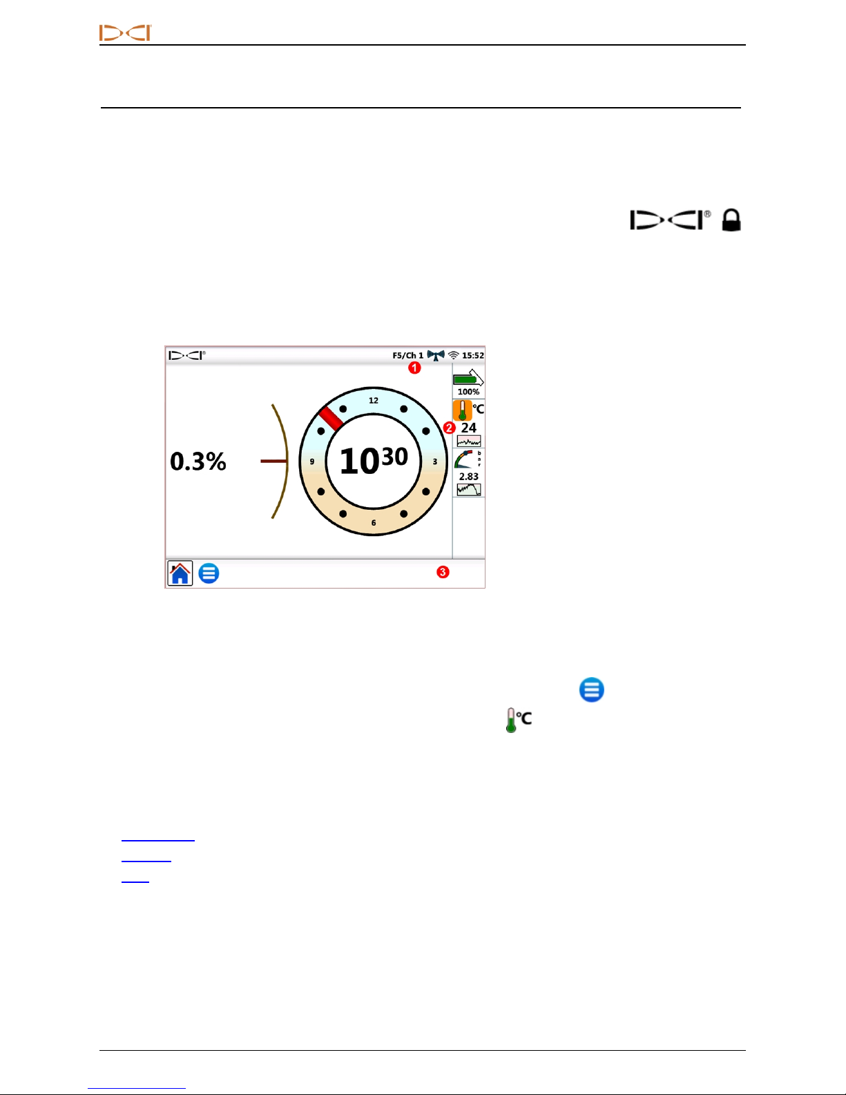
1. Telemetry channel
2. Transmitter temperature
3. Taskbar
Home Screen
The Aurora touchscreen features a taskbar at the bottom and shortcuts directly to key features. For example,
to change the telemetry channel, simply tap and hold the telemetry channel label at the top of the screen
(here Ch 1) and Aurora opens the appropriate Settings window in the Main Menu . Similarly, to view
temperature alarms, tap and hold on the transmitter temperature icon .
Use the soft pad of your fingertip to tap the display, or use gloves with a touchscreen-compatible fingertip.
Never use a fingernail or foreign object.
The main menu is divided into three tabs:
l Applications (next section)
l Settings (page 10)
l Help (page 19)
8 DigiTrak®Aurora®DisplayOperator's Manual
Page 15
DIGITALCONTRO LINCORP ORATED
Applications
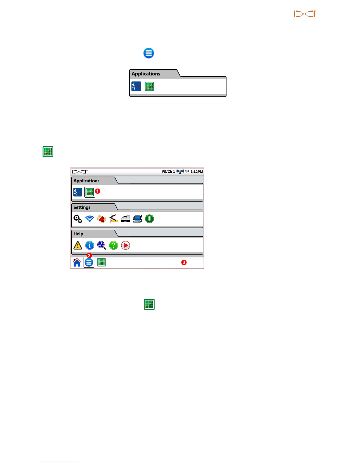
From the Home screen, tap Main Menu once. Application icons appear in the top tab.
Main Menu, Applications Tab
Notice how the Main Menu icon in the taskbar below now has a frame around it. The frame shows which
application or screen is currently displayed.
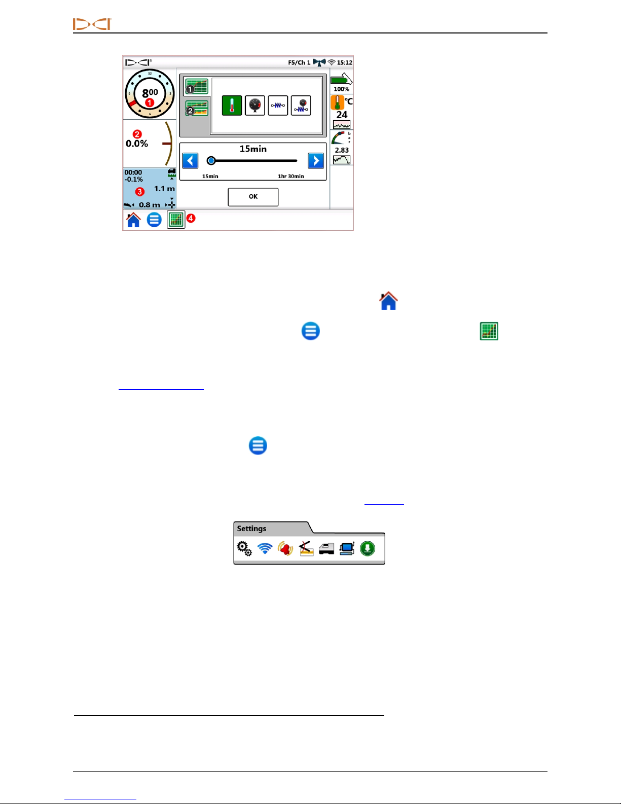
To start an application, tap the icon to place it in the taskbar. For example, tap the pre-installed Strip Chart
application icon.
1. Strip Chart icon; frame
indicates applicat ion is
loaded
2. Currently displayed windo w
is framed
3. Taskbar
Main Menu with Strip Chart Application Loaded
Aurora frames the Strip Chart icon in the main menu to indicate the application is now loaded and also
places it in the taskbar. Tap Strip Chart in the taskbar to open the application. Drilling information from
the Home screen such as transmitter roll and pitch, and even predicted depth, minimizes to the left side of
the screen as the Strip Chart setup screen appears.
DigiTrak®Aurora®DisplayOperator's Manual 9
Page 16
DIGITALCONTRO LINCORP ORATED
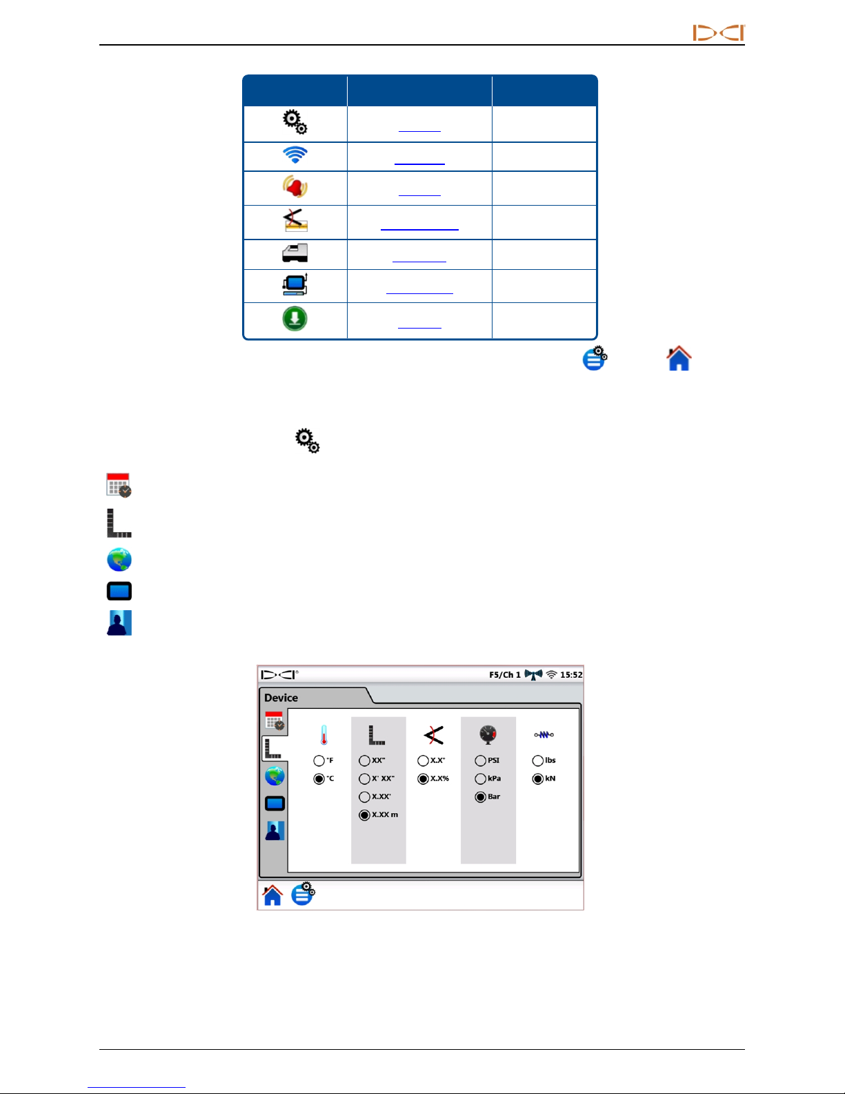
1. Roll remains visible
2. Pitch remains visible
3. Predicted dept h remains
visible
4. A frame in dicates Strip Chart
is the currently displayed
window
Strip Chart Setup Window
Strip Chart monitors and graphs fluid pressure1, temperature, and pullback tension2data over time.
To leave Strip Chart running and return to the Home screen, tap Home .
To close the Strip Chart application, tap Main Menu and then the framed Strip Chart icon on the
Applications tab. The icon becomes unframed in the apps list and is removed from the taskbar.
For details on using this or other applications, view the app sheet (AS) available in the Aurora documentation
section at www.DigiTrak.com.
Settings
From the Home screen, tap Main Menu once. Settings icons appear in the middle tab. All system setup
begins here.
Aurora requires a minimal amount of configuration to work with your particular DigiTrak receiver (locator). At
minimum, set the receiver type, telemetry channel, and region (see Receiver on page 16).
Main Menu, Settings Tab
1
Requires a fluid pressure transmitter (FPT).
2
Requires TensiTrak®pullbackand pr essure monitoring system.
10 DigiTrak®Aurora®DisplayOperator's Manual
Page 17
DIGITALCONTRO LINCORP ORATED
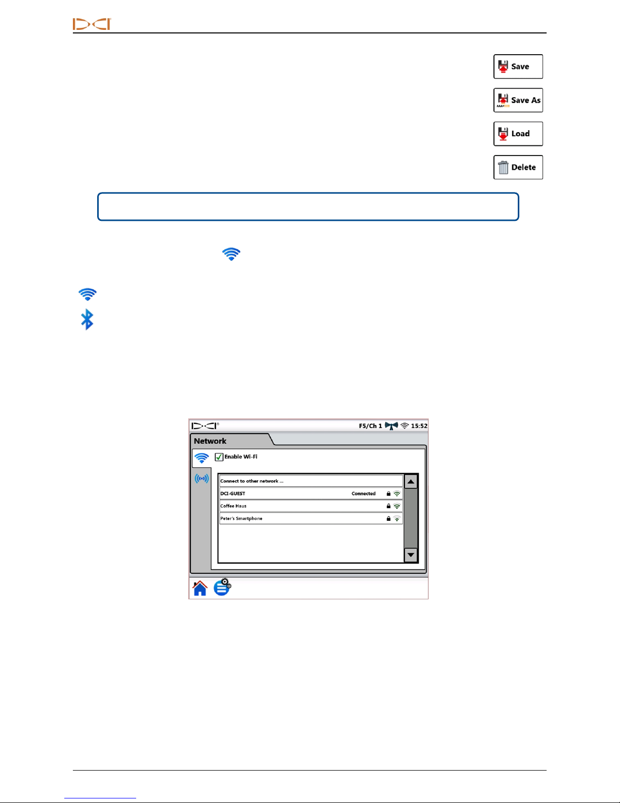
Icon Operation Page
Device 11
Network 12
Alarms 14
Pitch History 15
Receiver 16
Peripherals 17
Update 17
To exit each Settings window described in the following sections, tap Main Menu or Home in the
Taskbar.
Device
On the Settings tab, tap Device and select from the tabs on the left to set the following:
Date, time, and time zone
Units: temperature, distance, pitch angle, fluid pressure, and pull force (shown below)
Language
Screen brightness and speaker volume
Profiles
DigiTrak®Aurora®DisplayOperator's Manual 11
Settings, Device – Units
Page 18
DIGITALCONTRO LINCORP ORATED
Once you have your Aurora set just the way you like it, use Profiles to save your own personal
profile. Or, set different profiles for typical drilling jobs. Names may not contain the following
special characters: " < > , : * / \ _ - ? |.
Aurora has preset profiles for each of its onboard languages; select your language profile to
quickly set Aurora for your region, language, and units of measure. Note that selecting one of
these presets will also return alarm settings to default values.
Menu shortcut Tap and hold the TIME (15:52 above) on the Home screen.
Network
On the Settings tab, tap Network and select from the tabs on the left to enable and connect with the
following:
Wi-Fi
Bluetooth
Wi-Fi
Use Wi-Fi to download updates and new applications.
To turn Wi-Fi on, select Enable Wi-Fi.
Choose a listed Wi-Fi network from the table and follow on-screen prompts as necessary to connect. Aurora
remembers passwords for networks it has connected to previously.
To connect to a known network that is not publically broadcast, tap Connect to other network… and follow
the onscreen prompts.
12 DigiTrak®Aurora®DisplayOperator's Manual
Network Settings – Wi-Fi
Page 19
DIGITALCONTRO LINCORP ORATED
When Aurora powers on, it will not automatically reestablish previous Wi-Fi connections. To reconnect,
select Enable Wi-Fi and choose a network. To disconnect, choose a Connected network, then tap OK. To
turn Wi-Fi completely off, clear the Enable Wi-Fi check box.
Aurora is compatible with the mobile "hot spot" feature provided by many smartphones. If you are unsure if
this feature is available on your phone, how to use it, or what additional cost its use may incur, contact your
mobile phone service provider.
Aurora Wi-Fi is not compatible with public networks that require an “I Agree” terms of service
acknowledgement typically made in a web browser (known as a captive portal). Compatible networks must
be open or only require a password.
Bluetooth
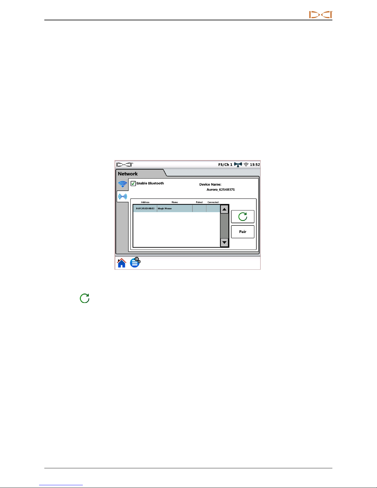
Use Bluetooth to connect a wireless mouse or similar input device.
To turn Bluetooth on, select Enable Bluetooth.
Network Settings – Bluetooth
Tap Refresh to search for available Bluetooth Human Interface Device (HID) devices.
To connect with a device, select it from the table of compatible interface devices, then tap Pair. If the device
requests a passcode, consult your device’s user manual, or try 0000 or 1234. Aurora remembers passcodes
for devices it has connected to previously.
When Aurora powers on, it will automatically attempt to reestablish Bluetooth connections that were enabled
the last time it was on.
To disconnect a Bluetooth device, select it from the table and tap Forget on the pop-up window (this will
require re-pairing to reconnect later). To turn Bluetooth completely off, clear the Enable Bluetooth check
box.
DigiTrak®Aurora®DisplayOperator's Manual 13
Page 20
DIGITALCONTRO LINCORP ORATED
Alarms
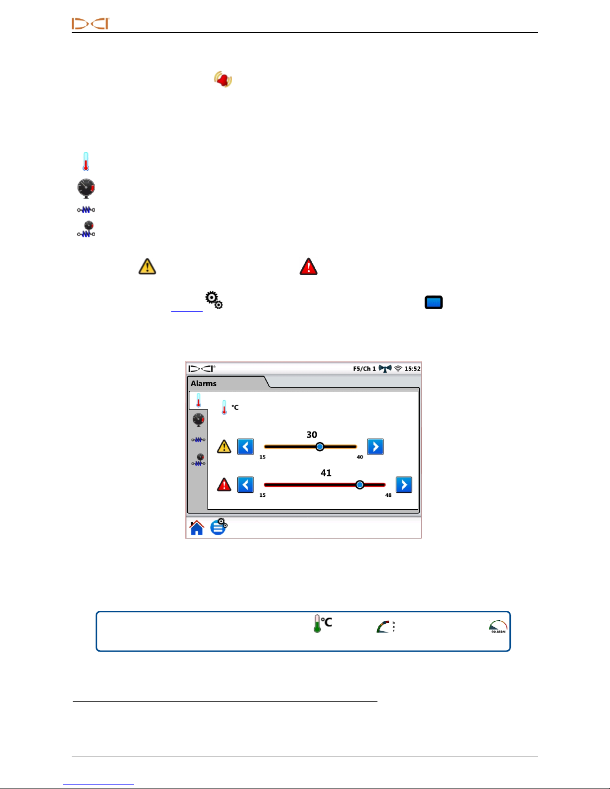
On the Settings tab, tap Alarms and select from the tabs on the left to set warning and critical levels for
temperature, fluid pressure, and pullback tension alarms. Excessive temperature, pressure, or tension
typically indicates a drilling problem that should be resolved immediately to avoid damage to equipment
and/or infrastructure. These settings will activate visual and audible warnings if the levels you set are
reached.
Transmitter temperature (shown below)
Transmitter fluid pressure
TensiTrak®Pullback tension
TensiTrak Pullback fluid pressure
1
2
2
Warning levels are marked yellow, critical levels are marked red. Aurora comes preset with
suggested alarm settings. Tap the blue arrow buttons or drag the slider control to change alarm settings. Set
speaker volume on the Device tab (see page 11) using the screen and volume icon.
Temperature alarms have maximum warning (yellow) and critical (red) levels of 40° C and 48° C,
respectively.
Pressure and tension alarms have maximum warning and critical levels of 17.2 bar or 445 kN, respectively.
Readings exceeding the maximum value will display on the Home screen as +OL (Overload).
Menu shortcut
Tap and hold the temperature , pressure , or TensiTrak tension
readings on the Home screen.
1
Requires a fluid pressure transmitter (FPT).
2
Requires TensiTrak pullbackand pressure monitoring system.
14 DigiTrak®Aurora®DisplayOperator's Manual
Alarm Settings
Page 21
DIGITALCONTRO LINCORP ORATED
Pitch History
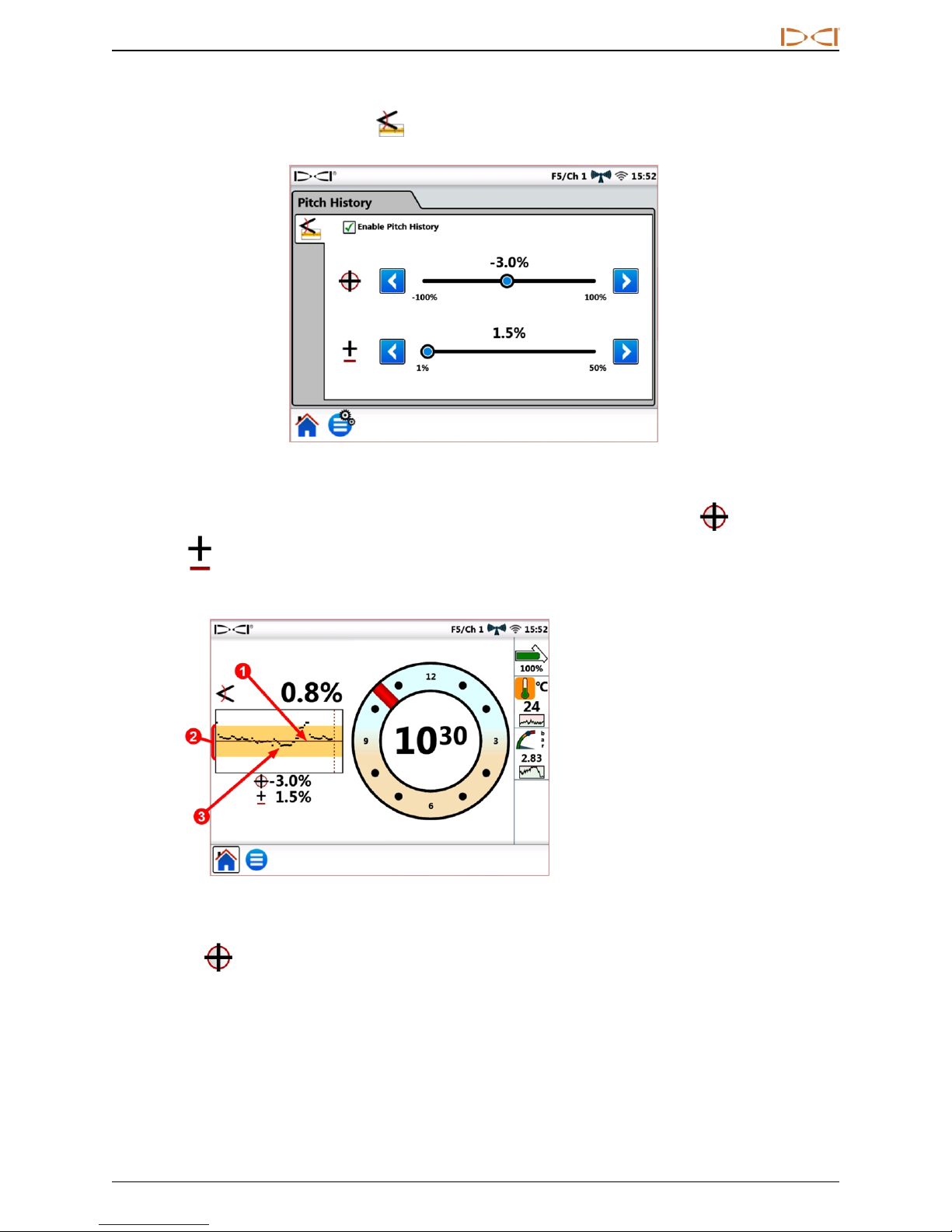
On the Settings tab, tap Pitch History , then select Enable Pitch History.
Pitch History Settings
Tap the blue arrow buttons or drag the slider control to adjust the values for Target Pitch and Pitch
Tolerance up or down. When you return to the Home screen, you will see a pitch history graph has
replaced the regular pitch indicator.
1. Target pitch
2. Pitch tolerance
3. Pitch readings
Home Screen With Pitch History Graph
Target Pitch is the pitch at which you want to drill. This is represented by the horizontal line in the
center of the graph. Keep the black plot line near the center to maintain the target pitch, shown here at -3.0%.
Target pitch is adjustable in 0.1% increments. Due to the normal underground drilling motion of the drill head,
it is normal for the plot line to continually range above and below the target pitch line as shown. Make pitch
corrections based on your visual analysis of the entire graph, not just the latest single data point. The graph
displays up to 90 seconds of pitch history, depending on model of receiver and transmitter and the current
display mode.
DigiTrak®Aurora®DisplayOperator's Manual 15
Page 22
DIGITALCONTRO LINCORP ORATED
Pitch Tolerance is the amount of deviation from the target pitch that you want to define as acceptable.
This is represented by the yellow band above and below the red target pitch line on the graph. Stay within the
yellow band to remain within the defined tolerance, shown here at ±1.5%. The minimum tolerance is 1.0%,
adjustable in 0.1% increments.
Menu shortcut
Tap and hold the pitch value on the Home screen to open the pitch history
settings tab.
The Pitch History function and its settings will remain in effect even after a power cycle. To turn Pitch
History off, return to the Pitch History tab (see beginning of this section) and clear the Enable Pitch
History check box.
Receiver
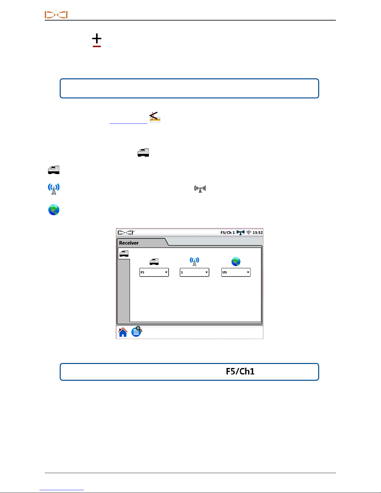
On the Settings tab, tap Receiver to set the following:
Receiver model: Select your model of receiver.
Telemetry channel: Choose the channel that minimizes interference; this will change from job site to job
site. More bars in the telemetry signal strength icon means a stronger reception. The telemetry
channel settings on Aurora and your receiver must match.
Region: Select the region of operation; your receiver must be factory-set for use in the same region.
Menu shortcut
16 DigiTrak®Aurora®DisplayOperator's Manual
Tap and hold the receiver/telemetry label on the Home screen.
Receiver Settings
Page 23
DIGITALCONTRO LINCORP ORATED
Peripherals
On the Settings tab, tap Peripherals to set the following:
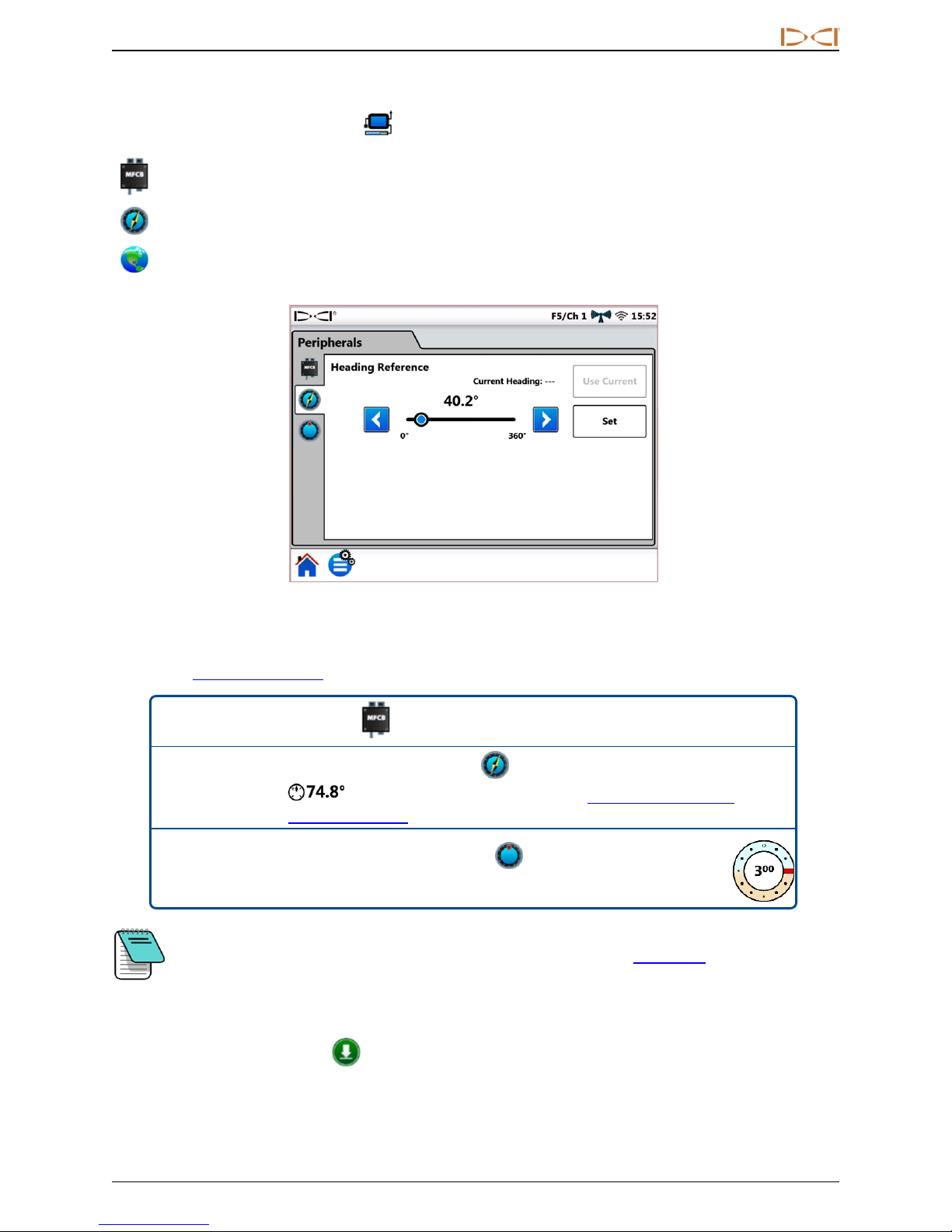
Enable or disable a Multi-Function Cable Box (MFCB) used for cable and SST®steering tool transmitters
Set SST heading reference (shown below)
Set cable transmitter roll offset
Peripherals Settings
For detailed information on using the MFCB or SST transmitter, see the appropriate operator’s manual,
available at www.DigiTrak.com.
Menu shortcut
For MFCB , tap and hold MFCB in the Status bar.
For SST Heading Reference , tap and hold the heading reference
Menu shortcut
(example) on the Home screen (see Using a Steering Tool
Transmitter (SST) on page 31).
Menu shortcut
For cable transmitter roll offset , tap and hold the roll indicator
on the Home screen.
This roll offset tab is for a cable transmitter only; when roll offset is enabled on the receiver for
a standard transmitter, it will display on Aurora automatically. See Roll Offset on page 21.
Update
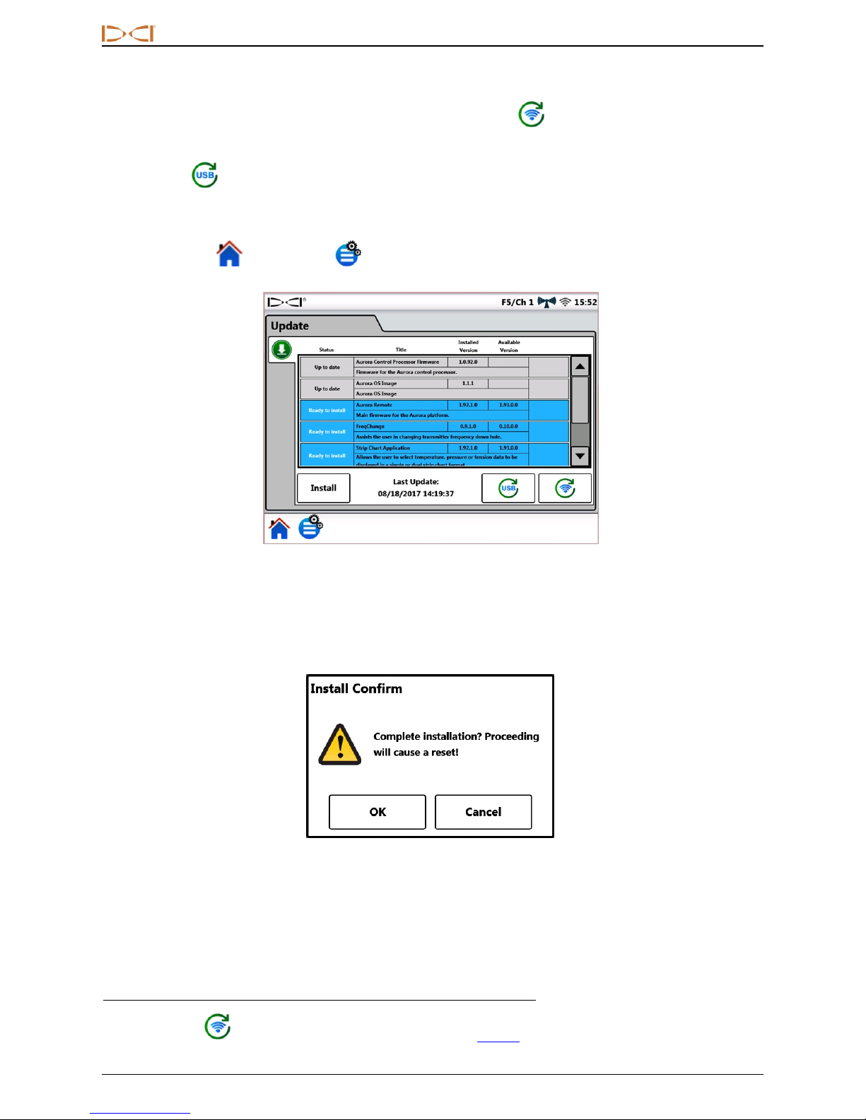
On the Settings tab, tap Update to view and download software updates to your system and
applications. Updated applications are shaded grey.
DigiTrak®Aurora®DisplayOperator's Manual 17
Page 24
DIGITALCONTRO LINCORP ORATED
To Update Your Aurora
1
To check for updates over a wireless network, tap Network Refresh
.
If a DCI representative has provided updates on a USB flash drive, insert the drive in the USB port and tap
USB Refresh to view available updates.
After Aurora searches the flash drive or remote location, it displays available updates shaded in blue. To
install all available updates, tap Install (updates cannot be selected or installed individually). To cancel the
update, tap Home or Main Menu to exit.
Update Screen – Updates Available
Aurora displays a final confirmation message. Note that the mention of a “reset” does not mean the Aurora
will reset to factory defaults, only that it will restart after installation of the updates. Tap OK to install the
update(s), or Cancel to discontinue.
Update Confirmation Screen
When the system returns to the Home screen, updating is complete.
1
Network Refresh requires a wireless connection to the Internet; see Network on page 12.
18 DigiTrak®Aurora®DisplayOperator's Manual
Page 25
DIGITALCONTRO LINCORP ORATED
Do not view training videos or help files on Aurora while drilling.
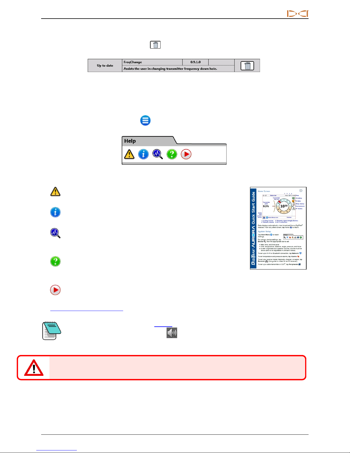
To Delete an Application
To delete an existing application, tap Delete in the appropriate row.
Application with Delete Icon
Help
From the Home screen, tap Main Menu once. Help icons appear in the bottom tab.
Main Menu, Help Tab
Safety Warnings provides important information on the cautions and
responsibilities associated with horizontal directional drilling.
Information provides detailed version information on the display's software
and firmware, as well as contact information for DCI Customer Service.
Power On Self-Tests describes tests Aurora completed when powering up.
This is useful for troubleshooting a particular component that may not be properly
connected, powered on, or enabled.
Help displays an onscreen version of the Quick Start Guide (QSG) that was
included with your Aurora. The QSG provides the basic information you need to
know about operating your Aurora.
Instructional Videos lets you watch tutorials on topics such as using TensiTrak, off-track locating,
and setting up an F5 system. These videos are also available on DCI’s YouTube channel at
www.YouTube.com/DCIKent. All telemetry is disabled while the video player is running.
If the master volume setting (see Device tab on page 11) is zero, all video volume will be
muted, regardless of the video volume slider setting.
DigiTrak®Aurora®DisplayOperator's Manual 19
Page 26
DIGITALCONTRO LINCORP ORATED
Drilling with the Home Screen
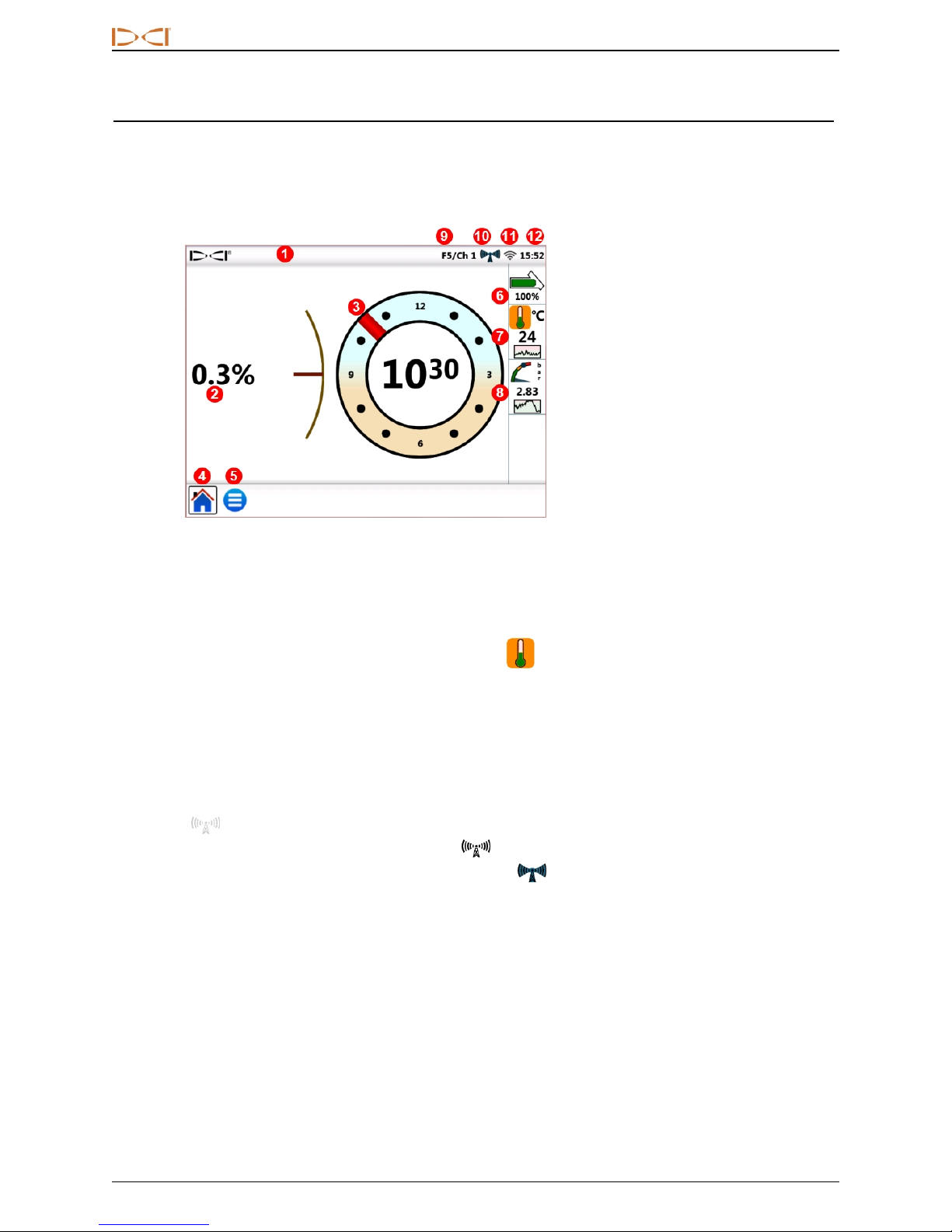
The Home screen appears automatically when Aurora powers on. It shows all the information needed for
drilling, such as transmitter pitch and roll, telemetry channel, and Target Steering data (when active).
1. Status bar
2. Transmitter (Tx) pitch
3. Tx roll
4. Home icon (shown active)
5. Main Menu icon
6. Tx battery
7. Tx temp. and temp. history
8. Fluid pressure and FP history
9. Guidance receiver / Telemetry
channel
10. Telemetry sig nal strength
11. Wi-Fi connection
12. Time
Home Screen – Locating
Data displays on the Home screen as soon as the guidance receiver, such as the F5, receives data from a
transmitter.
This sample screen also shows a high temperature caution for the drill operator. Pressure data only
displays when drilling with a fluid pressure transmitter (FPT).
Telemetry Signal Strength
The number of bars in the telemetry signal strength icon indicates the strength of signal reception from the
receiver. If the receiver is far away from the Aurora, fewer signal bars may display on the icon.
A grey icon indicates no reception from a receiver, and all transmitter information will disappear (a cable
transmitter will only lose depth). A steady black icon indicates Aurora is connected to a receiver that is
not sending data. A flashing blue background behind the icon indicates Aurora is receiving new data
from the receiver.
If Aurora is not showing telemetry data, check the following:
l Does the transmitter have batteries correctly installed?
l Has the transmitter gone to sleep due to inactivity?
l Is the receiver showing transmitter data?
l Is the receiver set to the correct transmitter and frequency?
l Are the receiver and Aurora set to the same telemetry channel?
l Verify the region setting matches that of the receiver
20 DigiTrak®Aurora®DisplayOperator's Manual
Page 27
DIGITALCONTRO LINCORP ORATED
Roll Offset
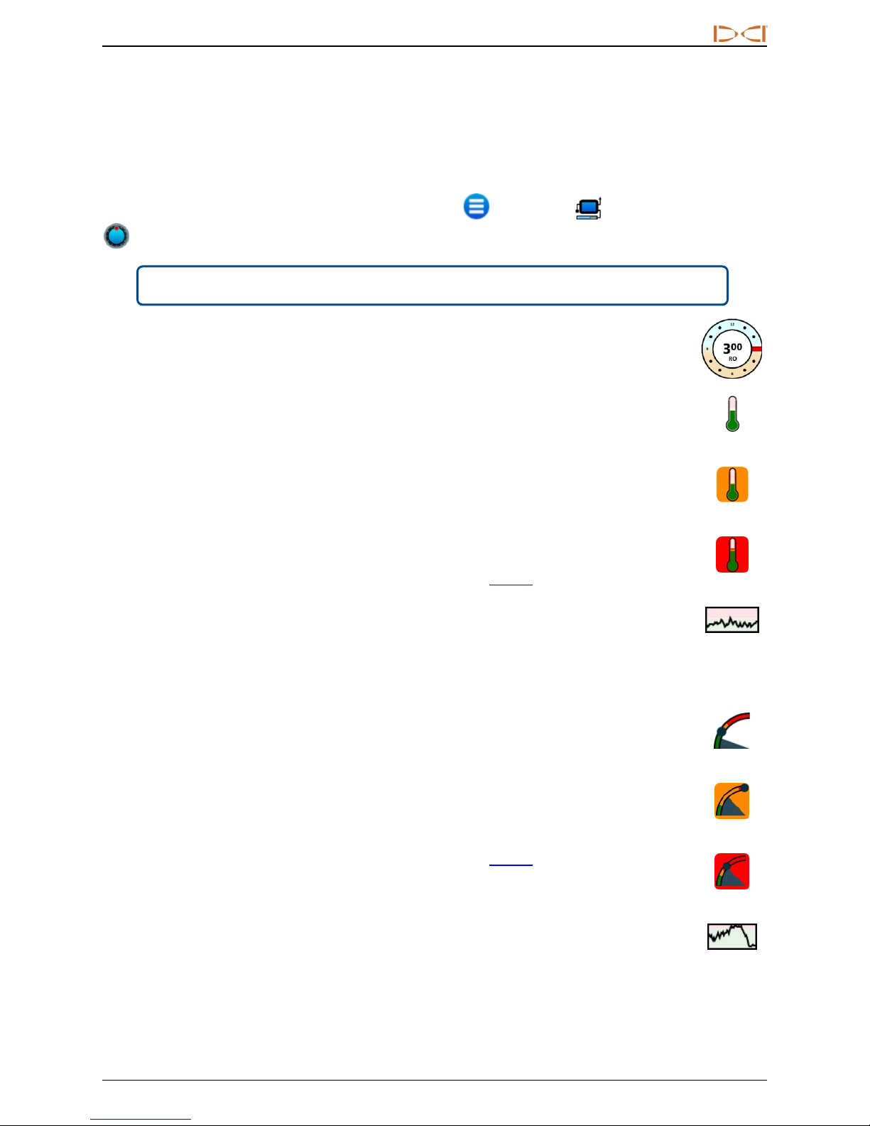
Roll offset (RO) is an electronic compensation to match the transmitter’s 12 o’clock position to the drill
head’s 12 o’clock position.
Roll offset enabled on the receiver for a standard transmitter will display on Aurora automatically.
To enable roll offset for a cable transmitter, tap Main Menu , Peripherals , and then the Roll Offset
tab.
Menu shortcut Tap and hold the roll indicator.
The letters RO on Aurora's roll indicator indicate when it is compensating for roll offset.
Temperature
All DigiTrak transmitters, including TensiTrak®, are equipped with an internal digital thermometer.
Drill head temperatures typically range from 18 to 40° C during drilling. The temperature icon on the
Home screen will flash orange slowly when the temperature reaches the warning level and flash
red quickly when it reaches the critical level. These warnings are accompanied by audible beeps.
Suspend drilling when drill head temperature exceeds 48° C to permit cooling.
Normal
Because the digital thermometer is inside the transmitter, temperature increases due to external
drilling conditions will take time to transfer to the transmitter and then the thermometer. Resolve
increases in temperature quickly to avoid irreversible damage.
Warning and critical values are user-defined as specified on the Alarms screen (see page 14).
The Temperature History graph below the temperature value shows a graph of the last four
minutes of temperature readings. Use this history to determine if temperature is trending up or
down.
Fluid Pressure Transmitter
Using a fluid pressure transmitter (FPT) or TensiTrak will show instantaneous fluid pressure on the
right side of the screen. The pressure icon on the Home screen will flash yellow slowly when the
pressure reaches the warning level and flash red quickly when it reaches the critical level. These
warnings are accompanied by audible beeps. A blue ball on the gauge marks the maximum
recorded pressure; it resets when Aurora restarts.
Readings exceeding the maximum value of 17.2 bar will display as +OL.
Warning and critical values are user-defined as specified on the Alarms screen (see page 14).
The Fluid Pressure History graph below the pressure value shows a graph of the last four minutes
of fluid pressure readings. Use this history to determine if pressure is trending up or down.
Warning
Critical
History
Normal
Warning
Critical
If you are not using an FPT or TensiTrak transmitter, pressure data will not display.
DigiTrak®Aurora®DisplayOperator's Manual 21
History
Page 28
DIGITALCONTRO LINCORP ORATED
Depth Readings
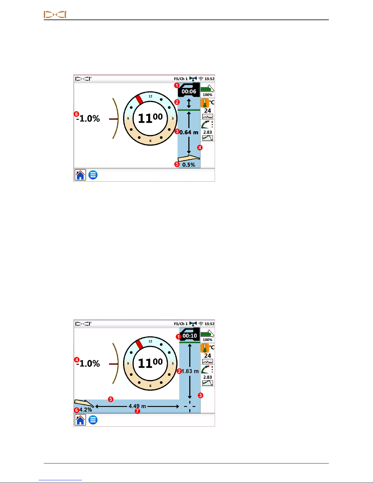
When the receiver takes a depth reading at the locate line (LL), Aurora adds the blue Depth Bar, which
provides transmitter depth and pitch information beside the roll indicator:
1. Depth timer
2. HAG on
3. Depth at time of reading
4. Depth bar
5. Pitch at time of read ing
6. Current pitch
Home Screen – Depth Reading
The blue highlighting remains for ten seconds to indicate the information is recent. After ten seconds the blue
reverts to white, but the depth bar data remains for five minutes, which is counted by the depth timer located
in the receiver icon. A new depth reading from the receiver will redraw the depth bar blue and restart the depth
timer.
The Depth Bar will also reflect if Height-Above-Ground (HAG) is set on the receiver. In the above image, the
arrow between the receiver and ground level indicates HAG is on.
Predicted Depth
The predicted depth display appears when the receiver takes a depth reading at the front locate point (FLP).
The predicted depth screen shows arrows pointing to the receiver and the predicted depth point ahead of the
transmitter.
1. Predicted dept h timer
2. Predicted dept h, no HAG
3. Depth bar
4. Current pitch
5. Distance bar
6. Pitch at time of read ing
7. Horizontal distance between
transmitter an d FLP
Home Screen – Predicted Depth Reading
22 DigiTrak®Aurora®DisplayOperator's Manual
Page 29
DIGITALCONTRO LINCORP ORATED
A depth reading taken at the rear locate point (RLP) will still cause the predicted depth to
display, since the receiver does not distinguish between the FLP and RLP, however, the data
will be inaccurate.
When the receiver takes a predicted depth reading at the FLP, the screen adds the blue Depth and Distance
Bars, which provides transmitter pitch and predicted depth and distance information beside and below the roll
indicator.
The blue highlighting remains for ten seconds to indicate the information is recent. After ten seconds the blue
reverts to white, but the depth and predicted distance bars remain for five minutes, which is counted by the
predicted depth timer located in the receiver icon. A new predicted depth reading from the receiver will redraw
the predicted Depth and Distance Bars blue and restart the predicted depth timer.
The Depth Bar will also reflect if Height-Above-Ground (HAG) is set on the receiver. In the above example,
HAG is off.
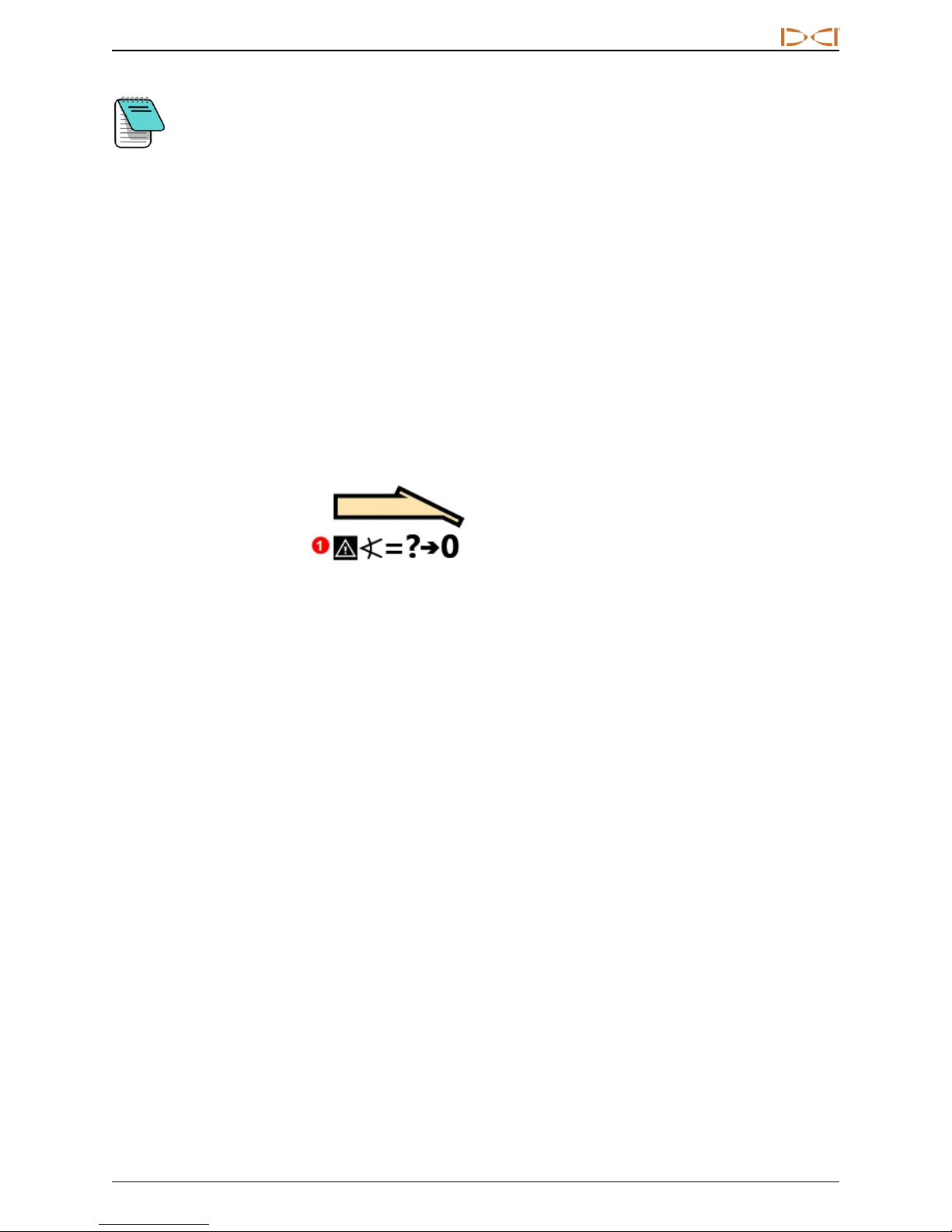
When transmitter pitch is unavailable at the receiver due to range restrictions or interference, Aurora will
assume the transmitter has a pitch of zero for depth and predicted depth readings. In this case, it will display
Pitch Assumed Zero beneath the transmitter icon.
1. Pitch assumed zero
Transmitter Pitch Unavailable
If the drilling angle prior to loss of pitch was at or near zero, a predicted depth reading can still be fairly
accurate. If the last known pitch was not near zero, the predicted depth calculation will not be accurate. In
either case, the predicted depth calculation will become increasingly inaccurate with each rod drilled with no
pitch data.
The safest course of action is to stop drilling until pitch data is restored. Options available to the receiver
operator to increase signal reception between the transmitter and receiver include changing the transmitter
frequency (if compatible), off-track locating, and target steering.
DigiTrak®Aurora®DisplayOperator's Manual 23
Page 30
DIGITALCONTRO LINCORP ORATED
Target Steering
Instructions for setting up the receiver for Target Steering®can be found in the operator's manual for your
system. Most of the setup for Target Steering is done by the receiver operator. This section discusses how
to use Target Steering data on the Aurora display.
DigiTrak SE guidance systems use a simpler form of steering called Remote Steering that provides only left
and right steering information. Refer to the SE operator's manual for instructions on Remote Steering.
In general, Target Steering should be used to maintain a bore path, not to bring a significantly off-course bore
back on track. If the drill head is already significantly off course, use front and rear locate methods as
described in your DigiTrak system operator’s manual to get back on course.
After learning the concepts of Target Steering, practice its use before using on a jobsite where
time and money are at a premium. A Look-Ahead Locating animation is also available on our
YouTube channel at www.YouTube.com/DCIKent. If you need further assistance, please
contact DCI Customer Service.
Target Steering requires a stable signal from both the transmitter and receiver.
Steering to the Target
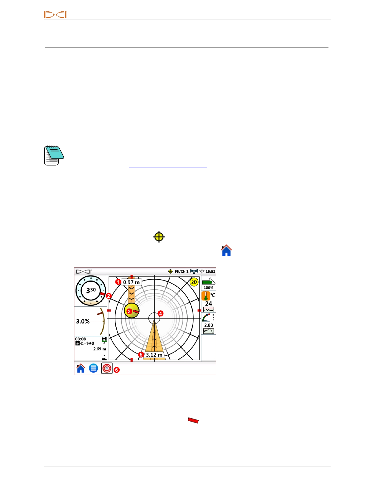
Once the target depth has been entered on the receiver, Aurora automatically displays the Target Steering
screen. The flashing Target Steering icon displays in the Status bar as long as Aurora is receiving target
steering information. To hide the Target Steering screen, tap Home .
1. Current depth below receiver
2. Current roll
3. Projected destin atio n on
current head ing
4. Target
5. Horizontal distance to target
6. Target steering icon
Target Steering Screen, Steering Toward Target
The target in the center of the previous image represents the target depth entered in the receiver for a point
directly below it. The yellow steering indicator ball represents the projected destination or current “aim point”
of the drill head in relation to the target. The red marker inside the steering indicator indicates the current
roll position of the drill head. This screen shows that the drill head is currently estimated at 1.0 m below the
horizontal plane of the receiver and the target is 3.1 m ahead.
24 DigiTrak®Aurora®DisplayOperator's Manual
Page 31
DIGITALCONTRO LINCORP ORATED
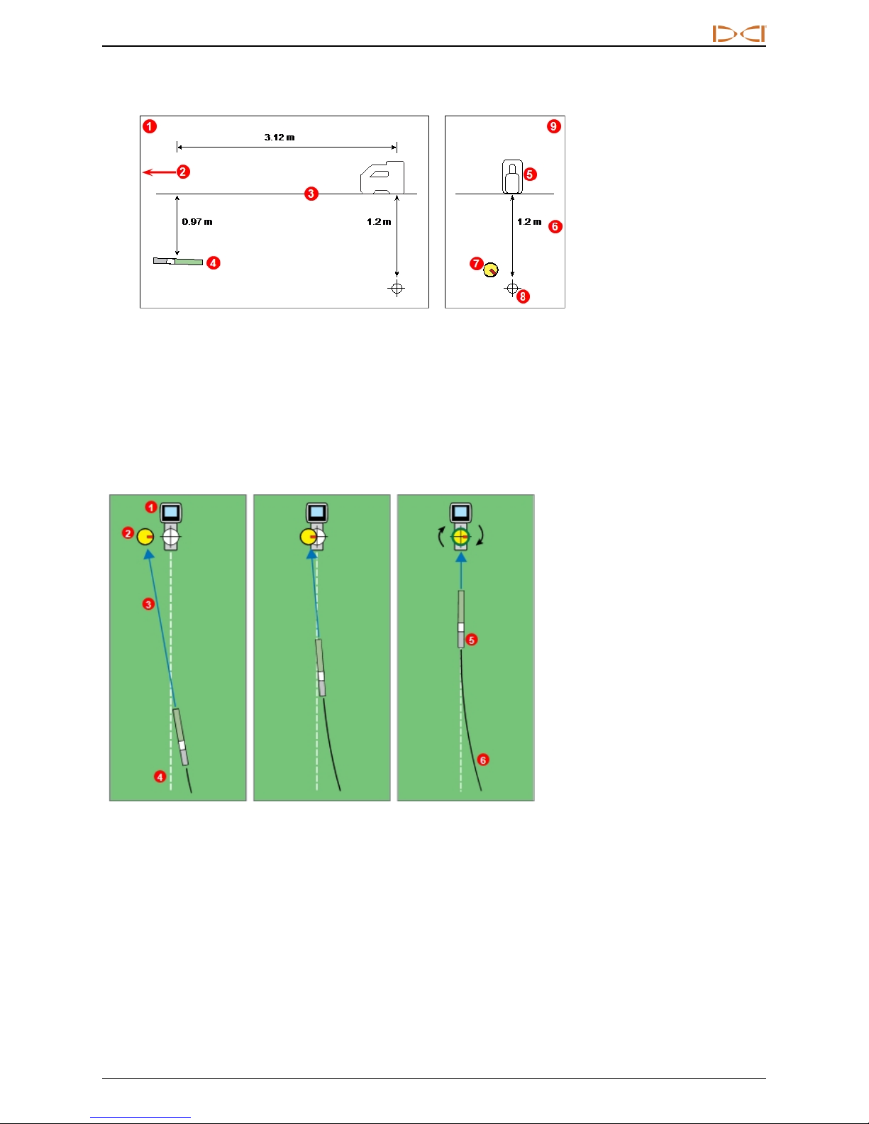
This Target Steering screen shows the following scenario:
1. Side view
2. Toward drill rig
3. Ground
4. Transmitter
5. Receiver
6. Target dept h
7. Projected destin atio n
8. Target
9. Rear view
Transmitter, Target, and Receiver
The steering indicator shows that the drill head is heading above and to the left of the target. To bring the ball
back on target, rotate the drill head so the red marker in the ball points toward the target. The drill head is then
steering correctly to reach the intended bore path (see following figure) to reach the target.
As shown in the example below, the steering indicator will help you line up the drill head with the receiver
before it reaches the target.
Turning the drill head
to center the yellow
steering indicator ball
Redu cing the turn as th e
steering indicator
approaches th e t arget
Target Steering and the Steering Indicator, Overhead View
The left panel of the target steering scenario above suggests that on the current heading, with no further
steering corrections, the drill head will arrive to the left of the target below the receiver (depth is not reflected
on this 2-dimensional drawing). However, as the drill head moves in relation to the target (center panel), the
steering indicator will also move. The right panel shows the transmitter (drill head) having reached the
intended bore path and drilling directly toward the target.
DigiTrak®Aurora®DisplayOperator's Manual 25
1. Receiver
2. Steering indicator
3. Projected destin atio n
4. Intended bore path
5. Transmitter
6. Actual bore path
Drilling (rotatin g) directly
toward the target
Page 32
DIGITALCONTRO LINCORP ORATED
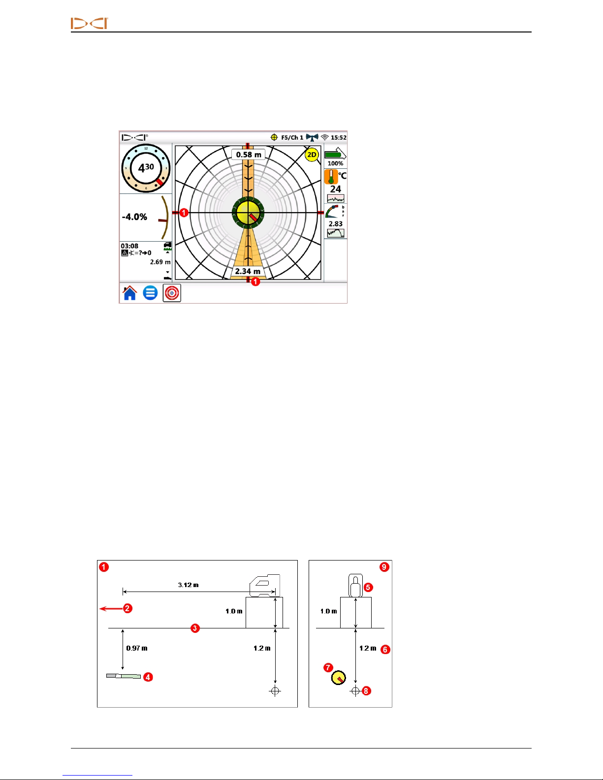
While drilling, monitor the yellow steering indicator ball closely, make small steering adjustments, and watch
and wait for the results. The closer the drill head is to the receiver, the more sensitive the steering indicator
becomes. As it approaches the target, reduce the amount of the turn. When the indicator is centered on the
target and surrounded by a green ring, the drill head is correctly positioned on the intended bore path to drill
toward the target.
1. Alignment marks
Target Steering Screen, Drill Head Aligned On
Intended Bore Path
This screen shows the drill head correctly aligned to reach the target at 2.3 m ahead, and the drill head is
currently 0.6 m below the horizontal plane of the receiver. At this point, the closer the pitch is to zero, the less
the indicator will tend to move above or below the target. The red alignment marks help show when the drill
head is aligned with the target.
The yellow steering indicator ball can only show steering corrections within the limits of the target steering
screen. Once the ball nears the edge, or has "pegged", drilling farther off course will not be reflected on the
remote display. Make the necessary steering corrections and when the ball begins moving closer to the
target, be prepared to reduce the amount of the turn.
Target Steering in Interference Areas
In areas of passive and/or active interference, it may help to elevate the receiver above the ground. In the
example below, the receiver is placed 1 m above the ground. To compensate, the target depth value must
include the elevated height; 1 m plus 1.1 m equals 2.1 m.
Transmitter, Target, and Raised Receiver
26 DigiTrak®Aurora®DisplayOperator's Manual
1. Side view
2. Toward drill rig
3. Ground
4. Transmitter
5. Receiver
6. Target dept h
7. Projected destin atio n
8. Target
9. Rear view
Page 33
DIGITALCONTRO LINCORP ORATED
Understanding the Steering Indicator Ball
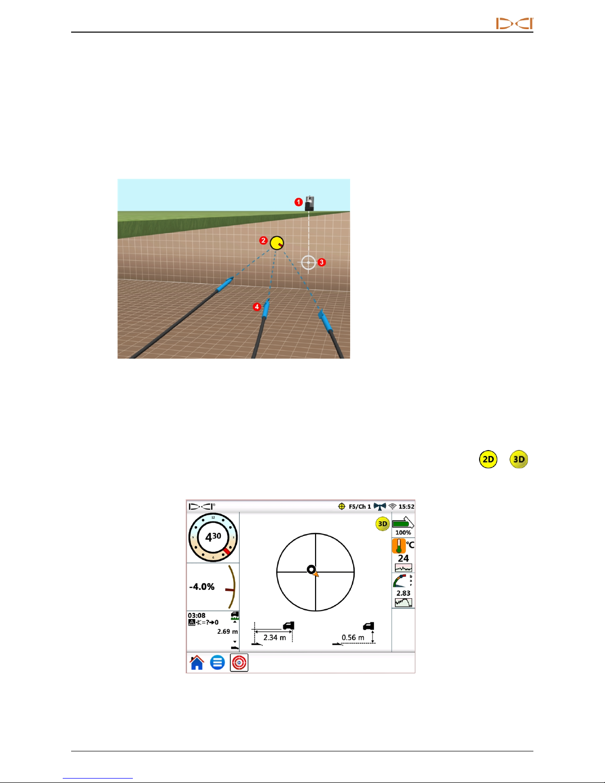
As shown previously, the yellow steering indicator ball (projected destination) being to the left of the target
does not necessarily mean the drill head is also currently to the left of the target. While each example below
requires a different amount and duration of steering correction, all need to move the same direction: right and
down.
It is important to take into consideration the steering over the last few rods before making additional
adjustments; you may already be drilling in the direction Target Steering is instructing.
1. Receiver
2. Projected destin atio n
3. Target
4. Drill head with transmitter
Sample Target Steering Drill Head Locations
Classic View
In addition to the three-dimensional target steering screen, Aurora can also display the classic two-
dimensional Target Steering view from previous versions of DigiTrak remote displays. Tap either or
at the upper right of the screen to switch to 2D or 3D views at any time.
Target Steering, Classic Two-Dimensional View
DigiTrak®Aurora®DisplayOperator's Manual 27
Page 34

DIGITALCONTRO LINCORP ORATED
Turning Target Steering Off
The flashing Target Steering icon in the Status bar indicates when Target Steering data is being
received, even if you are on a different screen. If you are viewing the Target Steering screen when Aurora
stops receiving Target Steering information from the receiver, the display will stop showing data.
Until Aurora is powered off, the Target Steering function remains loaded so if Target Steering data resumes,
Aurora can continue processing it without interrupting your current task.
28 DigiTrak®Aurora®DisplayOperator's Manual
Page 35
DIGITALCONTRO LINCORP ORATED
Working with TensiTrak
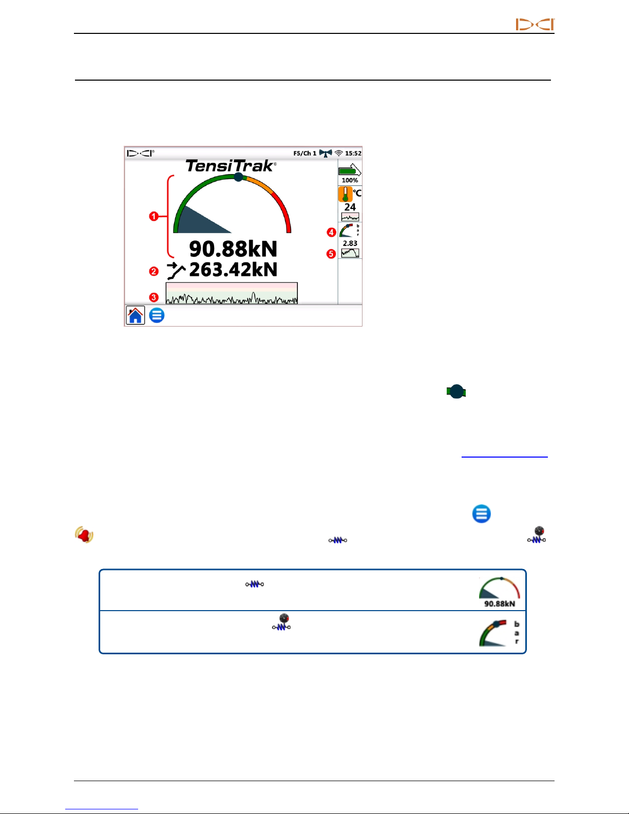
When Aurora detects tension data provided by a TensiTrak®pullback and pressure monitoring system, it
automatically displays the TensiTrak tension gauge.
1. Current pullback tension
2. Maximum pullback tension
3. Tension history
4. Fluid pressure
5. Fluid pressure hist ory
TensiTrak Gauge
A TensiTrak system provides both product pullback tension and annular fluid pressure. The maximum
recorded tension (in this case, 263.42 kN) also displays on the gauge as a blue circle .
The tension history graph displays about 30 minutes of historical data; new data plots on the right, pushing
older data to the left.
For details on working with TensiTrak, please refer to the operator's manual, available at www.DigiTrak.com.
Setting Warning Levels
To set TensiTrak tension or fluid pressure warning and critical levels, go to the Main Menu , tap Alarms
, then select either the TensiTrak Pullback Tension or TensiTrak Pullback Fluid Pressure
tab.
Menu shortcut
Menu shortcut
For tension alarms, tap and hold the pullback tension
gauge.
For fluid pressure alarms, tap and hold the fluid pressure
gauge.
DigiTrak®Aurora®DisplayOperator's Manual 29
Page 36
DIGITALCONTRO LINCORP ORATED
Working with the MFCB
For instructions on making the power and data connections between the Multi-Function Cable Box (MFCB)
and Aurora, please read the MFCB Operator's Manual, available at www.DigiTrak.com.
Enabling the MFCB
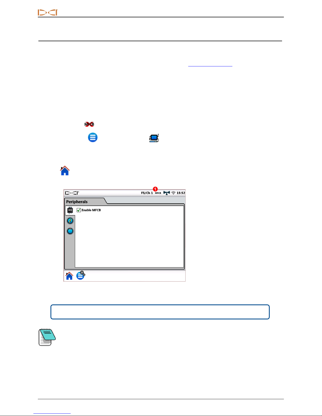
Until you have made the proper power and data connections between the MFCB and Aurora, the check box
to Enable MFCB on the MFCB tab of the Peripherals screen (shown below) will be grayed out as
unavailable.
Once the MFCB is properly connected to Aurora, an MFCB icon displays in the Status bar. If the MFCB
appears as disabled , enable it as follows:
1.
Tap Main Menu , then tap Peripherals .
2. Tap the MFCB tab (shown below).
3. Tap the check box to Enable MFCB. This selection will remain in effect even after a power cycle.
4.
Tap to return to the Home screen.
Enabling MFCB on the Peripherals Screen
Menu shortcut Tap and hold MFCB in the Status bar.
1. MFCB is con nected
To use a standard battery-powered transmitter while the MFCB is connected, simply clear the
Enable MFCB check box. Aurora will now receive drilling data from the receiver.
30 DigiTrak®Aurora®DisplayOperator's Manual
Page 37
DIGITALCONTRO LINCORP ORATED
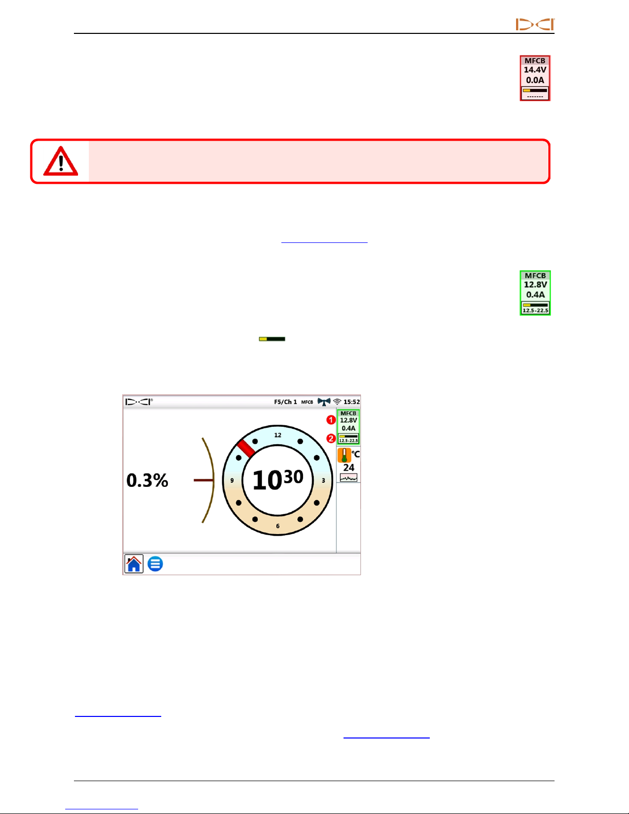
Before making any changes to the wire in the drill pipe, ensure the voltage/amp icon is red—
indicating the MFCB is off—to avoid electric shock. If it is green, tap to turn it off.
After the MFCB is correctly connected and enabled, Aurora replaces the transmitter battery icon at
the top right of the screen with a display of the voltage and amps at both the MFCB and transmitter.
This new portion of the screen functions as an on/off button for using the MFCB. Upon first use after
Aurora is turned on, this MFCB button will be bordered and shaded in red, indicating the MFCB is not
yet sending power to the transmitter.
Using a Cable Transmitter
Connect and enable the MFCB as described in Enabling the MFCB on page 30.
Applying Power to the Transmitter
To send power to the transmitter, tap the red button; it turns green to indicate the transmitter is now
powered, and current voltage and amperage information displays along with other transmitter data
such as roll and pitch.
In this example for a cable transmitter, the MFCB is supplying 12.8 VDC and 0.4 A of power to the
transmitter. The voltage at the transmitter is in the range of 12.5–22.5 VDC.
Other information displayed on the Home screen is the same as when using a standard battery-powered
transmitter.
1. Volts and amps at MFCB
2. Voltage range at transmitter
Home Screen with MFCB Power Readings
Monitor the voltage at the transmitter closely, since the length of cable or quality of connections may cause
the voltage to drop below the level necessary for the cable transmitter to function.
Using a Steering Tool Transmitter (SST)
For instructions on using the Steering Tool transmitter, please read the SST®operator’s manual, available at
www.DigiTrak.com.
Connect and, if necessary, enable the MFCB as described in Enabling the MFCB on page 30.
DigiTrak®Aurora®DisplayOperator's Manual 31
Page 38
DIGITALCONTRO LINCORP ORATED
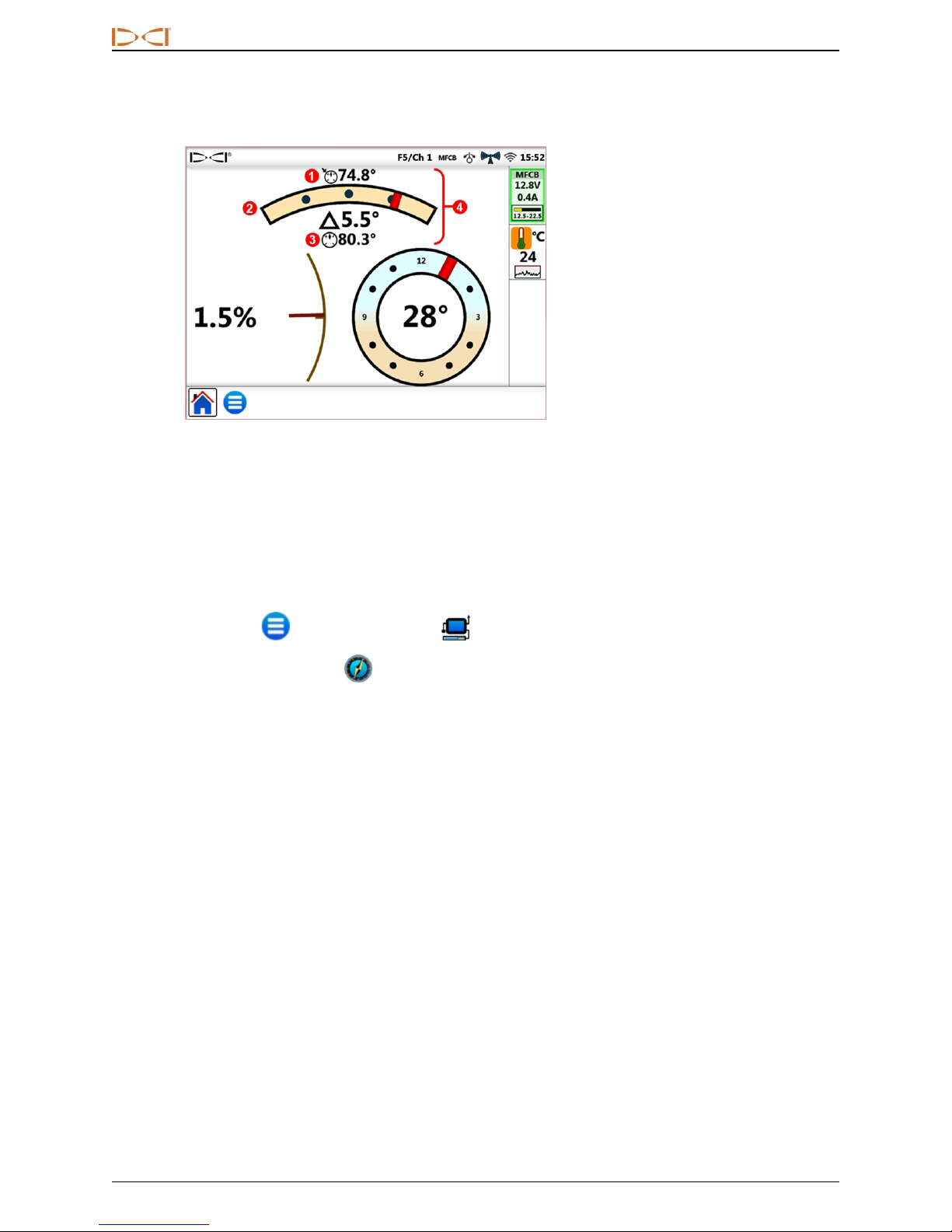
When Aurora detects that a steering tool is connected to the MFCB, it adds a heading indicator to the
display.
1. Heading reference (tap and
hold to set)
2. Deviation f rom heading
reference
3. Current heading
4. Heading in dicat or
Home Screen with SST Heading Indicator and
MFCB Power Readings
As shown in the above image, roll accuracy for SST changes from a 24-position to a much more accurate
360° indicator.
Setting a Heading Reference
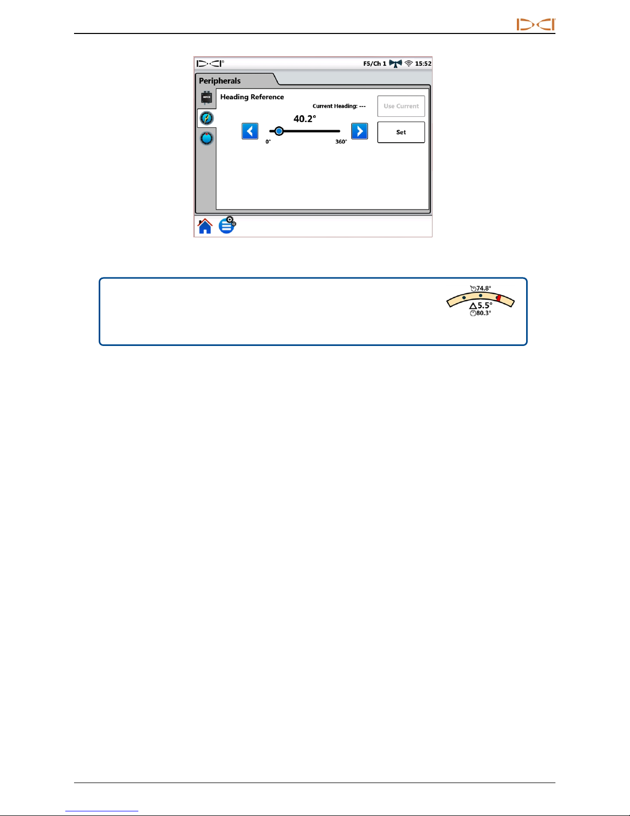
To set the desired heading reference:
1.
Tap Main Menu , then tap Peripherals .
2.
Tap the Heading Reference tab (shown below).
3. Tap the blue arrow buttons or drag the slider control to select the desired heading reference.
4. Tap Set to set the heading reference and return to the Home screen.
The Set button is unavailable until the heading reference changes.
If Aurora is detecting a valid heading from the SST, this value will display beside Current Heading: and the
Use Current button will be available. In this case, you can tap Use Current to set this value as the heading
reference.
32 DigiTrak®Aurora®DisplayOperator's Manual
Page 39
DIGITALCONTRO LINCORP ORATED
SST Heading Reference Screen
Menu shortcut
Tap and hold the heading indicator on the Home
screen.
Heading Indicator
DigiTrak®Aurora®DisplayOperator's Manual 33
Page 40
DIGITALCONTRO LINCORP ORATED
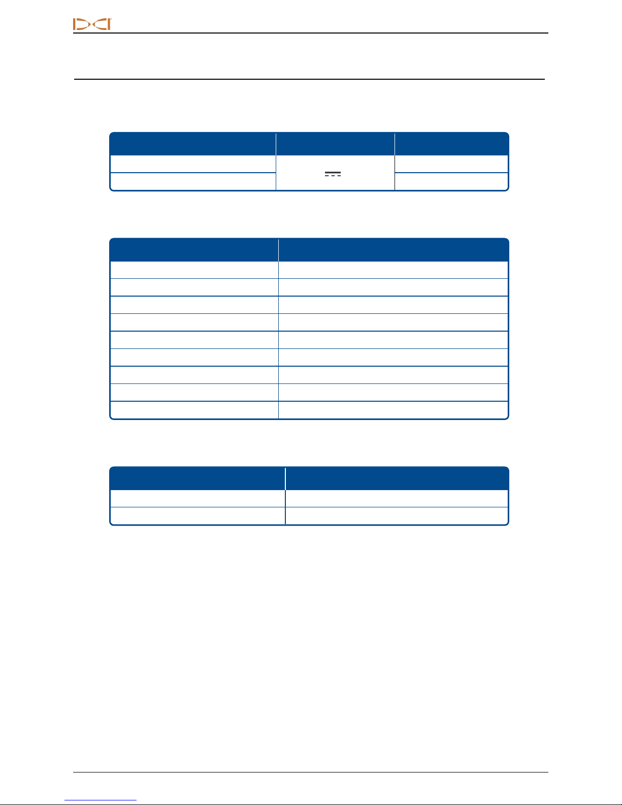
Appendix A: System Specifications
Power Requirements
Device Operational Voltage Operational Current
DigiTrak Aurora AF10 Display
10–28 V (nominal)
DigiTrak Aurora AP8/AF8 Display 1.75 A max
Environmental Requirements
Category Value
Relative humidity <90%
Operating temperature -20 to 60° C
Dust and water ingress IP66
Handling drop (1 meter) IEC 61010-1
Vibration SAE J1455
Electromagnetic interference EN 55024/CISPR24, IEC 61000-4-3,4,6,8
Electromagnetic compatibility EN 55022/CISPR22 (Class B)
Electrostatic discharge IEC 61000-4-2
Operating altitude, maximum 2000 m
Networking Requirements
2.10 A max
Connection Type Requirement
Wi-Fi IEEE 802.11 b/g/n
Bluetooth 2.1+EDR, Power Class 1.5
Storage and Shipping Requirements
Temperature
Storage and transportation temperature must remain within -40 to 65° C.
Packaging
Ship in original carrying case or packaging of sufficient durability to prevent mechanical shock to equipment
during transportation.
34 DigiTrak®Aurora®DisplayOperator's Manual
Page 41
19625 62nd Ave S, Suite B103
Kent Washington 98032, USA
425.251.0559, 800.288.3610
[email protected], www.DigiTrak.com
DCIStandard Warranty
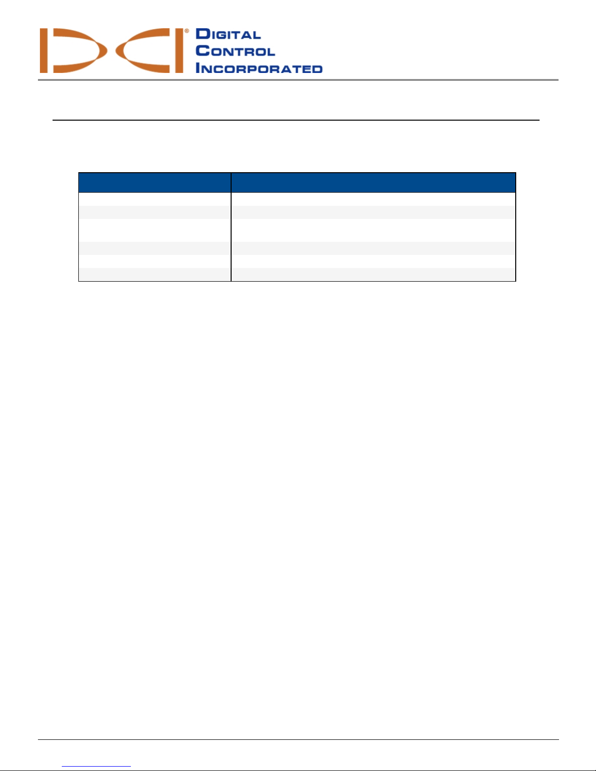
DCI warrants that it willeither repair or replaceany product that fails to operate in conformity to DCI’spublished specifications at the time of
shipment due to a defect in materials or workmanship during the warranty per iod for that product, subject to the terms set forth below.
Category Warranty Period
Falcon Transmitters (19 ” and 15 ”) Three years from da te of purchase or first 50 0 hours o f use, whichever occurs first.
All Other Transmitters Ninety days from date of p urchase
Receivers, Remote Displays, Battery
Charge rs and Rechargea ble Batteries
Software* One year from date of p urchase
Other Accessories Ninety days from date of p urchase
Service/Repair Ninety days from date of repair
* For s oftware products, in lieu of the warranty set forth above, DCI warrants that it will either update any defective software to bring it into material
compliance with DCI’s specifications for s uch s oftware, or refund the purchase price paid for t he software.
One year from date of p urchase
Terms
l The 3-yr/500-hr war ranty period for a Falcon transmitter is conditioned on registration of the purchase with DCI within 90 days of the date of
purchase. If the customer failsto register the pur chase during this time frame, the war ranty period for the transmitter willinstead be ninety
days from date of purchase.
l Warranty coverage for a warranty replacement transmitter shall tie back to the original transmitter(s) submitted for warranty coverage. For
example, if a Falcon transmitter is owned for one year and used for 250 hours, the warranty coverage for the replacement will be an
additional two years or an additional 250 hours of use, whichever comes first.
l “Hour s of use” for purposes of the F alcon transmitter warranty means activerun-time hour s, as measured internally by F alcon transmitters.
l In the event of a valid warranty submission, the choice of remedy (for example, to repair or replace a defectiveproduct or, in the case of
defective software, to update or refund), shallbe at DCI’ssole discretion. DCI reserves the right to use remanufactured replacement parts
for repairs.
l The above warranties only apply to new products purchased directly from DCI or fr om a DCI-authorized dealer.
l The ultimate determination of whether a product qualifies for warranty replacement shallbe at DCI’s sole discretion.
Exclusions
l Transmitters that have exceeded the maximum temperature, as indicated by the system.
l Defect or damage caused by misuse, abuse, improper installation, improper storage or transport, neglect, accident, fire, flood, use of
incorrect fuses,contact with high voltages or injurioussubstances, use of system components not manufactured or supplied by DCI, failure
to follow the operator’smanual, use other than that for which the product was intended or other events beyond the control of DCI.
l Any transmitter used with an improper housing, or damage causedto a transmitter from improper installation into or retrieval from a
housing.
l Damage during shipment to DCI.
Any modification, opening up, repair or attempted repair of a product, or any tampering or removal of any serial number, label or other
identification of the product, will void the warranty.
DCI does not warrant or guarantee the accuracyor completeness of data generated by HDD guidance/locating systems. The accuracyor
completenessof suchdata may be impacted by a variety of factors, including (without limitation) active or passive interfer ence and other
environmental conditions, failure to calibrate or use the device pr operly and other factors. DCI alsodoes not war rant or guarantee, and disclaims
liabilityfor, the accuracyand completenessof any data generated by any external source that may be displayed on a DCI device, including
(without limitation) data received from a drillr ig.
DCIStandard Warranty 1
Page 42

DIGITALCONTRO LINCORP ORATED
DCI may make changes in design and improvements to products from time to time. DCI shallhave no obligation to upgrade any previously
manufactured DCI product to include any such changes.
THE FOREGOING IS THE SOLE WARRANTY FOR DCI PRODUCTS (OTHER THAN THE 5-YR/750-HR EXTENDED WARRANTY F OR
FAL CON 15/19” TRANSMITTERS). DCI DISCLAIMS ALL OTHER WARRANT IES, EXPRESS OR IMPLIED, INCLUDING BUT NOT
LIMITED T O IMPLIED WARRANTIES OF MERCHANTABILITY AND FITNESS FOR A PARTICULAR PURPOSE, IMPLIED
WARRANTY OF NON-INFRINGEMENT, AND ANY IMPLIED WARRANTY ARISING FROM COURSE OF PERFORMANCE, COURSE
OF DEALING, OR USAGE OF TRADE, ALL OF WHICH ARE HEREBY DISCLAIMED.
In no event shallDCI or anyone else involved in the creation, production, sale or delivery of the DCI pr oduct (“partners”) be liable for any damages
arising out of the use or inability to use the DCI product, including but not limited to indirect, special, incidental, or consequentialdamages, or for
any cover, lossof information, profit, revenue or use, based upon any claim for breach of warranty, breach of contract, negligence, strictliability,or
any other legaltheory, even if DCI has been advised of the possibilityof such damages. In no event shallDCI or its partners’ liability exceed the
purchase price for the product.
This warranty is not assignableor transferable. This warranty isthe entire agreement between DCI and pur chaser, and may not be expanded or
amended in any way other than in writing by DCI.
Product demonstrations
DCI personnel may be present at a job site to demonstrate basic usage, features, and benefits of DCI pr oducts. DCI personnel are present onlyto
demonstrate a DCI product. DCI does NOT provide locating services or other consulting or contracting services.DCI does not assume any duty to
train the user or any other person, and does not assume responsibility or liability for the locating or other work performed at a job site at which DCI
personnel or equipment are or have been present.
Translations
This document may be a translation of the originalEnglish language version. T he purpose of thistranslation is to assist the pr oduct user.
However, in the event of any discrepancy in meaning or interpretation between the translation and the originalEnglish language version, the
original English language version shall control. A copy of the originalEnglish language version of this document may be found at
www.DigiTrak.com.
2 DCIStandard Warranty
Page 43
19625 62nd Ave S, Suite B103
Kent Washington 98032, USA
425.251.0559, 800.288.3610
[email protected], www.DigiTrak.com
END-USER PRODUCT LICENSE AGREEMENT: AURORA
IMPORTANT: PLEASEREAD THE TERMS AND CONDITIONS OF THIS LICENSE AGREEMENT CAREFULLY BEFORE USING THE
AURORA PRODUCT .
This End-User License Agreement ("license") is an agreement between DIGITAL CONTROL INCORPORATED (“DCI”) and the entity or
individual (“ you”) that purchases the AURORA®product from an authorized distributor of DCI products. By using the AURORA product, you
agree to be bound by the terms of thislicense.
1. Definit ions
a. “AURORA” means color touchscreen displayand intelligent platform for use with horizontal directional dr illrigs that is manufactured by
DCI.
b. “DCI GUIDANCE SYSTEM” means any horizontal directional drilling guidance system manufactured by DCI that is, at any given time,
designated by DCI as being interoper able with AURORA (as indicated in the associated product documentation for AURORA).
c. “SOFTWARE” means the software and firmware embedded into AURORA upon purchase of the AURORA unit and related
documentation, including any bug fixes, modifications and updates to such software provided by DCI to you under this license.
SOFTWARE shallalso include any software application for AURORA, whether installed upon initial purchase or purchased or validly
obtained by you in the future, that is expresslyauthorized by DCI for use with AURORA.
d. “TERRITORY” means the United States, Canada, each member state of the European Union, Australia, New Zealand, China, India
and Russia.
2. Grant of Non-Exclusive License. DCI grants you a nonexclusive, royalty-free (other than royaltiesor fees specificallyidentified with
respect to applications purchased separately in the future), non- transferable and non-sublicensablelicense to use the SOFTWARE in object
code for m, solely for your use with the AURORA unit on which the SOFTWARE came originally installed (as a single integrated product), for
ordinary course horizontal directional drilling purposes, together with any applicable DCI GUIDANCE SYSTEM in the TERRITORY.
3. License Restrictions. Thislicense is subject to the following restrictions:
l the SOFTWARE may not be used with any device other than the particular AURORA unit on which the SOFTWARE came originally
installed;
l you agree not to make any copies of the SOFTWARE;
l neither the SOFTWARE nor the associated AURORA unit may be used in any geographicterritory other than the TERRITORY; and
l neither the SOFTWARE, the associated AURORA unit nor any associated DCI GUIDANCE SYSTEM may be repaired by, or
submitted for repair to, any person or entity other than a person or entity expressly authorized by DCI to perform such r epairs (as of the
date of thislicense, DCI isthe onlyperson or entity authorized to perform such repairs).
4. Ownership. The SOFTWARE is licensed, not sold, and nothing in this licenseshallbe construed to convey any titleor ownership rights. You
expresslyacknowledge that, as between you and DCI, DCI owns all worldwide right, title and interest in and to the SOFTWARE, including all
copyrights and other intellectual pr operty rights therein. Allr ights not expresslygranted by thislicense are hereby reserved by DCI and its
licensors.
5. Intellectual Property. You acknowledge that the SOFTWARE constitutesand containstrade secrets of DCI, and in order to protect such
trade secrets and other interests that DCI may have in the SOFT WARE, you agree not to disassemble, decompile,reverse engineer or
otherwiseattempt to derive source code fr om the SOFTWARE or the associated AURORA unit, nor to permit any other person or entity to
do so, except to the extent suchrestrictions are prohibited by law. Except as expresslyprovided in this license, thislicense does not grant you
any rights to patents, copyrights, trade secrets, trademarks or any other rights with respect to the SOFTWARE.
6. Data Rights. F uture upgrades to the SOFTWARE, or future software applications for AURORA, may enable you to store HDD locate data
generated by a DCI GUIDANCE SYSTEM locally on the AURORA unit and/or in remote data storage. DCI may seek to collect this HDD
locate data solelyto pr ovide aggregate industry data summaries or reports, to provide customer service to you, or for use with AURORA
software applicationsor other DCI products or services,subjectin each case to the following limitations. You may “opt out” of any such data
collection by DCI by indicating this decision on DCI’s pr oduct registration website at access.DigiTrak.com. You hereby grant DCI a perpetual,
irrevocable, worldwide, royalty-free, assignable, sublicensable, non-exclusive license to use, reproduce, display, modifyand distribute any
data generated by the SOFT WARE, the associated AURORA unit and each DCI GUIDANCE SYSTEM used in conjunction ther ewith;
provided that DCI willnot discloseyour project-specific data to any third party (excluding any service provider of DCI subject to similar
confidentiality obligations) without your consent ( for purposesof clarity, the for egoing shall not restrictDCI from disclosing aggregate data
incorporating your data) other than as required by law; provided further, that such license shall terminate if and immediately upon your
electionto “opt out” of such data collection as specified above. You agree not to sell, lease or otherwise provide such data to any third party
nor to authorize any third party to use, reproduce, display, modify or distribute any suchdata without DCI’s consent.
®
DCIEnd-User License Agreement ( EULA) 1
Page 44

DIGITALCONTRO LINCORP ORATED
7. Suppo rt Services. Thislicense does not obligate DCI to provide you with any support services related to the SOFTWARE. However,
registering your AURORA with DCI through access.DigiTrak.com willentitle you to one year of free upgrades for the SOFTWARE.
8. Limited Warranty. DCI provides a limited warranty for the SOFTWARE. Please refer to the section of your AURORA manual titled “Limited
Warranty”, or to www.DigiTrak.com, for the terms and limitations of this warranty.
AURORA ACCEPTS DATA FROM MULTIPLE SOURCES. DCI DOES NOT WARRANT OR GUARANTEE, AND DISCLAIMS LIABILITY
FOR, THE ACCURACY AND COMPLETENESS OF ANY DATA GENERATED BY ANY EXTERNAL SOURCE OR DERIVED FROM
DATA GENERATED BY ANY EXTERNAL SOURCE, INCLUDING ( WITHOUT LIMITATION) FROM ANY HDD DRILL RIG. DCI DOES
NOT WARRANT OR GUARANTEE THE ACCURACY OR COMPLETENESS OF DATA GENERATED BY HDD GUIDANCE SYSTEMS.
THE ACCURACY OR COMPLETENESS OF SUCH DATA MAY BE IMPACTED BY A VARIETY OF FACTORS, INCLUDING (WITHOUT
LIMITATION) ACTIVE OR PASSIVEINTERFERENCE (INCLUDING FROM SALT WATER) AND OTHER ENVIRONMENTAL
CONDITIONS, F AILURE TO CALIBRATE OR USE T HE DEVICE PROPERLY AND OTHER FACTORS.
9. LIMITATION OF LIABILITY. DCI’S TOTAL CUMULATIVE LIABILITY T O YOU FROM ALL CAUSES OF ACTION AND UNDER ALL
THEORIES OF LIABILITY WILL BE LIMITED T O THE VALUE OF THE SOFTWARE. IN NO EVENT WILL DCI BE LIABLE F OR ANY
DIRECT , INDIRECT OR CONSEQUENTIAL DAMAGES (INCLUDING, WIT HOUT LIMIT ATION, LOST PROFITS, BUSINESS
INTERRUPTION, OR LOST INFORMATION) ARISING OUT OF OR RELATED TO YOUR USE OF OR INABILITY TO USE T HE
SOFTWARE, WHETHER SUCH LIABILITY ARISES FROM ANY CLAIM BASED UPON CONTRACT, WARRANTY, TORT (INCLUDING
NEGLIGENCE), STRICT LIABILITY OR OTHERWISE, AND WHETHER OR NOT DCI HAS BEEN ADVISED OF THE POSSIBILITY OF
SUCH DAMAGES. DCI SHALL HAVE NO LIABILITY WITH RESPECT TO THE CONTENT OF THE SOFTWARE OR ANY PART
THEREOF, INCLUDING BUT NOT LIMIT ED TO ERRORS OR OMISSIONS CONTAINED THEREIN, LIBEL, INFRINGEMENTS OF
RIGHTS OF PUBLICITY, PRIVACY, TRADEMARK RIGHTS, BUSINESS INT ERRUPTION, PERSONAL INJURY, LOSS OF PRIVACY,
MORAL RIGHTS OR T HE DISCLOSURE OF CONFIDENTIAL INFORMATION.
ONE OR MORE REPRESENTATIVES OF DCI OR OF A RESELLER OF DCI MAY ARRIVE AT YOUR JOB SITE FOR PURPOSES OF
DEMONSTRATING THE FEATURES AND BENEFITS OF THE AURORA PRODUCT WITH A DCI GUIDANCE SYSTEM. YOU HEREBY
EXPRESSLY ACKNOWLEDGE AND AGREE THAT, AS A RESULT OF THE PRESENCE OF SUCH DCI REPRESENTATIVE AT A JOB
SITE AND DEMONSTRATION OF SUCH DCI PRODUCTS (AND ASSOCIATED ADVICE REGARDING THE USE OF SUCH DCI
PRODUCT S), DCI DOES NOT ASSUME ANY DUT Y TO TRAIN YOU OR ANY OTHER PERSON AT A JOB SITE AND DCI SHALL HAVE
NO LEGAL RESPONSIBILITY OR LIABILITY FOR DRILLING, INSTALLATION, HDD GUIDANCE OR OTHER WORK PERFORMED AT
ANY SUCH JOB SITE.
10. Infring ement. DCI willdefend or settle, at itsoption and expense, any suit against you alleging that the SOFTWARE and/or the associated
AURORA unit infringes any United States patent(s), trademarks or copyrights or misappropriates any trade secrets, when used for its
normal purpose. As a condition to such obligation, you agree to (a) notify DCI promptly in writing of such suitor infringement, (b) provide DCI
all information and assistance reasonably necessary to settle or defend the suit, and ( c) grant DCI sole authority and control of the defense
or settlement of the suit. DCI’s obligationsunder this section will not apply, however, to any claim based on (i) any modification to the
SOFTWARE or AURORA by anyone other than DCI, (ii) any use of the SOFTWARE or AURORA that is outside the ordinary course
intended use of the product, (iii) any use of the SOFTWARE or AURORA as par t of an infringing process, and (iv) any combination of the
SOFTWARE or AURORA with any product or technology not supplied by DCI (or methods combining use of the SOFTWARE or AURORA
with any product or technology not supplied by DCI), except for combinationswhere you establish by clear and convincing evidence that the
SOFTWARE or AURORA is the primary cause of the infringement. In addition, DCI’s obligations under thissection will not apply to
consequentialor other damages excluded under Section 9 above. To settle or resolve any such claim, DCI may, at its sole option and
expense, either replace or modify the SOFTWARE or AURORA so that it becomes non-infringing or procure a license for you to continue
using the SOFTWARE and AURORA; if DCI determines that neither of such alternativesisfinanciallyor otherwise practical, DCI may
repurchase the AURORA unit at its depreciated value based on a 5-year linear depreciation schedule.
11. Export and Compliance with Law. You agree not to export or r e-export the SOFTWARE, the associated AURORA unit, or
accompanying documentation, in violation of any applicable laws or regulations, including without limitationthe U.S. Export Administration
Regulations, as well as end-user, end-use and destination restrictions issued by the U.S. and other governments. You further agree to
complywith allother laws and regulationsapplicable to the SOFTWARE and the associated AURORA unit. Without limiting the foregoing,
you agree to review local laws and regulations governing the use of GPS before using any AURORA applicationsthat employ GPS
technology.
12. Termination. In the event that you breach any provision of Section 3 or Section 13(a) , thislicense shall immediately terminate and become
null and void. DCI may terminate this license if you fail to complywith any other terms and conditions of this license by sending written notice
of such termination to you. The exercise by DCI of any remedy under this license will be without prejudice to its other remedies under this
license or otherwise.
13. General
a. You may not assign, sublicense or otherwise transfer thislicense, in whole or in part, by operation of law or otherwise, without DCI’s
express prior written consent. Any attempt to assign this license without such consent willbe void. In the event you wish to resell, lease
or otherwise transfer the AURORA unit on whichthe SOFTWARE is installed, such transfer will render thislicense nulland void, and
such purchasing person or entity will be required to obtain a separate license from DCI.
b. This license r epresents the entire agreement concerning the pr ogram between you and DCI, and it supersedes any prior proposal,
representation, or understanding between the parties. If any provision of this license is held by a court of competent jurisdiction to be
void, invalid, unenforceable or illegal, then such provision will be construed, limited or, if necessary, severed to the extent necessary to
2 DCIEnd-User License Agreement (EULA)
Page 45

DIGITALCONTRO LINCORP ORATED
eliminate such invalidity and unenforceability. The other provisions of this license willremain in full force and effect. This license may only
be modified in writing, signed by an authorized representative of you and DCI (which willrequire a new registration on
access.DigiTrak.com by such purchasing person or entity).
c. This license shallbe governed by and construed in accordance with the laws of the State of Washington (without regard to its or any
other jurisdiction’schoiceof law principles). All disputes arising out of or in relation to this license shall be submitted to the exclusive
jurisdiction of the state and federal courts of Washington, USA. Nothing in this license shall restrict DCI’s right to bring an action against
you in the jurisdiction where your place of business is located. The United Nations Convention on Contracts for the International Sale of
Goods does not applyto thislicense.
DCIEnd-User License Agreement ( EULA) 3
 Loading...