

Page 1
1
Version 1-09
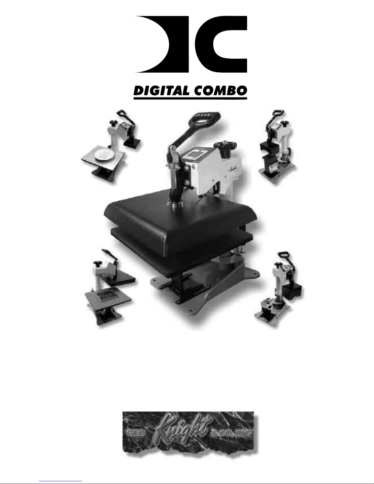
Digital Combo
Multi-Purpose Press
Page 2

2
Contents
Introduction ............................................................................................................ 3
Setup & Suggestions ......................................................................................... 4
Normal Operation .................................................................................................. 5
Normal Operating Mode ................................................................................... 5
Setting Temperature .......................................................................................... 5
Setting Time ...................................................................................................... 6
Pre-Press Timer ................................................................................................. 6
Setting Pressure ................................................................................................. 7
Digital Pressure Bar Graph ............................................................................... 7
Guidelines & Standard Settings ........................................................................ 8
ERR Mode ......................................................................................................... 9
Over-Temp Alarm ............................................................................................. 9
Using Attachments ................................................................................................ 10
Removing a Heat Platen ................................................................................... 10
Attaching a heat platen ..................................................................................... 11
Cap Hold-down Device (For Cap Attachment Only) ............................................... 12
Aligning the Pedestal ....................................................................................... 12
Optional Forms / Custom Pedestals ................................................................. 12
How to use the Cap Attachment....................................................................... 13
How to use the Mug Attachment ..................................................................... 13
How to use the Plate Attachment ..................................................................... 14
Pressing Ceramic Tile ...................................................................................... 14
Programmable Presets ........................................................................................... 15
How Presets Work............................................................................................ 15
Loading a Preset ............................................................................................... 15
Editing/Programming a Preset ......................................................................... 16
A Walkthrough Tutorial for using Presets ....................................................... 17
User Menus ........................................................................................................... 18
Entering the user menus & options .................................................................. 18
Fahrenheit / Celsius .......................................................................................... 18
Timer Counter Units ........................................................................................ 18
Recorded Pressings (User Odometer) .............................................................. 19
Pressure Minimum ........................................................................................... 19
Pressure Maximum........................................................................................... 20
Temperature Drop Sense .................................................................................. 20
Keypad Beeper ................................................................................................. 21
Alarms .............................................................................................................. 21
Finished Warning Beep .................................................................................... 22
Prepress Timer ................................................................................................. 22
Prepress Alarms ............................................................................................... 23
Operator Lockout ............................................................................................. 23
Parts / Maintenance / Misc .................................................................................... 24
Interchangeable Tables..................................................................................... 24
Maintenance ..................................................................................................... 24
Replacement Parts ............................................................................................ 25
Wiring Diagram ............................................................................................... 26
Troubleshooting ............................................................................................... 27
Troubleshooting (cont.) .................................................................................... 28
Limited Warranty ............................................................................................. 29
Page 3
3
Introduction
Congratulations on your purchase of the DC16 Digital Combo press!
This heat press machine has many exciting features, all of which are
meant to help make your heat transfer pressing endeavors as successful
and easy as possible. Please take the time now to thoroughly read through
this manual to become acquainted with them. It will explain some key
features, concepts and methods that will save much time and effort in
using this press and in your heat pressing applications.
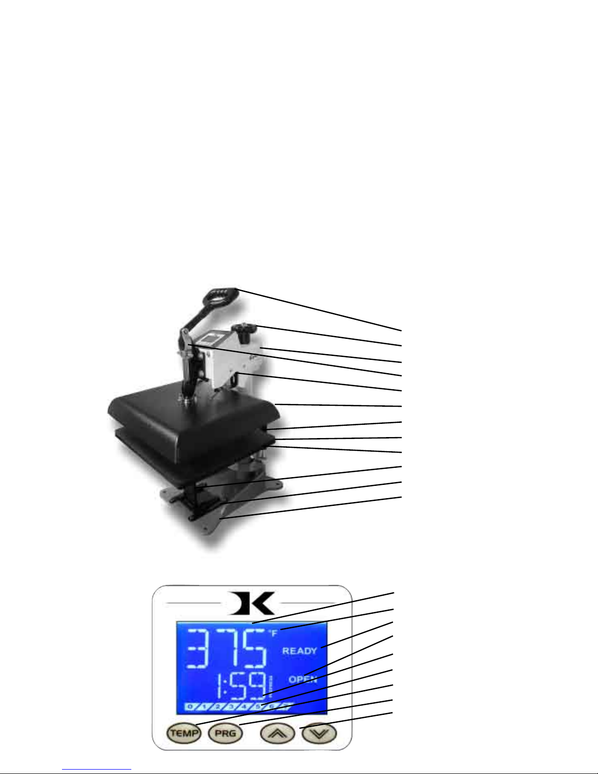
Throughout this manual, many areas and components of this machine
will be referred to by specic names. Please refer to the illustrations
below in order to become familiar with some of the terminology used
in this manual.
Handle
Pressure Knob
Top Head
Clamp/Linkage
Pwr Inlet/On-Off
Heat Platen
Stop Collar
Lower Table
Silicone Pad
Pedestal
Gibb Plates
Base
Temperature
°F/°C Indicator
Ready/Heating Indicator
Open/Timing/Done Ind.
Time
Pressure Bar Graph
TEMP key
PRG key
Up/Down Arrow keys
Default Operating Mode of Controller
Page 4

4
Setup & Suggestions
• Locate the press on a rm, sturdy work surface. It is recommended but
not necessary to bolt the press to a workbench using the rear mounting
holes on the base frame.
• A stand on lockable casters is available from Geo Knight & Co or your
distributor.
• The height of the bench/work space the press is located on would be
ideally 25” to 30” high. The higher the press, the more difcult to
close/lock.
• Attach the power cord from the rear to the underside of the top head.
There is a power inlet under the top head that the modular cord will
plug into.
• It is HIGHLY RECOMMENDED that the cord be strapped or tied to
the back white post of the press, so that the cord is not pulled on and
tugged out of the power inlet where it plugs into the press. TEST and
make sure the cord travels freely when swinging the press, and that
there is no tension or pulling on the inlet socket where the power cord
plugs into the head. Make sure the cord can not be pressed by the
heater.
• The press should remain in the unclamped OPEN position when not in
use. Do not leave the heater block closed on the table when not using,
unless transporting.
• The top head should be swung over the pressing table when not in
use. Do not leave the platen down on the silicone pad when heating.
Always leave the heat platen in the UP position.
Page 5
5
Normal Operation
Normal Operating Mode
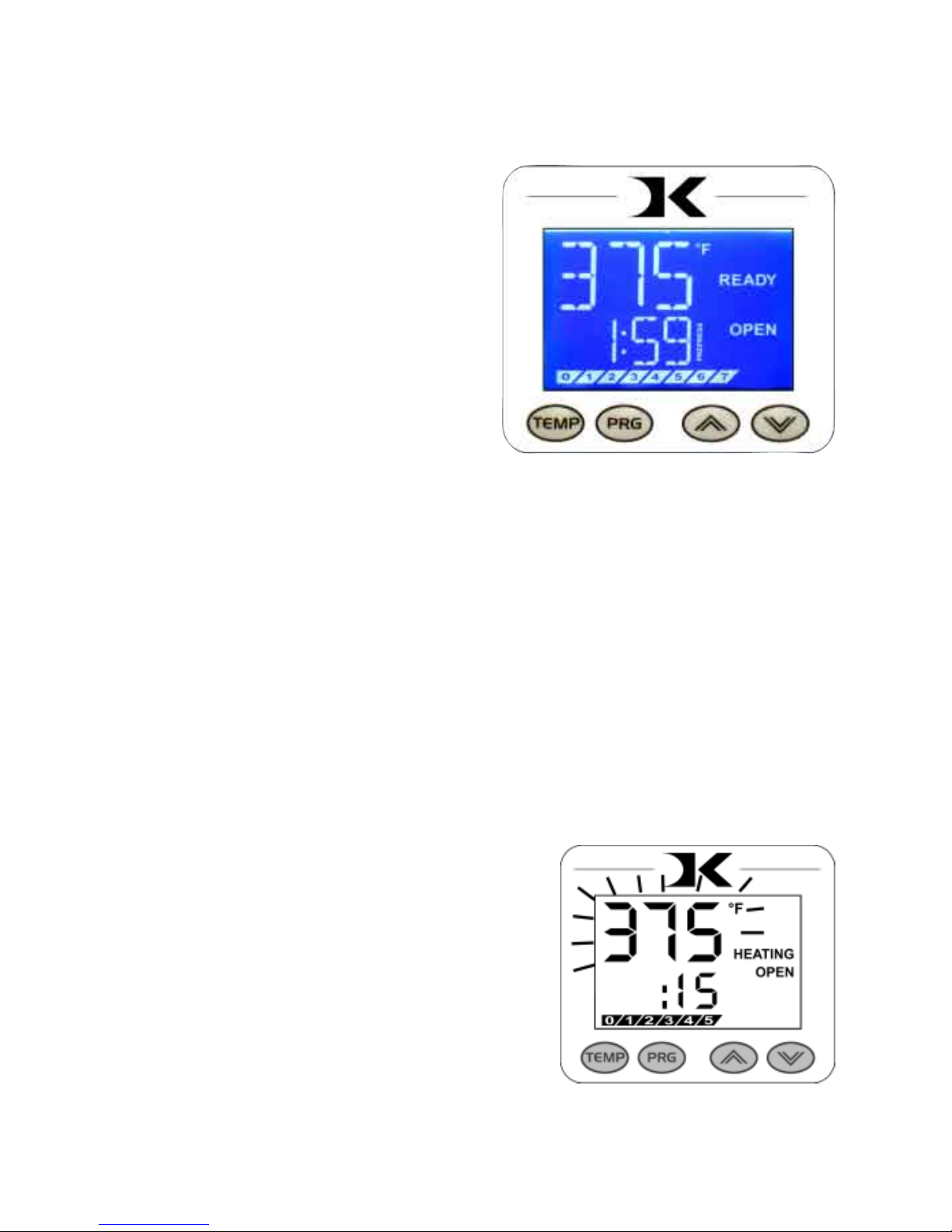
The normal operating mode of
the press will display the current
actual Temperature at the top of
the screen and the time setting
or elapsed time below the
temperature.
The right side the screen will
indicate the heating status by
stating HEATING, READY, both
of those words, or none at all,
depending on if it is cooling down or heating up to the set temperature.
READY is shown only if the current temperature is within 5 degrees of
the set point temperature.
The right side of the screen will also indicate the timing status by stating
OPEN, TIMING or DONE. The DONE indicator may remain on in
some cases until the press is opened back up.
If the pressure feature is enabled, the pressure bar graph will show the
last known pressure exerted when the press was closed.
Setting Temperature
From the normal operating mode,
simply press the TEMP key to set the
temperature.
The ashing 3-digit number is the
temperature setting (not the actual
current temp). Use the Arrow Keys to
set the desired temperature. Hold them
down to increase rapidly, press both
together to set it to 350°F.
Press TEMP again to lock in the setting.
Page 6
6
Setting Time
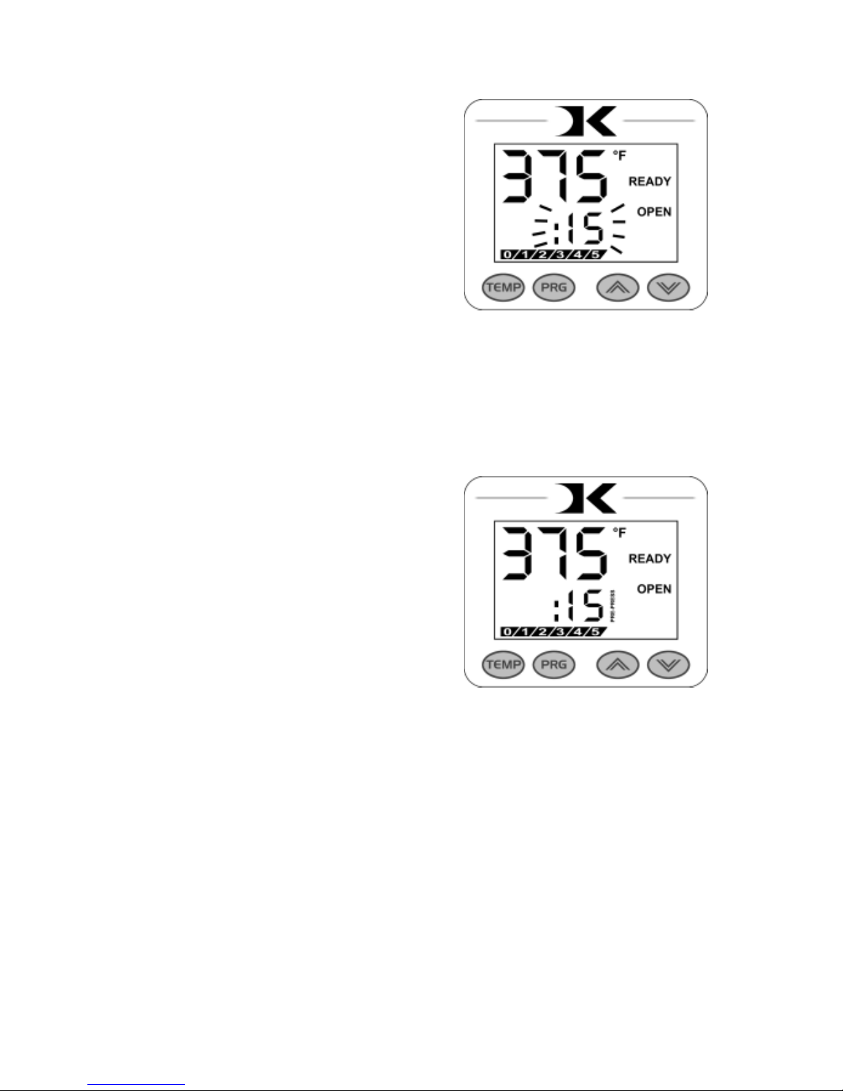
From the normal operating mode, simply
use the Arrow Keys ONLY to set the
time. Do not touch the PRG key.
Hold down either the Up or Down arrow
key for more than 2 seconds and the time
will increase rapidly.
Press BOTH Arrow Keys and the time
will reset to 00 seconds.
Pre-Press Timer
There is a second timer available for
use, called the “Pre-Press Timer”.
This feature is useful if a multiple-step
process is performed.
For example: If a product must be
pre-pressed for 5 seconds before a
main pressing cycle of 20 seconds, the
Prepress timer can be set for 5 secs, and
the main timer for 20. When the operator closes the press, the 5-sec
time counts down. When the operator opens the press, the time setting
switches to 20 seconds.
The word PREPRESS will be displayed next to the pre-press time setting
when it is active. To set the pre-press time, simply use the Arrow Keys
to set the time. If PREPRESS is not displayed next to the time, quickly
close and then open the press to switch to the prepress time.
To turn ON the prepress timer feature, enter the User Options Menus
(see page 18) and go to the PPR setting and turn it ON. (see page 22)
Page 7
7
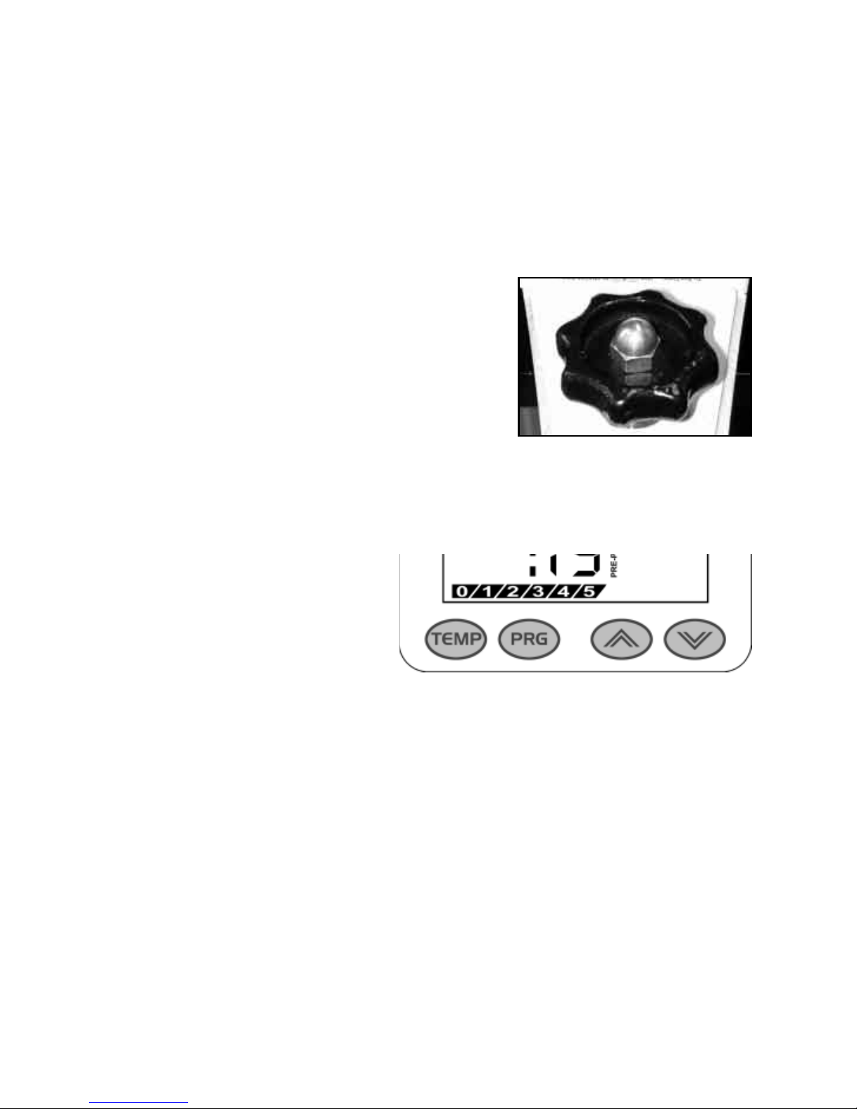
The Digital Pressure Bar
Graph indicates a basic 0-9
scale of pressure exerted.
The pressure bar graph
resets when the press is
closed/locked while timing.
If the pressure adjustment has been changed, or a different thickness
item has been placed in the press, the pressure bar graph will not change
until the press is closed and locked and the timer is counting.
This bar graph is directly related to the amount of pressure, or resistance,
being felt and applied to the bottom table. If a thicker item is placed in
the press, and no adjustments are made to the pressure knob, then the
amount of pressure clamping down will be greater, and the bar graph
will show a higher number. Here are some bar graph guidelines:
A very light pressure slight clamping would be in the 0 to 3 range.
A good medium pressure for most applications would be 4 to 6.
Excessively high pressure for demanding items would be 7-9.
Pressure is set manually using the large black Pressure Adjustment
Knob. There is one important rule of thumb when setting pressure: The
press MUST LOCK IN PLACE when lowering and clamping the press.
Do not simply let the platen rest on the pad. A good solid two-handed
locking force is recommended when rst doing transfers to insure good
results. A “Ka-Thunk” click/clamp sound will result when locking the
press in place.
• To decrease the pressure, turn the
pressure knob to the left, counterclockwise.
The top head will rise away from the lower
table.
• To increase the pressure, turn the
pressure knob to the right, clockwise. The
top head will lower toward the pressing table.
Setting Pressure
Digital Pressure Bar Graph
Page 8

8
Guidelines & Standard Settings
The following information covers some basic guidelines for pressing,
as well as some generic parameters for basic heat transfer applications.
• When pressing shirts, it is often recommended that the shirts be quickly
pressed for 2 to 4 seconds before transferring to remove wrinkles and water
content.
• When pressing two sides of a garment, pull the garment over the table so
that the printed side drapes underneath the table. This will avoid reheating
previously transferred designs on opposite sides of garments. It will also
avoid any bleed-through of inks on lighter fabrics.
• Avoid laying collars, cuffs, zippers, and other bulky parts of garments
on the lower table, as these can adversely affect pressing conditions, and
reduce the life of the silicone pad.
• When pressing rigid substrates (plastics, metals, woods, etc.), be sure that
any protective lms or laminates are removed before heating.
• Always check that the transfer image is face down against the material, to
avoid sealing the image against the heat platen instead of the substrate.
Always follow the transfer media suppliers instructions when
pressing. The information below is for general reference only, and may
not be as accurate as the instructions provided by the transfer media &
imprintable substrate supplier.
• Hot Split Supplier Transfers 350-375°F, 8-10 secs
• Puff Transfers 350-375°, 5-7 secs (extra heavy pressure)
• Ink-Jet Transfer Papers 360°, 15-18 secs
• ColorCopy/Laser Transfer Papers 375°, 20-25 secs
• Sublimation Inks (Polyester Fabrics) 400°, 35 secs
• Sublimation Inks (Plastics) 400°, 1 min, 15 secs
• Sublimation Inks (Metals) 400°, 1 min
• Sublimation Inks (Woods) 400°, 1 min, 15 secs
• Sublimation Inks (Ceramics) 400°, 4 min
Page 9
9
ERR Mode
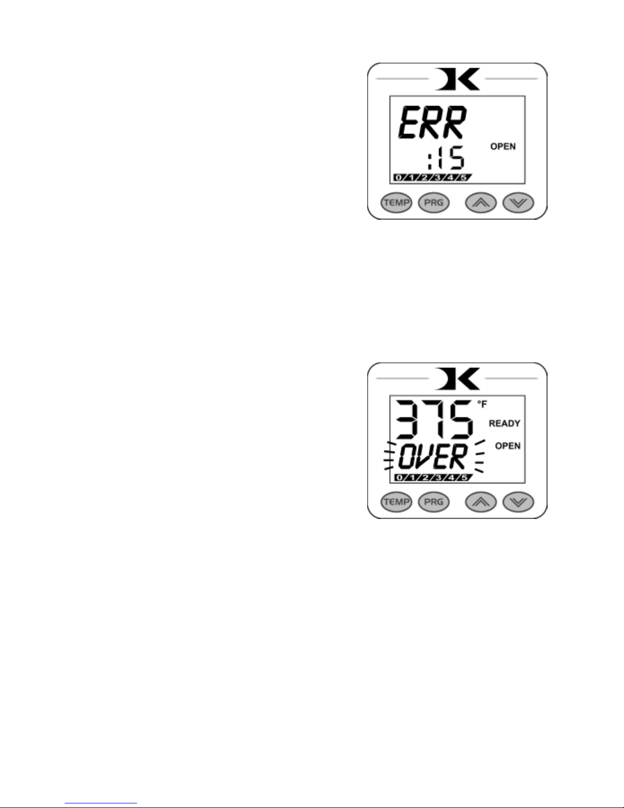
During operation of the press, if there
is a loss of signal from the temperature
sensor wire, the ERR display will
appear.
This is a safety feature that will shut off
the relay so the press will not overheat
aimlessly without a temperature signal.
Once the temperature signal is restored (no longer broken, or plugged
back into the control) the press will resume the temperature display, and
start heating if necessary. If ERR persists, contact support.
Over-Temp Alarm
If the press heats beyond the set
temperature by 40 degrees or greater,
the OverTemp alarm will sound.
This is a safety feature that warns the
operator of a possible thermal run-away
of the press. This means the press relay
may be locked in a heating position
where it will never stop heating, to a
possibly harmful temperature level.
If the OverTemp alarm sounds, set the temperature to a higher value
than the current actual temp. Wait 30 seconds and then reset the press to
your desired temperature and Watch Carefully. Do not let the press rise
to extremely high temps.
If it continues to rise, turn off the press and let it cool off to room
temperature. Turn the power back on and immediately set the temperature
to a low setting like 200°F. Wait for the press to heat up. When the press
displays “READY”, monitor the temperature and see if it continues to
heat to a level that the OverTemp alarm activates again. If so, contact
the factory.
Page 10
10
The main feature that makes the Digital Combo so versatile is the
interchangeability of the heat platens. Because the heat platens are
modular in their method of connection, one platen can be unplugged
and another attached, in its place. These platens are “Hot Swappable”.
You do not need to wait for the platens to cool off to remove.
The following instructions apply to the 14x16, 12x14, cap, plate & mug
heat platen attachments. All of them disconnect and connect in the same
manner.
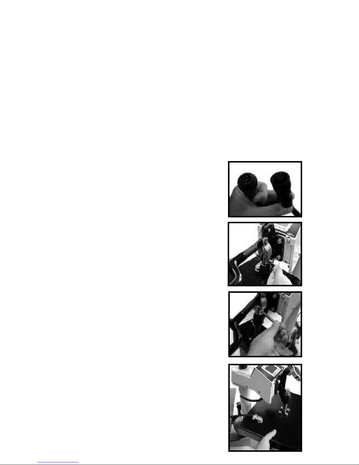
The heat platen can be safely disconnected with
the machine on. However, thermal gloves or
oven mitts must be used when handling hot heat
platens.
• Unplug the modular connector. This is done
by unscrewing the safety lock and pulling the
connectors apart.
• Lower the heat platen so it rests on the bottom
table, and do not clamp it.
• Pull out the quick release pin from the linkage.
It is easiest to remove when there is no pressure
on the side links or on the heat platen shaft.
• Once the quick release pin is removed, lift the
handle away, exposing the heat platen shaft now
disconnected from the linkage.
• Lift up on the heat platen slightly, enough to swing
it out away from the bottom table. Lower the heat
platen down and out of the clamp linkage.
Using Attachments
Removing a Heat Platen
Page 11
11
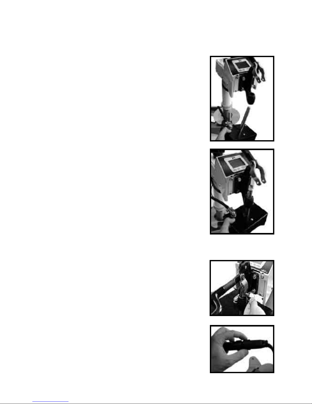
The heat platen can be safely connected with the machine on. However,
thermal gloves or oven mitts must be used when handling hot heat
platens.
• Lift the heat platen into the clamp linkage. Make
sure the rear guide fork holds onto the guide pin
in the back post of the frame. This holds the heat
platen in a straight position and keeps it from
rotating.
• Reattach the quick release pin through the linkage
and the heat platen shaft.
• Reconnect the modular connector. An Err display
might read on the controller if in the Normal
operating mode. If it does not read a temperature
after the heat platen is reconnected, turn the
machine off and then on again.
Attaching a heat platen
Page 12
12
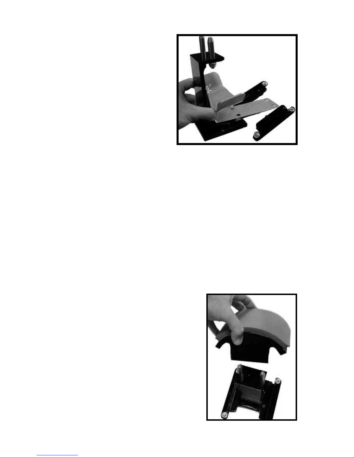
There is a curved 1/2-moon cap
holddown device for stretching the
cap over the curved bottom table.
Simply pull the back strap of the
cap behind the pedestal and under
the 1/2-moon shaped bracket. This
will hold the cap in place for proper
printing.
Cap Hold-down Device (For Cap Attachment Only)
The table can be easily adjusted in a straight position if the heat platen
does not correctly line up with the pressing surface. The pedestal the
table rests on can slide front to back on the base of the machine. Loosen
the screw in the gibb plates that holds the pedestal in place in order to
adjust its position.
The pedestal can also be slightly rotated in order to align with the upper
platen. Loosen all (4) screws holding the gibb plates in place, position/
rotate the pedestal to the desired place, and retighten the gibb plates.
Aligning the Pedestal
The standard tables included with the DK7
or DK8 will accommodate most items.
However there are other sized bottom
tables that are instantly interchangeable.
For the DK7, there are 3 different curved
forms (the top heat platen stays the same).
The mid-sized and youth-sized forms
are not included with the press. The midsized “EURO” form is especially useful
for solving wrinkling of caps in the middle
area for lower-prole tight-t caps.
Custom pedestals, bottom tables, and other
custom solutions are also available from the factory.
Optional Forms / Custom Pedestals
Page 13
13
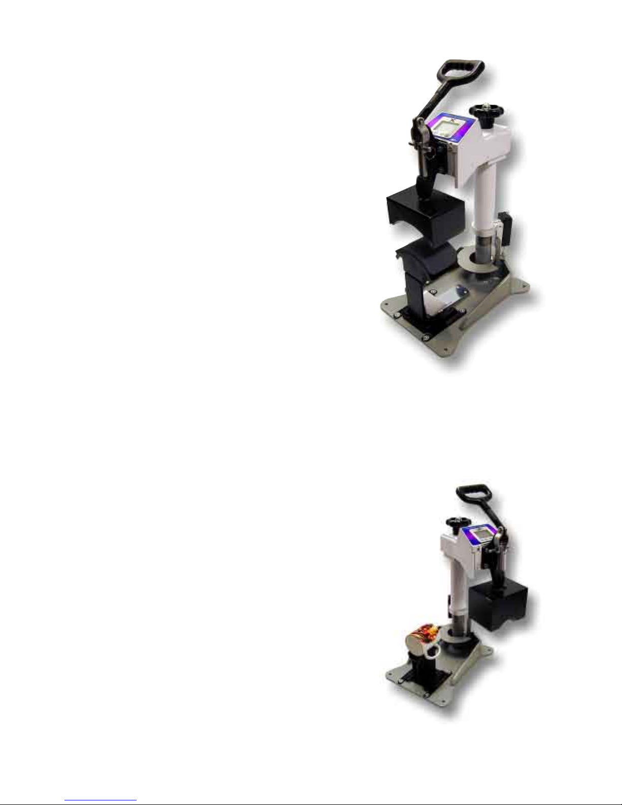
The cap attachment works the same as a
cap press. The only difference is that the
swing-away style Digital Combo press
allows complete access to the cap when
the heat platen is swung out, as opposed to
typical stand-alone clamshell cap presses.
Here are some tips for using the cap
attachment:
Make sure the cap holddown device is
attached to the bottom pedestal.
Make sure the proper bottom form is used.
If wrinkling/folding of the middle of the
cap occurs, this is a good indication that
the wrong form is being used.
Make sure the lower pedestal is adjusted and slid forward or backward
to line up with the heat platen above.
How to use the Cap Attachment
How to use the Mug Attachment
The mug attachment will print one half side
of the mug in one pressing cycle. Here are
some tips for using the mug attachment:
Use the Additional 1/8” Green Square Pad
for smaller 11 oz mugs. Lay the pad on top
of the transfer paper, then press.
Wider “steins” and 15oz mugs do not use
the extra pad. The heater is sized for larger
diameter mugs.
Sublimation transfers can be left on the
mug, and the mug can be ipped and
pressed on the opposite side for a continuous full wrap-around print.
Page 14
14
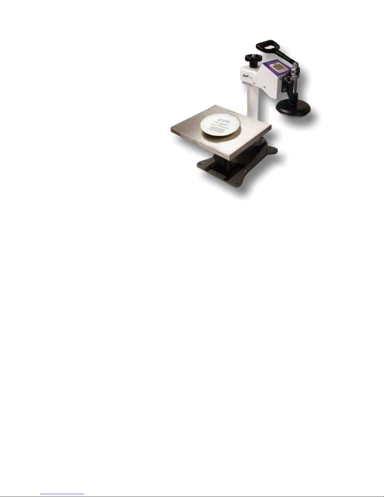
The plate attachment allows
the operator to press down
inside a dish or other indented
object. Here are some tips for
using the plate attachment:
Use the large T-Shirt at
bottom table.
Place the 3-sided aluminum
tray on top of the T-Shirt
table. This will protect the
main T-Shirt silicone pad
from being cut into by the
plate’s bottom edges.
Plate the black circular silicone pad on the tray. Center the pad so that
it is directly underneath the plate heater block attachment when swung
over. Make sure it lines up directly under the plate heat platen. Then
peel the backing off the circular black silicone pad and permanently
stick it to the tray.
The purpose of the black circular pad is to automatically center the plate
under the heat platen. It also provides cushioning when pressing plates.
Set the clamping pressure of the press so the black pad is compressed to
50% its height. Pressing heavier may risk breaking certain fragile style
plates.
Lay the 1/8” green circular pad on top of the transfer paper in the plate.
How to use the Plate Attachment
Pressing Ceramic Tile
To press ceramic tile, use the standard T-Shirt heat platen and bottom
table. Lay the 1/2” White Nomex Felt padding on top of the black
silicone pad. Then lay the transfer paper face-up, and the tile face-down
into the image. Press the tile from the back side, rmly. This wraps the
transfer paper nicely around the radius of the tile.
Page 15
15
Loading a Preset
Programmable Presets
How Presets Work
There are 70 programmable presets in the controller. The operator can
store a Temperature, Time, Prepress Time, and Pressure setting in each
preset.
When a preset program is loaded by the operator, the Current Temperature
Setting, Time and Prepress Settings (if there is a Prepress setting in that
preset) are updated in the normal operating mode.
The pressure is NOT set for the operator mechanically. A brief display
of the pressure value in the preset is shown while updating the current
settings. This is simply a reference... a reminder of what pressure setting
the operator must adjust for that preset.
There are 2 main functions to using the presets. LOADING and EDITING
the preset. LOADING a preset simply means selecting a desired preset,
and returning to the normal operating mode where the current settings
are changed. EDITING a preset is when the operator actually changes
the preset’s settings.
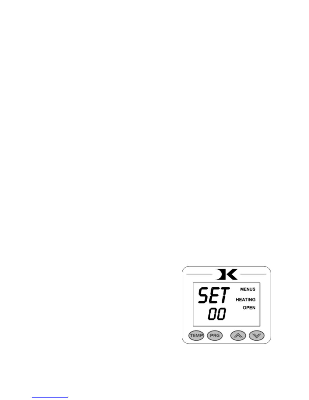
To enter the presets, press the PRG
key.
SET will display on the screen.
Use the Arrow Keys to select a preset
from 00 to 70.
Press PRG to return to the normal
operating mode. The current active Temperature, Time & Prepress time
settings (if there is a prepress setting in that preset) are now updated
with the presets values.
Page 16
16
Editing/Programming a Preset
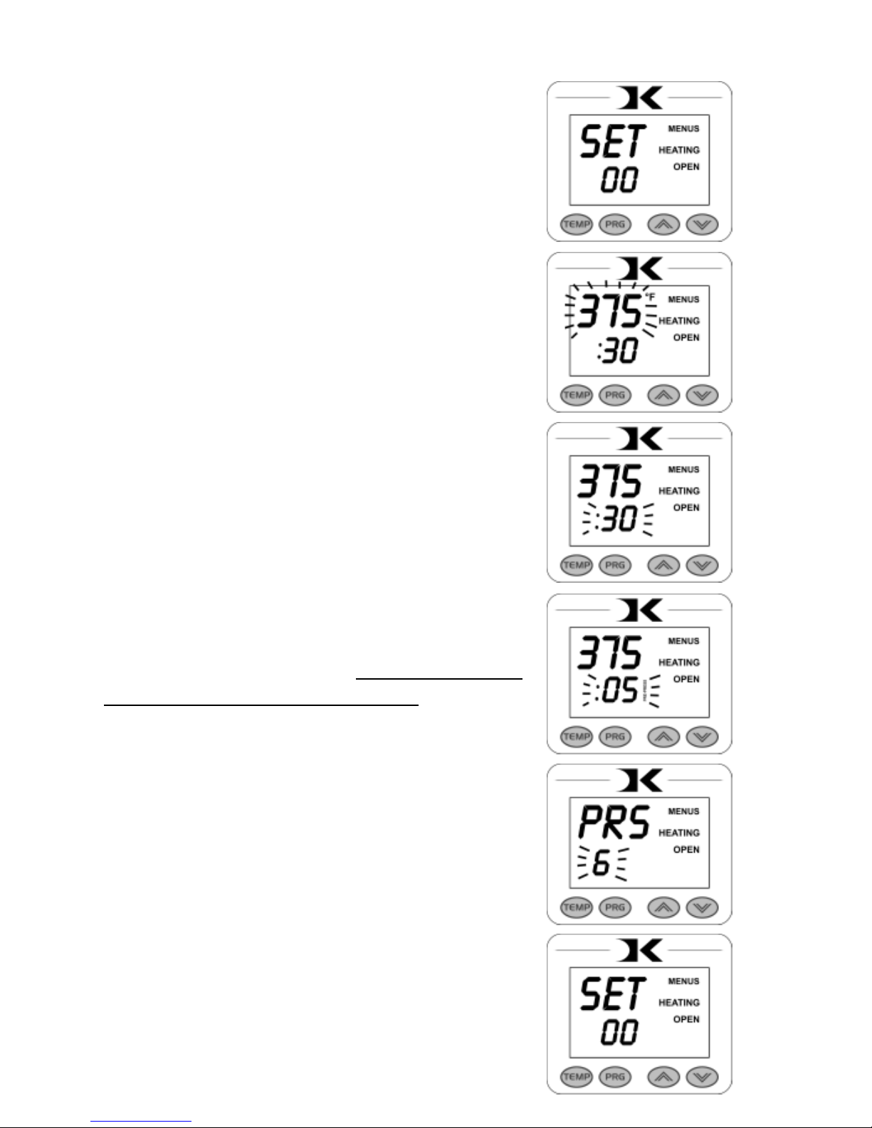
To edit a preset and change it’s values to your
own desired settings, you simply use the TEMP
key while in the SET preset mode.
From the normal operating mode, press the PRG
key. SET displays on the screen. Use the Arrow
Keys to select the preset # you wish to edit.
Press the TEMP key. The temperature will ash.
Use the Arrow Keys to set the temperature for
that preset.
Press the TEMP key. The time will ash. Use
the Arrow Keys to set the time for that preset.
Press the TEMP key. The Prepress time will
ash. Use the Arrow Keys to set the Prepress
time. Set the Prepress time to 00 if only one timer
is to be used for that preset. Setting Prepress to
00 will disable the Prepress feature.
Press the TEMP key. The Pressure reference
value will ash. Use the Arrow Keys to set the
pressure for that preset. This will display 0 to 9
for presses congured for Bar Graph Pressure
readout, and will display 0:00 to 10:00 for
presses congured for a Height Gauge readout.
Press the TEMP key. The screen returns to the
preset #. Press PRG to return to the normal
operating mode, or use the Arrow Keys to select
a different preset and edit that as well.
Page 17

17
A Walkthrough Tutorial for using Presets
Here is a tutorial of programming 2 different presets, and then an
example of using them in normal daily operations. Do this walkthrough
to practice using presets.
Part 1: Programming 2 different presets.
From the normal operating mode, press PRG. SET appears.
Use the arrow keys to select SET 01.
Press TEMP. Set the ashing temperature to 400 with the arrow keys.
Press TEMP. Set the ashing time to 45 with the arrow keys.
Press TEMP. Set the ashing Prepress time to 00 with the arrow keys.
Press TEMP. Set the ashing Pressure ref to 6 with the arrow keys.
Press TEMP. Use the arrow keys to select SET 02.
Press TEMP. Set the ashing temperature to 350 with the arrow keys.
Press TEMP. Set the ashing time to 12 with the arrow keys.
Press TEMP. Set the ashing Prepress time to 3 with the arrow keys.
Press TEMP. Set the ashing Pressure ref to 8 with the arrow keys.
Press TEMP. Press PRG to leave the preset mode.
Presets SET 01 and SET 02 have now been programmed.
Part 2: Loading the presets. Let’s say we are powering on the machine
and starting a job. The rst job will need to use preset 01, and later on
the next job will need preset 02.
From the normal operating mode, press PRG. SET appears.
Use the arrow keys to select SET 01 then Press PRG. Done!
The press is now set for 400°F and 45 seconds and will start to heat to
that temperature. When leaving the presets, the screen briey displayed
PRS 6 - indicating you must manually set the clamping pressure so the
bar graph shows 6 (or close to it) at the bottom of the screen.
Now let’s change to the next job. Press PRG. SET appears.
Use the arrow keys to select SET 02 then Press PRG. Done!
The press is now set for 350°F, 12 secs, 3 prepress, and you are reminded
to set the pressure heavier to 8 on the bar graph display (when closed).
That’s it! You can load a preset as often as needed: just press PRG, pick
the preset you want with the Arrow Keys, and press PRG again.
Page 18
18
User Menus
Entering the user menus & options
There are many useful features beyond simply setting time & temperature,
and storing presets. All of these additional features are available to the
operator in the User Menus.
To access the user menus, simply press TEMP & PRG at the same
time from the normal operating mode and let go.
(Try to use two hands and press the keys at the exact same time. If one
key is pressed too early from the other, the temperature setting or preset
modes may be activated instead. Turn the press off and then on and try
again.)
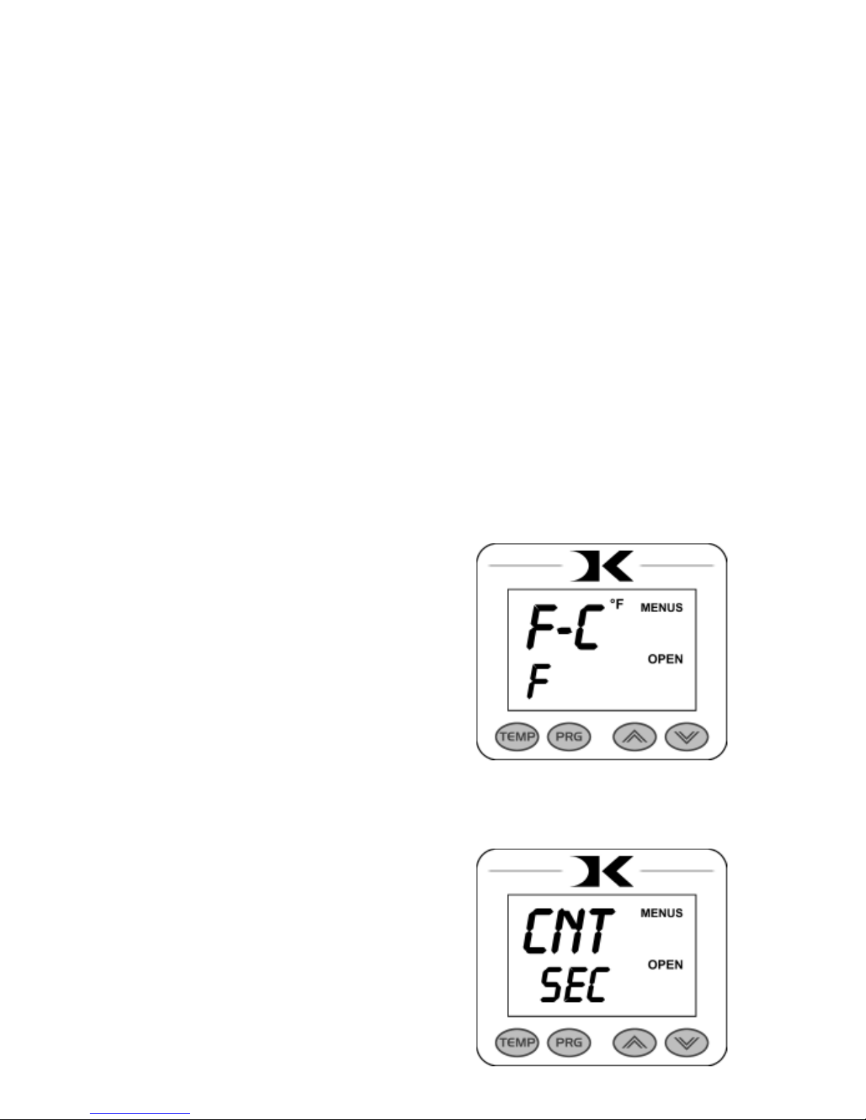
Fahrenheit / Celsius
The current and set temperature can be
displayed in °F or °C. After entering the
user menus (see above), use the arrow
keys to select F or C. Press PRG to move
to the next menu item.
Timer Counter Units
The timer and Prepress timer can be set
for mins/secs (default) or hours/mins. If
special applications need a higher timer
range than 99 mins, 59 secs, this can be
changed. After entering the user menus
(see top of page), Press PRG until CNT
displays. Use the arrow keys to select
SEC or HR. Press PRG to move to the
next menu item.
Page 19
19
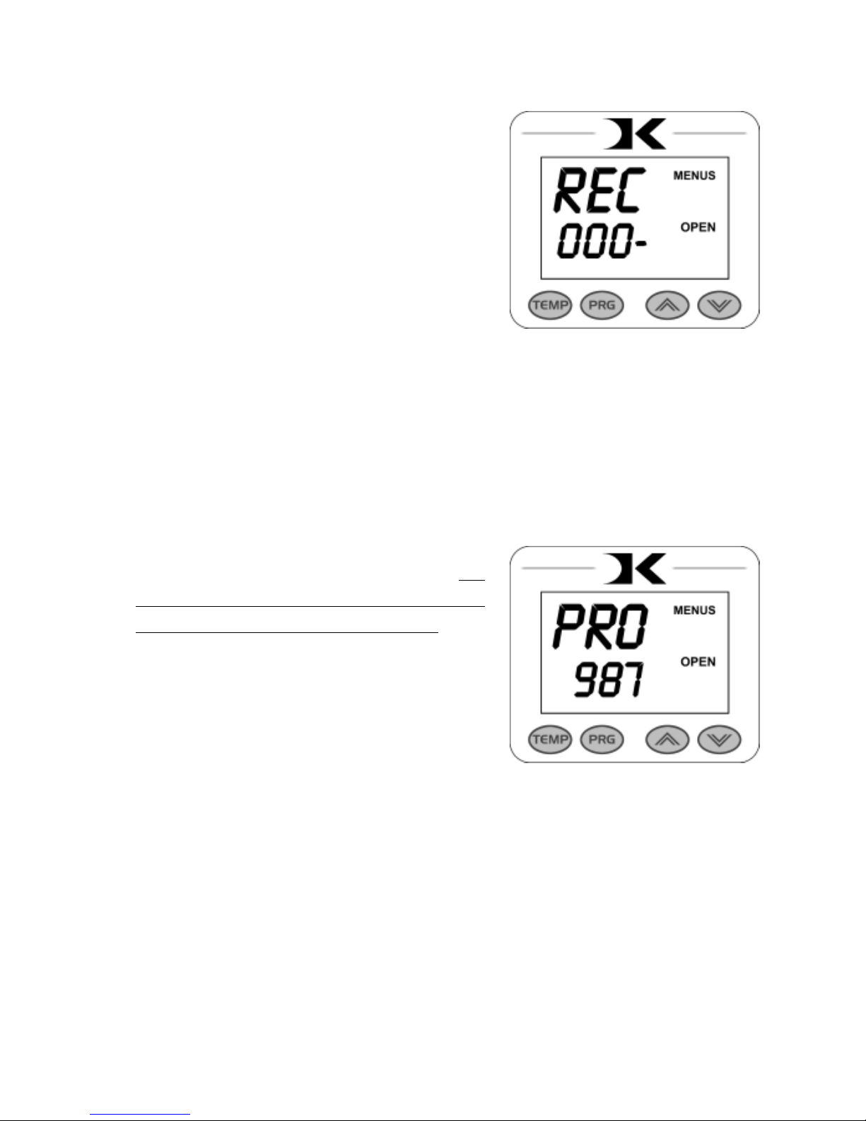
Recorded Pressings (User Odometer)
There is an “odometer” that records
pressing cycles done. This can be cleared
and reset to 0 at any time when needed.
The gure scrolls and it’s beginning and
end are separated by a “-” sign.
After entering the user menus (see
top of page 18), Press PRG until REC
displays. Use the arrow keys to reset the
counter to 0. Press PRG to move to the
next menu item.
Pressure Minimum
To reset and redene “0” for the pressure
bar graph, use this calibration menu. Do
NOT adjust this setting unless you are
sure adjustments are necessary.
Adjust the pressure of the machine so
there is barely any locking pressure
when clamping and locking the press.
Press either Arrow Key. The press now
considers this pressure as “0” on the
Pressure Bar Graph Display.
Press PRG to move to the next menu item.
Page 20
20
Pressure Maximum
To reset and redene “9” for the pressure
bar graph, use this calibration menu. Do
NOT adjust this setting unless you are
sure adjustments are necessary.
Adjust the pressure of the machine
so there is extremely heavy pressure
when clamping and locking the press.
Press either Arrow Key. The press now
considers this pressure as “9” on the
Pressure Bar Graph Display.
Press PRG to move to the next menu item.
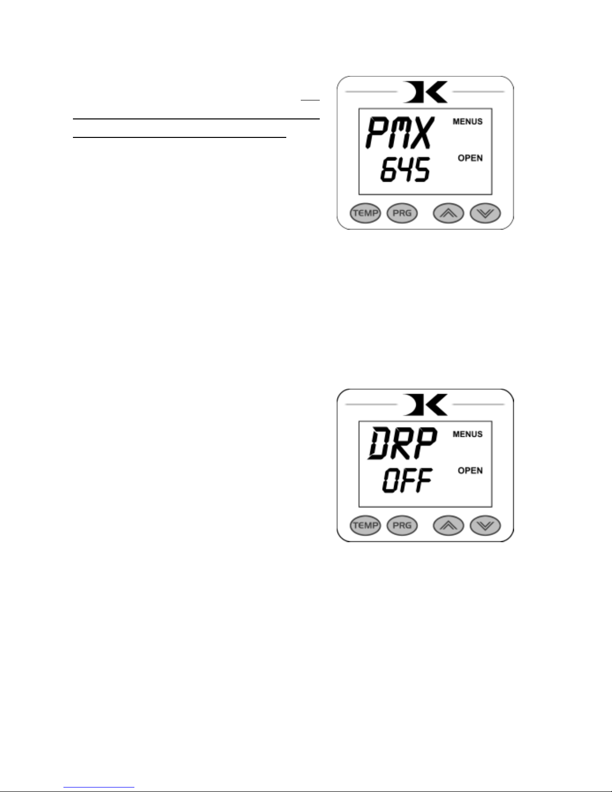
Temperature Drop Sense
The press can be set to alarm if the
temperature drops a certain range below
the set temperature. This is useful to
warn the operator if the press is too
far out of temperature range during
excessive use.
After entering the user menus (see top of
page 18), Press PRG until DRP displays.
Use the arrow keys to set it to OFF (default), or 10, 20, 30, etc.
If the current temperature drops below the set temperature by that many
degrees, and alarm will sound. Press TEMP to silence the alarm.
Press PRG to move to the next menu item.
Page 21
21
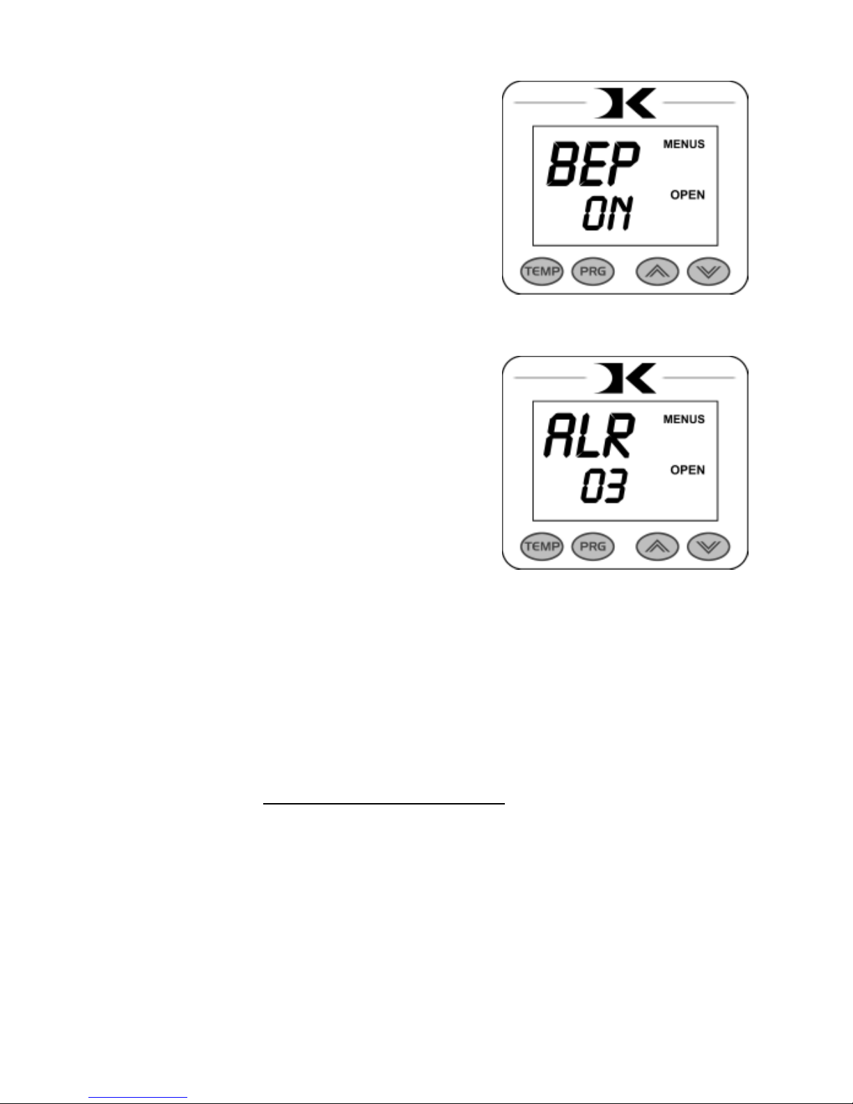
Keypad Beeper
The keypad beep can be silenced if
needed. After entering the user menus
(see top of page 18), Press PRG until
BEP displays. Use the arrow keys to set
it to ON or OFF.
Press PRG to move to the next menu
item.
Alarms
The timer alarm can be adjusted for
different beeping patterns. This can
differentiate between multiple presses,
and allow the operator to have a short
beep or a continuously repeating beep.
After entering the user menus (see
top of page 18), Press PRG until ALR
displays. Use the arrow keys to set it to
OFF, or 1 through 10.
Press PRG to move to the next menu item.
• denotes a short beep.
_ denotes a longer beep.
~ denotes innite loop.
Alarm # Alarm Pattern
Off No alarm
01 • • • _
02 • • • _ ~
03 • • _
04 • • _ ~
05 • • •
06 • • • ~
07 _ ~
08 _
09 •
10 • (shorter)
Page 22
22
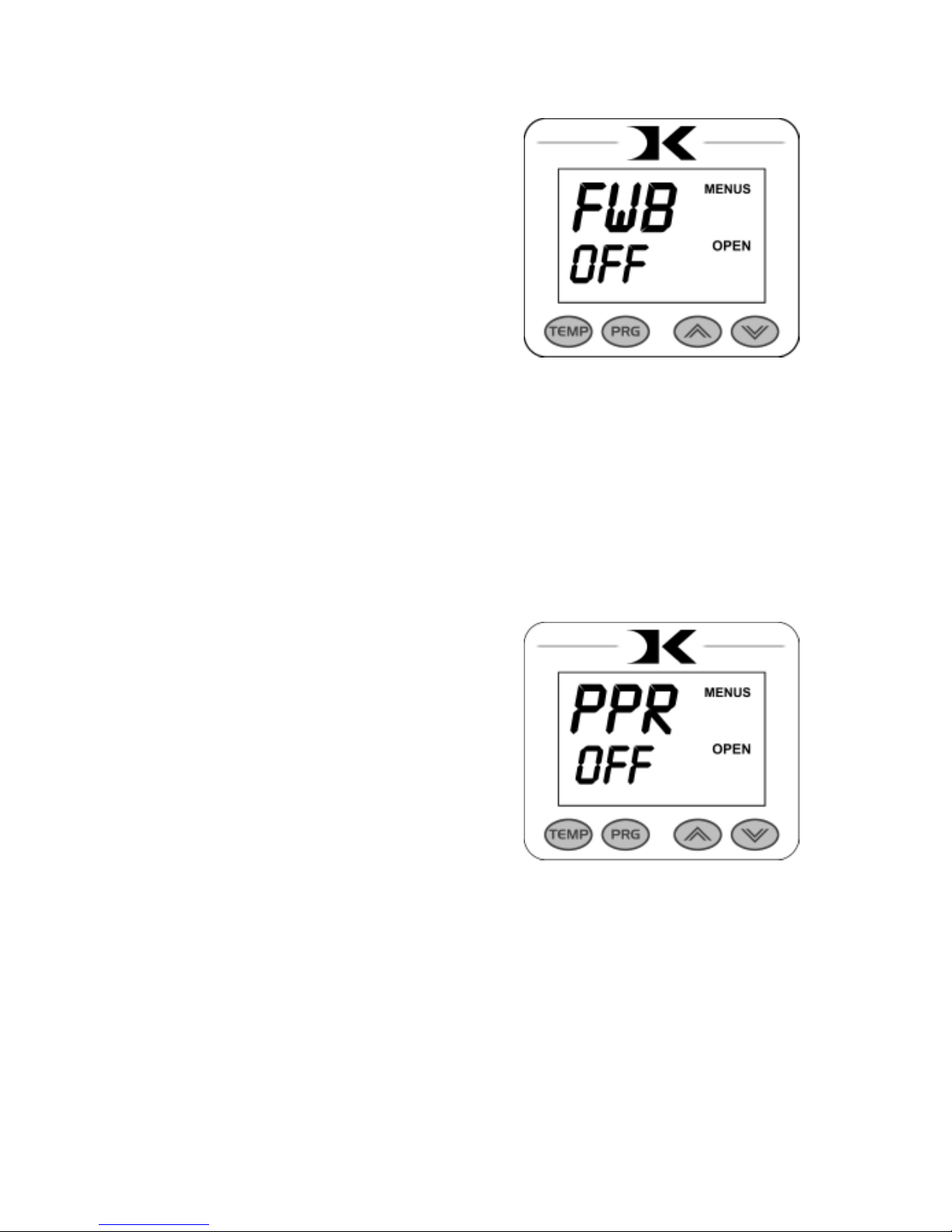
Finished Warning Beep
The press can sound a beep on the last
3 seconds of the timer or Prepress timer
countdown. This is useful if the press
is automatic and the operator needs a
warning that the press is about to nish,
open, or pop-up dramatically.
After entering the user menus (see top
of page 18), Press PRG until FWB
displays. Use the arrow keys to set it to
ON or OFF.
Press PRG to move to the next menu item.
Prepress Timer
The press can cycle back and forth
between two distinct timer settings:
the normal countdown timer, and a 2nd
Prepress timer. (see page 6). This menu
item turns the Prepress timer ON or
OFF.
After entering the user menus (see top of
page 18), Press PRG until PPR displays.
Use the arrow keys to set it to ON or
OFF.
If PPR is set to OFF, pressing PRG will return to the normal operating
mode.
If PPR is set to ON, pressing PRG will move to the next menu item.
Page 23
23
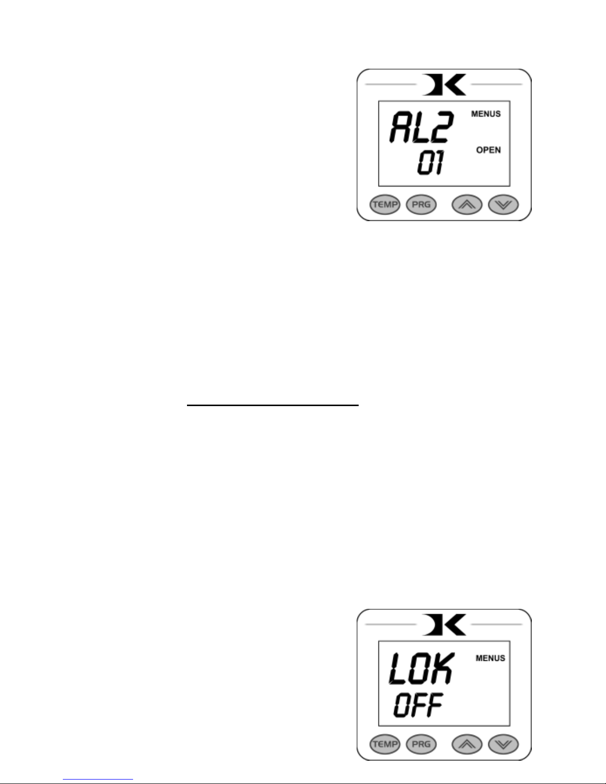
Prepress Alarms
The Prepress timer alarm can be
adjusted for different beeping patterns.
This allows for differentiating from the
normal timer, and can allow the operator
to have a short beep or a continuously
repeating beep.
After entering the user menus (see top of
page 18), Press PRG until AL2 displays.
The PPR menu must be set to ON for this menu to be visible. Use the
arrow keys to set AL2 to OFF, or 1 through 10.
Press PRG to move to the next menu item.
• denotes a short beep.
_ denotes a longer beep.
~ denotes innite loop.
Alarm # Alarm Pattern
Off No alarm
01 • • • _
02 • • • _ ~
03 • • _
04 • • _ ~
05 • • •
06 • • • ~
07 _ ~
08 _
09 •
10 • (shorter)
Operator Lockout
An operator lockout feature is available
to the owner of the press. This prevents
the average user from changing any
settings or adjusting anything on the
controller.
Contact the factory for instructions on
using this feature.
Page 24
24
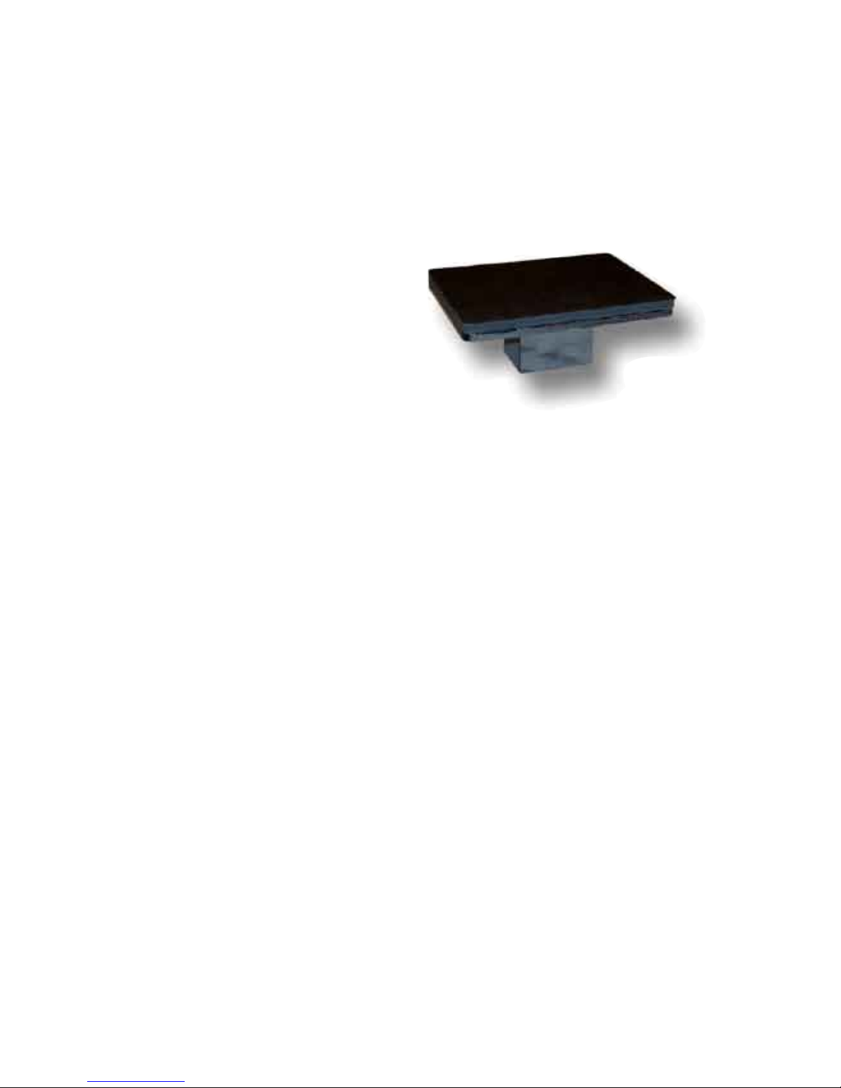
The lower table on the machine is interchangeable. Different sized
optional tables can be obtained for various materials & handling
requirements.
The tables simply t right onto the
bottom pedestal. There are two steel
pins that look like “bullets” that t
into the two corresponding holes
in the bottom tables. They may be
tight from the factory, and can be
reamed out to allow for a looser t
and faster change-out.
Custom lower tables and pedestals are available from the factory for
specic needs. Tongue-style pedestals with the support at the rear are
often requested for pocket/bag loading applications. These “divingboard” anvil style pedestals are especially helpful with hard-to-load
applications.
Interchangeable Tables
Maintenance
The majority of the press has been designed to be as maintenance free
as possible. There are only a few aspects of the machine that should be
monitored to insure proper operation.
• The clamp/linkage assembly is the greatest area of wear and friction on the
press. The post that connects to the heat platen should be lubricated with
SuperLube - a clear high-temperature lubricant.
• If the pins in the clamping mechanism wear, or the holes become elongated,
eventually the press will not lock properly. This can be very detrimental
to pressing results & quality! Contact the factory for a very inexpensive
clamp replacement to get the clamps back to new condition.
• The silicone pad on the lower table can degrade after much use and over
an extended period of time. This pad is replaceable. If the pad becomes
dried out, cracked, or there are chunks removed from the silicone pad, this
can result in inconsistent and poor quality transfers.
Parts / Maintenance / Misc
Page 25

25
Replacement Parts
Here is a list of current replaceable parts on the DC16 Digital Combo as
of the writing of this manual:
MEN-DCCLP ...................DC CLAMP ASBLY W/HANDLE & PIN
DKA-CTRLC ...................DIGITAL KNIGHT PROCESSOR BOARD
DKA-CTRLP ...................DIGITAL KNIGHT POWER BOARD
ELN-KM0227A2 .............DIGITAL COMBO MEMBRANE KEYPAD
RPK-DKPWR ..................DK POWER INLET/SWITCH/CORD KIT
ELN-VS10N031C ............TIMER LEVER MICRO SWITCH
DC16-HBA120 ................DC16 14X16 HEATER BLOCK ASBLY 120V
RPK-DCPSKIT ................DC PRESSURE SENSOR KIT
CAN-DKKNOB ...............DK/DC BLACK KNOB
FAS-EM5818 ...................5/8-18 HEX ACORN NUT
MEN-DKPVBLT .............DK/DC PIVOT BOLT
FAS-NTA1018 .................THRUST BEARING (2 req)
MEN-TWB1018 ..............SMALL WASHER THRUST BEARING (4 req)
DCA-1416TBL ................DC 14 X 16 DROP-ON TABLE (w/ silicone pad)
SRM-381416 ....................3/8 X 14 X 16 SILICON SPONGE
RMN-½NOM1416 ...........½” X 14 X 16 WHITE NOMEX/HEAT FELT
DCA-BASE......................DC BOTTOM BASE W/POST
DKA-PEDESTAL ............DK/DC PEDESTAL W/ LOC POSTS
DKA-GIBB ......................DK/DC PEDESTAL SLIDE GIBB (2 req)
MEN-DCCLLR................DC STOP COLLAR
SHN-DCCVR ..................DC TOP CONTROL PANEL COVER
SHN-DC16HBC ..............DC16 14X16 HEATER BLOCK COVER
DCA-LRGPBSFT ............DC LARGE PRESSURE BLOCK & SHAFT
DCA-FEMHRN ...............DC TOP HEAD FEMALE WIRE HARNESS
DCA-MALEHRN ............DC HEAT PLATEN MALE WIRE HARNESS
ELN-MSTB2.5.................OST 5MM TRMNL THERMOCOUPLE PLUG
Page 26
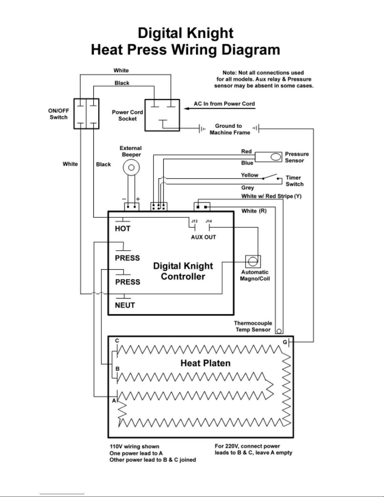
26
Wiring Diagram
Page 27

27
Troubleshooting
The following information attempts to address the most probable
mechanical and user issues with the press. Most issues with heat transfer
presses are application related. That is, they have to do with the results
of a particular transfer application.
For technical support on problems having to do with the nal results
of a particular transfer paper or media, please contact the supplier of
that transfer media. Generally, the machinery manufacturer is unable
to support the myriad of different transfer papers, inks and imprintable
items on the market from other resellers.
Q. The timer does not start when I close the heat platen, or the timer
does not reset when I open the press up.
A. There are several probable causes for this. The timer is activated
by a micro-switch under the head of the press. It is located on a sheet
metal bracket with slots. When the head of the machine is opened, the
timer’s lever should be depressed and the small contact button under
the lever should click in. The timer switch may need to be loosened and
moved along the bracket to a position that allows for the heat platen
cover to trigger the switch. The wires from the timer switch lead into the
head to a black plug plugging into the circuit board. Unplug this plug,
and make sure it is plugged back into ALL 6 gold pins on the circuit
board.
Q. The control displays Err when it rst comes on, and I can not set
the temperature or use the press.
A. The Err message will display if the heating signal from the platen
has been cut off, interrupted, or the heating sensor has failed. First check
the Lime Green temperature connector that plugs into the digital control.
At the top of the controller, there is a green connector that plugs in with
2 small wires. This is the temperature sensor wire. Check to make sure
is it properly seated. If after unplugging and plugging the lime green
connector the Err message still appears. unplug the green connector and
remove the 2 tiny wires from the lime green plug. Cut them back 1/4”
and strip them so they have new connections. Reconnect them to the
lime green plug so they are screwed in tightly and can not pull out. Plug
the green plug back in and turn the press on.
Page 28

28
Troubleshooting (cont.)
Q. I press the keys on the keypad, and there is no sound or response
from the controller.
A. Check the connection of the keypad to the controller. This is
inside the top panel. Unplug the power cord. Remove the two screws in
between the clamp/linkage that hold down the top panel, and carefully
lift the panel up and look inside at the digital controller. The keypad
connector passes in through the top panel. It should wind around the
rst circuit board and be seated fully into the connector. Check the
black keypad connector that plugs into the circuit board to see if it has
pulled apart. Also check the area where the keypad connects to the front
membrane to see if the leads have been damaged. The membrane keypad
may need to be replaced.
Q. The clamp becomes extremely difcult to open and close, and
sometimes binds up.
A. First, Loosen all 4 silver bolts holding the clamp on the head to
allow the press to re-center during use. Retighten after considerable use.
If this does not resolve it, the linkage pins and the posts that connect to the
heat platen must be lubricated with a clear, high temperature lubricant.
This type of lubricant can be obtained in any auto parts or hardware
store. Thoroughly clean the posts that come out of the heat platen, as
well as the pins. Relubricate the posts, pins, and all holes & areas in the
clamp assembly that receive motion. Then add new lubricant after all
moving parts are clean and dry.
Q. The press has shut off, and will not come back on after checking
the power cord.
A. Test for power coming from the back side of the power cord inlet
socket. Test for power coming from the back side of the on/off switch.
Test for power coming to the end of the black & white wires that come
from the on/off switch into the control board. This will narrow down
which power handling component needs replacement. RPK-DKPWR is
a common replacement kit that includes all these components.
Q. I pressed a transfer upside down. The inks and transfer material
have burned onto the heat platen.
A. Cool the press down. Using a nonabrasive detergent or cleaner,
thoroughly scrub the heat platen surface. Do not use an abrasive
scrubber, or a pad that will scratch the Teon coating of the platen. If
you are still unable to remove the transfer material, obtain teon heater
block cleaner from the factory.
Page 29

29
Geo Knight & Co Inc
52 Perkins St, Brockton MA 02302 USA
(508)588-0186 - Fax (508) 587-5108
[email protected] - www.heatpress.com
Geo Knight & Co warrants that the press is free from defects in both material and workmanship
One Year from the date of invoice to the buyer. If any parts or workmanship are found to be defective in
manufacture, Geo Knight & Co will repair or replace the defective parts or workmanship. In addition, Geo
Knight & Co warrants that the Digital Knight heat control is free from defects in both material & workmanship
and is covered under no-charge support for (3) years. Geo Knight & Co also warrants that the heating
element is warranted for the lifetime of the press, provided it is owned by the original purchaser. This lifetime
warranty on the heating element does not cover temperature sensor failure, damage or disconnection. This
warranty covers all parts to repair the defects, except when damage results from accident, alteration, misuse
or abuse, or when the machine has been improperly installed, or modied in any way. If the press becomes
defective during the limited warranty period of one year for the entire press, three years for the control, or
the lifetime of the heating element, Geo Knight & Co reserves the right to recall the defective press to the
factory for repairs if on site component replacement is deemed not possible by Geo Knight & Co. A return
authorization must be granted by Geo Knight & Co prior to its return.
If a press covered by the one year limited warranty must be returned to the factory for repairs,
Geo Knight & Co shall make every effort to repair buyer’s press. However, Geo Knight & Co reserves the
exclusive right to determine whether to repair or replace a defective press. If Geo Knight & Co authorizes a
replacement press, the warranty of the replacement press shall expire on the anniversary date of the original
machine’s invoice to the buyer.
There are no warranties which extend beyond the description on the face hereof. Seller disclaims
any implied warranty of merchantability and/or any implied warranty of tness for a particular purpose, and
buyer agrees that the goods are sold “as is”. Geo Knight & Co does not warrant that the functions of the
press will meet the buyers requirements or expectations. The entire risk as to use, quality and performance
of the press lies with the buyer. In no event will Geo Knight & Co be liable for any damages, including loss
of prots, destruction of goods or any other special, incidental, consequential or indirect damages arising
from the use of the press or accompanying materials. This limitation will apply even if Geo Knight & Co or
its authorized agent has been advised of the possibility of such damage.
Limited Warranty
 Loading...