

Digital China Networks DCWL-7962OT Installation Manual

DCWL-7962OT Out door AP Installation
Manual
DCWL-7962OT 室外型无线接入点产品
安装指导
Manual Version: v1.1

DCWL-7962OT Outdoor AP
Installation Manual Content
1
Content
CHAPTER 1 DEVICE INTRODUCTION.................................... 1-1
CHAPTER 2 PREPARATION FOR INSTALLATION ................ 2-1
2.1 INSTALLATION PRECAUTIONS ............................................................... 2-1
2.2 INSTALLATION ENVIRONMENT REQUIREMENTS ....................................... 2-1
2.3 EQUIPMENT ACCESSORIES ................................................................... 2-1
2.4 INSTALLATION TOOLS .......................................................................... 2-2
CHAPTER 3 AP INSTALLATION .............................................. 3-1
3.1 INSTALLATION PROCESS ...................................................................... 3-1
3.2 CHECKING BEFORE INSTALLATION ........................................................ 3-2
3.3 ENSURE THE INSTALLATION POSITION ................................................... 3-2
3.4 INSTALL DCWL-7962OT(R5) ............................................................. 3-2
3.4.1 Column Holding Installation ................................................................ 3-2
3.4.2 Wall Hanging Installation ..................................................................... 3-4
3.5 CONNECT CABLES .............................................................................. 3-6
3.5.1 Connect Network Cables ...................................................................... 3-6
3.5.2 Connect Ground Cables ....................................................................... 3-7
3.5.3 Connect RF Cables ............................................................................... 3-7
3.6 AP POWER ......................................................................................... 3-8
3.6.1 Checking before Power ........................................................................ 3-8
3.6.2 PoE Power ............................................................................................. 3-8
3.6.3 Checking after Power ........................................................................... 3-8
3.7 CONNECT AP TO INTERNET .................................................................. 3-8
DCWL-7962OT Outdoor AP
Installation Manual Chapter 1 Device Introduction
1-1
Chapter 1 Device Introduction
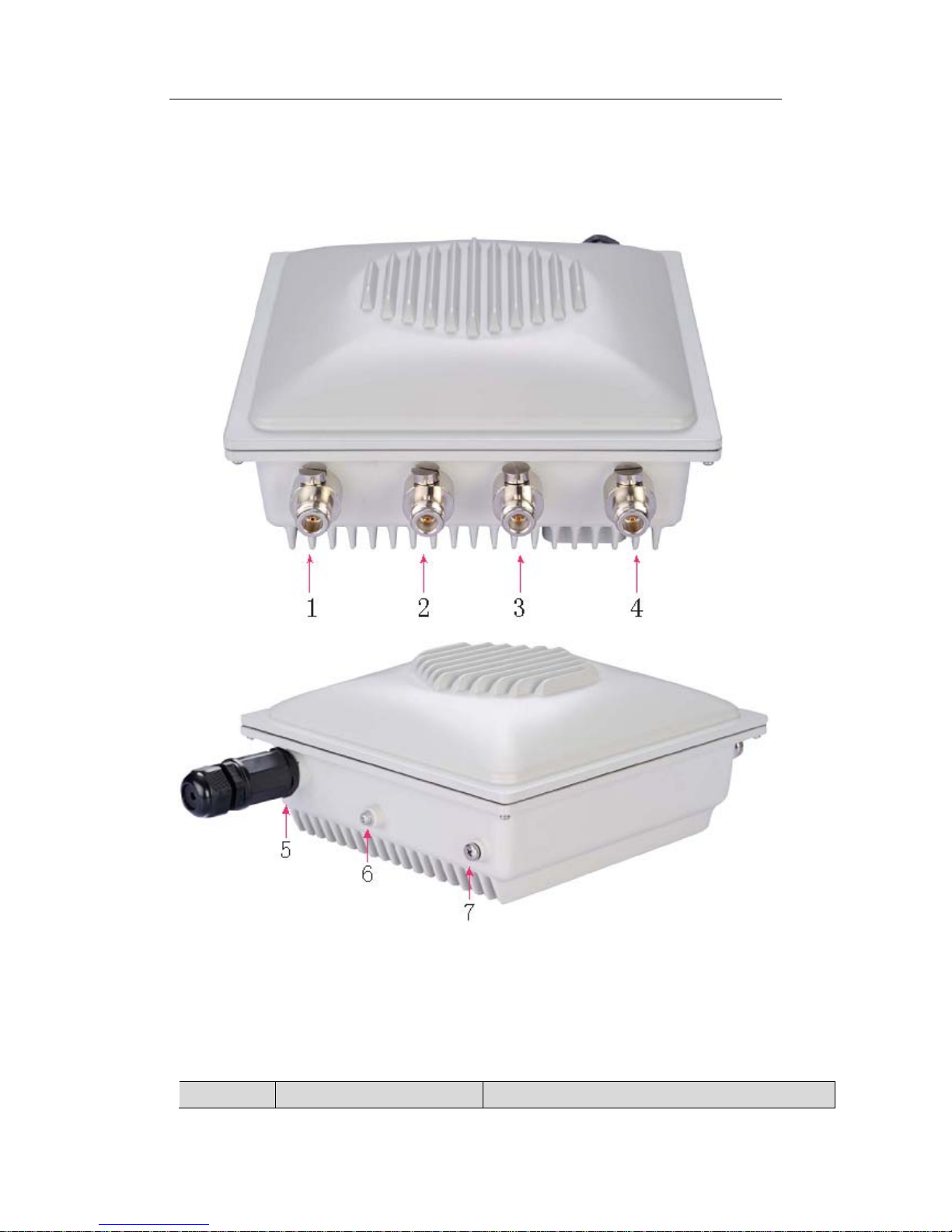
DCWL-7962OT(R5) outdoor AP is shown as below:
Fig 1-1 DCWL-7962OT(R5) AP
The ports explanation of DCWL-7962OT outdoor AP is as below:
Table 1-1 ports explanation
No.
Name
Explanation
DCWL-7962OT Outdoor AP
Installation Manual Chapter 1 Device Introduction
1-2
1
5G-1
5G
antenna
interface 1
2
5G-2
5G
antenna
interface 2
3
2.4G-1
2.4G
antenna
interface 1
4
2.4G-2
2.4G
antenna
interface 2
5
PoE
PoE interface, PoE power and Ethernet interface
6
GND
Ground point
7
Reset
AP reset hole
The basic configuration of DCWL-7962OT outdoor AP is as below:
Table 1-2 basic configuration
Product Model
Applicable Protocols
Antenna
Maximum Power
DCWL-7962OT(R5) • IEEE802.11a/b/g/n
•
Double Radiofrequency
Provide external
antenna
24W
The shape size and weight of DCWL-7962OT outdoor AP is as below:
Table 1-3 the shape size and weight
Product Model
Shape Size
Weight
DCWL-7962OT(R5)(W×D×H) 220×220×100mm 3.80kg

DCWL-7962OT Outdoor AP
Installation Manual Chapter 2 Preparation for Installation
2-1
Chapter 2 Preparation for Installation
2.1 Installation Precautions
Only allow the professionals installing and disassembling the device and its annex.
Before the installation and configuration, please read the related security introduction
carefully.
Adopt the appropriate security measures to avoid the personal injury and
equipment damage.
Please put the device on the dry and flat place and ensure the anti-skid
measures.
Keep the device clean without dirt.
Do not put the device and the installation tools in the walking area.
2.2 Installation Environment Re q uirements
Before the installation, please c heck the installation conditions of the device to make
sure that the device is in the good operating envi ronment in a long time. Check t his with
the following aspects.
The temperature and humidity environment requirements of the device are as below:
Table 2-1 The temperature and humidity index
Items Range
Standard working environment temperature (outdoor)
-40℃~60℃
Storage temperature
-45℃~70℃
Working humidity (non-condensing)
5%~95%
2.3 Equipment Accessories
Please refer to the packing list.
DCWL-7962OT Outdoor AP
Installation Manual Chapter 2 Preparation for Installation
2-2
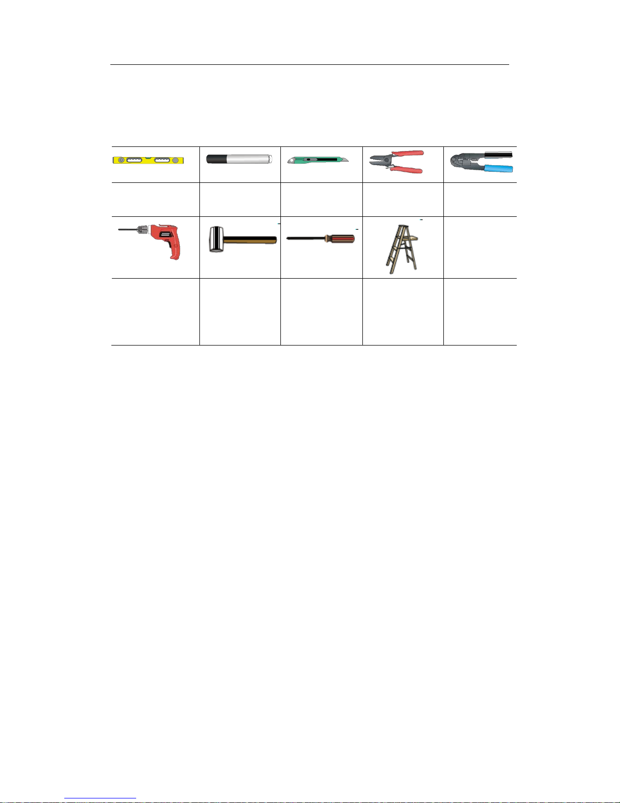
2.4 Installation Tools
When installing DCWL-7962OT outdoor AP, the following tools may be used
(user-owned).
Horizontal
ruler
Permanent
marker
Knife
Wire
stripper
Network pliers
Impact drill (1)
and some
supporting drills
Rubber
hammer
Phillips
screwdriver
Ladder
DCWL-7962OT Outdoor AP
Installation Manual Chapter 3 AP Installation
3-1
Chapter 3 AP Installation
Because the installation position of DCWL-7900 series indoor AP is high normally, the
maintenance personal cannot maintain and debug through the c onsole port to login the
device after installation. We suggest user conducting the basic configuration accordi ng to
need before installing the AP to the appointed position.
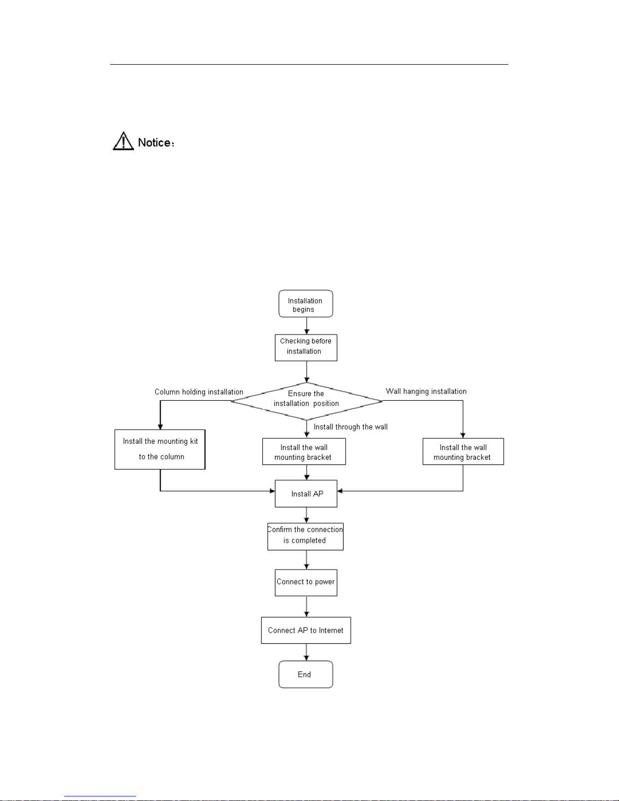
3.1 Installation Process
Fig 3-1 AP installation flow diagram

DCWL-7962OT Outdoor AP
Installation Manual Chapter 3 AP Installation
3-2
3.2 Checking before Installa ti o n
Please check the following items before the AP installation:
Please power to the AP first and connect the AP to the Ethernet, then check the
LED status to make sure the AP can work normally.
Please ensure to complete the wiring in the position of AP installation.
DCWL-7962OT (R5) outdoor AP supports 802.3at standard PoE (Power over
Ethernet) power.
Please record AP’s MAC address and serial number (MAC address and serial
number are on the back of the AP) first for convenient to find and use.
3.3 Ensure the Installation Position
The rules of installation position are as below:
Cut back the obstacles (such as walls) between AP and the user terminal device
as much as possible.
Make the AP’s position far away from the electrical device that can bring the RF
noise (such as the microwave).
The installation position should be hidden as much as possible to prevent
disturbing the inhabitants.
3.4 Install DCWL-7962OT(R5)
The following two installation methods are supported for DCWL-7962OT (R5) outdoor
AP:
Column holding installation
Wall hanging installation
3.4.1 Column Holding Installation
When install the DCWL-7962OT (R5) outdoor AP on the column, the steps are as
below:
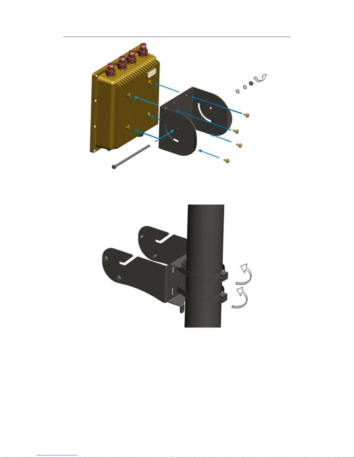
1. Install the backplane at the bottom of DCWL-7962OT (R5), and screw the 4pcs
short screws with the phillips screwdriver. Make the long screw stick passing through the
holes of the backplane and put the flat pad, spring shim and the screw nut on it in proper
order; do not lock it tight.
DCWL-7962OT Outdoor AP
Installation Manual Chapter 3 AP Installation
3-3
Fig 3-2 Install the backplane of DCWL-7962OT (R5) AP
2. Lock the 2PCS stainless tight hoop strip on the stick by passing through the
mounting bracket and lock the fastening screws.
Fig 3-3 Column holding installation of DCWL-7962OT(R5) AP
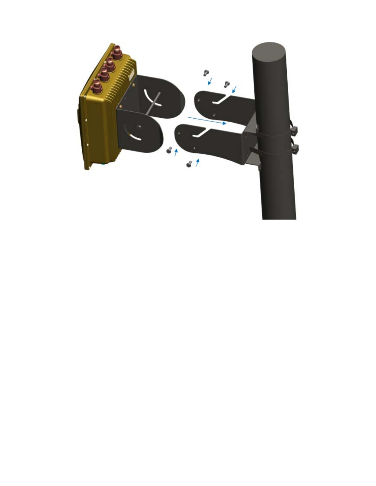
3. Install the device with the back plane to the mounting kit on the column and fix the
device and mounting kit together by using 2pcs short screws and 1pcs long screws.
DCWL-7962OT Outdoor AP
Installation Manual Chapter 3 AP Installation
3-4
Fig 3-4 fixed installation of DCWL-7962OT(R5) AP
3.4.2 Wall Hanging Installation
When install the DCWL-7962OT (R5) outdoor AP with wall hanging method, the
steps are as below:
1. As shown in the fig 3-1, install the backplane at the bott om of DCWL-7962OT (R5)
first;
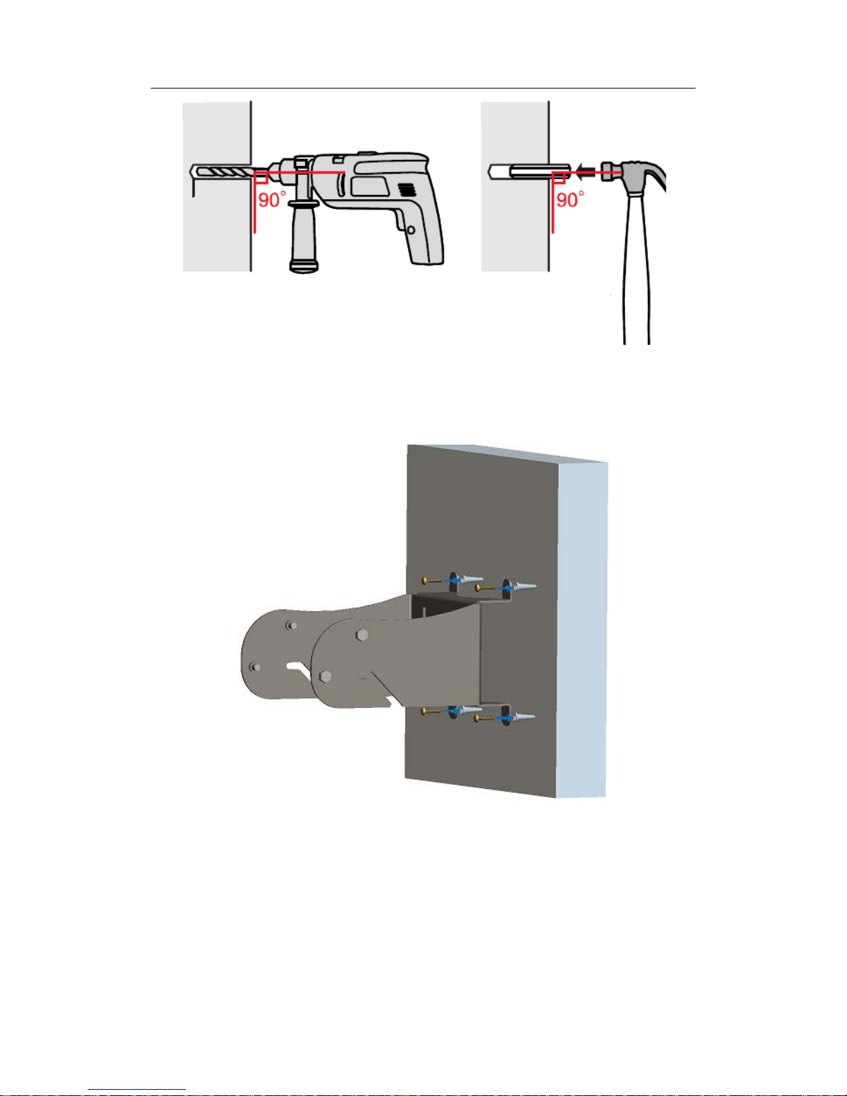
2. Make the AP wall mounting kit flat against the wall and mark the holes that the
crews needs to be installed into, and then punch four holes with the im pact drill; Insert the
expansion bolt into the holes and use the rubber hammer beating it until the expansion
bolt got into the wall completely;
DCWL-7962OT Outdoor AP
Installation Manual Chapter 3 AP Installation
3-5
Fig 3-5 Wall drilling
3. Correspond the screw holes to the expansion bolt holes on the wall, and mak e the
crews pass through the installation holes of the wall mounting kit; Lock the wall m ounting
kit to the wall;
Fig 3-6 Install the wall mounting kit
4. Install the device with the back plane to the mounting kit on the column and fix the
device and mounting kit together by using 4pcs short screws and 1pcs long screws.
 Loading...