

Digital China Networks DCRS-7604E, DCRS-7608E Install Manual

DCRS-7600E InstallManual Content
1
Content
CHAPTER 1 PRODUCT OVERVIEW ......................................... 1-1
1.1 PRODUCT BRIEF ................................................................................. 1-1
1.1.1 Introduction ........................................................................................... 1-1
1.1.2 Main Features ........................................................................................ 1-2
1.2 TECHNICAL SPECIFICATIONS ................................................................. 1-2
1.3 PHYSICAL SPECIFICATIONS .................................................................. 1-6
1.4 HARDWARE COMPONENTS ................................................................... 1-6
1.4.1 Chassis .................................................................................................. 1-6
1.4.2 Introduction to DCRS-7600E Series Cards ....................................... 1-14
1.4.3 Interface description ........................................................................... 1-47
1.4.4 Power supply ...................................................................................... 1-48
1.4.5 Power Distribution Box ...................................................................... 1-52
1.4.6 System Backplane .............................................................................. 1-53
1.4.7 Fan Tray ............................................................................................... 1-54
1.4.8 Dust Gauze .......................................................................................... 1-56
1.4.9 Rear Panel ........................................................................................... 1-57
1.4.10 Side Panels ........................................................................................ 1-59
1.5 SYSTEM FEATURES ........................................................................... 1-61
1.5.1 DCRS-7604E System Features .......................................................... 1-61
1.5.2 DCRS-7608E System Features .......................................................... 1-62
CHAPTER 2 HARDWARE INSTALLATION ............................... 2-1
2.1 INSTALLATION NOTICE ......................................................................... 2-1
2.1.1 Basic Requirements ............................................................................. 2-1
2.1.2 Safety Guidelines .................................................................................. 2-4
2.1.3 Safety Warning ...................................................................................... 2-5
2.1.4 Hot Line Work Safety Guidelines ......................................................... 2-5
2.2 PREPARING FOR INSTALLATION ............................................................. 2-6
2.2.1 Checking Switch Hardware Configuration and Accessories ............ 2-6
2.2.2 Required Tools and Fixings ................................................................. 2-6
2.3 HARDWARE INSTALLATION ................................................................... 2-7
2.3.1 Switch Installation ................................................................................ 2-7
2.3.2 Switch grounding ................................................................................ 2-12
2.3.3 Card and module installation ............................................................. 2-13
2.3.4 Connecting to the Console ................................................................ 2-21
2.3.5 Connecting to the Management Port ................................................ 2-21
2.3.6 SFP transceiver installation ............................................................... 2-22
2.3.7 Copper Cable/Fiber Cable Connection ............................................. 2-22
2.3.8 Power supply connection .................................................................. 2-23
DCRS-7600E InstallManual Chapter 1 Product Overview
1-1
Chapter 1 Product Overview
RECOMMENDATION: Please read this manual f irst before using the switch,
following the instructions to avoid damaging the device.
1.1 Product Brief
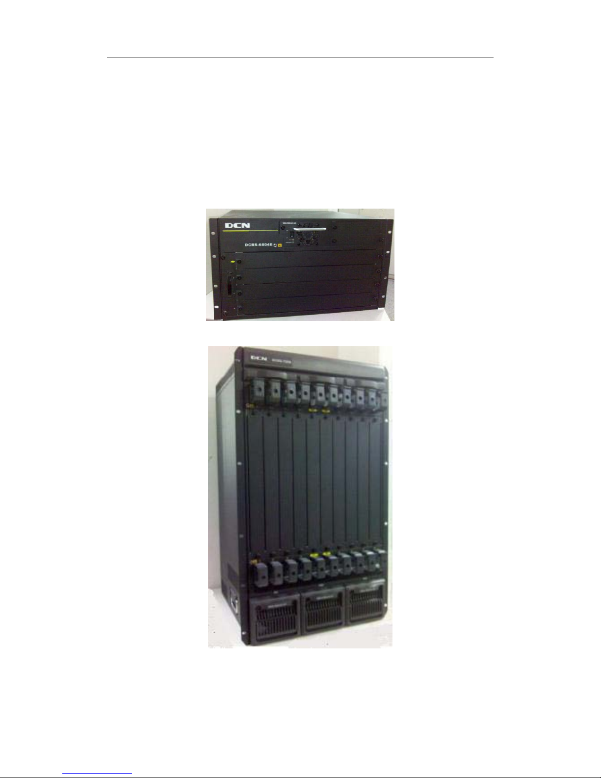
FIG
1-1 DCRS-7604E Switch
FIG 1-2 DCRS-7608E Switch
1.1.1 Introduction

DCRS-7600E InstallManual Chapter 1 Product Overview
1-2
Digital China DCRS-7600E series is a high performance routi ng switch that can be
deployed as a core layer device for campus and enterprise networks, or an aggregation
device for IP metropolitan area networks (MAN).
DCRS-7604E provides 4 slots. DCRS-7608E provides 10 slots, 8 of which are
interface module slots.
DCRS-7600E series supports various types of line cards, and can seamlessly
support network interfaces from 100Mb, 1000Mb to 10G B Ethernet. Featuring functions
such as policy-based routing, IPv6, and load balance, it is capable of flexibly meeting the
different requirements of complex customer environments. Furthermore, DCRS-7600E
series allows redundancy for management modules, power supply. It supports both
AC-input and DC-input* power supplies, with hot-swapping support for cards, power
supplies and fans. The working temperature of all cards can be monitored in real-time,
offering carrier-class reliability.
1.1.2 Main Features
DCRS-7604E 4 slots that can be configured in Primary controller-Primary Backup
mode with 2 management modules and 2 network modules, or Single controller mode
with one management module and 3 network modules.
DCRS-7608E 10 slots that c an be configured in Primary controller-Primary Backup
mode with 2 management modules and 8 network modules, or Single controller mode
with one management module and 8 network modules.
The management modules of DCRS-7604E have network interfaces, and then all the
slots are effective network slots.
Store-and-forward switching, ensuring minimal latency.
Auto MDI/MDI-X, enabled on all RJ-45 ports, allows connections to other switches
using a non-crossover twisted pair cable.
Full-duplex IEEE802.3x flow control, half-duplex backpressure flow control.
Console management port provided.
Port working status and statistics available.
Restart and reset to factory setting can be done both locally and remot ely.
TFTP /FTP firmware upgrade available.
Can be installed into standard 19-inch chassis.
1.2 Technical specifications
Item
DCRS-7604E
DCRS-7608E
Slot
4
10

DCRS-7600E InstallManual Chapter 1 Product Overview
1-3
Port
10/100/1000BASE-T, 192 at best
1000Base-SX, 192 at best
1000Base-LX, 192 at best
10/100BASE-T, 192 at best
10GBase, at best
10/100/1000BASE-T, 384 at best
1000Base-SX, 384 at best
1000Base-LX, 384 at best
10/100BASE-T, 384 at best
10GBase, at best
Backboard
bandwidth
1.2Tbps(can extend to 2.4Tbps) 2.4Tbps(can extend to 4.8Tbps)
Exchange
capacity
640Gbps
1.28Tbps/2.4Tbps (the secon
d
generation engine)
Packet
Forwarding
Speed
476Mpps
952Mpps/1785Mpps
(the second
generation engine)
Forwarding Delay
Time among Ports
<=6ms <=6ms
VLAN Item
4K
4K
Layer 2 Protocol
Specifications
IEEE802.3(10Base-T), IEEE802.3u(100Base-TX), IEEE802.3z(1000BASE-X)
,
IEEE802.3ab(1000Base-T), IEEE802.3ae(10GBase), IEEE802.1Q(VLAN)
,
IEEE802.3ak(10GBASE-CX4), IEEEE802.1d(STP), IEEEE802.1W(RSTP),
IEEEE802.1S(MSTP), IEEE802.1p(COS), IEEE802.1x(Port Control)
,
IEEE802.3x(Flow control), IEEE802.3ad(LACP), Port Mirror, RSPAN, ULDP
,
LLDP, IGMP Snooping, QinQ, GVRP, VLAN, PVLAN, VOICE VLAN,
Protocol
Vlan, Multicast VLAN, Mac Vlan, Broadcast Storm Control
Layer 3 Protocol
Specifications
(IPv4)
Support ARP, ARP Proxy, ARP Limiting Speed, ARP Repeat-Authentication,
Gratuitous ARP
Support DNS client
Support Static Routing, RIPv1/v2, OSPFv2, BGP4, GRE
Unicast Routing Protocol
etc.
Support Routings for OSPF’s different process import each other
Support LPM Routing, Policy-based Routing(PBR), ECMP
Support VRRP, URPF, Black Hole Routing
Support IGMP v1/2/3, DVMRP, PIM-DM, PIM-SM, PIM-SSM, IGMP Proxy
,
anycast RP, MSDP, Static multicast Routing, boundary multi cast Routing etc.
Strengthen
Extend
Support in-embed firewall, IDS, IPSce VPN, Content-exchange service,
Network
Analysis hardware module etc.
Free-Resource
Support

DCRS-7600E InstallManual Chapter 1 Product Overview
1-4
IPv6
Support ICMPv6, ND, DNSv6
Support IPv6 LPM Routing, IPv6 Policy-based Routing(PBR)
Support IPv6 VRRPv3, IPv6 URPF, IPv6 Black Hole Routing
Support RIPng, OSPFv3, BGP4+ Unicast Routing Protocol etc.
Support 6to4 Tunnels, configured Tunnels, ISATAP etc.
Support MLD Snooping, IPv6 Muticast VLAN
Support MLDv1/v2, PIM-SM/DM for IPv6, IPv6 anycast RP,
IPv6 Static multicast
Routing, IPv6 boundary multicast Routing, IPv6 multicast tunnel etc.
Support IPv6 ACL, IPv6 QOS
Strengthen
ARP/NDP Safety
function
Support ARP/NDP Spoofing Prevention, ARP/NDP Scanning Prevention
MPLS
MPLS, LDP, MPLS VPN, MPLS TE, Access public network technology
QoS
Carry out by hardware completely, have no effect for performance.
Each port has 8 queues. Support SP, WRR, SWRR queue scheduling algorithm.
Support traffic class base on 802.1p, ToS, port, DiffServ
Class traffic by ACL;
configure the COS, TOS, DSCP bases class result. Class
traffic by high-layer content for ACL-X’s 80 bytes
Support SP, WRR,
SWRR etc. Provide different service quality requested for
speech, data and video transmit at the same network.
Support Traffic Shaping
Support priority Mark/Remark
ACL
Carry out by hardware completely, have no effect for forwarding performance.
Support Standard ACL and Extended ACL
Support IP ACL, base on IP-subnet ACL, MAC ACL, IP-MAC ACL,
Support IP or MAC based on source/destination, Layer 3 IP protocol type
,
TCP/UDP layer 4 port number, IP priority (DSCP, ToS, Precedence),
base on
VLAN, Tag/Untag, CoS etc.
Support REDIRECT based on ACL, Traffic statistic based on ACL
ACL-X
Support to transfer security policy automaticall y base on t i me.
ACL’s deepness content can be used for QoS sort standard, the deepness can
extend 80 bytes.
DCSCMv4/v6
Support IPv4/IPv6 Multicast Source Controllable
, Prevent lawless Multicast
Source
Support IPv4/IPv6 multicast user Controllable
Support IPv4/IPv6 policy multicast

DCRS-7600E InstallManual Chapter 1 Product Overview
1-5
Port Function
Support MAC+ port binding, IP+ MAC+ port binding, IP+ port binding
Support MAC filter
Support Port Limit(bandwidth management)
Support Port Loopback Detection
Support Port Mirror(CPU Port Mirror, ingress or egress unilateralism/
bidirectional, one-to-one, many-to-one, stride board, stride equipment),
Support Flow Control: HOL prevent head-packet block, half-
duplex back
pressure, full-duplex IEEE802.3x
Support Port aggregation IEEE802.3ad(LACP), port-to-port GEC/FEC,
each
trunk can up to 8 ports, support load equipoise
DHCPv4/v6
Support IPv4/IPv6 DHCP Client, IPv4/IPv6 DHCP Relay,
IPv4/IPv6 DHCP
Snooping
Inside-install IPv4/IPv6 DHCP Server, DHCP Option82
Security Access
Support IEEE 802.1x, DCSM
AAA
Authentication
Support IPv4/IPv6 RADIUS
Security Function
Configuration
Support IPv4/IPv6 syslog
Support the unite for IPv4/IPv6 HTTP and SSL
Support the user IP security inspection for IPv4/IPv6 SNMP
Support MIB and TRAP
Support IPv4/IPv6 FTP/TFTP
Support IPv4/IPv6 NTP
Support RMOM 1, 2, 3, 9 four group
Support the RADIUS authentication for IPv4/IPv6 telnet user name and password
Support IPv4/IPv6 SSHs
The right configuration for users can adopt radius serve r’s shell management
Support the function for timing-reset bases needs
sFlow Function
Support network flow analysis,Support RFC3176,
can realize the flow monitoring
and statistic based on protocol or address
IPFIX
A standard protocol can measure the flow information of the IETE network
Exception
monitoring and
fault check-up
Monitoring the Task exception, Memory exception, CPU utilance, Stack
exception, Switching-
chip exception, board temperature exception etc. And
giving an alarm
Centralized W
eb
Management
Software
It is adopted the Digital China centralized web management software
‘LinkManager’ for unified management.

DCRS-7600E InstallManual Chapter 1 Product Overview
1-6
1.3 Physical Specifications
Management Port
□ One RJ-45 serial port for each management modul e
AC Power Input
□ Input: 90~264V, 50 ~ 60Hz
□ Built-in Universal Power Supply
DC Power Input
□ Input: -36V~ -72VDC
□ Built-in Universal Power Supply
Power Consumption
□ DCRS-7604E: 400W Max
□ DCRS-7608E: 1200W Max
Operating Temperature
□ 0°C ~ 45°C
Storage Temperature
□ -40°C ~ 70°C
Relative humidity
□ 10% ~ 90% with no condensate
Dimension
□ DCRS-7604E 440mm×266mm×421mm (W x H x D)
□ DCRS-7608E 436mm×797mm×478mm (W x H x D)
Weight
□ DCRS-7604E: 30kg (max. full configuration wei ght)
□ DCRS-7608E: 65kg (max. full configuration weight)
Mean Time Before Failure
□ Min. 80,000 Hours MTBF
1.4 Hardware Components
DCRS-7604E consists of the chassis, power supply system, ventilation system,
system board, etc.
1.4.1 Chassis
1.4.1.1 DCRS-7604E Chassis
DCRS-7600E InstallManual Chapter 1 Product Overview
1-7
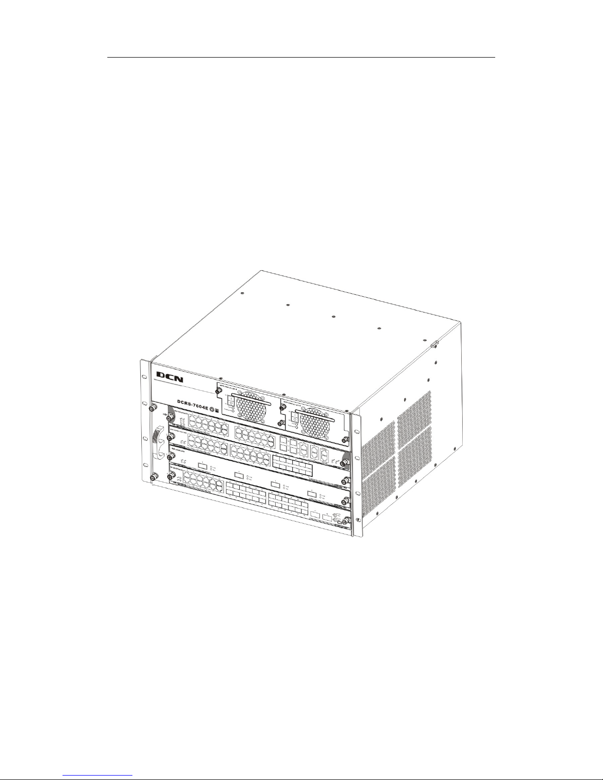
The DCRS-7604E uses a 19-inch Rack Mountable Chassis, with the standard
dimensions of 440mm (W) x 266mm (H) x 421mm (D). The chassi s consists of functional
block and power supply block. The function module bl ock is a board rack, which is the
supporting structure for DCRS-7604E system boards (4 boards max). The fan block is
located on the left side of the board rack, allowing one fan tray (4 axial f ans for each fan
tray). Dust gauze is provided on the right of the board rack for filtering air circulation
through the rack. The power block upper the dust gauze provid es power to the system,
supporting up to two power modules. The po wer modules insert int o the power sl ots from
the front, with the distribution box at the back of the rack for maintenance.
In addition, there is an ESD Wrist Strap Connectors on the board rack, located on the
left side of the upper.
Fig 1-3 DCRS-7604E Module Outlook
DCRS-7600E InstallManual Chapter 1 Product Overview
1-8
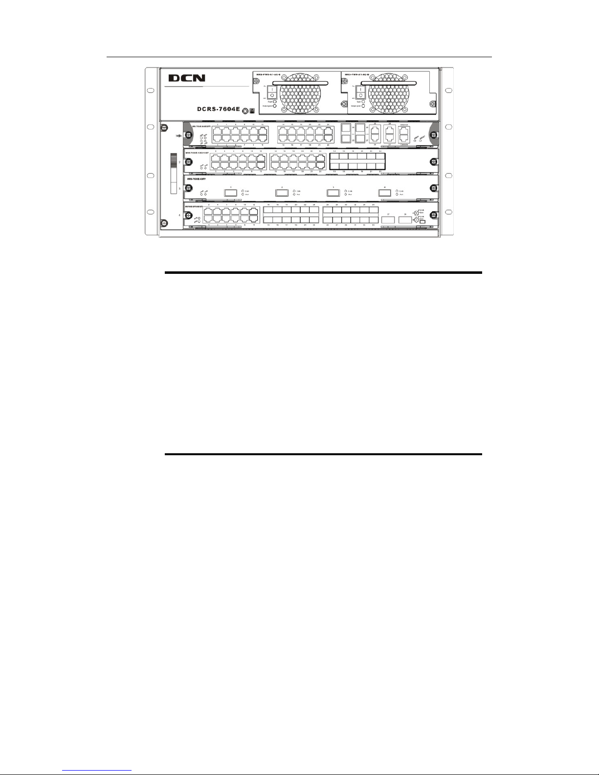
Fig 1-4 DCRS-7604E Front Panel View
① Management slot: It supports two management slots.
MRS-7604E-M1XFP12GX12GB or MRS-7604E-M44GT etc.can be
inserted in to the Management slots.The second slot can als o be used
as I/O slot for configuring various I/O modules.
② Network slot: 2 network slots are provided. Various network modules
can be added to the network slots. Such as MRS-7600E-4XFP and
MRS-7600E-12GX12GT etc.
③ Power slot: Used for system power supply modules. Support up to two
400W AC/DC modules.
④ Fan tray slot: Supports up to one system fan assemblies, each
assembly consists of four axial fans.
⑤ Dust gauze slot: Exterior air inlet for the ventilation subsystem.
⑥ Distribution box slot: For system distribution box use, works in AC
mode based on the power modules.
1.4.1.1.1 Board Rack
The board rack consists of board slots and a system board.
The boards are inserted vertically into t he DCRS-7604E 4 unit boards are provided.
There are four slots in DCRS-7604E from number 1 to number 4 in order of top to down.
The first slot is used to install management module; the second slot is used to
management module under 1+1 redundant backup mode or i nstall various I/O interface
modules.
A reset button (printed on the panel as Reset), hot swap button (printed on the panel
as SWAP), board power indicator (printed on the panel as PWR) and board running status
indicator (printed on the panel as RUN) are provided for each board. On t he Main Control
cards there is Master-Slave indicator (printed on the panel as M/S) T here is also a power
module status indicator (printed on the panel as Power), fan assembly status indicator
(printed on the panel as Fan), and interface status indicators for corresponding

DCRS-7600E InstallManual Chapter 1 Product Overview
1-9
management interfaces and network interfaces (print ed on the panel as Link and Act).
The DCRS-7604E system board is an essential part of the switch, located inside t he
switch and providing interconnectivity between the management switch modules (short for
management card) and network interface modules (line card), and for all management
and control signals.
1.4.1.1.2 Power Supply
When using A.C. power supply, we shall adopt power supply of 110V/220V and
corresponding A.C. distribution box. The permissible range of power supply is 90~
264VAC, 50~60Hz. The maximum output power of single power supply module is 400W.
When using D.C. power supply, we shall adopt power supply of -48V and
corresponding D.C. distribution box. The permissible range of power supply is -36V~
-72VDC. The maximum output power of single power supply module is 400W.
1.4.1.1.3 Ventilation and Cooling System
The operating ambient temperature of the DCRS-7604E is 0 ~ 45°C, the thermal
design of the equipment can ensure that the surface tem perature of the device will not
exceed 50-80% of the highest temperature allowable.
The switch uses fan assemblies to disperse heat, with the air flow being drawn in
through the right section and out through the left section to facilitate air circulation, s o that
the switch can maintain normal operation under specified environmental conditions . The
fan tray is attached to the fan tray slots left the board rack, and ventilation is provided via 4
axial fans that pump out air. Fan trays are hot swappable for maintenance, their status are
indicated by the FAN indicators on the main switch panel. In addition, dust gauze is
provided on the right of the board rack for filtering the air circulating through the rack. The
dust gauze can be unplugged and removed through the back for maintenance.
1.4.1.2 DCRS-7608E Chassis
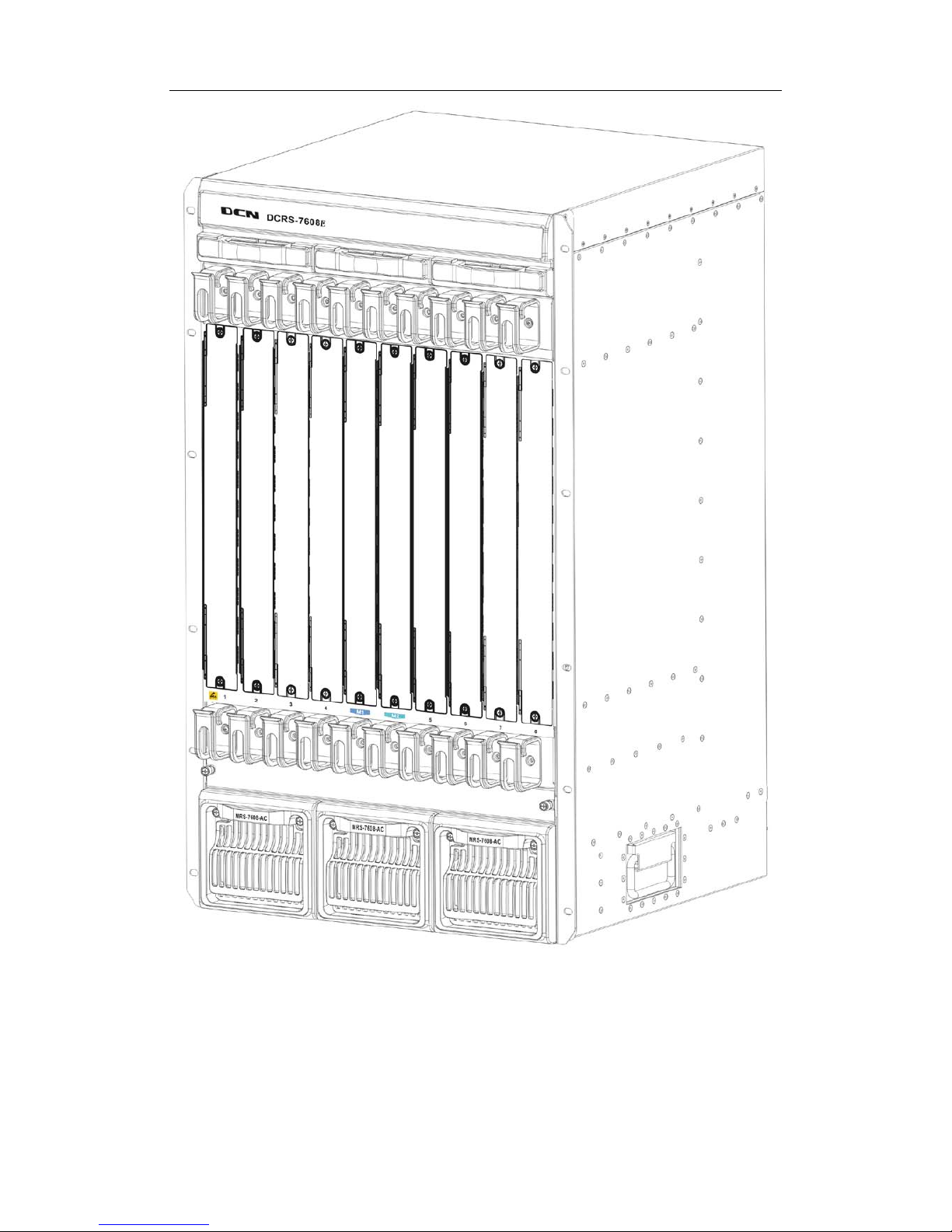
The DCRS-7608E uses a 19-inch Rack Mountable Chassis, with the standard
dimensions of
436mm (W) x 797mm (H) x 478mm (D). The chassis consists of functional
block, thermal block, and power supply block.
The function module block is a board rack, which is the supporting structure for
DCRS-7608E system boards (10 boards max). Ten wiring clips are provided in the upper
and lower parts of the board rack respectively, for the positioning of all kinds of cables. In
addition, there are two ESD Wrist Strap Connectors on t he board rack, located on the left
side of the upper and lower rack respectively.
The thermal block is located on the upper part of the board ra ck, allowing three fan

DCRS-7600E InstallManual Chapter 1 Product Overview
1-10
trays (2 axial fans for each fan tray). Dust gauze is provided under the board rack for
filtering air circulation through the rack.
The power block under the dust gauze provides power to the system, supporting up
to three power modules. The power modules insert into the power slots from the front, with
the distribution box at the back of the rack for maintenance. Closely beside the distribution
box, a grounding post has been provided on each side of the rack for grounding
connections.
In addition, on both sides of the lower section of the chassis, a handler is provided for
easier transport.
DCRS-7600E InstallManual Chapter 1 Product Overview
1-11
Fig
1-5 DCRS-7608E Module Outlook

DCRS-7600E InstallManual Chapter 1 Product Overview
1-12
Fig 1-6 DCRS-7608E Front Panel view

DCRS-7600E InstallManual Chapter 1 Product Overview
1-13
① Management slot: 2 management slots are provided. One or two
management switching modules MRS-7608E-MI can be inserted in to
the Management slots.
② Network slot: 8 network slots are provided. Various network modules
can be added to the network slots, such as MRS-7600E-48GB,
MRS-7600E-4XFP, etc.
③ Power slot: Used for system power supply modules. Supports up to
three 600W AC modules or three 600W DC modules.
④ Fan tray slot: Supports up to three system fan assemblies, each
assembly consists of two axial fans.
⑤ Dust gauze slot: exterior air inlet for the ventilation subsystem.
⑥ Distribution box slot: For system distribution box use, works in AC/DC
mode based on the power modules.
1.4.1.2.1 Board Rack
The board rack consists of board slots and a system board.
The boards are inserted vertically into the DCRS-7608E 10 unit boards are provided.
These include 2 management slots in the middle for management switch modules,
marked specially in red as M1 and M2. The other eight board slots are network slots for
various network interface modules, sequenced as 1 to 8 from left to right.
A reset button (printed on the panel as Reset), hot swap button (printed on the panel
as SWAP), board power indicator (printed on the panel as PWR) and board running status
indicator (printed on the panel as RUN) are provided for each board. On the Main Control
cards there is Master-Slave indicator (printed on the panel as M/S) There is also a power
module status indicator (printed on the panel as Power: Fail/OK), fan assembly status
indicator (printed on the panel as Fan: Alarm/OK), and interface status indicators for
corresponding management interfaces and network interfaces (printed on the panel as
Link and Act).
The DCRS-7608E system board is an essential part of the switch, located inside the
switch and providing interconnectivity between the management switch modules (short for
management card) and network interface modules (line card), and for all management
and control signals.
1.4.1.2.2 Power Supply
When powered by AC sources, the 110V/220 VAC input power supplies and
corresponding AC distribution box should be use d. The acceptable input power ranges
from 90 ~ 264 VAC at 50 ~ 60 Hz. The maximum output power of each power module is
600W.

DCRS-7600E InstallManual Chapter 1 Product Overview
1-14
When powered by DC sources, the -48 VDC input power suppl y and corresponding
DC distribution box should be used. The acceptable input power ranges from -36 V ~ 72
VDC. The maximum output power of each power module is 600W.
1.4.1.2.3 Ventilation and Cooling System
The operating ambient temperature of the DCRS-7608E is 0 ~ 45°C, the thermal
design of the equipment can ensure that the surface tem perature of the device will not
exceed 50-80% of the highest temperature allowable.
The switch uses fan assemblies to disperse heat, with the air flow being drawn in
through the bottom section and out through the upper section to facilitate air circulation, so
that the switch can maintain normal operation under specified environmental condit ions.
Three fan trays are attached to the fan tray slots above the board rack, and ventilation is
provided via 6 axial fans that pump out air. Fan trays are hot swappable for maintenance,
their status are indicated by the FAN indicators on the main switch panel. In addition, dust
gauze is provided under the board rack for filtering the air circulating through the rack. The
dust gauze can be unplugged and removed through the front for maintenance.
1.4.2 Introduction to DCRS-7600E Series Cards
The following eleven cards for the DCRS-7600E series are currently available:
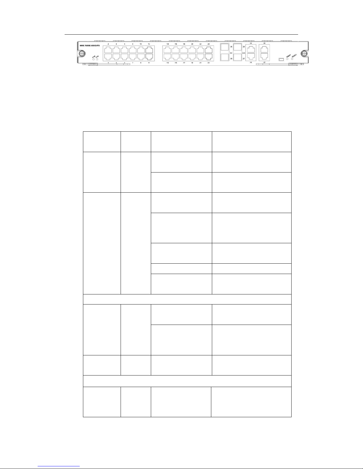
Main control card (MRS-7604E-M4GX24TX): The central switching and
controlling module for the DCRS-7604E, System status control, switch
management, user access control and administration, and network operation
maintenance are performed here. 24 10/10Base-TX ports with 4 Gigabit combo
ports (RJ45 or SFP) are also provided.
Main control card (MRS-7608E-MI): The central switching and controlling
module for the DCRS-7608E. System status control, switch management, user
access control and administration, and network operation maintenance are
performed here.
4 Gigabit Combo ports and 24 100/10 Base-TX ports line card
(MRS-7600E-4GX24TX): supporting 4 Gigabit Combo ports and 24 100/10
Base-TX ports for layer 2 and layer 3 switching and routing.
12 Gigabit Combo ports and 12 copper GT ports (MRS-7600E-12GX12GT):
supporting 12 Gigabit Combo ports and 12 copper GT ports for layer 2 and layer
3 switching and routing and ipv6 wire speed forward.
Dual 10G XFP ports, 12 Gigabit Combo ports and 12 copper Gb ports
(MRS-7600E-2XFP12GX12GT): supporting dual 10G XFP ports, 12 Gigabit

DCRS-7600E InstallManual Chapter 1 Product Overview
1-15
Combo ports and 12 copper GT ports f or layer 2 and layer 3 switching , routing
and IPv6 wire speed forward.
48 copper GT ports line card (MRS-7600E-48GT): supporting 48 1000Base-T
copper ports for layer 2 and layer 3 switchi ng and routing and IPv6 wire speed
forward.
Main control card (MRS-7604E-M1XFP12GX12GT): The central switching and
controlling module for the DCRS-7604E, System status control, switch
management, user access control and administration, and network operation
maintenance are performed here. The board can be insert ed into f irst or second
slots of the chassis for Master-Slave redundancy, and supports IPv6 wire speed
transmission function. 12-port 1G optical-electronic combo, 12-port 1G
electronic and 1-port 10G XFP interface.
40G XFP interface line card (MRS-7600E-4XFP): implements 2-layer and
3-layer wire-speed switching and routing function of 4 10,000Mbps XFP
interfaces and IPv6 wire-speed transmiss i on.
48 copper GT ports line card (MRS-7600E-48GB): implements 2-layer and
3-layer wire-speed switching and routing function of 48 1000Mbps optical
interfaces and IPv6 wire-speed transmission.
Main control card (MRS-7604E-M44GT): The switching module of the
DCRS-7604E switch. System status control, switch manage ment, user access
control and management, and network maintenances are performed here. The
board can be inserted into first or second s lots of the chassis for Master-Slave
redundancy, supports IPv6 wire-speed transmission. It has 44 1000Mbps
electronic interfaces at the same time.
Main control card (MRS-7604E-M1XFP12GX12GB): is switching module for the
DCRS-7604E. System status control, switch management, user ac cess control
and management, and network maintenances are perform ed here. The board
can be inserted into first or second slots of the chassis for Master-Slave
redundancy. It supports 2-layer and 3-layer wire-speed switching and routing
function of 12 1000Mbps optical-electronic combos, 12 1000Mbps opticals and 1
10,000Mbps XFP interfaces, IPv6 wire-speed transmission.
12 1000Mbps optical-electronic combo, 12 1000Mbps optical interfaces line
card(MRS-7600E-12GX12GB): The switching module of the 76 series switch
and implements 2-layer and 3-layer wire-speed switching and routing function of
12 1000Mbps optical-electronic combo, 12 1000Mbps optical interfaces, IPv6
wire-speed transmission.
12 1000Mbps optical-electronic combo, 12 1000Mbps optical and 2 10,000Mbps
XFP interfaces line card (MRS-7600E-2XFP12GX12GB): The switching module

DCRS-7600E InstallManual Chapter 1 Product Overview
1-16
of the 76 series switch and implements 2-layer and 3-layer wire-speed switching
and routing function of 12 1000Mbps optical-electronic combo, 12 1000Mbps
optical and 2 10,000Mbps XFP interfaces, IPv6 wire-speed transmission.
Main control card (MRS-7608E-M2): The second generation central swi tching
and controlling module for the DCRS-7608E. System status control, switch
management, user access control and administration, and network operation
maintenance are performed here.
Main control card (MRS-7608E-M3): The second generation central swi tching
and controlling module for the DCRS-7608E. System status control, switch
management, user access control and administration, and network operation
maintenance are performed here.
12 1000Mbps electronic interfaces, 24 1000Mbps optical interfaces line card
(MRS-7600E-24GB12GT): The switching module for the 7600E series switch,
which supports MPLS VPN function and implements 2-layer and 3-layer
wire-speed switching and routing function of 12 100 0Mbps electronic interfaces,
24 1000Mbps optical interfaces, IPv6 wire-speed transmission.
12 1000Mbps electronic interfaces, 12 1000Mbps optical and 2 10,000Mbps
XFP interfaces line card (MRS-7600E-2XFP24GB12GT): The switching module
for the 7600E series switch , which supports MPLS VPN function and
implements 2-layer and 3-layer wire-speed switching and routi ng function of 12
1000Mbps electronic interfaces, 12 1000Mbps optical and 2 10,000Mbps XFP
interfaces, IPv6 wire-speed transmission.
Dual 10G XFP ports , 12 Gigabit Combo ports and 12 copper Gb ports
(MRS-7600E-2XFP12GX12GT(R2)): The switching module for the
DCRS-7604E(R2), supporting dual 10G XFP ports, 12 Gigabit Combo ports and
12 copper GT ports for layer 2 and layer 3 switching , routing and IPv6 wire
speed forward.
12 Gigabit Combo ports and 12 copper Gb ports (MRS-7600E-12GX12GT(R2)):
The switching module for the DCRS-7604E(R2), supporting 12 Gigabit Com bo
ports and 12 copper GT ports for layer 2 and layer 3 switching , routing and IPv6
wire speed forward.
48 copper GT ports line card (MRS-7600E-48GB (R2)): The switching module
for the DCRS-7604E (R2), implements 2-layer and 3-l ayer wi re -s peed swi tc hing
and routing function of 48 1000Mbps optical interfaces and IPv6 wire-speed
transmission.
Main control card (MRS-7604E-M1XFP12GX12GT (R2)): The central switching
and controlling module for the DCRS-7604E (R2), System status control, switch
management, user access control and administration, and network operation

DCRS-7600E InstallManual Chapter 1 Product Overview
1-17
maintenance are performed here. The board can be insert ed into f irst or second
slots of the chassis for Master-Slave redundancy, and supports IPv6 wire speed
transmission function. 12-port 1G optical-electronic combo, 12-port 1G
electronic and 1-port 10G XFP interface.
Main control card (MRS-7608E-MI (R2)): The central switc hing and controlling
module for the DCRS-7608E (R2). System status control, switch management,
user access control and administration, and networ k operat ion m aintenanc e are
performed here.
1.4.2.1 MRS-7604E-M4GX24TX
The MRS-7604E-M4GX24TX is switching module for the DCRS-7604E. System
status control, switch management, user access control and management, and network
maintenances are performed here. The board can be inserted into firs t or second slots of
the chassis for Master-Slave redundancy. 24 10/10Base-TX ports with 4 Gigabit combo
ports (RJ45or SFP) are also provided.
1.4.2.1.1 Front Panel
The MRS-7604E-M4GX24TX provides 24 10/100Base-TX ports and 4 Gigabit
COMBO slots. At the same time, it comes with 1 Console po rt (control console) and 1
10/100Base-Tx Ethernet port (administration port).
The Front Panel view is shown below:
Fig 1-7 MRS-7604E-M4GX24TX
1.4.2.1.2 Front Panel - Indicator
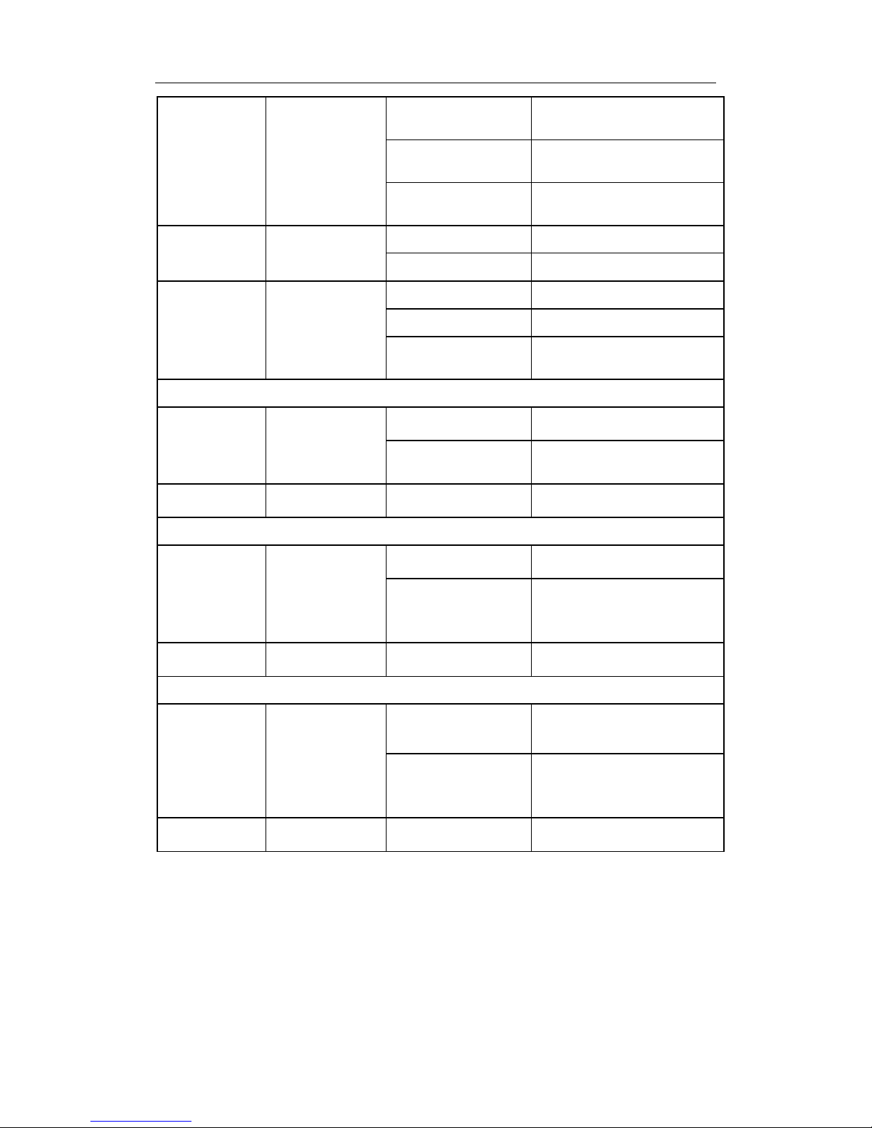
The following table describes the front panel indicators of MRS-7604E-M4GX24TX:
Table 1-1 MRS-7604E-M4GX24TX indicators description
LED Panel Symbol Status Description
Power
Indicator
PWR
On (Green) Card powered
Off Card powered off
Operation
indicator
RUN
On (Green, blink at 1
Hz)
Cards operating normally
On (Green, blink at 8
Hz)
System is loading
DCRS-7600E InstallManual Chapter 1 Product Overview
1-18
On (Yellow, blink at 8
Hz)
System is shutting down
On (Red, blink at 8
Hz)
Cards malfunction
Off
Cards are powered off and
can be removed
Master-Slave
indicator
M/S
On (Green) Master
Off Slave
Fan Assembly
Status
indicator:
FAN
FAN
On (Green) Fan operating normally
On (Red) Fan malfunctioning
Off
Fan not present (with Alarm
off)
SFP port indicator
Status
indicator
Link
On (Green)
Network connection on SFP
transceiver is normal
Off
No network connection
present on SFP transceiver
Transmission
Indicator
Act Blinking (Green) Sending or receiving data
10/100Base-RJ45 port indicator
Status
indicator
Link
On (Green)
Network connection is
normal
Off
No network connection
present on
10/100Base-RJ45 port
Transmission
Indicator
Act Blinking (Green) Sending or receiving data
1000Base-TX port indicator
Status
indicator
Link
On (Green)
Network connection on
1000Base-TX transceiver is
normal
Off
No network connection
present on 1000Base-TX
transceiver
Transmission
Indicator
Act Blinking (Green) Sending or receiving data
1.4.2.1.3 Front Panel Port Description
The E MRS-7604E-M4GX24TX provides 24 10/100Base-TX ports and 4 Gigabite
COMBO (RJ-45 or SFP) transceiver slots.
1.4.2.1.4 Front Panel – Console Port
DCRS-7600E InstallManual Chapter 1 Product Overview
1-19
The MRS-7604E-M4GX24TX provides a RJ-45 (receptacle) Console serial port.
Users can connect to hosts via this port to perform system debugging, configuration,
maintenance, management and host software loading.
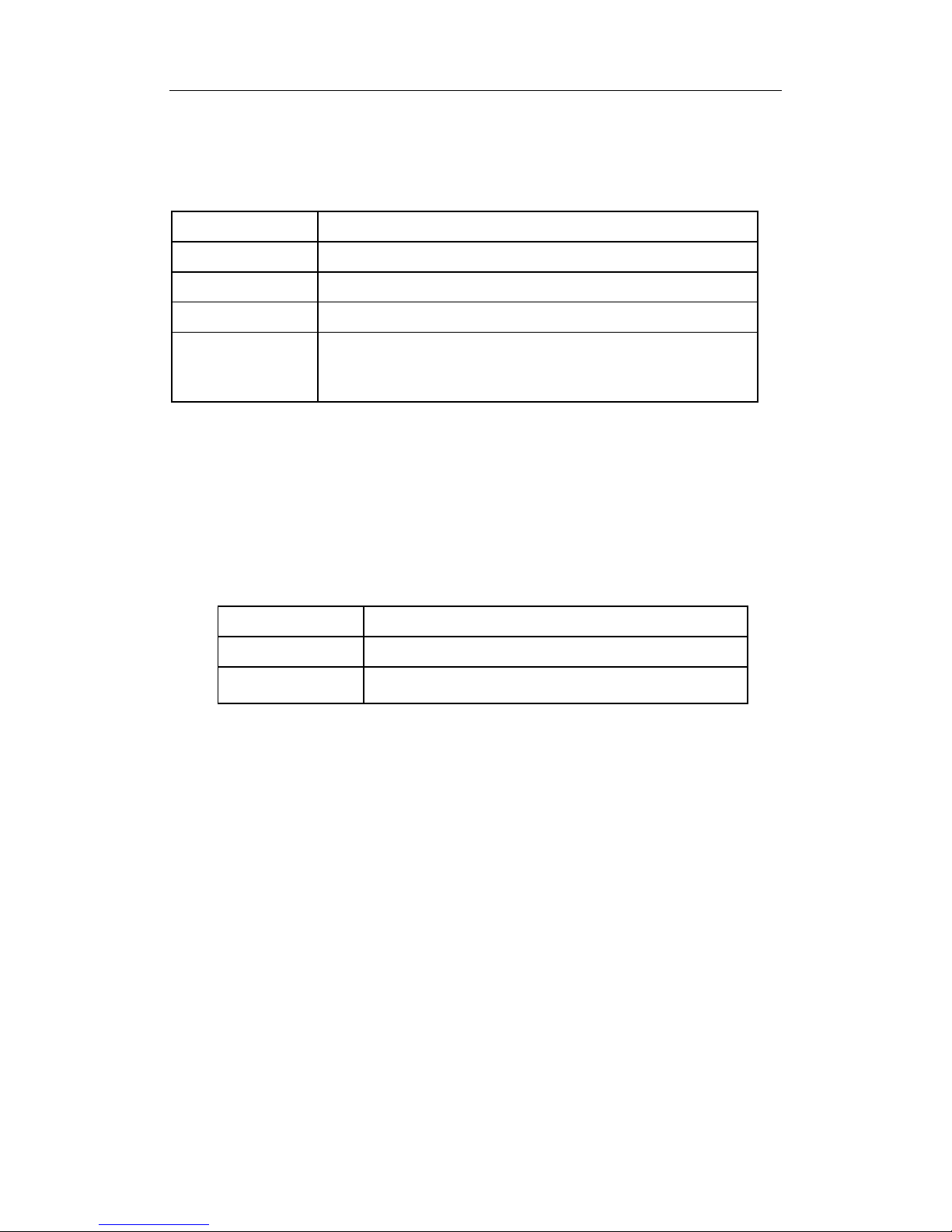
Table 1-2 MRS-7604E-M4GX24TX Console description
Property Specification
Connector
RJ-45 (receptacle)
Connector type
RS-232
Baud rate
9600bps (default)
Supporting service
Connects to character terminals
Connects to PC serial port and run ning terminal emulator
on PC.
1.4.2.1.5 Front Panel – Management Port
The MRS-7604E-M4GX24TX provides a RJ-45 (rec eptacle) Et hernet port. Us ers can
connect through this management port to hosts for program loading or to connect to
remote devices for remote management (e.g., a managing workstation). Note: when
connecting to the host, a cross-over cable should be used.
Table1-3 MRS-7604E-M4GX24TX management port description
Property
Specification
Connector
RJ-45 (Receptacle)
Connector type
10/100Mbps auto sensing
Cat 5 UTP: 100 m
1.4.2.1.6 Front Panel – Reset Button
MRS-7604E-M4GX24TX provides a RESET button for resetting the board.
1.4.2.2 MRS-7608E-MI
The MRS-7608E-MI is switching module for the DCRS-7608E. System status control,
switch management, user access control and management, and network maintenances
are performed here. The board can be inserted into M1 or M2 slots of the chassis for
Master-Slave redundancy.
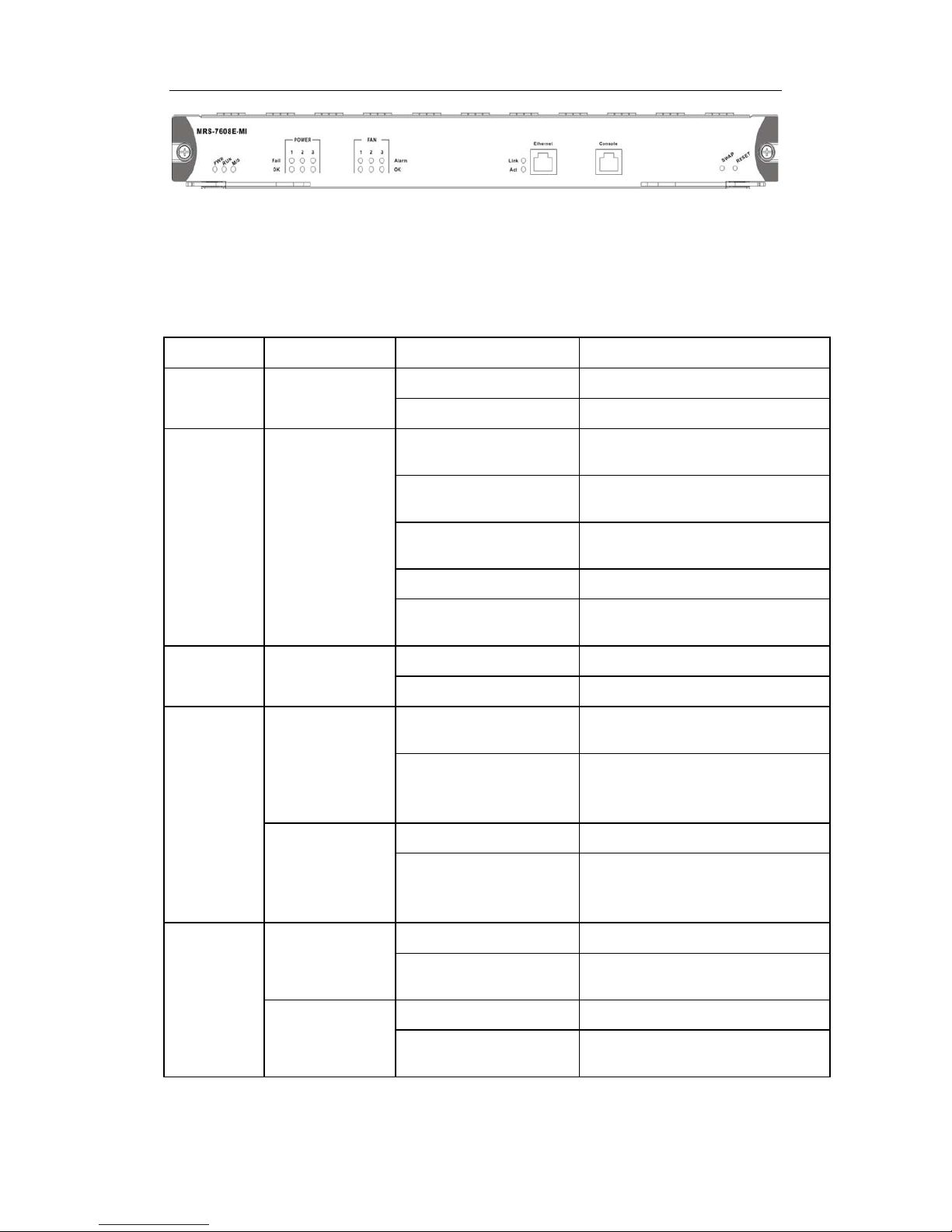
1.4.2.2.1 Front Panel
The MRS-7608E-MI comes with 1 Console port (control console) and 1
10/100Base-Tx Ethernet port (management port).
The Front Panel view is shown below:
DCRS-7600E InstallManual Chapter 1 Product Overview
1-20
Fig 1-8 MRS-7608E-MI Front Panel view
1.4.2.2.2 Front Panel - Indicator
The following table describes the front panel indicators of MRS-7608E-MI:
Table 1-4 MRS-7608E-MI indicators description
LED Panel Symbol Status Description
Power
Indicator
PWR
On (Green) Card powered
Off Card powered off
Operation
indicator
RUN
On (Green, blink at 1
Hz)
Cards operating normally
On (Green, blink at 8
Hz)
System is loading
On (Yellow, blink at 8
Hz)
System is shutting down
On (Red, blink at 8 Hz) Cards malfunction
Off
Cards are powered off and can be
removed
Master-Slav
e indicator
M/S
On (Green) Master
Off Slave
Power
Supply
Module
Status
indicator:
POWER
OK
On (Green)
Power Supply Module operating
normally
Off
Power supply module
malfunctioning or not present (with
Fail off)
Fail
On (Yellow) Power Supply Module malfunction
Off
Power supply module operating
normally or not present (with OK
off)
Fan
Assembly
Status
indicator:
FAN
OK
On (Green) Fan operating normally
Off
Fan malfunctioning or not present
(with Alarm off)
Alarm
On (Yellow) Fan malfunction
Off
Fan operating normally or not
present (with OK off)
1.4.2.2.3 Front Panel – Console Port
DCRS-7600E InstallManual Chapter 1 Product Overview
1-21
The MRS-7608E-MI provides a RJ-45 (receptacle) Console serial port. Users can
connect to hosts via this port to perform system debugging, conf iguration, maintenance,
management and host software loading.
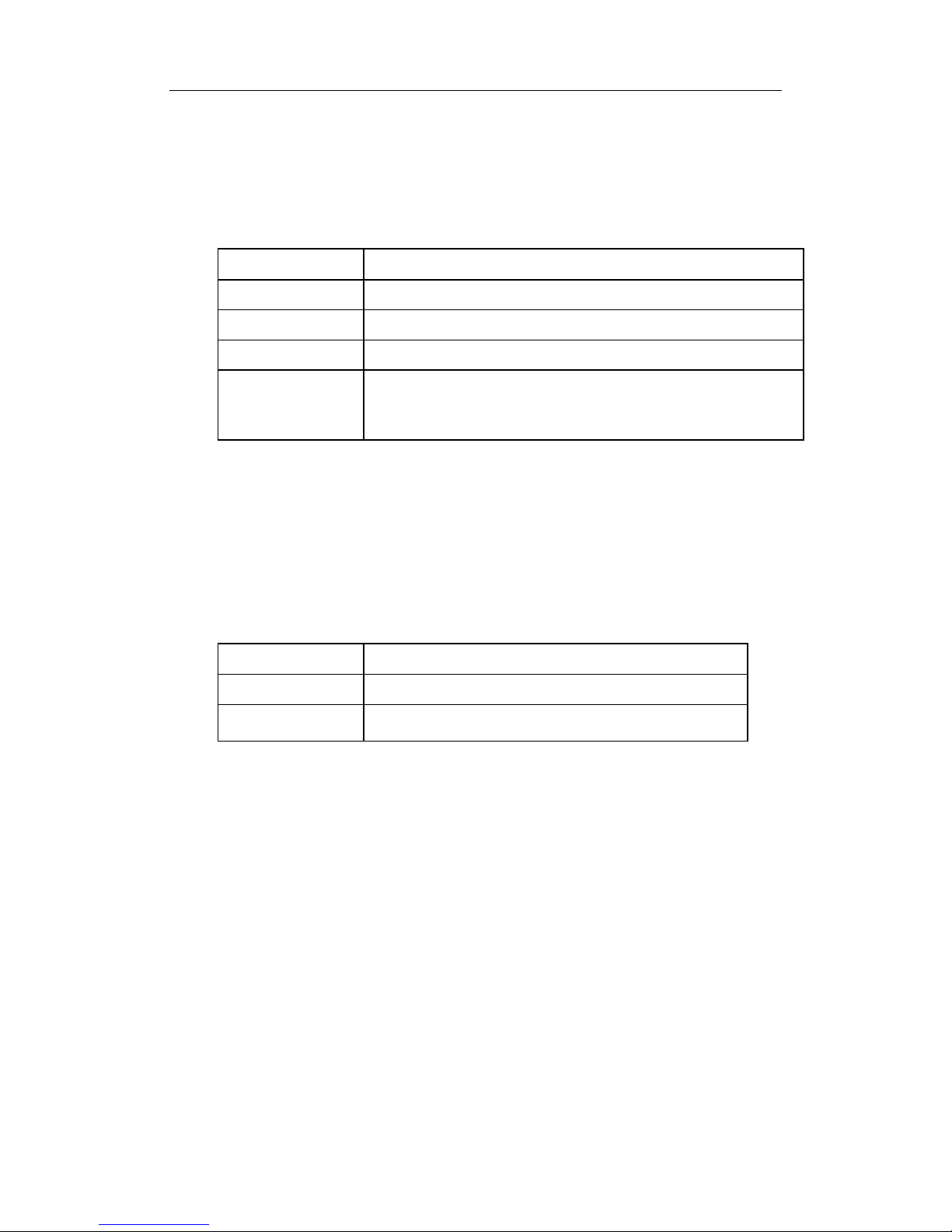
Table 1-5 MRS-7608E-MI Console description
Property Specification
Connector
RJ-45 (receptacle)
Connector type
RS-232
Baud rate
9600bps (default)
Supporting service
Connects to character terminals
Connects to PC serial port and run ning terminal emulator
on PC.
1.4.2.2.4 Front Panel – Management Port
The MRS-7608E-MI provides a RJ-45 (receptacle) Ethernet port. Users can connect
through this management port to hosts for program loading or to connect to remote
devices for remote management (e.g., a managing workstation). Not e: when connecting
to the host, a cross-over cable should be used.
Table 1-6 MRS-7608E-MI management port description
Property Specification
Connector
RJ-45 (Receptacle)
Connector type
10/100Mbps auto sensing
Cat 5 UTP: 300 m
1.4.2.2.5 Front Panel – Reset Button
MRS-7608E-MI provides a RESET button for resetting the board.
1.4.2.3 MRS-7600E-4GX24TX
MRS-7600E-4GX24TX is the line card exchange model of DCRS-7600E series
exchanges. It implements the layer2 and layer3 wire speed exchange and routing function
of twenty four 10/100M electronic ports and four 1G COMBO (4 10/100/1000M electroni c
interfaces or four 1G optical interfaces).
1.4.2.3.1 Front Panel Diagram
MRS-7600E-4GX24TX provides twenty four 10/100M electronic ports and four 1G
COMBO.
DCRS-7600E InstallManual Chapter 1 Product Overview
1-22
Fig
1-9 MRS-7600E-4GX24TX front panel view
1.4.2.3.2 Front Panel Indicator
The description of front panel indicator of MRS-7600E-4GX24TX is as follows:
Table 1-7 MRS-7600E-4GX24TX indicator description
Indicator
Panel
Sign
Status Meanings
Power
Indicator
PWR
On (Green)
Network Interface Card
power on
Off
Network Interface Card
power off
Running
Indicator
RUN
On (Green 1Hz
flash)
Network Interface Card
running in normal status
On (Green 8Hz
flash)
System
loading (Network
Interface Card Booting after
hot plug in)
On (Yellow 8Hz
flash)
System shutting down
On (Red 8Hz flash)
Running status is in failure
Off Network Interface Card is off
and can be pulled out
SFP Interface indicator
Status
Indicator
Link
On (Green)
SFP transceiver network
connection is normal
Off
There is not network
connection at SFP
transceiver
Transmissio
n Indicator
Act Flashes (Green) Sending or receiving data
100MB electronic port indicator
Status
Indicator
Link On (Green)
100MB electronic port
transceiver network
connection is normal

DCRS-7600E InstallManual Chapter 1 Product Overview
1-23
Off
There is not network
connection at 100MB
electronic port transceiver
Transmissio
n Indicator
Act Flashes (Green) Sending or receiving data
1GB Electronic Port Indicator
Status
Indicator
Link
Flashes (Green)
1GB electronic port
transceiver network
connection is normal
Off
There is not network
connection at 1GB
electronic port transceiver
Transmissio
n Indicator
Act Flashes (Green) Sending or receiving data
1.4.2.3.3 Front Panel Interface Description
MRS-7600E-4GX24TX provides twenty four 10/10 0M and four 1G COMBO.
1.4.2.3.4 Front Panel RESET Button
MRS-7600E-4GX24TX provides a RESET button to reset the panel.
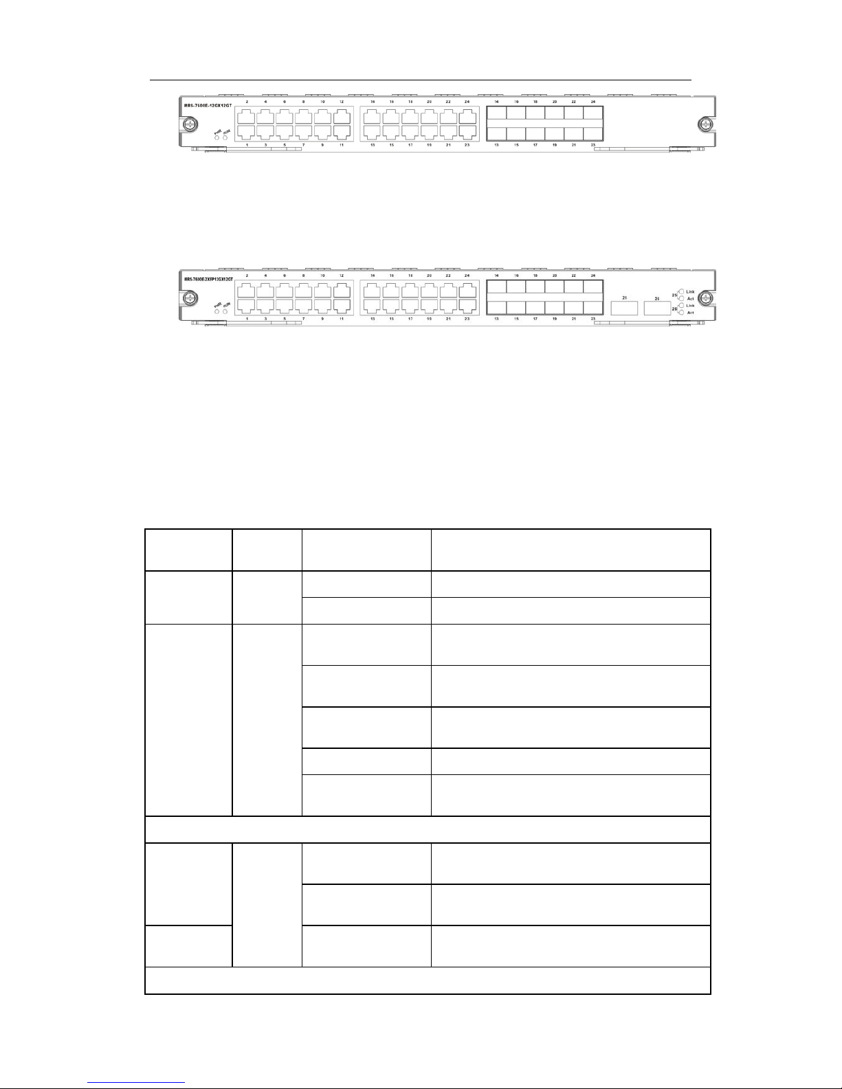
1.4.2.4 MRS-7600E-12GX12GT and
MRS-7600E-2XFP12GX12GT
12-port optical-electronic combo and 12-port electronic interface line card
(MRS-7600E-12GX12GT): to implement the layer 2 and layer3 wire speed exchang e and
routing function of 12-port 1G optical-electronic combo and 12-port 1G electronic interface
and IPv6 wire speed transmission function.
Double 10G and 12-port optical-electronic combo and 12-port electronic interface line
card (MRS-7600E-2XFP12GX12GT): to implement the layer2 and layer3 wire speed
exchange and routing function of 12-port 1G optical-electronic combo, 12-port 1G
electronic and 2-port 10G XFP interface, and IPv6 wire speed transmission function.
1.4.2.4.1 Front Panel Diagram
MRS-7600E-12GX12GT provides twelve 1G SFP ports, twenty four 1G electronic
ports, where the twelve 1G optical ports and the last twelve 1G electronic ports are combo
ports.
DCRS-7600E InstallManual Chapter 1 Product Overview
1-24
Fig 1-10 MRS-7600E-12GX12GT front panel view
MRS-7600E-2XFP12GX12GT provides two 10G XFP ports, twelve 1G optical SFP
ports, twenty four 1G electronic SFP ports, where the twelve 1G optical ports and the last
twelve 1G electronic ports are combo ports.
Fig 1-11 MRS-7600E-2XFP12GX12GT fr ont panel view
1.4.2.4.2 Front Panel Indicator
The description of front panel indicator of MRS-7600E-12GX12GT and
MRS-7600E-2XFP12GX12GT is as follows:
Table 1-8 MRS-7600E-12GX12GT and MRS-7600E-2XFP12GX12GT indicator
description
LED
Indicator
Panel
Sign
Status Meanings
Power
Indicator
PWR
On (Green) Network Interface Card power on
Off Network Interface Card power off
Running
Indicator
RUN
On (Green 1Hz
flash)
Network Interface Card running in normal
status
On (Green 8Hz
flash)
System loading (Network Interface Card
Booting after hot plug in)
On (Yellow 8Hz
flash)
System shutting down
On (Red 8Hz flash) Running status is in failure
Off
Network Interface Card is off and can be
pulled out
RJ-45 Interface indicator
Status
Indicator
Shared
On (Green)
RJ-
45 Interface Network Connection is
normal
Off
There is not network connection at RJ-45
interface
Transmissio
n Indicator
On (Yellow) Sending or receiving data
SFP Interface Indicator
DCRS-7600E InstallManual Chapter 1 Product Overview
1-25
Status
Indicator
“Left
Light”
On (Green)
SFP transceiver network connection is
normal
Off
There is not network connection at SFP
interface
Transmissio
n Indicator
“Right
Light”
Flashes (Green) Sending or receiving data
XFP interface Indicator
Status
Indicator
Link
On (Green)
XFP transceiver network connection is
normal
Off
There is not network connection at XFP
transceiver
Transmissio
n Indicator
Act Flashes (Green) Sending or receiving data
1.4.2.4.3 Front Panel Interface Description
MRS-7600E-12GX12GT and MRS-7600E-2XFP12GX12GT provide twelve SFP 1G
optical fibre transceivers and twenty four RJ-45 1 G electronic port slots.
MRS-7600E-2XFP12GX12GT provides two XFP 10G optical ports.
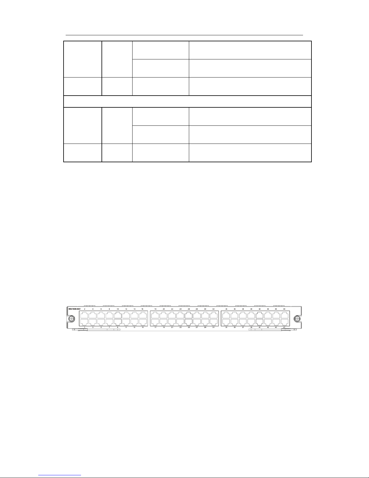
1.4.2.5 MRS-7600E-48GT
48GT electronic interface line card (MRS-7600E-48GT): to implement the layer2 and
layer3 wire speed exchange and routing function of 48GT electroni c interface and IPv6
wire speed transmission function.
1.4.2.5.1 Front Panel Diagram
MRS-7600E-48GT provides 48-Port 10/100/1000M Ethernet electronic ports,
Fig 1-12 MRS-7600E-48GT front panel view
The ports in the above chart are port GE1-GE48 from the bottom-left corner to the
top-right corner. The indicator lamps of ports having odd index number are on the left side
of the port array, while the indicator lamps of ports having even index number are on the
right side. The lamps are green and orange double indicator lamps.
1.4.2.5.2 Front Panel Indicator
The description of front panel indicator of MRS-7600E-48GT as foll ows:
DCRS-7600E InstallManual Chapter 1 Product Overview
1-26
Table 1-9 MRS-7600E-48GT indicator description
LED
Indicator
Panel
Sign
Status Meanings
RJ-45 Interface indicator
Status
Indicator
Shared
On (Green)
RJ-
45 Interface Network Connection is
normal
Off
There is not network connection at RJ-45
interface
Transmissio
n Indicator
On (Yellow) Sending or receiving data
1.4.2.5.3 Front Panel Interface Description
MRS-7600E-48GT provides 48-port 10/100/1000M RJ-45 electronic port.
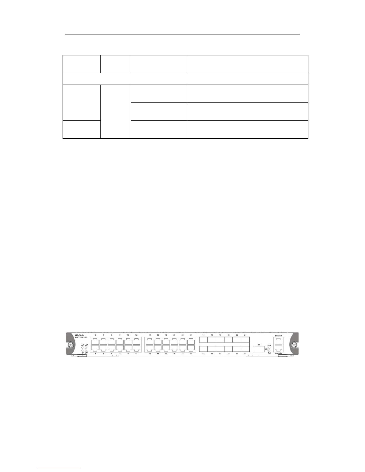
1.4.2.6 MRS-7604E-M1XFP12GX12GT
The MRS-7604E-M1XFP12GX12GT is switching module for the DCRS-7604E.
System status control, switch management, user acc ess control and management, and
network maintenances are performed here. The board can be inserted into first or second
slots of the chassis for Master-Slave redundancy. 12-port 1G optical-electronic combo,
12-port 1G electronic and 2-port 10G XFP interface, and IPv6 wire speed transmission
function.
1.4.2.6.1 Front Panel Diagram
MRS-7604E-MIXFP12GX12GT provides 2-port 1G optical-electronic combo, 12-port
1G electronic and 1-port 10G XFP interface. It implements 2-layer and 3-layer wire-speed
switching, routing function and IPv6 transmission. The front 12 ports are 1000M electronic
ports and the last 12 ports are combo ports.
Fig 1-13 MRS-7604E-M1XFP12GX12GT front panel view
1.4.2.6.2 Front Panel Indicator
The description of front panel indicator of MRS-7604E-M1XFP12GX12GT as follows:
Table 1-10 MRS-7604E-M1XFP12GX12GT indicator description
 Loading...