

Digital China Networks DCRS-7604, DCRS-7608 Installation Manual

DCRS-7600 series
Chassis Core Routing Switch
Installation Manual
(v1.6)
Digital China networks Co.Ltd

1
Preface
DCRS-7600 serial switch is a high performance routing switch released by
Digitalchina network that can be deployed as the core layer device for campus and
enterprise networks, or as an aggregation device for IP metropolitan area networks
(MAN). DCRS-7600 serial switch provides 4 and 10 slots, with support for various types of
line cards and can seamlessly support a variety of network interfaces from 100Mb,
1000Mb to 10GB Ethernet.
We are providing this manual for your better understanding, use and maintenance of
the DCRS-7600. We strongly recommend you to read through this manual carefully
before installation and configuration to avoid possible malfunction or damage to the switch.
Furthermore, we sincerely hope our products and services satisfy you.

2
FCC - Class A
This equipment has been tested and found to comply with the limits for a Class A
digital device, pursuant to part 15 of the FCC Rules. These limits are designed to provide
reasonable protection against harmful interference when the equipment is operated in a
commercial environment. This equipment generates, uses, and can radiate radio
frequency energy and, if not installed and used in accordance with the instruction manual,
may cause harmful interference to radio communications. Operation of this equipment in a
residential area is likely to cause harmful interference in which case the user will be
required to correct the interference at his own expense.
You are cautioned that changes or modifications not expressly approved by the party
responsible for compliance could void your authority to operate the equipment.
You may use unshielded twisted-pair (UTP) for RJ-45 connections - Category 3 or
better for 10 Mbps connections, Category 5 or better for 100 Mbps connections, Category
5, 5e, or 6 for 1000 Mbps connections. For fiber optic connections, you may use 50/125 or
62.5/ 125 micron multimode fiber or 9/125 micron single-mode fiber.

DCRS-7600 InstallManual Content
3
Content
CHAPTER 1 PRODUCT OVERVIEW.........................................1-1
1.1 PRODUCT BRIEF .................................................................................1-1
1.1.1 Introduction...........................................................................................1-1
1.1.2 Main Features........................................................................................1-2
1.2 TECHNICAL SPECIFICATIONS.................................................................1-2
1.3 PHYSICAL SPECIFICATIONS ..................................................................1-3
1.4 HARDWARE COMPONENTS...................................................................1-4
1.4.1 Chassis..................................................................................................1-4
1.4.2 Introduction to DCRS-7600 Series Cards .........................................1-11
1.4.3 Interface description...........................................................................1-46
1.4.4 Power supply ......................................................................................1-48
1.4.5 Power Distribution Box......................................................................1-54
1.4.6 System Backplane..............................................................................1-56
1.4.7 Fan Tray ............................................................................................... 1-57
1.4.8 Dust Gauze..........................................................................................1-59
1.4.9 Rear Panel ...........................................................................................1-60
1.4.10 Side Panels........................................................................................1-62
1.5 SYSTEM FEATURES ...........................................................................1-64
1.5.1 DCRS-7604 System Features.............................................................1-64
1.5.2 DCRS-7608 System Features.............................................................1-65
CHAPTER 2 HARDWARE INSTALLATION ...............................2-1
2.1 BASIC REQUIREMENTS ........................................................................2-1
2.1.1 Site Requirements ................................................................................2-1
2.1.2 Temperature and Humidity Requirements..........................................2-1
2.1.3 Dust and Particles.................................................................................2-2
2.1.4 Preventing Electrostatic Discharge Damage......................................2-3
2.1.5 Anti-interference Requirements...........................................................2-3
2.1.6 Rack Configuration............................................................................... 2-3
2.1.7 Power Supply Requirements...............................................................2-4
2.2 SAFETY GUIDELINES ...........................................................................2-5
2.3 SAFETY WARNING ...............................................................................2-5
2.4 HOT LINE WORK SAFETY GUIDELINES..................................................2-5
2.5 PREPARING FOR INSTALLATION.............................................................2-6
2.5.1 Checking Switch Hardware Configuration and Accessories ............2-6
2.5.2 Required Tools and Utilities.................................................................2-7
2.6 HARDWARE INSTALLATION ...................................................................2-8
2.6.1 Switch Installation ................................................................................2-8
2.6.2 Switch grounding................................................................................2-12

DCRS-7600 InstallManual Content
4
2.6.3 Card and module installation.............................................................2-13
2.6.4 Connecting to the Console ................................................................2-20
2.6.5 Connecting to the Management Port ................................................ 2-20
2.6.6 SFP transceiver installation...............................................................2-21
2.6.7 Copper Cable/Fiber Cable Connection .............................................2-21
2.6.8 Power supply connection ..................................................................2-22
DCRS-7600 InstallManual Chapter 1 Product Overview
1-1
Chapter 1 Product Overview
RECOMMENDATION: Please read this manual first before using the switch,
following the instructions to avoid damaging the device.
1.1 Product Brief
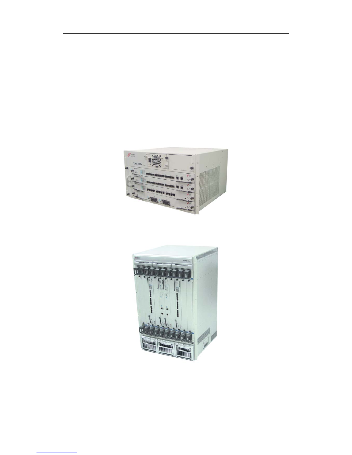
FIG
1-1 DCRS-7604 Switch
FIG 1-2 DCRS-7608 Switch
1.1.1 Introduction

DCRS-7600 InstallManual Chapter 1 Product Overview
1-2
Digital China DCRS-7600 series is a high performance routing switch that can be
deployed as a core layer device for campus and enterprise networks, or an aggregation
device for IP metropolitan area networks (MAN).
DCRS-7604 provides 4 slots, 3 or 2 of which are interface module slots. DCRS-7608
provides 10 slots, 8 of which are interface module slots. DCRS-7600 series supports
various types of line cards, and can seamlessly support network interfaces from 100Mb,
1000Mb to 10GB Ethernet. Featuring functions such as policy-based routing, IPv6, and
load balance, it is capable of flexibly meeting the different requirements of complex
customer environments. Furthermore, DCRS-7600 series allows redundancy for
management modules, power supply. It supports both AC-input and DC-input* power
supplies, with hot-swapping support for cards, power supplies and fans. The working
temperature of all cards can be monitored in real-time, offering carrier-class reliability.
1.1.2 Main Features
DCRS-7604 4 slots that can be configured in Primary controller-Primary Backup mode
with 2 management modules and 2 network modules, or Single controller mode with
one management module and 3 network modules.
DCRS-7608 10 slots that can be configured in Primary controller-Primary Backup
mode with 2 management modules and 8 network modules, or Single controller mode
with one management module and 8 network modules.
Store-and-forward switching, ensuring minimal latency.
Auto MDI/MDI-X, enabled on all RJ-45 ports, allows connections to other switches
using a non-crossover twisted pair cable.
Full-duplex IEEE802.3x flow control, half-duplex backpressure flow control.
Console management port provided.
Port working status and statistics available.
Restart and reset to factory setting can be done both locally and remotely.
TFTP /FTP firmware upgrade available.
Can be installed into standard 19-inch chassis.
1.2 Technical specifications
Protocols and Standards
□ IEEE802.3 10BASE-T Ethernet
□ IEEE802.3u 100BASE-TX/FX Fast Ethernet
□ IEEE802.3x Flow control

DCRS-7600 InstallManual Chapter 1 Product Overview
1-3
□ IEEE802.1x access control
□ IEEE802.1D/w Spanning Tree
□ IEEE802.1p Class of Service
□ IEEE802.1Q VLAN
□ IEEE802.3ad Link Aggregation
□ TFTP/FTP
□ DHCP
□ BootP
□ Telnet
□ IP/UDP/TCP/ICMP
□ HTTP
□ SNMP V1/V2C
□ RIP
□ OSPF
□ BGP
Management Protocols and Methods
□ CLI command line
□ SNMP V1/V2C enabled, available through Network management systems such as
ECview
□ Telnet management enabled
□ RFC1757 RMON(1, 2, 3, 9)
MIB Library
□ RFC1213 MIB II
□ RFC1493 Bridge MIB
□ RFC1643 Ether-Like MIB
□ Digital China Private MIB
1.3 Physical Specifications
Management Port
□ One RJ-45 serial port for each management module
AC Power Input
□ 200 ~ 264VAC, 50 ~ 60Hz
□ Built-in Universal Power Supply
Power Consumption
□ DCRS-7604: 400W Max
□ DCRS-7608: 1200W Max

DCRS-7600 InstallManual Chapter 1 Product Overview
1-4
Operating Temperature
□ 0°C ~ 40°C
Storage Temperature
□ -40°C ~ 70°C
Relative humidity
□ 10% ~ 90% with no condensate
Dimension
□ DCRS-7604 445mm×266mm×421mm (W x H x D)
□ DCRS-7604(V2.0 above) 440mm×266mm×421mm (W x H x D)
□ DCRS-7608 436mm×797mm×478mm (W x H x D)
Weight
□ DCRS-7604: 30kg (max. full configuration weight)
□ DCRS-7608: 65kg (max. full configuration weight)
Mean Time Before Failure
□ Min. 80,000 Hours MTBF
1.4 Hardware Components
DCRS-7604 consists of the chassis, power supply system, ventilation system, system
board, etc.
1.4.1 Chassis
1.4.1.1 DCRS-7604 Chassis
The DCRS-7604 uses a 19-inch Rack Mountable Chassis, with the standard
dimensions of 445mm(W) x 266(H) x 421mm(D),the DCRS-7604(V2.0 above) with the
dimensions of 440mm(W) x 266mm(H) x 421mm(D). The chassis consists of functional
block and power supply block. The function module block is a board rack, which is the
supporting structure for DCRS-7604 system boards (4 boards max). The fan block is
located on the left side of the board rack, allowing one fan tray (4 axial fans for each fan
tray). Dust gauze is provided on the right of the board rack for filtering air circulation
through the rack. The power block upper the dust gauze provides power to the system,
supporting up to two power modules. The power modules insert into the power slots from
the front, with the distribution box at the back of the rack for maintenance. In addition,
there is an ESD Wrist Strap Connectors on the board rack, located on the left side of the
upper.
DCRS-7600 InstallManual Chapter 1 Product Overview
1-5
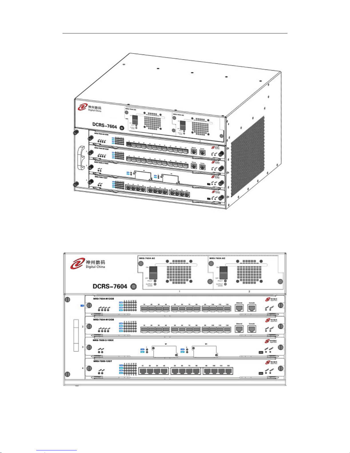
Fig 1-3 DCRS-7604 Module Outlook
Fig 1-4 DCRS-7604 Front Panel View

DCRS-7600 InstallManual Chapter 1 Product Overview
1-6
① Management slot: It supports two management slots.
MRS-7604-M4GX24TX(V2.1) or MRS-7604-M12GB etc.can be
inserted in to the Management slots.The second slot can also be used
as I/O slot for configuring various I/O modules, such as
MRS-7600-12GT , MRS-7600-12GB,MRS-7600-4XFP and more.
② Network slot: 2 network slots are provided. Various network modules
can be added to the network slots.
③ Power slot: Used for system power supply modules. Supports up to
two 400W AC modules.
④ Fan tray slot: Supports up to one system fan assemblies, each
assembly consists of four axial fans.
⑤ Dust gauze slot: Exterior air inlet for the ventilation subsystem.
⑥ Distribution box slot: For system distribution box use, works in AC
mode based on the power modules.
1.4.1.1.1 Board Rack
The board rack consists of board slots and a system board.
The boards are inserted vertically into the DCRS-7604 4 unit boards are provided.
There are four slots in DCRS-7604 from number 1 to number 4 in order of top to down.
The first slot is used to install management module; the second slot is used to
management module under 1+1 redundant backup mode or install various I/O interface
modules.
A reset button (printed on the panel as Reset), hot swap button (printed on the panel
as SWAP), board power indicator (printed on the panel as PWR) and board running status
indicator (printed on the panel as RUN) are provided for each board. On the Main Control
cards there is Master-Slave indicator (printed on the panel as M/S) There is also a power
module status indicator (printed on the panel as Power), fan assembly status indicator
(printed on the panel as Fan), and interface status indicators for corresponding
management interfaces and network interfaces (printed on the panel as Link and Act).
The DCRS-7604 system board is an essential part of the switch, located inside the
switch and providing interconnectivity between the management switch modules (short for
management card) and network interface modules (line card), and for all management
and control signals.
1.4.1.1.2 Power Supply
When using A.C. power supply, we shall adopt power supply of 200~264v and
corresponding A.C. distribution box. The permissible range of power supply is ±20%,
50Hz~60Hz. The maximum output power of single power supply module is 400W.
1.4.1.1.3 Ventilation and Cooling System

DCRS-7600 InstallManual Chapter 1 Product Overview
1-7
The operating ambient temperature of the DCRS-7604 is 0 ~ 45°C, the thermal
design of the equipment can ensure that the surface temperature of the device will not
exceed the 50°C to 80°C, the highest temperature allowable.
The switch uses fan assemblies to disperse heat, with the air flow being drawn in
through the right section and out through the left section to facilitate air circulation, so that
the switch can maintain normal operation under specified environmental conditions. The
fan tray is attached to the fan tray slots left the board rack, and ventilation is provided via 4
axial fans that pump out air. Fan trays are hot swappable for maintenance, their status are
indicated by the FAN indicators on the main switch panel. In addition, dust gauze is
provided on the right of the board rack for filtering the air circulating through the rack. The
dust gauze can be unplugged and removed through the back for maintenance.
1.4.1.2 DCRS-7608 Chassis
The DCRS-7608 uses a 19-inch Rack Mountable Chassis, with the standard
dimensions of
436mm(W) x 797mm(H) x 478mm(D). The chassis consists of functional
block, thermal block, and power supply block. The function module block is a board rack,
which is the supporting structure for DCRS-7608 system boards (10 boards max). Ten
wiring clips are provided in the upper and lower parts of the board rack respectively, for
the positioning of all kinds of cables. In addition, there are two ESD Wrist Strap
Connectors on the board rack, located on the left side of the upper and lower rack
respectively. The thermal block is located on the upper part of the board rack, allowing
three fan trays (2 axial fans for each fan tray). Dust gauze is provided under the board
rack for filtering air circulation through the rack. The power block under the dust gauze
provides power to the system, supporting up to three power modules. The power modules
insert into the power slots from the front, with the distribution box at the back of the rack
for maintenance. Closely beside the distribution box, a grounding post has been provided
on each side of the rack for grounding connections. In addition, on both sides of the lower
section of the chassis, a handler is provided for easier transport.

DCRS-7600 InstallManual Chapter 1 Product Overview
1-8
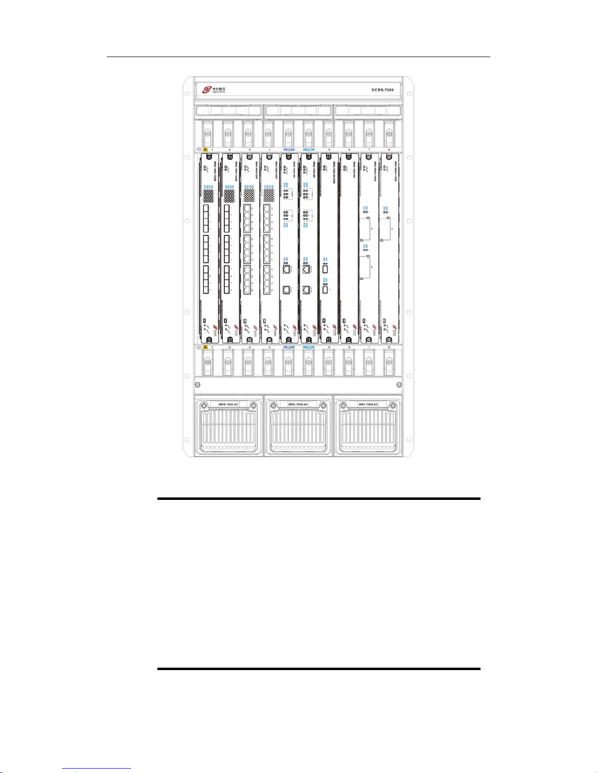
Fig
1-5 DCRS-7608 Module Outlook
DCRS-7600 InstallManual Chapter 1 Product Overview
1-9
Fig
1-6 DCRS-7608 Front Panel view
① Management slot: 2 management slots are provided. One or two
management switching modules MRS-7608-MI can be inserted in to the
Management slots.
② Network slot: 8 network slots are provided. Various network modules
can be added to the network slots, such as MRS-7600-12GT,
MRS-7600-12GB, MRS-7600-4XFP, etc.
③ Power slot: used for system power supply modules. Supports up to
three 600W AC modules or three 600W DC modules.
④ Fan tray slot: Supports up to three system fan assemblies, each
assembly consists of two axial fans.
⑤ Dust gauze slot: exterior air inlet for the ventilation subsystem.
⑥ Distribution box slot: For system distribution box use, works in AC/DC
mode based on the power modules.

DCRS-7600 InstallManual Chapter 1 Product Overview
1-10
1.4.1.2.1 Board Rack
The board rack consists of board slots and a system board.
The boards are inserted vertically into the DCRS-7608 10 unit boards are provided.
These include 2 management slots in the middle for management switch modules,
marked specially in red as M1 and M2. The other eight board slots are network slots for
various network interface modules, sequenced as 1 to 8 from left to right.
A reset button (printed on the panel as Reset), hot swap button (printed on the panel
as SWAP), board power indicator (printed on the panel as PWR) and board running status
indicator (printed on the panel as RUN) are provided for each board. On the Main Control
cards there is Master-Slave indicator (printed on the panel as M/S) There is also a power
module status indicator (printed on the panel as Power: Fail/OK), fan assembly status
indicator (printed on the panel as Fan: Alarm/OK), and interface status indicators for
corresponding management interfaces and network interfaces (printed on the panel as
Link and Act).
The DCRS-7608 system board is an essential part of the switch, located inside the switch
and providing interconnectivity between the management switch modules (short for
management card) and network interface modules (line card), and for all management
and control signals.
1.4.1.2.2 Power Supply
When powered by AC sources, the 110V/220 VAC input power supplies and
corresponding AC distribution box should be used. The acceptable input power ranges
from 90 ~ 264 VAC at 50 ~ 60 Hz. The maximum output power of each power module is
600W.
When powered by DC sources, the -48 VDC input power supply and corresponding
DC distribution box should be used. The acceptable input power ranges from -36 V ~ 72
VDC. The maximum output power of each power module is 600W.
1.4.1.2.3 Ventilation and Cooling System
The operating ambient temperature of the DCRS-7608 is 0 ~ 40°C, the thermal
design of the equipment can ensure that the surface temperature of the device will not
exceed the 50°C to 80°C, the highest temperature allowable.
The switch uses fan assemblies to disperse heat, with the air flow being drawn in
through the bottom section and out through the upper section to facilitate air circulation, so
that the switch can maintain normal operation under specified environmental conditions.
Three fan trays are attached to the fan tray slots above the board rack, and ventilation is
provided via 6 axial fans that pump out air. Fan trays are hot swappable for maintenance,

DCRS-7600 InstallManual Chapter 1 Product Overview
1-11
their status are indicated by the FAN indicators on the main switch panel. In addition, dust
gauze is provided under the board rack for filtering the air circulating through the rack. The
dust gauze can be unplugged and removed through the front for maintenance.
1.4.2 Introduction to DCRS-7600 Series Cards
The following eleven cards for the DCRS-7600 series are currently available:
z Main control card(MRS-7604-M12GB): The central switching and controlling
module for the DCRS-7604, System status control, switch management, user
access control and administration, and network operation maintenance are
performed here. 12 Gigabit SFP ports are also provided.
z Main control card(MRS-7604-M4GX24TX(V2.1)): The central switching and
controlling module for the DCRS-7604, System status control, switch
management, user access control and administration, and network operation
maintenance are performed here. 24 10/10Base-TX ports with 4 Gigabit combo
ports (RJ45or SFP) are also provided.
z Main control card (MRS-7608-MI): The central switching and controlling module
for the DCRS-7608. System status control, switch management, user access
control and administration, and network operation maintenance are performed
here.
z 12 copper GT ports line card (MRS-7600-12GT): supporting 12 1000Base-T
copper ports for layer 2 and layer 3 switching and routing.
z 12 fiber GB ports line card (MRS-7600-12GB): supporting 12 fiber GB fiber ports
for layer 2 and layer 3 switching and routing.
z Single 10GB fiber line card (MRS-7600-1-10GX): supporting 1 10GBase-X fiber
ports (XENPAK) for layer 2 and layer 3 switching and routing.
z Dual 10GB fiber line card (MRS-7600-2-10GX): supporting 2 10GBase-X fiber
ports (XENPAK) for layer 2 and layer 3 switching and routing.
z Dual-gigabit-interface enhanced service handling card (MRS-7600-ES-2GB):
implements the enhanced services like IPv6, MPLS, firewall etc, and carries two
SFP gigabit fiber interfaces.
z 8 Gigabit Combo ports and 16 fiber GB ports line card(MRS-7600-8GX16GB):
supporting 8 Gigabit Combo and 16 fiber GB ports for layer 2 and layer 3
switching and routing; ipv6 wire speed forward.
z Dual 10G XFP ports , 8 Gigabit Combo ports and 16 fiber GB ports line card
(MRS-7600-2XFP8GX16GB): supporting 2 10G XFP ports, 8 Gigabit Combo
and 16 fiber GB port for layer 2 , layer 3 switching and routing and ipv6 wire
speed forward

DCRS-7600 InstallManual Chapter 1 Product Overview
1-12
z 4 Gigabit Combo ports and 24 100/10 Base-TX ports line card
(MRS-7600-4GX24TX): supporting 4 Gigabit Combo ports and 24 100/10
Base-TX ports for layer 2 and layer 3 switching and routing.
z 12 Gigabit Combo ports and 12 copper GT ports (MRS-7600-12GX12GT):
supporting 12 Gigabit Combo ports and 12 copper GT ports for layer 2 and layer
3 switching and routing and ipv6 wire speed forward.
z Dual 10G XFP ports , 12 Gigabit Combo ports and 12 copper Gb ports
(MRS-7600-2XFP12GX12GT): supporting dual 10G XFP ports, 12 Gigabit
Combo ports and 12 copper GT ports for layer 2 and layer 3 switching , routing
and IPv6 wire speed forward.
z 48 copper GT ports line card (MRS-7600-48GT): supporting 48 1000Base-T
copper ports for layer 2 and layer 3 switching and routing and IPv6 wire speed
forward.
z Main control card (MRS-7604-M1XFP12GX12GT): The central switching and
controlling module for the DCRS-7604, System status control, switch
management, user access control and administration, and network operation
maintenance are performed here. The board can be inserted into first or second
slots of the chassis for Master-Slave redundancy, and supports IPv6 wire speed
transmission function. 12-port 1G optical-electronic combo, 12-port 1G
electronic and 1-port 10G XFP interface.
z 40G XFP interface line card (MRS-7600-4XFP): implements 2-layer and 3-layer
wire-speed switching and routing function of 4 10,000Mbps XFP interfaces and
IPv6 wire-speed transmission.
z 48 copper GT ports line card (MRS-7600-48GB): implements 2-layer and 3-layer
wire-speed switching and routing function of 48 1000Mbps optical interfaces and
IPv6 wire-speed transmission.
z Main control card (MRS-7604-M44GT): The switching module of the
DCRS-7604 switch. System status control, switch management, user access
control and management, and network maintenances are performed here. The
board can be inserted into first or second slots of the chassis for Master-Slave
redundancy, supports IPv6 wire-speed transmission. It has 44 1000Mbps
electronic interfaces at the same time.
z Main control card (MRS-7604-M1XFP12GX12GB): is switching module for the
DCRS-7604. System status control, switch management, user access control
and management, and network maintenances are performed here. The board
can be inserted into first or second slots of the chassis for Master-Slave
redundancy. MRS-7604-M1XFP12GX12GB supports 2-layer and 3-layer
wire-speed switching and routing function of 12 1000Mbps optical-electronic

DCRS-7600 InstallManual Chapter 1 Product Overview
1-13
combos, 12 1000Mbps opticals and 1 10,000Mbps XFP interfaces, IPv6
wire-speed transmission.
z 12 1000Mbps optical-electronic combo, 12 1000Mbps optical interfaces line
card(MRS-7600-12GX12GB): The switching module of the 76 series switch and
implements 2-layer and 3-layer wire-speed switching and routing function of 12
1000Mbps optical-electronic combo, 12 1000Mbps optical interfaces, IPv6
wire-speed transmission.
z 12 1000Mbps optical-electronic combo, 12 1000Mbps optical and 2 10,000Mbps
XFP interfaces line card (MRS-7600-2XFP12GX12GB): The switching module
of the 76 series switch and implements 2-layer and 3-layer wire-speed switching
and routing function of 12 1000Mbps optical-electronic combo, 12 1000Mbps
optical and 2 10,000Mbps XFP interfaces, IPv6 wire-speed transmission.
z Main control card (MRS-7608-M2): The second generation central switching and
controlling module for the DCRS-7608. System status control, switch
management, user access control and administration, and network operation
maintenance are performed here.
z 12 1000Mbps electronic interfaces, 24 1000Mbps optical interfaces line card
(MRS-7600-24GB12GT): The switching module for the 7600 series switch,
which supports MPLS VPN function and implements 2-layer and 3-layer
wire-speed switching and routing function of 12 1000Mbps electronic interfaces,
24 1000Mbps optical interfaces, IPv6 wire-speed transmission.
z 12 1000Mbps electronic interfaces, 12 1000Mbps optical and 2 10,000Mbps
XFP interfaces line card (MRS-7600-2XFP24GB12GT): The switching module
for the 7600 series switch , which supports MPLS VPN function and implements
2-layer and 3-layer wire-speed switching and routing function of 12 1000Mbps
electronic interfaces, 12 1000Mbps optical and 2 10,000Mbps XFP interfaces,
IPv6 wire-speed transmission.
1.4.2.1 MRS-7604-M12GB
The MRS-7604-M12GB is switching module for the DCRS-7604. System status
control, switch management, user access control and administration, and network
maintenances are performed here. The board can be inserted into first or second slots of
the chassis for Master-Slave redundancy. 12 Gigabit SFP ports are also provided.
1.4.2.1.1 Front Panel
The MRS-7604-M12GB provides 12 1000Base-SFP ports. At the same time, it comes
with 1 Console port (control console) and 1 10/100Base-Tx Ethernet port (management
port).
DCRS-7600 InstallManual Chapter 1 Product Overview
1-14
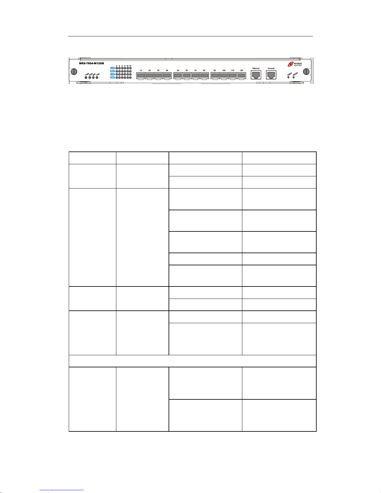
The Front Panel view is shown below:
Fig 1-7 MRS-7604-M12GB Front Panel View
1.4.2.1.2 Front Panel - Indicator
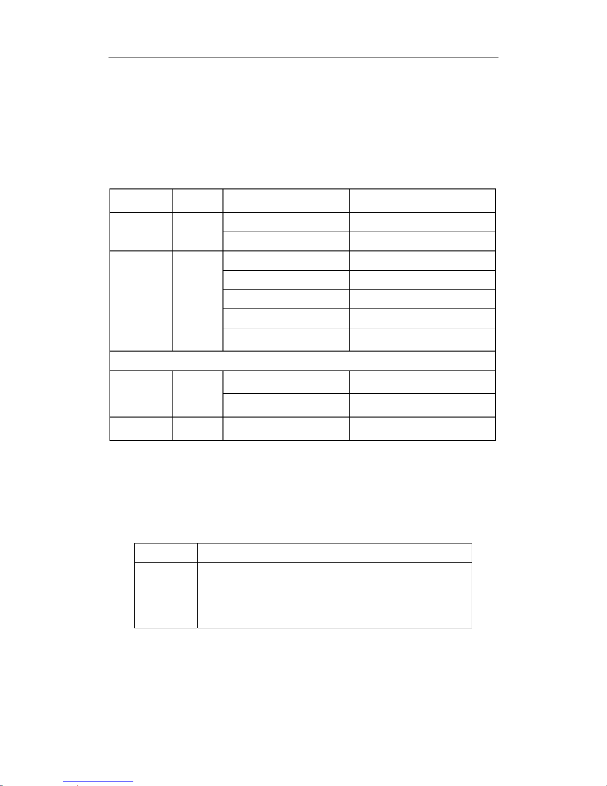
The following table describes the front panel indicators of MRS-7604-M12GB:
Table 1-1 MRS-7604-M12GB indicators description
LED Panel Symbol Status Description
On (Green) Card powered
Power
Indicator
PWR
Off Card powered off
On (Green, blink at 1
Hz)
Cards operating
normally
On (Green, blink at 8
Hz)
System is loading
On (Yellow, blink at 8
Hz)
System is shutting down)
On (Red, blink at 8 Hz) Cards malfunction
Operation
indicator
RUN
Off
Cards are powered off
and can be removed
On (Green) Master
Master-Slave
indicator
M/S
Off Slave
On (Green) Fan operating normally
Fan Assembly
Status
indicator:
FAN
OK
Off
Fan malfunctioning or
not present (with Alarm
off)
SFP port indicator
On (Green)
Network connection on
SFP transceiver is
normal
Status
indicator
Link
Off
No network connection
present on SFP
transceiver
DCRS-7600 InstallManual Chapter 1 Product Overview
1-15
Transmission
Indicator
Act Blinking (Green)
Sending or receiving
data
1.4.2.1.3 Front Panel Port Description
The MRS-7604-M12GB provides 12 SFP (Mini GBIC) Gigabyte fiber transceiver
slots.
The following SFP transceivers are supported by the MRS-7604-M12GB:
z SFP-SX-L Gigabit SFP MM 850 nm, 500m (SX)
z SFP-LX-L Gigabit SFP SM 1310 nm, 10Km (LX)
z SFP-LX-20-L Gigabit SFP SM 1310 nm, 10Km (LX)
z SFP-LX-40-L Gigabit SFP SM 1310 nm, 40Km (LHX)
z SFP-LH-70-L Gigabit SFP SM 1550 nm, 70Km (ZX)
z SFP-LH-120-L Gigabit SFP SM 1550 nm, 120Km (ZX)
z SFP-GT Gigabit SFP to Copper cable RJ45
1.4.2.1.4 Front Panel – Console Port
The MRS-7604-M12GB provides a RJ-45 (receptacle) Console serial port. Users can
connect to hosts via this port to perform system debugging, configuration, maintenance,
management and host software loading.
Table 1-2 MRS-7604-M12GB Console description
Property Specification
Connector
RJ-45 (receptacle)
Connector type
RS-232
Baud rate
9600bps (default)
Supporting service
z Connects to character terminals
z Connects to PC serial port and running terminal emulator
on PC.
1.4.2.1.5 Front Panel – Management Port
The MRS-7604-M12GB provides a RJ-45 (receptacle) Ethernet port. Users can
connect through this management port to hosts for program loading or to connect to
remote devices for remote management (e.g., a managing workstation). Note: when
connecting to the host, a cross-over cable should be used.
Table 1-3 MRS-7604-M12GB management port description
Property Specification
DCRS-7600 InstallManual Chapter 1 Product Overview
1-16
Connector
RJ-45 (Receptacle)
Connector type
z 10/100Mbps auto sensing
z Cat 5 UTP: 300 m
1.4.2.1.6 Front Panel – Reset Button
MRS-7604-M12GB provides a RESET button for resetting the board.
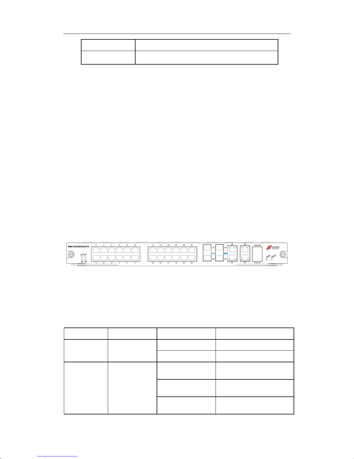
1.4.2.2 MRS-7604-M4GX24TX
The MRS-7604-M4GX24TX is switching module for the DCRS-7604. System status
control, switch management, user access control and management, and network
maintenances are performed here. The board can be inserted into first or second slots of
the chassis for Master-Slave redundancy. 24 10/10Base-TX ports with 4 Gigabit combo
ports (RJ45or SFP) are also provided.
1.4.2.2.1 Front Panel
The MRS-7604-M4GX24TX provides 24 10/100Base-TX ports and 4 Gigabit COMBO
slots. At the same time, it comes with 1 Console port (control console) and 1
10/100Base-Tx Ethernet port (administration port).
The Front Panel view is shown below:
Fig 1-8 MRS-7604-M4GX24TX
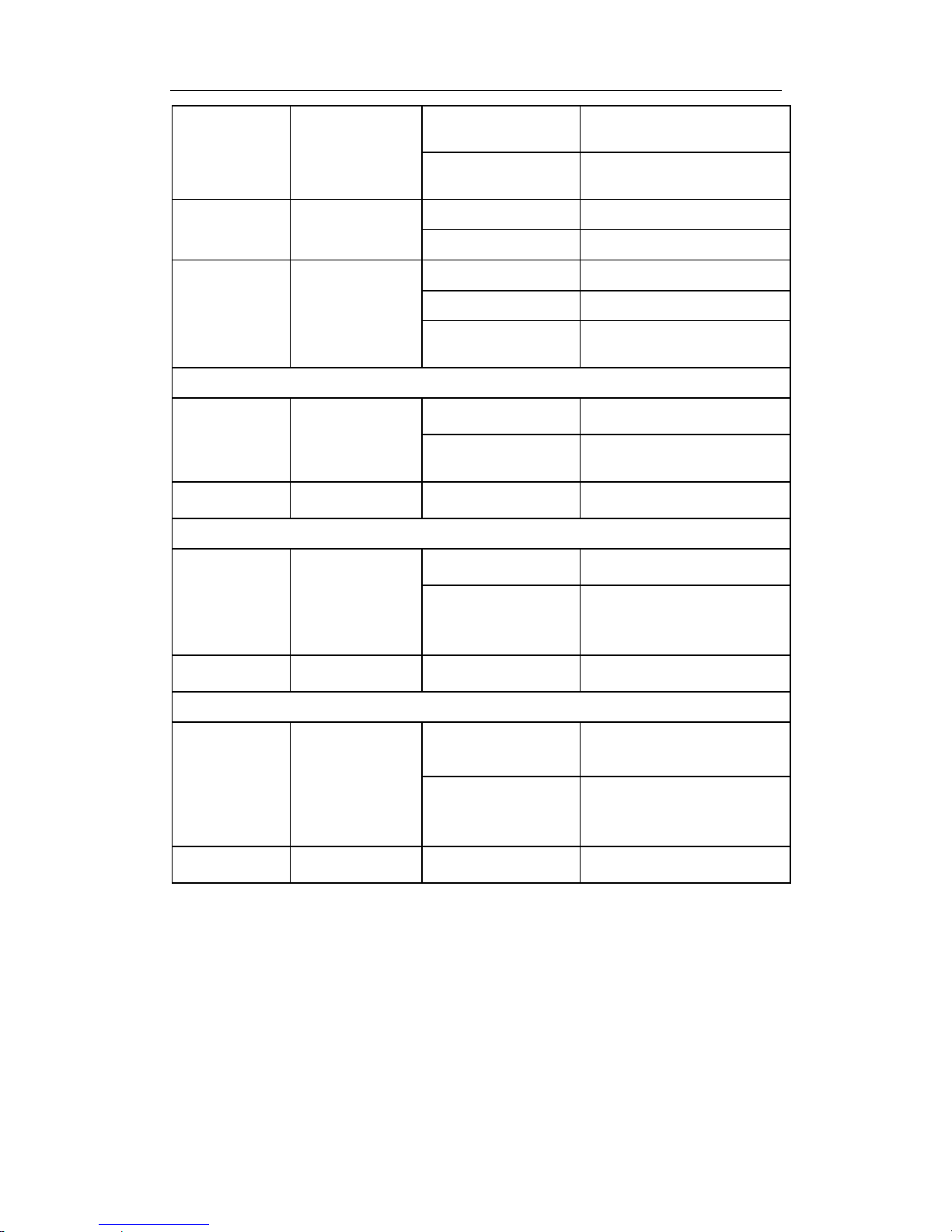
1.4.2.2.2 Front Panel - Indicator
The following table describes the front panel indicators of MRS-7604-M4GX24TX:
Table 1-4 MRS-7604-M4GX24TX indicators description
LED Panel Symbol Status Description
On (Green) Card powered
Power
Indicator
PWR
Off Card powered off
On (Green, blink at 1
Hz)
Cards operating normally
On (Green, blink at 8
Hz)
System is loading
Operation
indicator
RUN
On (Yellow, blink at 8
Hz)
System is shutting down
DCRS-7600 InstallManual Chapter 1 Product Overview
1-17
On (Red, blink at 8
Hz)
Cards malfunction
Off
Cards are powered off and
can be removed
On (Green) Master
Master-Slave
indicator
M/S
Off Slave
On (Green) Fan operating normally
On (Red) Fan malfunctioning
Fan Assembly
Status
indicator:
FAN
FAN
Off
Fan not present (with Alarm
off)
SFP port indicator
On (Green)
Network connection on SFP
transceiver is normal
Status
indicator
Link
Off
No network connection
present on SFP transceiver
Transmission
Indicator
Act Blinking (Green) Sending or receiving data
10/100Base-RJ45 port indicator
On (Green)
Network connection is
normal
Status
indicator
Link
Off
No network connection
present on
10/100Base-RJ45 port
Transmission
Indicator
Act Blinking (Green) Sending or receiving data
1000Base-TX port indicator
On (Green)
Network connection on
1000Base-TX transceiver is
normal
Status
indicator
Link
Off
No network connection
present on 1000Base-TX
transceiver
Transmission
Indicator
Act Blinking (Green) Sending or receiving data
1.4.2.2.3 Front Panel Port Description
The E MRS-7604-M4GX24TX provides 24 10/100Base-TX ports and 4 Gigabite
COMBO (RJ-45 or SFP) transceiver slots.
The following SFP transceivers are supported by the MRS-7604-M4GX2 4TX:
z SFP-SX-L Gigabit SFP MM 850 nm, 500m (SX)
z SFP-LX-L Gigabit SFP SM 1310 nm, 10Km (LX)
z SFP-LX-20-L Gigabit SFP SM 1310 nm, 10Km (LX)
DCRS-7600 InstallManual Chapter 1 Product Overview
1-18
z SFP-LX-40-L Gigabit SFP SM 1310 nm, 40Km (LHX)
z SFP-LH-70-L Gigabit SFP SM 1550 nm, 70Km (ZX)
z SFP-LH-120-L Gigabit SFP SM 1550 nm, 120Km (ZX)
z SFP-GT Gigabit SFP to Copper cable RJ45
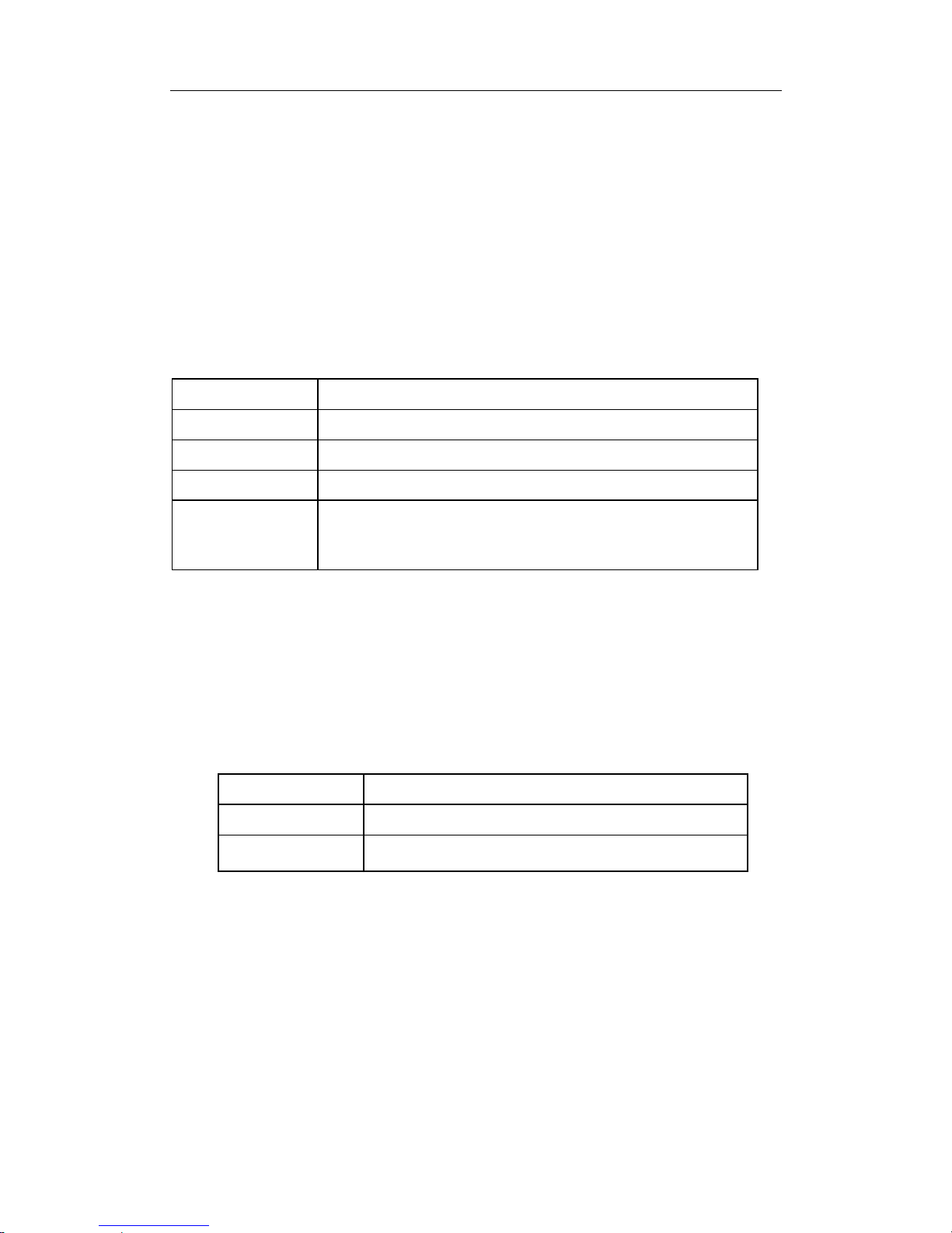
1.4.2.2.4 Front Panel – Console Port
The MRS-7604-M4GX24TX provides a RJ-45 (receptacle) Console serial port. Users
can connect to hosts via this port to perform system debugging, configuration,
maintenance, management and host software loading.
Table 1-5 MRS-7604-M4GX24TX Console description
Property Specification
Connector
RJ-45 (receptacle)
Connector type
RS-232
Baud rate
9600bps (default)
Supporting service
z Connects to character terminals
z Connects to PC serial port and running terminal emulator
on PC.
1.4.2.2.5 Front Panel – Management Port
The MRS-7604-M4GX24TX provides a RJ-45 (receptacle) Ethernet port. Users can
connect through this management port to hosts for program loading or to connect to
remote devices for remote management (e.g., a managing workstation). Note: when
connecting to the host, a cross-over cable should be used.
Table1-6 MRS-7604-M4GX24TX management port description
Property Specification
Connector
RJ-45 (Receptacle)
Connector type
z 10/100Mbps auto sensing
z Cat 5 UTP: 300 m
1.4.2.2.6 Front Panel – Reset Button
MRS-7604-M4GX24TX provides a RESET button for resetting the board.
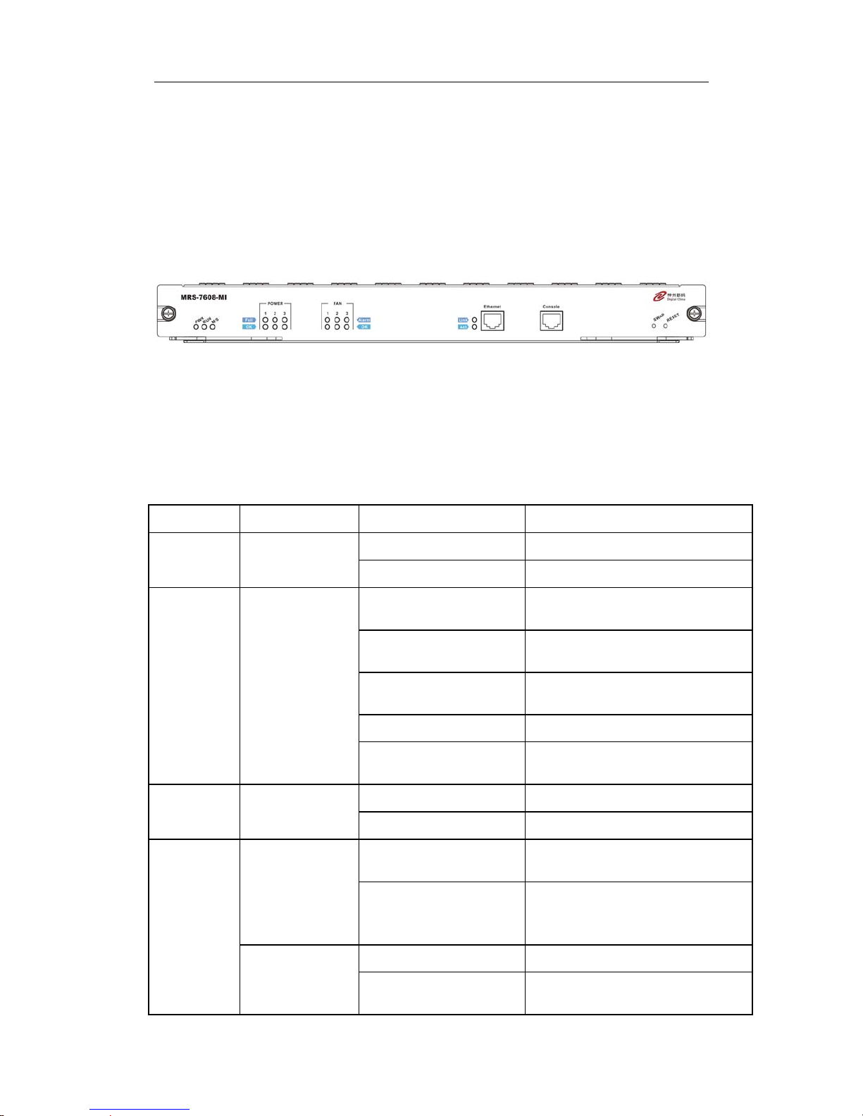
1.4.2.3 MRS-7608-MI
The MRS-7608-MI is switching module for the DCRS-7608. System status control,
switch management, user access control and management, and network maintenances
are performed here. The board can be inserted into M1 or M2 slots of the chassis for
DCRS-7600 InstallManual Chapter 1 Product Overview
1-19
Master-Slave redundancy.
1.4.2.3.1 Front Panel
The MRS-7608-MI comes with 1 Console port (control console) and 1 10/100Base-Tx
Ethernet port (management port).
The Front Panel view is shown below:
Fig 1-9 MRS-7608-MI Front Panel view
1.4.2.3.2 Front Panel - Indicator
The following table describes the front panel indicators of MRS-7608-MI:
Table 1-7 MRS-7608-MI indicators description
LED Panel Symbol Status Description
On (Green) Card powered
Power
Indicator
PWR
Off Card powered off
On (Green, blink at 1
Hz)
Cards operating normally
On (Green, blink at 8
Hz)
System is loading
On (Yellow, blink at 8
Hz)
System is shutting down
On (Red, blink at 8 Hz) Cards malfunction
Operation
indicator
RUN
Off
Cards are powered off and can be
removed
On (Green) Master
Master-Slav
e indicator
M/S
Off Slave
On (Green)
Power Supply Module operating
normally
OK
Off
Power supply module
malfunctioning or not present (with
Fail off)
On (Yellow) Power Supply Module malfunction
Power
Supply
Module
Status
indicator:
POWER
Fail
Off
Power supply module operating
normally or not present (with OK
DCRS-7600 InstallManual Chapter 1 Product Overview
1-20
off)
On (Green) Fan operating normally
OK
Off
Fan malfunctioning or not present
(with Alarm off)
On (Yellow) Fan malfunction
Fan
Assembly
Status
indicator:
FAN
Alarm
Off
Fan operating normally or not
present (with OK off)
1.4.2.3.3 Front Panel – Console Port
The MRS-7608-MI provides a RJ-45 (receptacle) Console serial port. Users can
connect to hosts via this port to perform system debugging, configuration, maintenance,
management and host software loading.
Table 1-8 MRS-7608-MI Console description
Property Specification
Connector
RJ-45 (receptacle)
Connector type
RS-232
Baud rate
9600bps (default)
Supporting service
z Connects to character terminals
z Connects to PC serial port and running terminal emulator
on PC.
1.4.2.3.4 Front Panel – Management Port
The MRS-7608-MI provides a RJ-45 (receptacle) Ethernet port. Users can connect
through this management port to hosts for program loading or to connect to remote
devices for remote management (e.g., a managing workstation). Note: when connecting
to the host, a cross-over cable should be used.
Table 1-9 MRS-7608-MI management port description
Property Specification
Connector
RJ-45 (Receptacle)
Connector type
z 10/100Mbps auto sensing
z Cat 5 UTP: 300 m
1.4.2.3.5 Front Panel – Reset Button
MRS-7608-MI provides a RESET button for resetting the board.
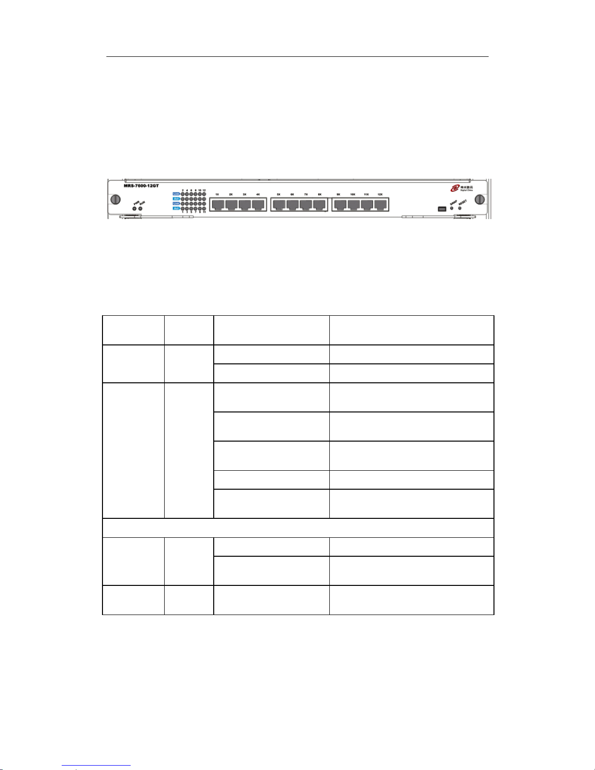
1.4.2.4 MRS-7600-12GT
DCRS-7600 InstallManual Chapter 1 Product Overview
1-21
12 copper GT ports line card (MRS-7600-12GT): supports 12 1000Base-T copper
ports for layer 2 and layer 3 switching and routing.
1.4.2.4.1 Front Panel
MRS-7600-12GT provides 12 RJ45 ports (10/100/1000Mbps adaptive).
The Front Panel view is shown below:
Fig 1-10 MRS-7600-12GT Front Panel view
1.4.2.4.2 Front Panel - Indicator
The following table describes the MRS-7600-12GT’s front panel indicators:
Table 1-10 MRS-7600-12GT indicator descriptions
LED
Panel
Symbol
Status Description
On (green) Card powered
Power
Indicator
PWR
Off Card powered off
On (Green, blinks at 1
Hz)
Card operating normally
On (Green, blinks at 8
Hz)
System is loading
On (Yellow, blinks at 8
Hz)
System is shutting down
On (Red, blinks at 8 Hz) Malfunction status
Operation
indicator
RUN
Off
Card is powered off and can be
removed
RJ-45 port indicator
On (Green) Network connection is normal
Status
indicator
Link
Off
No network connection present on
1000Base-TX port
Transmissio
n Indicator
Act Blinking (Green) Sending or receiving data
1.4.2.4.3 Front Panel Port Description
The MRS-7600-12GT provides 12 RJ45 copper GT ports.
Table 1-11 MRS-7600-12GT port description
DCRS-7600 InstallManual Chapter 1 Product Overview
1-22
Port Type Specification
RJ-45 port
z 10/100/1000 Mbps auto sensing
z MDI/MDI-X cable ant sensing
z Cat 5 UTP: 100 m
1.4.2.4.4 Front Panel – Reset Button
The MRS-7600-12GT provides a RESET button for resetting the board.
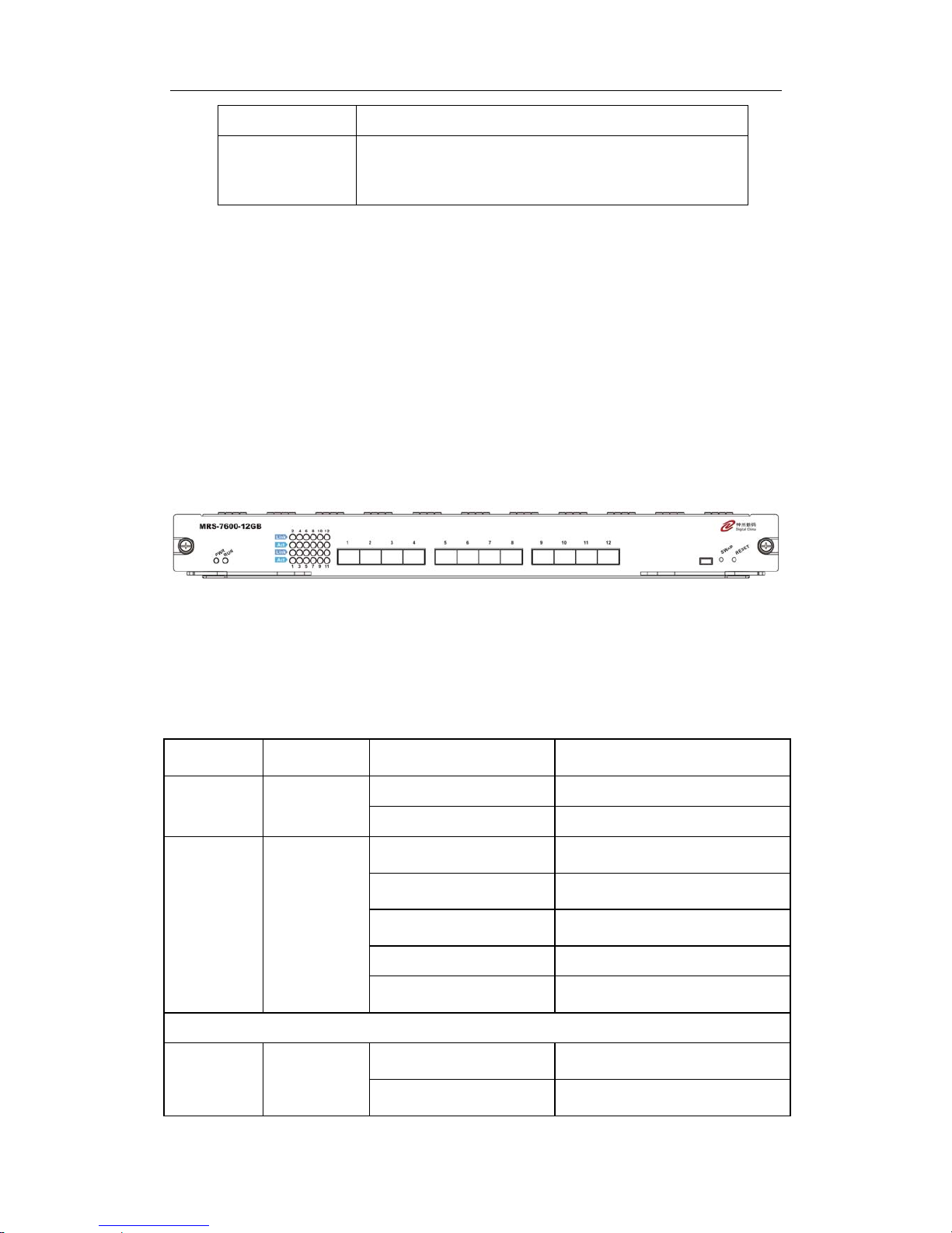
1.4.2.5 MRS-7600-12GB
12 fiber GB ports line card (MRS-7600-12GB): supports 12 SFP GB fiber ports for
layer 2 and layer 3 switching and routing.
1.4.2.5.1 Front Panel
MRS-7600-12GB provides 12 SFP ports. The Front Panel view is shown below:
Fig 1-11 MRS-7600-12GB Front Panel view
1.4.2.5.2 Front Panel - Indicator
The following table describes the MRS-7600-12GB’s front panel indicators:
Table 1-12 MRS-7600-12GB indicator descriptions
LED
Panel
Symbol
Status Description
On (green) Card powered
Power
Indicator
PWR
Off Card powered off
On (Green, blinks at 1
Hz)
Cards operating normally
On (Green, blinks at 8
Hz)
System is loading
On (Yellow, blinks at 8
Hz)
System is shutting down
On (Red, blinks at 8 Hz) Malfunction status
Operation
indicator
RUN
Off
Cards is powered off and can be
removed
SFP port indicator
On (Green)
Network connection on SFP
transceiver is normal
Status
indicator
Link
Off
No network connection present
on SFP transceiver

DCRS-7600 InstallManual Chapter 1 Product Overview
1-23
Transmissio
n Indicator
Act Blinking (Green) Sending or receiving data
1.4.2.5.3 Front Panel Port Description
The MRS-7600-12GB provides 12 SFP (Mini GBIC) Gigabyte fiber transceiver slots.
The following SFP transceivers are supported by the MRS-7600-12GB:
z SFP-SX-L Gigabit SFP MM 850 nm, 500m (SX)
z SFP-LX-L Gigabit SFP SM 1310 nm, 10Km (LX)
z SFP-LX-20-L Gigabit SFP SM 1310 nm, 10Km (LX)
z SFP-LX-40-L Gigabit SFP SM 1310 nm, 40Km (LHX)
z SFP-LH-70-L Gigabit SFP SM 1550 nm, 70Km (ZX)
z SFP-LH-120-L Gigabit SFP SM 1550 nm, 120Km (ZX)
z SFP-GT Gigabit SFP to Copper cable RJ45
1.4.2.5.4 Front Panel – Reset Button
The MRS-7600-12GB provides a RESET button for resetting the board.
1.4.2.6 MRS-7600-1-10GX and MRS-7600-2-10GX
Single 10GbE fiber line card (MRS-7600-1-10GX): supporting 1 XENPAK 10Gb fiber
port for layer 2 and layer 3 switching and routing.
Dual 10GbE fiber line card (MRS-7600-2-10GX): supporting 2 XENPAK 10Gb fiber
port for layer 2 and layer 3 switching and routing.
1.4.2.6.1 Front Panel
The MRS-7600-1-10GX provides 1 XENPAK 10GB fiber transceiver ports, the front
panel view is shown below:
Fig
1-12 MRS-7600-1-10GX front panel view
The MRS-7600-2-10GX provides 2 XENPAK 10GB fiber transceiver ports, the front
panel view is shown below:
DCRS-7600 InstallManual Chapter 1 Product Overview
1-24
Fig
1-13 MRS-7600-2-10GX front panel view
1.4.2.6.2 Front Panel - Indicator
The following table describes the front panel indicators for the MRS-7600-1-10GX
and MRS-7600-2-10GX:
Table 1-13 Description of the MRS-7600-1-10GX 、MRS-7600-2-10GX indicators
LED
Indicator
Panel
Symbol
Status Description
On (green) Card powered.
Power
Indicator
PWR
Off Card powered off
On (Green, blinks at 1 Hz) Card operating normally
On (Green, blinks at 8 Hz) System is loading
On (Yellow, blinks at 8 Hz) System is shutting down
On (Red, blinks at 8 Hz) Malfunction status
Operation
indicator
RUN
Off
Card is powered off and can be
removed.
XENPAK port indicator
On (Green)
Network connection on
XENPAK transceiver is normal
Status
indicator:
Link
Off
No network connection present
on XENPAK transceiver
Transmissio
n Indicator
Act Blinking (Green) Sending or receiving data
1.4.2.6.3 Front Panel Port Description
MRS-7600-1-10GX 、 MRS-7600-2-10GX provides 1 or 2 XENPAK 10Gb fiber
transceiver slots;
Table 1-14 XENPAK port descriptions
Port Type Specification
XENPAK
z XENPAK-SC transceiver (10GBASE-LR LAN-PHY)
(Agilent HFCT-701XB, LAN mode, wavelength 1310nm):
62.5/125 µm multi-mode fiber (MMF): 300m
9/125 µm single-mode fiber (SMF): 10Km
1.4.2.6.4 Front Panel – Reset Button
The MRS-7600-1-10GX 、MRS-7600-2-10GX provides a RESET button for resetting
the board.
 Loading...