


DCRS-7600E InstallManual Content
1
Content
CHAPTER 1 PRODUCT OVERVIEW ......................................... 1-1
1.1 PRODUCT BRIEF ................................................................................. 1-1
1.1.1 Introduction ........................................................................................... 1-1
1.1.2 Main Features ........................................................................................ 1-2
1.2 TECHNICAL SPECIFICATIONS ................................................................. 1-2
1.3 PHYSICAL SPECIFICATIONS .................................................................. 1-6
1.4 HARDWARE COMPONENTS ................................................................... 1-6
1.4.1 Chassis .................................................................................................. 1-6
1.4.2 Introduction to DCRS-7600E Series Cards ....................................... 1-14
1.4.3 Interface description ........................................................................... 1-47
1.4.4 Power supply ...................................................................................... 1-48
1.4.5 Power Distribution Box ...................................................................... 1-52
1.4.6 System Backplane .............................................................................. 1-53
1.4.7 Fan Tray ............................................................................................... 1-54
1.4.8 Dust Gauze .......................................................................................... 1-56
1.4.9 Rear Panel ........................................................................................... 1-57
1.4.10 Side Panels ........................................................................................ 1-59
1.5 SYSTEM FEATURES ........................................................................... 1-61
1.5.1 DCRS-7604E System Features .......................................................... 1-61
1.5.2 DCRS-7608E System Features .......................................................... 1-62
CHAPTER 2 HARDWARE INSTALLATION ............................... 2-1
2.1 INSTALLATION NOTICE ......................................................................... 2-1
2.1.1 Basic Requirements ............................................................................. 2-1
2.1.2 Safety Guidelines .................................................................................. 2-4
2.1.3 Safety Warning ...................................................................................... 2-5
2.1.4 Hot Line Work Safety Guidelines ......................................................... 2-5
2.2 PREPARING FOR INSTALLATION ............................................................. 2-6
2.2.1 Checking Switch Hardware Configuration and Accessories ............ 2-6
2.2.2 Required Tools and Fixings ................................................................. 2-6
2.3 HARDWARE INSTALLATION ................................................................... 2-7
2.3.1 Switch Installation ................................................................................ 2-7
2.3.2 Switch grounding ................................................................................ 2-12
2.3.3 Card and module installation ............................................................. 2-13
2.3.4 Connecting to the Console ................................................................ 2-21
2.3.5 Connecting to the Management Port ................................................ 2-21
2.3.6 SFP transceiver installation ............................................................... 2-22
2.3.7 Copper Cable/Fiber Cable Connection ............................................. 2-22
2.3.8 Power supply connection .................................................................. 2-23
DCRS-7600E InstallManual Chapter 1 Product Overview
1-1
Chapter 1 Product Overview
RECOMMENDATION: Please read this manual f irst before using the switch,
following the instructions to avoid damaging the device.
1.1 Product Brief
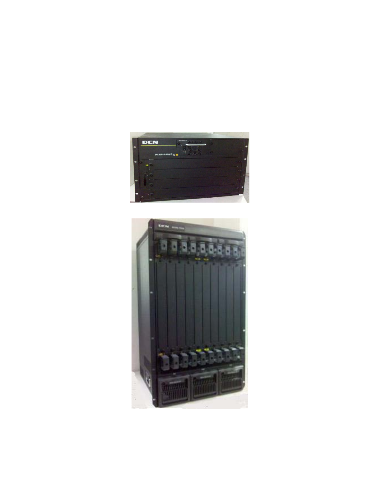
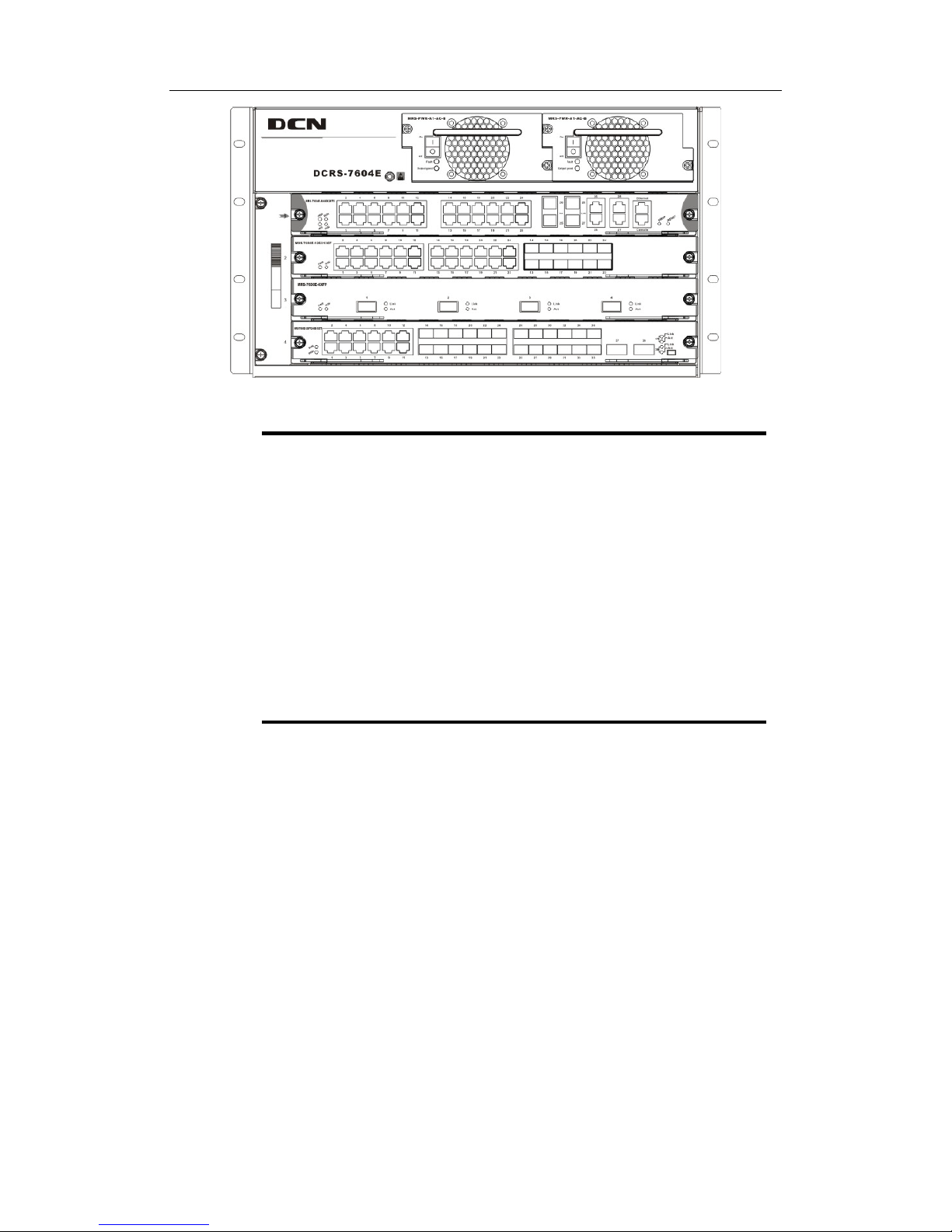
FIG
1-1 DCRS-7604E Switch
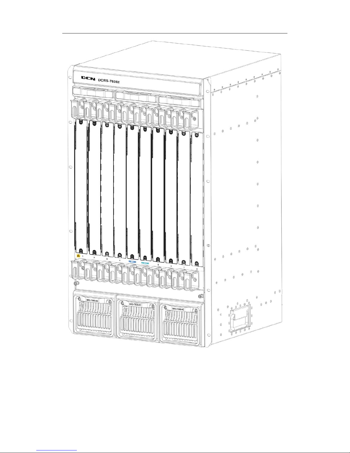
FIG 1-2 DCRS-7608E Switch
1.1.1 Introduction

DCRS-7600E InstallManual Chapter 1 Product Overview
1-2
Digital China DCRS-7600E series is a high performance routi ng switch that can be
deployed as a core layer device for campus and enterprise networks, or an aggregation
device for IP metropolitan area networks (MAN).
DCRS-7604E provides 4 slots. DCRS-7608E provides 10 slots, 8 of which are
interface module slots.
DCRS-7600E series supports various types of line cards, and can seamlessly
support network interfaces from 100Mb, 1000Mb to 10G B Ethernet. Featuring functions
such as policy-based routing, IPv6, and load balance, it is capable of flexibly meeting the
different requirements of complex customer environments. Furthermore, DCRS-7600E
series allows redundancy for management modules, power supply. It supports both
AC-input and DC-input* power supplies, with hot-swapping support for cards, power
supplies and fans. The working temperature of all cards can be monitored in real-time,
offering carrier-class reliability.
1.1.2 Main Features
DCRS-7604E 4 slots that can be configured in Primary controller-Primary Backup
mode with 2 management modules and 2 network modules, or Single controller mode
with one management module and 3 network modules.
DCRS-7608E 10 slots that c an be configured in Primary controller-Primary Backup
mode with 2 management modules and 8 network modules, or Single controller mode
with one management module and 8 network modules.
The management modules of DCRS-7604E have network interfaces, and then all the
slots are effective network slots.
Store-and-forward switching, ensuring minimal latency.
Auto MDI/MDI-X, enabled on all RJ-45 ports, allows connections to other switches
using a non-crossover twisted pair cable.
Full-duplex IEEE802.3x flow control, half-duplex backpressure flow control.
Console management port provided.
Port working status and statistics available.
Restart and reset to factory setting can be done both locally and remot ely.
TFTP /FTP firmware upgrade available.
Can be installed into standard 19-inch chassis.
1.2 Technical specifications
Item
DCRS-7604E
DCRS-7608E
Slot
4
10
DCRS-7600E InstallManual Chapter 1 Product Overview
1-3
Port
10/100/1000BASE-T, 192 at best
1000Base-SX, 192 at best
1000Base-LX, 192 at best
10/100BASE-T, 192 at best
10GBase, at best
10/100/1000BASE-T, 384 at best
1000Base-SX, 384 at best
1000Base-LX, 384 at best
10/100BASE-T, 384 at best
10GBase, at best
Backboard
bandwidth
1.2Tbps(can extend to 2.4Tbps) 2.4Tbps(can extend to 4.8Tbps)
Exchange
capacity
640Gbps
1.28Tbps/2.4Tbps (the secon
d
generation engine)
Packet
Forwarding
Speed
476Mpps
952Mpps/1785Mpps
(the second
generation engine)
Forwarding Delay
Time among Ports
<=6ms <=6ms
VLAN Item
4K
4K
Layer 2 Protocol
Specifications
IEEE802.3(10Base-T), IEEE802.3u(100Base-TX), IEEE802.3z(1000BASE-X)
,
IEEE802.3ab(1000Base-T), IEEE802.3ae(10GBase), IEEE802.1Q(VLAN)
,
IEEE802.3ak(10GBASE-CX4), IEEEE802.1d(STP), IEEEE802.1W(RSTP),
IEEEE802.1S(MSTP), IEEE802.1p(COS), IEEE802.1x(Port Control)
,
IEEE802.3x(Flow control), IEEE802.3ad(LACP), Port Mirror, RSPAN, ULDP
,
LLDP, IGMP Snooping, QinQ, GVRP, VLAN, PVLAN, VOICE VLAN,
Protocol
Vlan, Multicast VLAN, Mac Vlan, Broadcast Storm Control
Layer 3 Protocol
Specifications
(IPv4)
Support ARP, ARP Proxy, ARP Limiting Speed, ARP Repeat-Authentication,
Gratuitous ARP
Support DNS client
Support Static Routing, RIPv1/v2, OSPFv2, BGP4, GRE
Unicast Routing Protocol
etc.
Support Routings for OSPF’s different process import each other
Support LPM Routing, Policy-based Routing(PBR), ECMP
Support VRRP, URPF, Black Hole Routing
Support IGMP v1/2/3, DVMRP, PIM-DM, PIM-SM, PIM-SSM, IGMP Proxy
,
anycast RP, MSDP, Static multicast Routing, boundary multi cast Routing etc.
Strengthen
Extend
Support in-embed firewall, IDS, IPSce VPN, Content-exchange service,
Network
Analysis hardware module etc.
Free-Resource
Support

DCRS-7600E InstallManual Chapter 1 Product Overview
1-4
IPv6
Support ICMPv6, ND, DNSv6
Support IPv6 LPM Routing, IPv6 Policy-based Routing(PBR)
Support IPv6 VRRPv3, IPv6 URPF, IPv6 Black Hole Routing
Support RIPng, OSPFv3, BGP4+ Unicast Routing Protocol etc.
Support 6to4 Tunnels, configured Tunnels, ISATAP etc.
Support MLD Snooping, IPv6 Muticast VLAN
Support MLDv1/v2, PIM-SM/DM for IPv6, IPv6 anycast RP,
IPv6 Static multicast
Routing, IPv6 boundary multicast Routing, IPv6 multicast tunnel etc.
Support IPv6 ACL, IPv6 QOS
Strengthen
ARP/NDP Safety
function
Support ARP/NDP Spoofing Prevention, ARP/NDP Scanning Prevention
MPLS
MPLS, LDP, MPLS VPN, MPLS TE, Access public network technology
QoS
Carry out by hardware completely, have no effect for performance.
Each port has 8 queues. Support SP, WRR, SWRR queue scheduling algorithm.
Support traffic class base on 802.1p, ToS, port, DiffServ
Class traffic by ACL;
configure the COS, TOS, DSCP bases class result. Class
traffic by high-layer content for ACL-X’s 80 bytes
Support SP, WRR,
SWRR etc. Provide different service quality requested for
speech, data and video transmit at the same network.
Support Traffic Shaping
Support priority Mark/Remark
ACL
Carry out by hardware completely, have no effect for forwarding performance.
Support Standard ACL and Extended ACL
Support IP ACL, base on IP-subnet ACL, MAC ACL, IP-MAC ACL,
Support IP or MAC based on source/destination, Layer 3 IP protocol type
,
TCP/UDP layer 4 port number, IP priority (DSCP, ToS, Precedence),
base on
VLAN, Tag/Untag, CoS etc.
Support REDIRECT based on ACL, Traffic statistic based on ACL
ACL-X
Support to transfer security policy automaticall y base on t i me.
ACL’s deepness content can be used for QoS sort standard, the deepness can
extend 80 bytes.
DCSCMv4/v6
Support IPv4/IPv6 Multicast Source Controllable
, Prevent lawless Multicast
Source
Support IPv4/IPv6 multicast user Controllable
Support IPv4/IPv6 policy multicast
DCRS-7600E InstallManual Chapter 1 Product Overview
1-5
Port Function
Support MAC+ port binding, IP+ MAC+ port binding, IP+ port binding
Support MAC filter
Support Port Limit(bandwidth management)
Support Port Loopback Detection
Support Port Mirror(CPU Port Mirror, ingress or egress unilateralism/
bidirectional, one-to-one, many-to-one, stride board, stride equipment),
Support Flow Control: HOL prevent head-packet block, half-
duplex back
pressure, full-duplex IEEE802.3x
Support Port aggregation IEEE802.3ad(LACP), port-to-port GEC/FEC,
each
trunk can up to 8 ports, support load equipoise
DHCPv4/v6
Support IPv4/IPv6 DHCP Client, IPv4/IPv6 DHCP Relay,
IPv4/IPv6 DHCP
Snooping
Inside-install IPv4/IPv6 DHCP Server, DHCP Option82
Security Access
Support IEEE 802.1x, DCSM
AAA
Authentication
Support IPv4/IPv6 RADIUS
Security Function
Configuration
Support IPv4/IPv6 syslog
Support the unite for IPv4/IPv6 HTTP and SSL
Support the user IP security inspection for IPv4/IPv6 SNMP
Support MIB and TRAP
Support IPv4/IPv6 FTP/TFTP
Support IPv4/IPv6 NTP
Support RMOM 1, 2, 3, 9 four group
Support the RADIUS authentication for IPv4/IPv6 telnet user name and password
Support IPv4/IPv6 SSHs
The right configuration for users can adopt radius serve r’s shell management
Support the function for timing-reset bases needs
sFlow Function
Support network flow analysis,Support RFC3176,
can realize the flow monitoring
and statistic based on protocol or address
IPFIX
A standard protocol can measure the flow information of the IETE network
Exception
monitoring and
fault check-up
Monitoring the Task exception, Memory exception, CPU utilance, Stack
exception, Switching-
chip exception, board temperature exception etc. And
giving an alarm
Centralized W
eb
Management
Software
It is adopted the Digital China centralized web management software
‘LinkManager’ for unified management.

DCRS-7600E InstallManual Chapter 1 Product Overview
1-6
1.3 Physical Specifications
Management Port
□ One RJ-45 serial port for each management modul e
AC Power Input
□ Input: 90~264V, 50 ~ 60Hz
□ Built-in Universal Power Supply
DC Power Input
□ Input: -36V~ -72VDC
□ Built-in Universal Power Supply
Power Consumption
□ DCRS-7604E: 400W Max
□ DCRS-7608E: 1200W Max
Operating Temperature
□ 0°C ~ 45°C
Storage Temperature
□ -40°C ~ 70°C
Relative humidity
□ 10% ~ 90% with no condensate
Dimension
□ DCRS-7604E 440mm×266mm×421mm (W x H x D)
□ DCRS-7608E 436mm×797mm×478mm (W x H x D)
Weight
□ DCRS-7604E: 30kg (max. full configuration wei ght)
□ DCRS-7608E: 65kg (max. full configuration weight)
Mean Time Before Failure
□ Min. 80,000 Hours MTBF
1.4 Hardware Components
DCRS-7604E consists of the chassis, power supply system, ventilation system,
system board, etc.
1.4.1 Chassis
1.4.1.1 DCRS-7604E Chassis
DCRS-7600E InstallManual Chapter 1 Product Overview
1-7
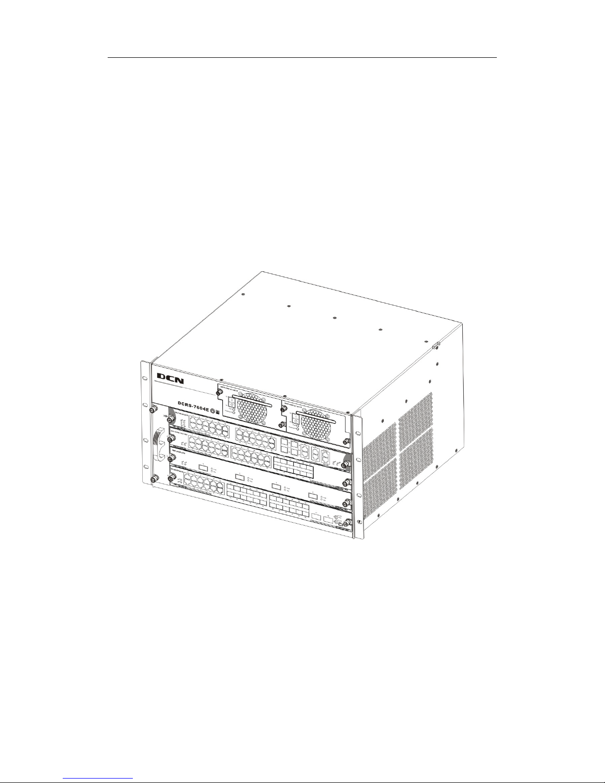
The DCRS-7604E uses a 19-inch Rack Mountable Chassis, with the standard
dimensions of 440mm (W) x 266mm (H) x 421mm (D). The chassi s consists of functional
block and power supply block. The function module bl ock is a board rack, which is the
supporting structure for DCRS-7604E system boards (4 boards max). The fan block is
located on the left side of the board rack, allowing one fan tray (4 axial f ans for each fan
tray). Dust gauze is provided on the right of the board rack for filtering air circulation
through the rack. The power block upper the dust gauze provid es power to the system,
supporting up to two power modules. The po wer modules insert int o the power sl ots from
the front, with the distribution box at the back of the rack for maintenance.
In addition, there is an ESD Wrist Strap Connectors on the board rack, located on the
left side of the upper.
Fig 1-3 DCRS-7604E Module Outlook
DCRS-7600E InstallManual Chapter 1 Product Overview
1-8
Fig 1-4 DCRS-7604E Front Panel View
① Management slot: It supports two management slots.
MRS-7604E-M1XFP12GX12GB or MRS-7604E-M44GT etc.can be
inserted in to the Management slots.The second slot can als o be used
as I/O slot for configuring various I/O modules.
② Network slot: 2 network slots are provided. Various network modules
can be added to the network slots. Such as MRS-7600E-4XFP and
MRS-7600E-12GX12GT etc.
③ Power slot: Used for system power supply modules. Support up to two
400W AC/DC modules.
④ Fan tray slot: Supports up to one system fan assemblies, each
assembly consists of four axial fans.
⑤ Dust gauze slot: Exterior air inlet for the ventilation subsystem.
⑥ Distribution box slot: For system distribution box use, works in AC
mode based on the power modules.
1.4.1.1.1 Board Rack
The board rack consists of board slots and a system board.
The boards are inserted vertically into t he DCRS-7604E 4 unit boards are provided.
There are four slots in DCRS-7604E from number 1 to number 4 in order of top to down.
The first slot is used to install management module; the second slot is used to
management module under 1+1 redundant backup mode or i nstall various I/O interface
modules.
A reset button (printed on the panel as Reset), hot swap button (printed on the panel
as SWAP), board power indicator (printed on the panel as PWR) and board running status
indicator (printed on the panel as RUN) are provided for each board. On t he Main Control
cards there is Master-Slave indicator (printed on the panel as M/S) T here is also a power
module status indicator (printed on the panel as Power), fan assembly status indicator
(printed on the panel as Fan), and interface status indicators for corresponding

DCRS-7600E InstallManual Chapter 1 Product Overview
1-9
management interfaces and network interfaces (print ed on the panel as Link and Act).
The DCRS-7604E system board is an essential part of the switch, located inside t he
switch and providing interconnectivity between the management switch modules (short for
management card) and network interface modules (line card), and for all management
and control signals.
1.4.1.1.2 Power Supply
When using A.C. power supply, we shall adopt power supply of 110V/220V and
corresponding A.C. distribution box. The permissible range of power supply is 90~
264VAC, 50~60Hz. The maximum output power of single power supply module is 400W.
When using D.C. power supply, we shall adopt power supply of -48V and
corresponding D.C. distribution box. The permissible range of power supply is -36V~
-72VDC. The maximum output power of single power supply module is 400W.
1.4.1.1.3 Ventilation and Cooling System
The operating ambient temperature of the DCRS-7604E is 0 ~ 45°C, the thermal
design of the equipment can ensure that the surface tem perature of the device will not
exceed 50-80% of the highest temperature allowable.
The switch uses fan assemblies to disperse heat, with the air flow being drawn in
through the right section and out through the left section to facilitate air circulation, s o that
the switch can maintain normal operation under specified environmental conditions . The
fan tray is attached to the fan tray slots left the board rack, and ventilation is provided via 4
axial fans that pump out air. Fan trays are hot swappable for maintenance, their status are
indicated by the FAN indicators on the main switch panel. In addition, dust gauze is
provided on the right of the board rack for filtering the air circulating through the rack. The
dust gauze can be unplugged and removed through the back for maintenance.
1.4.1.2 DCRS-7608E Chassis
The DCRS-7608E uses a 19-inch Rack Mountable Chassis, with the standard
dimensions of
436mm (W) x 797mm (H) x 478mm (D). The chassis consists of functional
block, thermal block, and power supply block.
The function module block is a board rack, which is the supporting structure for
DCRS-7608E system boards (10 boards max). Ten wiring clips are provided in the upper
and lower parts of the board rack respectively, for the positioning of all kinds of cables. In
addition, there are two ESD Wrist Strap Connectors on t he board rack, located on the left
side of the upper and lower rack respectively.
The thermal block is located on the upper part of the board ra ck, allowing three fan

DCRS-7600E InstallManual Chapter 1 Product Overview
1-10
trays (2 axial fans for each fan tray). Dust gauze is provided under the board rack for
filtering air circulation through the rack.
The power block under the dust gauze provides power to the system, supporting up
to three power modules. The power modules insert into the power slots from the front, with
the distribution box at the back of the rack for maintenance. Closely beside the distribution
box, a grounding post has been provided on each side of the rack for grounding
connections.
In addition, on both sides of the lower section of the chassis, a handler is provided for
easier transport.
DCRS-7600E InstallManual Chapter 1 Product Overview
1-11
Fig
1-5 DCRS-7608E Module Outlook

DCRS-7600E InstallManual Chapter 1 Product Overview
1-12
Fig 1-6 DCRS-7608E Front Panel view

DCRS-7600E InstallManual Chapter 1 Product Overview
1-13
① Management slot: 2 management slots are provided. One or two
management switching modules MRS-7608E-MI can be inserted in to
the Management slots.
② Network slot: 8 network slots are provided. Various network modules
can be added to the network slots, such as MRS-7600E-48GB,
MRS-7600E-4XFP, etc.
③ Power slot: Used for system power supply modules. Supports up to
three 600W AC modules or three 600W DC modules.
④ Fan tray slot: Supports up to three system fan assemblies, each
assembly consists of two axial fans.
⑤ Dust gauze slot: exterior air inlet for the ventilation subsystem.
⑥ Distribution box slot: For system distribution box use, works in AC/DC
mode based on the power modules.
1.4.1.2.1 Board Rack
The board rack consists of board slots and a system board.
The boards are inserted vertically into the DCRS-7608E 10 unit boards are provided.
These include 2 management slots in the middle for management switch modules,
marked specially in red as M1 and M2. The other eight board slots are network slots for
various network interface modules, sequenced as 1 to 8 from left to right.
A reset button (printed on the panel as Reset), hot swap button (printed on the panel
as SWAP), board power indicator (printed on the panel as PWR) and board running status
indicator (printed on the panel as RUN) are provided for each board. On the Main Control
cards there is Master-Slave indicator (printed on the panel as M/S) There is also a power
module status indicator (printed on the panel as Power: Fail/OK), fan assembly status
indicator (printed on the panel as Fan: Alarm/OK), and interface status indicators for
corresponding management interfaces and network interfaces (printed on the panel as
Link and Act).
The DCRS-7608E system board is an essential part of the switch, located inside the
switch and providing interconnectivity between the management switch modules (short for
management card) and network interface modules (line card), and for all management
and control signals.
1.4.1.2.2 Power Supply
When powered by AC sources, the 110V/220 VAC input power supplies and
corresponding AC distribution box should be use d. The acceptable input power ranges
from 90 ~ 264 VAC at 50 ~ 60 Hz. The maximum output power of each power module is
600W.

DCRS-7600E InstallManual Chapter 1 Product Overview
1-14
When powered by DC sources, the -48 VDC input power suppl y and corresponding
DC distribution box should be used. The acceptable input power ranges from -36 V ~ 72
VDC. The maximum output power of each power module is 600W.
1.4.1.2.3 Ventilation and Cooling System
The operating ambient temperature of the DCRS-7608E is 0 ~ 45°C, the thermal
design of the equipment can ensure that the surface tem perature of the device will not
exceed 50-80% of the highest temperature allowable.
The switch uses fan assemblies to disperse heat, with the air flow being drawn in
through the bottom section and out through the upper section to facilitate air circulation, so
that the switch can maintain normal operation under specified environmental condit ions.
Three fan trays are attached to the fan tray slots above the board rack, and ventilation is
provided via 6 axial fans that pump out air. Fan trays are hot swappable for maintenance,
their status are indicated by the FAN indicators on the main switch panel. In addition, dust
gauze is provided under the board rack for filtering the air circulating through the rack. The
dust gauze can be unplugged and removed through the front for maintenance.
1.4.2 Introduction to DCRS-7600E Series Cards
The following eleven cards for the DCRS-7600E series are currently available:
Main control card (MRS-7604E-M4GX24TX): The central switching and
controlling module for the DCRS-7604E, System status control, switch
management, user access control and administration, and network operation
maintenance are performed here. 24 10/10Base-TX ports with 4 Gigabit combo
ports (RJ45 or SFP) are also provided.
Main control card (MRS-7608E-MI): The central switching and controlling
module for the DCRS-7608E. System status control, switch management, user
access control and administration, and network operation maintenance are
performed here.
4 Gigabit Combo ports and 24 100/10 Base-TX ports line card
(MRS-7600E-4GX24TX): supporting 4 Gigabit Combo ports and 24 100/10
Base-TX ports for layer 2 and layer 3 switching and routing.
12 Gigabit Combo ports and 12 copper GT ports (MRS-7600E-12GX12GT):
supporting 12 Gigabit Combo ports and 12 copper GT ports for layer 2 and layer
3 switching and routing and ipv6 wire speed forward.
Dual 10G XFP ports, 12 Gigabit Combo ports and 12 copper Gb ports
(MRS-7600E-2XFP12GX12GT): supporting dual 10G XFP ports, 12 Gigabit

DCRS-7600E InstallManual Chapter 1 Product Overview
1-15
Combo ports and 12 copper GT ports f or layer 2 and layer 3 switching , routing
and IPv6 wire speed forward.
48 copper GT ports line card (MRS-7600E-48GT): supporting 48 1000Base-T
copper ports for layer 2 and layer 3 switchi ng and routing and IPv6 wire speed
forward.
Main control card (MRS-7604E-M1XFP12GX12GT): The central switching and
controlling module for the DCRS-7604E, System status control, switch
management, user access control and administration, and network operation
maintenance are performed here. The board can be insert ed into f irst or second
slots of the chassis for Master-Slave redundancy, and supports IPv6 wire speed
transmission function. 12-port 1G optical-electronic combo, 12-port 1G
electronic and 1-port 10G XFP interface.
40G XFP interface line card (MRS-7600E-4XFP): implements 2-layer and
3-layer wire-speed switching and routing function of 4 10,000Mbps XFP
interfaces and IPv6 wire-speed transmiss i on.
48 copper GT ports line card (MRS-7600E-48GB): implements 2-layer and
3-layer wire-speed switching and routing function of 48 1000Mbps optical
interfaces and IPv6 wire-speed transmission.
Main control card (MRS-7604E-M44GT): The switching module of the
DCRS-7604E switch. System status control, switch manage ment, user access
control and management, and network maintenances are performed here. The
board can be inserted into first or second s lots of the chassis for Master-Slave
redundancy, supports IPv6 wire-speed transmission. It has 44 1000Mbps
electronic interfaces at the same time.
Main control card (MRS-7604E-M1XFP12GX12GB): is switching module for the
DCRS-7604E. System status control, switch management, user ac cess control
and management, and network maintenances are perform ed here. The board
can be inserted into first or second slots of the chassis for Master-Slave
redundancy. It supports 2-layer and 3-layer wire-speed switching and routing
function of 12 1000Mbps optical-electronic combos, 12 1000Mbps opticals and 1
10,000Mbps XFP interfaces, IPv6 wire-speed transmission.
12 1000Mbps optical-electronic combo, 12 1000Mbps optical interfaces line
card(MRS-7600E-12GX12GB): The switching module of the 76 series switch
and implements 2-layer and 3-layer wire-speed switching and routing function of
12 1000Mbps optical-electronic combo, 12 1000Mbps optical interfaces, IPv6
wire-speed transmission.
12 1000Mbps optical-electronic combo, 12 1000Mbps optical and 2 10,000Mbps
XFP interfaces line card (MRS-7600E-2XFP12GX12GB): The switching module

DCRS-7600E InstallManual Chapter 1 Product Overview
1-16
of the 76 series switch and implements 2-layer and 3-layer wire-speed switching
and routing function of 12 1000Mbps optical-electronic combo, 12 1000Mbps
optical and 2 10,000Mbps XFP interfaces, IPv6 wire-speed transmission.
Main control card (MRS-7608E-M2): The second generation central swi tching
and controlling module for the DCRS-7608E. System status control, switch
management, user access control and administration, and network operation
maintenance are performed here.
Main control card (MRS-7608E-M3): The second generation central swi tching
and controlling module for the DCRS-7608E. System status control, switch
management, user access control and administration, and network operation
maintenance are performed here.
12 1000Mbps electronic interfaces, 24 1000Mbps optical interfaces line card
(MRS-7600E-24GB12GT): The switching module for the 7600E series switch,
which supports MPLS VPN function and implements 2-layer and 3-layer
wire-speed switching and routing function of 12 100 0Mbps electronic interfaces,
24 1000Mbps optical interfaces, IPv6 wire-speed transmission.
12 1000Mbps electronic interfaces, 12 1000Mbps optical and 2 10,000Mbps
XFP interfaces line card (MRS-7600E-2XFP24GB12GT): The switching module
for the 7600E series switch , which supports MPLS VPN function and
implements 2-layer and 3-layer wire-speed switching and routi ng function of 12
1000Mbps electronic interfaces, 12 1000Mbps optical and 2 10,000Mbps XFP
interfaces, IPv6 wire-speed transmission.
Dual 10G XFP ports , 12 Gigabit Combo ports and 12 copper Gb ports
(MRS-7600E-2XFP12GX12GT(R2)): The switching module for the
DCRS-7604E(R2), supporting dual 10G XFP ports, 12 Gigabit Combo ports and
12 copper GT ports for layer 2 and layer 3 switching , routing and IPv6 wire
speed forward.
12 Gigabit Combo ports and 12 copper Gb ports (MRS-7600E-12GX12GT(R2)):
The switching module for the DCRS-7604E(R2), supporting 12 Gigabit Com bo
ports and 12 copper GT ports for layer 2 and layer 3 switching , routing and IPv6
wire speed forward.
48 copper GT ports line card (MRS-7600E-48GB (R2)): The switching module
for the DCRS-7604E (R2), implements 2-layer and 3-l ayer wi re -s peed swi tc hing
and routing function of 48 1000Mbps optical interfaces and IPv6 wire-speed
transmission.
Main control card (MRS-7604E-M1XFP12GX12GT (R2)): The central switching
and controlling module for the DCRS-7604E (R2), System status control, switch
management, user access control and administration, and network operation

DCRS-7600E InstallManual Chapter 1 Product Overview
1-17
maintenance are performed here. The board can be insert ed into f irst or second
slots of the chassis for Master-Slave redundancy, and supports IPv6 wire speed
transmission function. 12-port 1G optical-electronic combo, 12-port 1G
electronic and 1-port 10G XFP interface.
Main control card (MRS-7608E-MI (R2)): The central switc hing and controlling
module for the DCRS-7608E (R2). System status control, switch management,
user access control and administration, and networ k operat ion m aintenanc e are
performed here.
1.4.2.1 MRS-7604E-M4GX24TX
The MRS-7604E-M4GX24TX is switching module for the DCRS-7604E. System
status control, switch management, user access control and management, and network
maintenances are performed here. The board can be inserted into firs t or second slots of
the chassis for Master-Slave redundancy. 24 10/10Base-TX ports with 4 Gigabit combo
ports (RJ45or SFP) are also provided.
1.4.2.1.1 Front Panel
The MRS-7604E-M4GX24TX provides 24 10/100Base-TX ports and 4 Gigabit
COMBO slots. At the same time, it comes with 1 Console po rt (control console) and 1
10/100Base-Tx Ethernet port (administration port).
The Front Panel view is shown below:
Fig 1-7 MRS-7604E-M4GX24TX
1.4.2.1.2 Front Panel - Indicator
The following table describes the front panel indicators of MRS-7604E-M4GX24TX:
Table 1-1 MRS-7604E-M4GX24TX indicators description
LED Panel Symbol Status Description
Power
Indicator
PWR
On (Green) Card powered
Off Card powered off
Operation
indicator
RUN
On (Green, blink at 1
Hz)
Cards operating normally
On (Green, blink at 8
Hz)
System is loading
DCRS-7600E InstallManual Chapter 1 Product Overview
1-18
On (Yellow, blink at 8
Hz)
System is shutting down
On (Red, blink at 8
Hz)
Cards malfunction
Off
Cards are powered off and
can be removed
Master-Slave
indicator
M/S
On (Green) Master
Off Slave
Fan Assembly
Status
indicator:
FAN
FAN
On (Green) Fan operating normally
On (Red) Fan malfunctioning
Off
Fan not present (with Alarm
off)
SFP port indicator
Status
indicator
Link
On (Green)
Network connection on SFP
transceiver is normal
Off
No network connection
present on SFP transceiver
Transmission
Indicator
Act Blinking (Green) Sending or receiving data
10/100Base-RJ45 port indicator
Status
indicator
Link
On (Green)
Network connection is
normal
Off
No network connection
present on
10/100Base-RJ45 port
Transmission
Indicator
Act Blinking (Green) Sending or receiving data
1000Base-TX port indicator
Status
indicator
Link
On (Green)
Network connection on
1000Base-TX transceiver is
normal
Off
No network connection
present on 1000Base-TX
transceiver
Transmission
Indicator
Act Blinking (Green) Sending or receiving data
1.4.2.1.3 Front Panel Port Description
The E MRS-7604E-M4GX24TX provides 24 10/100Base-TX ports and 4 Gigabite
COMBO (RJ-45 or SFP) transceiver slots.
1.4.2.1.4 Front Panel – Console Port
DCRS-7600E InstallManual Chapter 1 Product Overview
1-19
The MRS-7604E-M4GX24TX provides a RJ-45 (receptacle) Console serial port.
Users can connect to hosts via this port to perform system debugging, configuration,
maintenance, management and host software loading.
Table 1-2 MRS-7604E-M4GX24TX Console description
Property Specification
Connector
RJ-45 (receptacle)
Connector type
RS-232
Baud rate
9600bps (default)
Supporting service
Connects to character terminals
Connects to PC serial port and run ning terminal emulator
on PC.
1.4.2.1.5 Front Panel – Management Port
The MRS-7604E-M4GX24TX provides a RJ-45 (rec eptacle) Et hernet port. Us ers can
connect through this management port to hosts for program loading or to connect to
remote devices for remote management (e.g., a managing workstation). Note: when
connecting to the host, a cross-over cable should be used.
Table1-3 MRS-7604E-M4GX24TX management port description
Property
Specification
Connector
RJ-45 (Receptacle)
Connector type
10/100Mbps auto sensing
Cat 5 UTP: 100 m
1.4.2.1.6 Front Panel – Reset Button
MRS-7604E-M4GX24TX provides a RESET button for resetting the board.
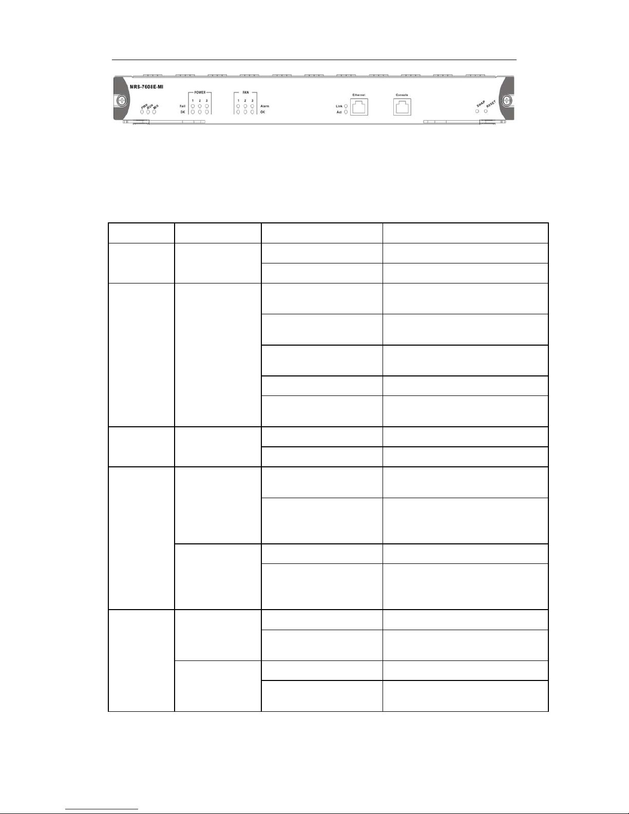
1.4.2.2 MRS-7608E-MI
The MRS-7608E-MI is switching module for the DCRS-7608E. System status control,
switch management, user access control and management, and network maintenances
are performed here. The board can be inserted into M1 or M2 slots of the chassis for
Master-Slave redundancy.
1.4.2.2.1 Front Panel
The MRS-7608E-MI comes with 1 Console port (control console) and 1
10/100Base-Tx Ethernet port (management port).
The Front Panel view is shown below:
DCRS-7600E InstallManual Chapter 1 Product Overview
1-20
Fig 1-8 MRS-7608E-MI Front Panel view
1.4.2.2.2 Front Panel - Indicator
The following table describes the front panel indicators of MRS-7608E-MI:
Table 1-4 MRS-7608E-MI indicators description
LED Panel Symbol Status Description
Power
Indicator
PWR
On (Green) Card powered
Off Card powered off
Operation
indicator
RUN
On (Green, blink at 1
Hz)
Cards operating normally
On (Green, blink at 8
Hz)
System is loading
On (Yellow, blink at 8
Hz)
System is shutting down
On (Red, blink at 8 Hz) Cards malfunction
Off
Cards are powered off and can be
removed
Master-Slav
e indicator
M/S
On (Green) Master
Off Slave
Power
Supply
Module
Status
indicator:
POWER
OK
On (Green)
Power Supply Module operating
normally
Off
Power supply module
malfunctioning or not present (with
Fail off)
Fail
On (Yellow) Power Supply Module malfunction
Off
Power supply module operating
normally or not present (with OK
off)
Fan
Assembly
Status
indicator:
FAN
OK
On (Green) Fan operating normally
Off
Fan malfunctioning or not present
(with Alarm off)
Alarm
On (Yellow) Fan malfunction
Off
Fan operating normally or not
present (with OK off)
1.4.2.2.3 Front Panel – Console Port
DCRS-7600E InstallManual Chapter 1 Product Overview
1-21
The MRS-7608E-MI provides a RJ-45 (receptacle) Console serial port. Users can
connect to hosts via this port to perform system debugging, conf iguration, maintenance,
management and host software loading.
Table 1-5 MRS-7608E-MI Console description
Property Specification
Connector
RJ-45 (receptacle)
Connector type
RS-232
Baud rate
9600bps (default)
Supporting service
Connects to character terminals
Connects to PC serial port and run ning terminal emulator
on PC.
1.4.2.2.4 Front Panel – Management Port
The MRS-7608E-MI provides a RJ-45 (receptacle) Ethernet port. Users can connect
through this management port to hosts for program loading or to connect to remote
devices for remote management (e.g., a managing workstation). Not e: when connecting
to the host, a cross-over cable should be used.
Table 1-6 MRS-7608E-MI management port description
Property Specification
Connector
RJ-45 (Receptacle)
Connector type
10/100Mbps auto sensing
Cat 5 UTP: 300 m
1.4.2.2.5 Front Panel – Reset Button
MRS-7608E-MI provides a RESET button for resetting the board.
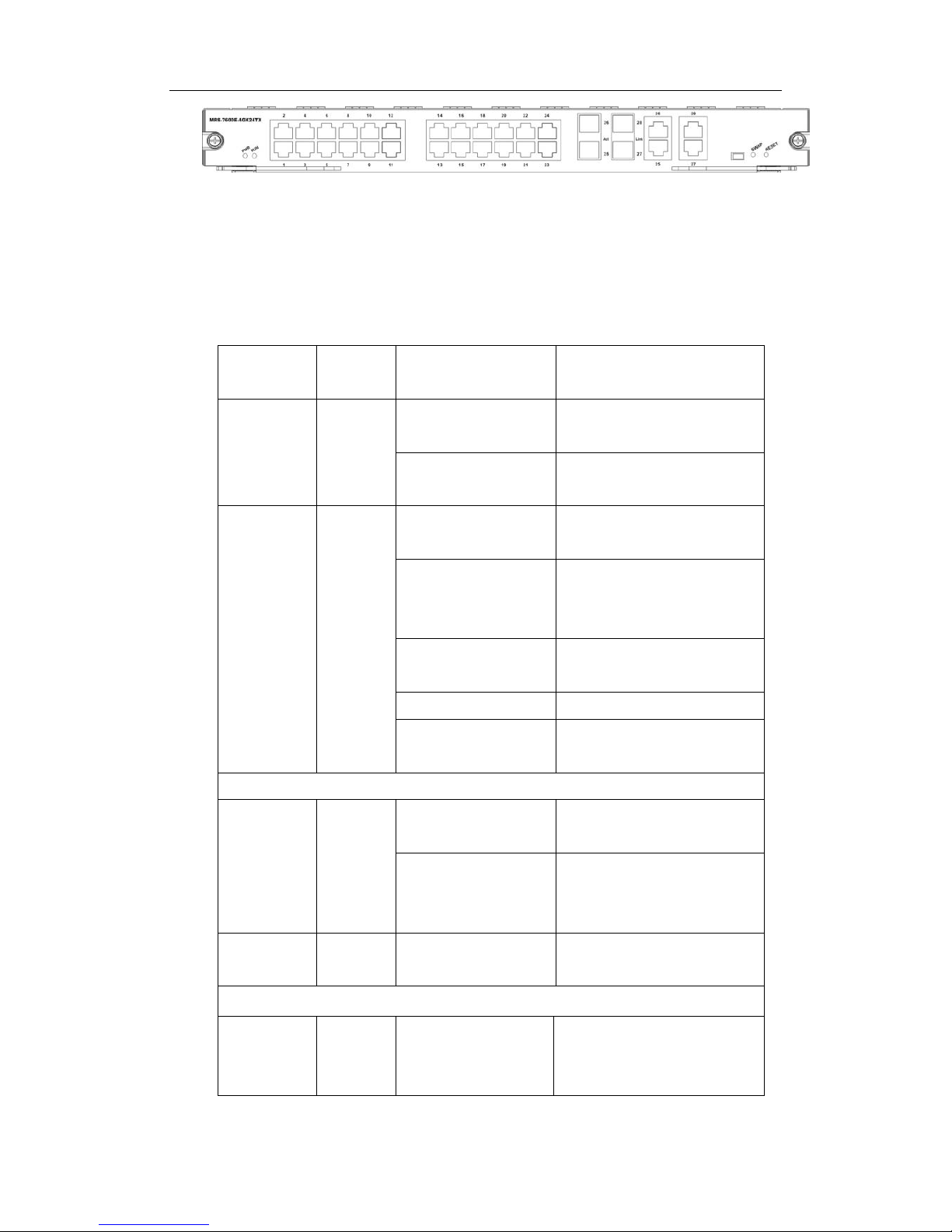
1.4.2.3 MRS-7600E-4GX24TX
MRS-7600E-4GX24TX is the line card exchange model of DCRS-7600E series
exchanges. It implements the layer2 and layer3 wire speed exchange and routing function
of twenty four 10/100M electronic ports and four 1G COMBO (4 10/100/1000M electroni c
interfaces or four 1G optical interfaces).
1.4.2.3.1 Front Panel Diagram
MRS-7600E-4GX24TX provides twenty four 10/100M electronic ports and four 1G
COMBO.
DCRS-7600E InstallManual Chapter 1 Product Overview
1-22
Fig
1-9 MRS-7600E-4GX24TX front panel view
1.4.2.3.2 Front Panel Indicator
The description of front panel indicator of MRS-7600E-4GX24TX is as follows:
Table 1-7 MRS-7600E-4GX24TX indicator description
Indicator
Panel
Sign
Status Meanings
Power
Indicator
PWR
On (Green)
Network Interface Card
power on
Off
Network Interface Card
power off
Running
Indicator
RUN
On (Green 1Hz
flash)
Network Interface Card
running in normal status
On (Green 8Hz
flash)
System
loading (Network
Interface Card Booting after
hot plug in)
On (Yellow 8Hz
flash)
System shutting down
On (Red 8Hz flash)
Running status is in failure
Off Network Interface Card is off
and can be pulled out
SFP Interface indicator
Status
Indicator
Link
On (Green)
SFP transceiver network
connection is normal
Off
There is not network
connection at SFP
transceiver
Transmissio
n Indicator
Act Flashes (Green) Sending or receiving data
100MB electronic port indicator
Status
Indicator
Link On (Green)
100MB electronic port
transceiver network
connection is normal

DCRS-7600E InstallManual Chapter 1 Product Overview
1-23
Off
There is not network
connection at 100MB
electronic port transceiver
Transmissio
n Indicator
Act Flashes (Green) Sending or receiving data
1GB Electronic Port Indicator
Status
Indicator
Link
Flashes (Green)
1GB electronic port
transceiver network
connection is normal
Off
There is not network
connection at 1GB
electronic port transceiver
Transmissio
n Indicator
Act Flashes (Green) Sending or receiving data
1.4.2.3.3 Front Panel Interface Description
MRS-7600E-4GX24TX provides twenty four 10/10 0M and four 1G COMBO.
1.4.2.3.4 Front Panel RESET Button
MRS-7600E-4GX24TX provides a RESET button to reset the panel.
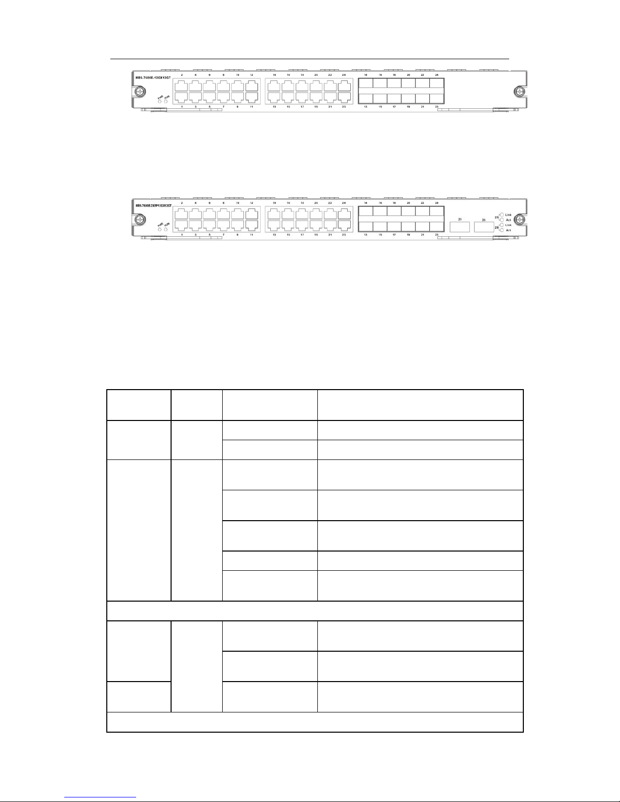
1.4.2.4 MRS-7600E-12GX12GT and
MRS-7600E-2XFP12GX12GT
12-port optical-electronic combo and 12-port electronic interface line card
(MRS-7600E-12GX12GT): to implement the layer 2 and layer3 wire speed exchang e and
routing function of 12-port 1G optical-electronic combo and 12-port 1G electronic interface
and IPv6 wire speed transmission function.
Double 10G and 12-port optical-electronic combo and 12-port electronic interface line
card (MRS-7600E-2XFP12GX12GT): to implement the layer2 and layer3 wire speed
exchange and routing function of 12-port 1G optical-electronic combo, 12-port 1G
electronic and 2-port 10G XFP interface, and IPv6 wire speed transmission function.
1.4.2.4.1 Front Panel Diagram
MRS-7600E-12GX12GT provides twelve 1G SFP ports, twenty four 1G electronic
ports, where the twelve 1G optical ports and the last twelve 1G electronic ports are combo
ports.
DCRS-7600E InstallManual Chapter 1 Product Overview
1-24
Fig 1-10 MRS-7600E-12GX12GT front panel view
MRS-7600E-2XFP12GX12GT provides two 10G XFP ports, twelve 1G optical SFP
ports, twenty four 1G electronic SFP ports, where the twelve 1G optical ports and the last
twelve 1G electronic ports are combo ports.
Fig 1-11 MRS-7600E-2XFP12GX12GT fr ont panel view
1.4.2.4.2 Front Panel Indicator
The description of front panel indicator of MRS-7600E-12GX12GT and
MRS-7600E-2XFP12GX12GT is as follows:
Table 1-8 MRS-7600E-12GX12GT and MRS-7600E-2XFP12GX12GT indicator
description
LED
Indicator
Panel
Sign
Status Meanings
Power
Indicator
PWR
On (Green) Network Interface Card power on
Off Network Interface Card power off
Running
Indicator
RUN
On (Green 1Hz
flash)
Network Interface Card running in normal
status
On (Green 8Hz
flash)
System loading (Network Interface Card
Booting after hot plug in)
On (Yellow 8Hz
flash)
System shutting down
On (Red 8Hz flash) Running status is in failure
Off
Network Interface Card is off and can be
pulled out
RJ-45 Interface indicator
Status
Indicator
Shared
On (Green)
RJ-
45 Interface Network Connection is
normal
Off
There is not network connection at RJ-45
interface
Transmissio
n Indicator
On (Yellow) Sending or receiving data
SFP Interface Indicator
DCRS-7600E InstallManual Chapter 1 Product Overview
1-25
Status
Indicator
“Left
Light”
On (Green)
SFP transceiver network connection is
normal
Off
There is not network connection at SFP
interface
Transmissio
n Indicator
“Right
Light”
Flashes (Green) Sending or receiving data
XFP interface Indicator
Status
Indicator
Link
On (Green)
XFP transceiver network connection is
normal
Off
There is not network connection at XFP
transceiver
Transmissio
n Indicator
Act Flashes (Green) Sending or receiving data
1.4.2.4.3 Front Panel Interface Description
MRS-7600E-12GX12GT and MRS-7600E-2XFP12GX12GT provide twelve SFP 1G
optical fibre transceivers and twenty four RJ-45 1 G electronic port slots.
MRS-7600E-2XFP12GX12GT provides two XFP 10G optical ports.
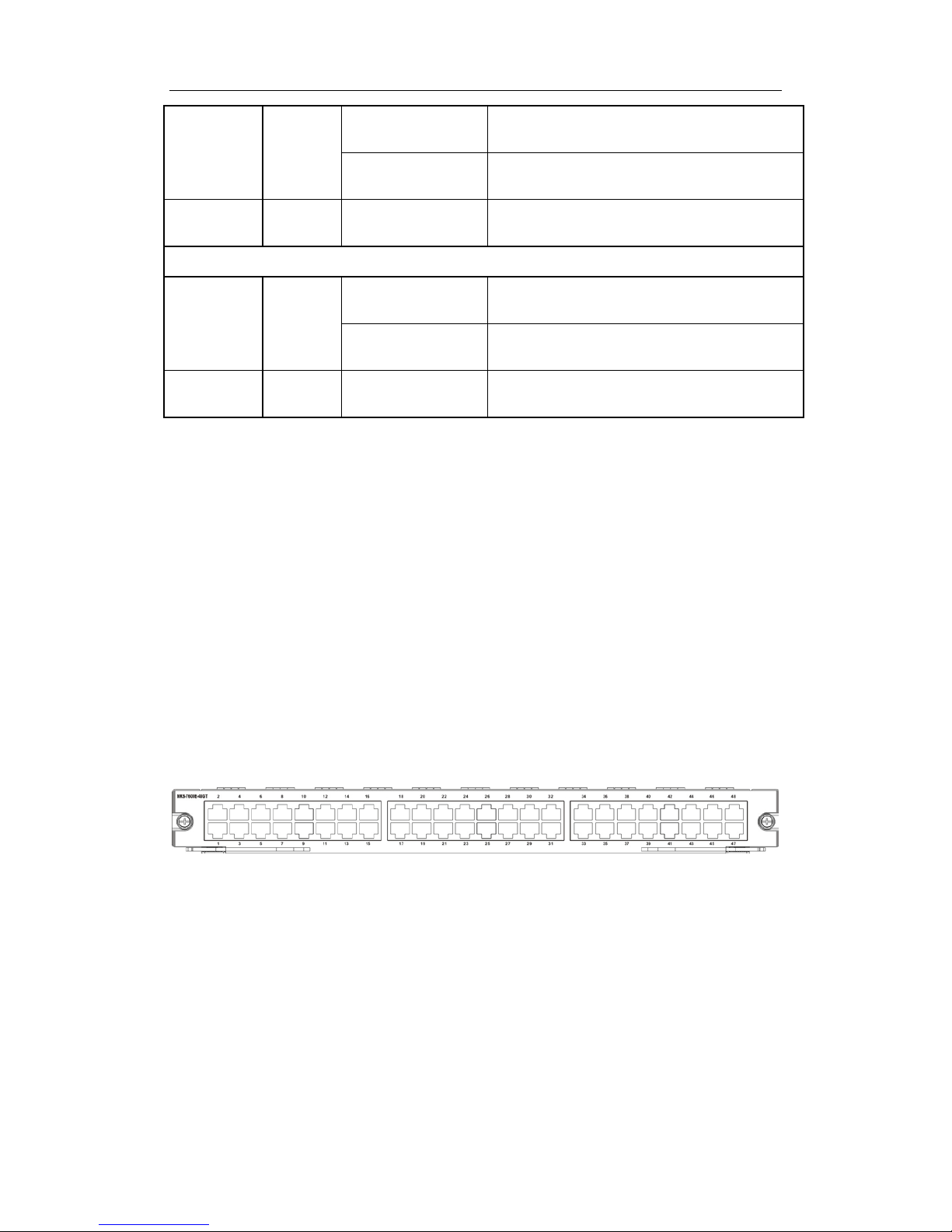
1.4.2.5 MRS-7600E-48GT
48GT electronic interface line card (MRS-7600E-48GT): to implement the layer2 and
layer3 wire speed exchange and routing function of 48GT electroni c interface and IPv6
wire speed transmission function.
1.4.2.5.1 Front Panel Diagram
MRS-7600E-48GT provides 48-Port 10/100/1000M Ethernet electronic ports,
Fig 1-12 MRS-7600E-48GT front panel view
The ports in the above chart are port GE1-GE48 from the bottom-left corner to the
top-right corner. The indicator lamps of ports having odd index number are on the left side
of the port array, while the indicator lamps of ports having even index number are on the
right side. The lamps are green and orange double indicator lamps.
1.4.2.5.2 Front Panel Indicator
The description of front panel indicator of MRS-7600E-48GT as foll ows:
DCRS-7600E InstallManual Chapter 1 Product Overview
1-26
Table 1-9 MRS-7600E-48GT indicator description
LED
Indicator
Panel
Sign
Status Meanings
RJ-45 Interface indicator
Status
Indicator
Shared
On (Green)
RJ-
45 Interface Network Connection is
normal
Off
There is not network connection at RJ-45
interface
Transmissio
n Indicator
On (Yellow) Sending or receiving data
1.4.2.5.3 Front Panel Interface Description
MRS-7600E-48GT provides 48-port 10/100/1000M RJ-45 electronic port.
1.4.2.6 MRS-7604E-M1XFP12GX12GT
The MRS-7604E-M1XFP12GX12GT is switching module for the DCRS-7604E.
System status control, switch management, user acc ess control and management, and
network maintenances are performed here. The board can be inserted into first or second
slots of the chassis for Master-Slave redundancy. 12-port 1G optical-electronic combo,
12-port 1G electronic and 2-port 10G XFP interface, and IPv6 wire speed transmission
function.
1.4.2.6.1 Front Panel Diagram
MRS-7604E-MIXFP12GX12GT provides 2-port 1G optical-electronic combo, 12-port
1G electronic and 1-port 10G XFP interface. It implements 2-layer and 3-layer wire-speed
switching, routing function and IPv6 transmission. The front 12 ports are 1000M electronic
ports and the last 12 ports are combo ports.
Fig 1-13 MRS-7604E-M1XFP12GX12GT front panel view
1.4.2.6.2 Front Panel Indicator
The description of front panel indicator of MRS-7604E-M1XFP12GX12GT as follows:
Table 1-10 MRS-7604E-M1XFP12GX12GT indicator description

DCRS-7600E InstallManual Chapter 1 Product Overview
1-27
LED
Indicator
Panel
Sign
Status Meanings
Power
Indicator
PWR
On (Green) Network Interface Card power on
Off Network Interface Card power off
Master-Slav
e indicator
M/S
On (Green) Master
Off Slave
FAN
indicator
FAN
On(Green) Fan present and operating normally
On(Red)
Fan not present or operating abnormally
Off
Fan not present
Running
Indicator
RUN
On (Green 1Hz
flash)
Network Interface Card running in normal
status
On (Green)
System loading (Network Interface Card
Booting after hot plug in)
Off Network Interface Card running abnormally
RJ-45 Interface indicator
Status
Indicator
On (Green)
RJ-
45 Interface Network Connection is
normal
Off
There is not network connection at RJ-45
interface
On (Orange) Sending or receiving data
SFP Interface Indicator
Status
Indicator
“Left
Light”
On (Green)
SFP transceiver network connection is
normal
Off
There is not network connection at SFP
interface
Transmissio
n Indicator
“Right
Light”
Flashes (Green) Sending or receiving data
XFP interface Indicator
Status
Indicator
Link
On (Green)
XFP transceiver network connection is
normal
Off
There is not network connection at XFP
transceiver
Transmissio
n Indicator
Act Flashes (Green) Sending or receiving data
1.4.2.6.3 Front Panel Interface Description
MRS-7604E-M1XFP12GX12GT provides 12-port 1G optical-electronic combo,
24-port 1G electronic and 1-port 10G XFP interface.

DCRS-7600E InstallManual Chapter 1 Product Overview
1-28
1.4.2.7 MRS-7600E-4XFP
MRS-7600E-4XFP implements 2-layer and 3-layer wire-spee d switching and routing
function of 4 10,000Mbps XFP interfaces and IPv6 wire-speed transmission.
1.4.2.7.1 Front Panel Diagram
The following is the sketch map of its front panel:
Fig 1-14 the Sketch Map of the Front Panel of MRS-7600E-4XFP
1.4.2.7.2 Front Panel Indicator
The following is the instruction of the indicator lamps on the front panel of
MRS-7600E-4XFP.
Table 1-11 the Instruction of Indicator Lamps of MRS-7600E-4XFP
LED
Indicator
Panel
Sign
State Explanation
Power
Indicator
Lamp
PWR
On(green) The boardcard is power-on
Off The boardcard is power-off
Run
Operating
Indicator
RUN
On(green,
glittering at the
frequency of 1 HZ)
The boardcard is operating normally
On(green,
glittering at the
frequency of 8 HZ)
The system is booting(Booting
after the
boardcard is hot-plugged in)
Off The boardcard is operating abnormally
XFP Interface Indicator Lamps
State
Indicator
Lamp
Link
On(green)
The network connection of XFP Transceiver
is normal.
Off
There is no network connection o
n XFP
Transceiver
Transmissio
n Indicator
Lamp
Act On(green) Receiving or sending data.
1.4.2.7.3 Front Panel Interfaces Description

DCRS-7600E InstallManual Chapter 1 Product Overview
1-29
MRS-7600E-4XFP provides 4 10,000Mbps XFP electric interfaces.
1.4.2.8 MRS-7600E-48GB
48-port 1000Mbps optical line card (MRS-7600E-48GB): Implements 2-layer and
3-layer wire-speed switching and routing function of 48 1000Mbps optical interfaces, and
IPv6 wire-speed transmission.
1.4.2.8.1 Front Panel Diagram
MRS-7600E-48GB provides 48 1000Mbps optical interfac es.
The following is the sketch map of its front panel:
Fig 1-15 the Sketch Map of the Front Panel of MRS-7600E-48GB
The ports in the above chart are port GB1-GB48 from the bottom-left corner to the
top-right corner. The indicator lamps of ports having odd index number are on the left side
of the port array, while the indicator lamps of ports having even index number are on the
right side. The lamps are green indicator lamps.
1.4.2.8.2 Front Panel Indicator
The following is the instruction of the indicator lamps on the front panel of
MRS-7600E-48GB.
Table 1-12 the Instruction of Indicator Lamps of MRS-7600E-48GB
LED
Indicator
Panel
Sign
State Explanation
SFP Interface Indicator Lamps
State
Indicator
Lamp
On(green)
The network connection of SFP interface is
normal.
Off
There is no netw
ork connection on SFP
interface
Transmissio
n Indicator
Lamp
On(green) SFP is receiving or sending data.
1.4.2.8.3 Front Panel Interface Description
MRS-7600E-48GB provides 48 SFP 1000Mbps optical transceiver interfaces.

DCRS-7600E InstallManual Chapter 1 Product Overview
1-30
1.4.2.9 MRS-7604E-M44GT
The MRS-7604E-M44GT is switching module for the DCRS-7604E switch. System
status control, switch management, user access control and management, and network
maintenances are performed here. The board can be inserted into firs t or second slots of
the chassis for Master-Slave redundancy, supports IPv6 wire-speed transmission. It has
44 1000Mbps electronic interfaces at the same time.
1.4.2.9.1 Front Panel Diagram
MRS-7604E-M44GT implements 2-layer and 3-layer wire-speed switching and
routing function of 44 1000Mbps electronic interfaces and IPv6 transmission.
The following is the sketch map of its front panel:
Fig 1-16 the Sketch Map of the Front Panel of MRS-7604E-M44GT
1.4.2.9.2 Front Panel Indicator
The following is the instruction of the indicator lamps on the front panel of
MRS-7604E-M44GT.
Table1-13 MRS-7604E-M44GT indicator description
LED
Panel
Symbol
Status Description
Power
Indicaor
PWR
On(Green)
Card Powered
Off
Card Powered off
Master-Slave
Indicator
M/S
On(Green)
Master
Off
Slave
Fan
Indicator
FAN
On(Green)
Operating normally
Off
Operating abnormally
Operation
Indicator
RUN
On(Green, blink at 1
Hz)
Cards operating normally
On(Green, blink at 8
Hz)
System is loading (Booting
after the
boardcard is hot-plugged in)
Off
Operating malfunctioning
RJ-45 Interface Indicator
Port
On(Green)
The network connection of RJ-45

DCRS-7600E InstallManual Chapter 1 Product Overview
1-31
indicator
interface is normal
Off
There is no network connection on
RJ-45 interface
On(Orange)
Receiving or sending data
1.4.2.9.3 Front Panel Interface Description
MRS-7604E-M44GT provides 44-port 10/100/1000M RJ-45 elec tronic port.
1.4.2.10 MRS-7604E-M1XFP12GX12GB
The MRS-7604E-M1XFP12GX12GB is switching module for the DCRS-7604E.
System status control, switch management, user acc ess control and management, and
network maintenances are performed here. The board can be inserted into first or second
slots of the chassis for Master-Slave redundancy. MRS-7604E-M1XFP12GX12GB
supports 2-layer and 3-layer wire-speed switchi ng and routing function of 12 1000Mbps
optical-electronic combos, 12 1000Mbps opticals and 1 10,000Mbps XFP interfaces, IPv6
wire-speed transmission.
1.4.2.10.1 Front Panel Diagram
MRS-7604E-M1XFP12GX12GB provides 12-port 1G optical-electronic combo,
12-port 1G optical and 1-port 10G XFP interface. 12-port 1G optical-electronic are combo
at the front, 12-port are 1G optical interface at the back.
The following is the sketch map of its front panel:
Fig 1-17 the Sketch Map of the Front Panel of MRS-7604E-M1XFP12GX12GB
1.4.2.10.2 Front Panel Indicator
The following is the instruction of the indicator lamps on the front panel of
MRS-7604E-M1XFP12GX12GB.
Table1-14 MRS-7604E-M1XFP12GX12GB indicator descripti on
LED
Panel
Symbol
Status Description
Power
Indicaor
PWR
On(Green)
Card Powered
Off
Card Powered off
Master-Slave
Indicator
M/S
On(Green)
Master
Off
Slave

DCRS-7600E InstallManual Chapter 1 Product Overview
1-32
Fan
Indicator
FAN
On(Green)
Fan operating normally
Off
Fan not present or operating
abnormally
Operation
Indicator
RUN
On(Green, blink at 1
Hz)
Cards operating normally
On(Green, blink at 8
Hz)
System is loading (Booting
after the
boardcard is hot-plugged in)
Off
Operating malfunctioning
RJ-45 Interface Indicator
Port
Indicator
On(Green)
The network connection of RJ-45
interface is normal
Off
There is no network connection on
RJ-45 interface
On(Orange)
Receiving or sending data
SFP Interface Indicator
Status
Indicator
“Left
Light”
On (Green)
SFP transceiver network
connection is normal
Off
There is not network connection at
SFP interface
Transmission
Indicator
“Right
Light”
On (Green) Sending or receiving data
XFP Interface Indicator
Status
Indicator
Link
On (Green)
XFP transceiver network
connection is normal
Off
There is not network connection at
XFP transceiver
Transmission
Indicator
Act On (Green) Sending or receiving data
1.4.2.10.3 Front Panel Interface Description
MRS-7604E-M1XFP12GX12GB provides 24 SFP 1000Mbps optical fibre
transceivers, 12 RJ-45 1000Mbps electronic port slots and 1 XFP 10,000Mbps electronic
port.
1.4.2.11 MRS-7600E-12GX12GB and
MRS-7600E-2XFP12GX12GB
The MRS-7600E-12GX12GB is switching module for the 76 series switch and
implements 2-layer and 3-layer wire-speed switching and routing function of 12 1000Mbps

DCRS-7600E InstallManual Chapter 1 Product Overview
1-33
optical-electronic combo, 12 1000Mbps optical interfaces, IPv6 wire-speed transmission.
The MRS-7600E-2XFP12GX12GB is switching module for the 76 series swi tch and
implements 2-layer and 3-layer wire-speed switching and routing function of 12 1000Mbps
optical-electronic combo, 12 1000Mbps optical and 2 10,000Mbps XFP interfaces, IPv6
wire-speed transmission.
1.4.2.11.1 Front Panel Diagram
MRS-7600E-12GX12GB provides 12 1000Mbps optical-electronic combo and 12
1000Mbps optic al interfaces. 12 1000Mbps electronic ports are combo ports at the front,
12 ports are 1000Mbps optical port at the back.
The following is the sketch map of its front panel:
Fig 1-18 the Sketch Map of the Front Panel of MRS-7600E-12GX12GB
The MRS-7600E-2XFP12GX12GB provides 12 1000Mbps optical-electronic combo,
12 1000Mbps optical interfaces and 2 10,000Mbps XFP interfaces. 12 1000Mbps
electronic ports are combo ports at the front, 12 ports are 1000Mbps optical ports at the
back.
The following is the sketch map of its front panel:
Fig 1-19 the Sketch Map of the Front Panel of MRS-7600E-2XFP12GX12GB
1.4.2.11.2 Front Panel Indicator
The following is the instruction of the indicator lamps on the front panel of
MRS-7600E-12GX12GB and MRS-7600E-2XFP12GX12GB.
Table1-15 MRS-7600E-12GX12GB and MRS-7600E-2XFP12GX12GB indicator
description
LED
Panel
Symbol
Status Description
Power
Indicaor
PWR
On(Green)
Card Powered
Off
Card Powered off
Operation
Indicator
RUN
On(Green, blink at 1
Hz)
Cards operating normally
On(Green, blink at 8
Hz)
System is loading (Booting
after the
boardcard is hot-plugged in)

DCRS-7600E InstallManual Chapter 1 Product Overview
1-34
Off
Operating malfunctioning
RJ-45 Interface Indicator
Port
Indicator
On(Green)
The network connection of RJ-45
interface is normal
Off
There is no network connection on
RJ-45 interface
On(Orange)
Receiving or sending data
SFP Interface Indicator
Status
Indicator
“Left
Light”
On (Green)
SFP transceiver network
connection is normal
Off
There is not network connection at
SFP interface
Transmission
Indicator
“Right
Light”
On (Green) Sending or receiving data
XFP Interface Indicator
Status
Indicator
Link
On (Green)
XFP transceiver network
connection is normal
Off
There is not network connection at
XFP transceiver
Transmission
Indicator
Act On (Green) Sending or receiving data
1.4.2.11.3 Front Panel Interface Description
MRS-7600E-12GX12GB and MRS-7600E-2XFP12GX12GB provides 24 SFP
1000Mbps optical fibre transceivers, 12 RJ-45 1000Mbps electronic port slots.
MRS-7600E-2XFP12GX12GT provides 2 XFP 10,000Mbps optical ports.
1.4.2.12 MRS-7608E-M2
The MRS-7608E-M2 is main switching module for the DCRS -7608E, the important
functions such as system status control, route management, user access control and
management, network maintenances are performed here. The board can b e inserted i nto
M1 or M2 slots of the chassis switch and support Master-Slave redundancy.
1.4.2.12.1 Front Panel Diagram
The MRS-7608E-M2 provide 1 Console port (control platform), and 1
10/100/1000Base-Tx Ethernet port (management port).
The Front Panel is shown as below:

DCRS-7600E InstallManual Chapter 1 Product Overview
1-35
Fig 1-20 MRS-7608E-M2 Front Panel
1.4.2.12.2 Front Panel Indicator
The following table describes the front panel indicators of MRS-7608E-M2:
Table1-16 MRS-7608E-M2 indicator description
LED
Panel
Symbol
Status Description
Power
Indicaor
PWR
On(Green)
Card Powered
Off
Card Powered off
Operation
Indicator
RUN
On(Green, blink at 1
Hz)
Cards operating normally
On(Green, blink at 8
Hz)
System is loading when the card is
hot plugged
On(Yellow, blink at 8
Hz)
System is shutting down
On(
Red, blink at 8
Hz)
Cards malfunction
Off
Cards are powered off and can be
removed
Master-Slave
indicator
M/S
On(Green)
Master
Off
Slave
Power
Supply
Module
Status
indicator:
POWER
OK
On(Green)
Power Supply Module operating
normally
Off
Power supply module
malfunctioning or not present (with
Fail off)
Fail
On(Yellow)
Power Supply Module malfunction
Off
Power supply module operating
normally or not present (with OK
off)
Fan Assembly
Status
indicator
FAN
OK
On(Green)
Fan operating normally
Off
Fan malfunctioning or not present
(with Alarm off)
Alarm
On(Yellow)
Fan malfunction

DCRS-7600E InstallManual Chapter 1 Product Overview
1-36
Off
Fan operating normally or not
present (with OK off)
1.4.2.12.3 Front Panel Console
The MRS-7608E-M2 provides a RJ-45 (receptacle) Console s erial port. Users can
connect to background terminal computers via this port to perform system debugging,
configuration, maintenance, management and hos t software loading.
Table1-17MRS-7608E-M2 Console Port Description
Property Specification
Connector
RJ-45(receptacle)
Connector type
RS-232
Baud rate
9600bps(default)
Supporting Service
Connects to character termi nals
Connects to PC serial port and runni ng terminal
emulator on PC
1.4.2.12.4 Front Panel Management Port
The MRS-7608E-M2 provides a RJ-45 (rec eptacle) Et hernet port . Us ers can c onnec t
through this management port to backgrou nd t ermi nal c omput er for program loading or to
connect to remote devices for remote management (e.g., a managing workstation). Note:
when connecting to the host, a cross-over cable should be used.
Table1-18 MRS-7608E-M2 Management Port description
Property Specification
Connector
RJ-45(receptacle)
Connector type
10/100/1000Mbps adapting
Cat 5(UTP): 300m
1.4.2.13 MRS-7608E-M3
The MRS-7608E-M3 is main switc hing module for the DCRS-7608E, the important
functions such as system status control, route management, user access control and
management, network maintenances are performed here. The board can b e inserted into
M1 or M2 slots of the chassis switch and support Master-Slave redundancy.
1.4.2.13.1 Front Panel Diagram

DCRS-7600E InstallManual Chapter 1 Product Overview
1-37
The MRS-7608E-M3 provide 1 Console port (control platform), and 1
10/100/1000Base-Tx Ethernet port (management port).
The Front Panel is shown as below:
Fig 1-21 MRS-7608E-M3 Front Panel
1.4.2.13.2 Front Panel Indicator
The following table describes the front panel indicators of MRS-7608E-M3:
Table1-19 MRS-7608E-M3 indicator description
LED
Panel
Symbol
Status Description
Power
Indicaor
PWR
On(Green)
Card Powered
Off
Card Powered off
Operation
Indicator
RUN
On(Green, blink at 1
Hz)
Cards operating normally
On(Green, blink at 8
Hz)
System is loading when the card is
hot plugged
On(Yellow, blink at 8
Hz)
System is shutting down
On(
Red, blink at 8
Hz)
Cards malfunction
Off
Cards are powered off and can be
removed
Master-Slave
indicator
M/S
On(Green)
Master
Off
Slave
Power
Supply
Module
Status
indicator:
POWER
OK
On(Green)
Power Supply Module operating
normally
Off
Power supply module
malfunctioning or not present (with
Fail off)
Fail
On(Yellow)
Power Supply Module malfunction
Off
Power supply module operating
normally or not present (with OK
off)
Fan Assembly
Status
OK
On(Green)
Fan operating normally
Off
Fan malfunctioning or not present

DCRS-7600E InstallManual Chapter 1 Product Overview
1-38
indicator
FAN
(with Alarm off)
Alarm
On(Yellow)
Fan malfunction
Off
Fan operating normally or not
present (with OK off)
1.4.2.13.3 Front Panel Console
The MRS-7608E-M3 pro vides a RJ-45 (receptacle) Console serial port. Users can
connect to background terminal computers via this port to perform system debugging,
configuration, maintenance, management and hos t software loading.
Table1-20MRS-7608E-M3 Console Port Description
Property Specification
Connector
RJ-45(receptacle)
Connector type
RS-232
Baud rate
9600bps(default)
Supporting Service
Connects to character termi nals
Connects to PC serial port and runni ng terminal
emulator on PC
1.4.2.13.4 Front Panel Management Port
The MRS-7608E-M3 provides a RJ-45 (receptacle) E thernet port . Users can c onnec t
through this management port to backgrou nd t ermi nal c omput er for program loading or to
connect to remote devices for remote management (e.g., a managing workstation). Note:
when connecting to the host, a cross-over cable should be used.
Table1-21 MRS-7608E-M3 Management Port description
Property Specification
Connector
RJ-45(receptacle)
Connector type
10/100/1000Mbps adapting
Cat 5(UTP): 300m
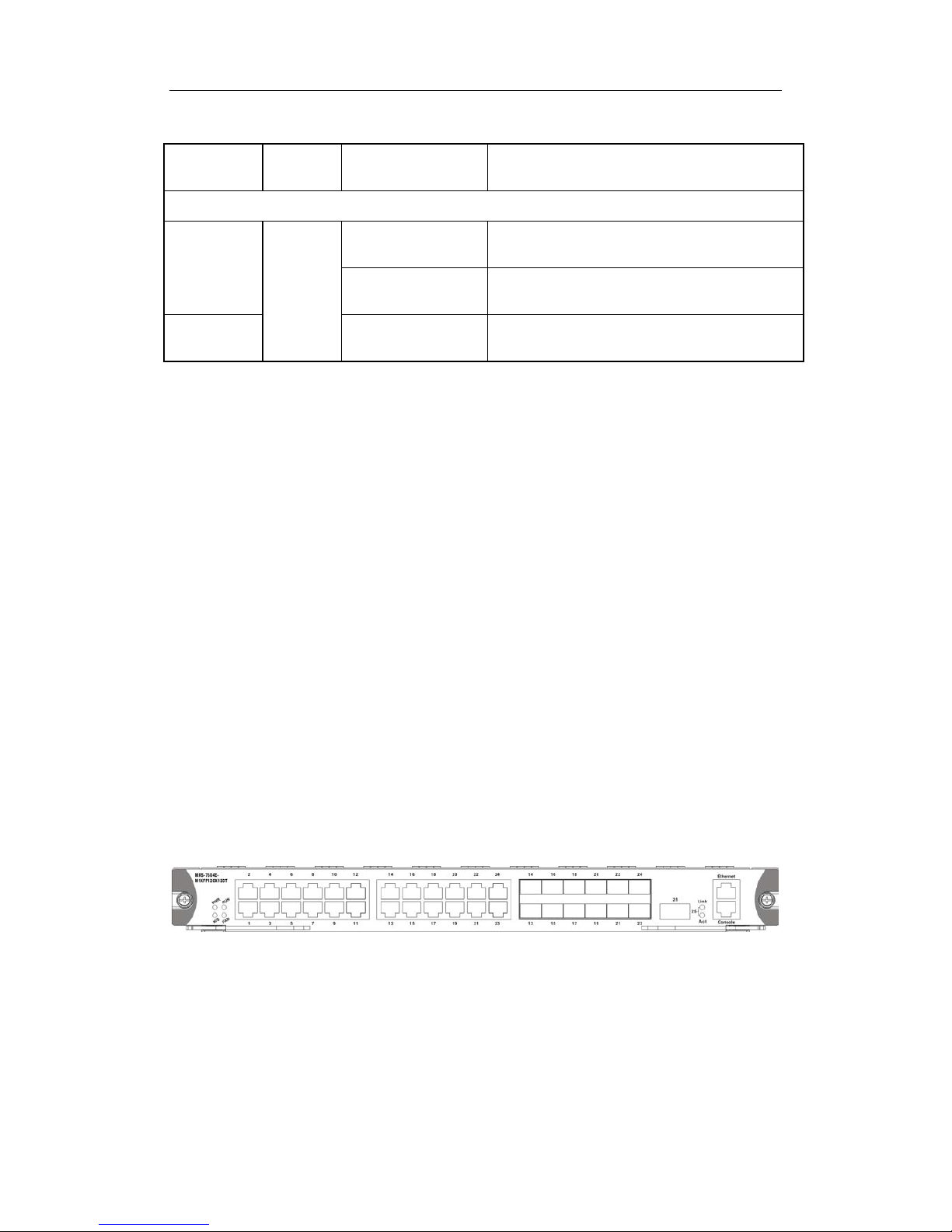
1.4.2.14 MRS-7600E-24GB12GT and
MRS-7600E-2XFP24GB12GT
The MRS-7600E-24GB12GT is switching module for the 7600E series switch, which
supports MPLS VPN function and implements 2-layer and 3-layer wire-speed s witching

DCRS-7600E InstallManual Chapter 1 Product Overview
1-39
and routing function of 12 1000Mbps electronic interfaces, 24 1000Mbps optical
interfaces, IPv6 wire-speed transmission.
The MRS-7600E-2XFP24GB12GT is switching module for the 7600E series switch,
which supports MPLS VPN function and implements 2-layer and 3-layer wire-speed
switching and routing function of 12 1000Mbps electronic interfaces, 12 1000Mbps optical
and 2 10,000Mbps XFP interfaces, IPv6 wire-speed transmission.
1.4.2.14.1 Front Panel
The MRS-7600E-24GB12GT provides 12 1000Mbps electronic interfaces and 24
1000Mbps optical interfaces.
The Front Panel view is shown below:
Fig 1-22 MRS-7600E-24GB12GT Front Panel View
MRS-7600E-2XFP24GB12GT provides 12 1000Mbps electronic interfaces, 24
1000Mbps optical and 2 10,000Mbps XFP interfaces.
The Front Panel view is shown below:
Fig 1-23 MRS-7600E-24GB12GT Front Panel View
1.4.2.14.2 Front Panel - Indicator
The following is the instruction of the indicator lamps on the front panel of
MRS-7600E-24GB12GT and MRS-7600E-2XFP24GB12GT.
Table1-22 MRS-7600E-24GB12GT and MRS-7600E-2XFP24GB12GT indicator
description
LED
Panel
Symbol
Status Description
Power
Indicaor
PWR
On(Green) Card Powered
Off
Card Powered off
Operation
Indicator
RUN
On(Green, blink at
1 Hz)
Cards operating normally
On(Green, blink at
8 Hz)
System is loading (
Booting after the
boardcard is hot-plugged in)

DCRS-7600E InstallManual Chapter 1 Product Overview
1-40
Off
Operating malfunctioning
RJ-45 Interface Indicator
Port
Indicator
On(Green)
The network connection of RJ-45 interface
is normal
Off
There is no network connection on RJ-45
interface
On(Orange)
Receiving or sending data
SFP Interface Indicator
Status
Indicator
“Left
Light”
On (Green)
SFP transceiver network connection is
normal
Off
There is not network connection at SFP
interface
Transmissio
n Indicator
“Right
Light”
On (Green) Sending or receiving data
XFP Interface Indicator
Status
Indicator
Link
On (Green)
XFP transceiver network connection is
normal
Off
There is not network connection at XFP
transceiver
Transmissio
n Indicator
Act On (Green) Sending or receiving data
1.4.2.14.3 Front Panel Interface Description
MRS-7600E-24GB12GT provides 12 1000Mbps electronic interfaces and 24
1000Mbps optical interfaces.
MRS-7600E-2XFP24GB12GT provides 12 1000Mbps electronic interfaces, 24
1000Mbps optical and 2 10,000Mbps XFP interfaces.
1.4.2.15 MRS-7600E-12GX12GT (R2) and
MRS-7600E-2XFP12GX12GT (R2)
12-port optical-electronic combo and 12-port electronic interface line card
(MRS-7600E-12GX12GT(R2)): The switching module for the DCRS-7604E(R2), to
implement the layer2 and layer3 wire speed exchange and r outing function of 12-port 1 G
optical-electronic combo and 12-port 1G electronic interface and IPv6 wire speed
transmission function.

DCRS-7600E InstallManual Chapter 1 Product Overview
1-41
Double 10G and 12-port optical-electronic combo and 12-port electronic interface line
card (MRS-7600E-2XFP12GX12GT(R2)): The switching module for the
DCRS-7604E(R2), implement the layer2 and layer3 wire speed exchange and routing
function of 12-port 1G optical-electronic combo, 12-port 1G electronic and 2-port 10G XFP
interface, and IPv6 wire speed transmissi on function.
1.4.2.15.1 Front Panel Diagram
MRS-7600E-12GX12GT (R2) provides twelve 1G optical combo ports, twelve 1G
electronic ports, where the twelve 1G optical ports and the last twelve 1G ele ctronic ports
are combo ports.
Fig 1-24 MRS-7600E-12GX12GT(R2) front panel view
MRS-7600E-2XFP12GX12GT (R2) provides two 10G XFP ports, twelve 1G optical
SFP ports, twelve 1G electronic SFP ports, where the twelve 1G optical ports and the last
twelve 1G electronic ports are combo ports.
Fig 1-25 MRS-7600E-2XFP12GX12GT(R2) front panel view
1.4.2.15.2 Front Panel Indicator
The description of front panel indicator of MRS-7600E-12GX12GT (R2) and
MRS-7600E-2XFP12GX12GT (R2) is as follows:
Table 1-23 MRS-7600E-12GX12GT (R2) and MRS-7600E-2XFP12GX12GT (R2)
indicator description
LED
Indicator
Panel
Sign
Status Meanings
Power
Indicator
PWR
On (Green) Network Interface Card power on
Off Network Interface Card power off
Running
Indicator
RUN
On (Green 1Hz
flash)
Network Interface Card running in normal
status
On (Green 8Hz
flash)
System loading (Network Interface Card
Booting after hot plug in)
Off Running status is in failure

DCRS-7600E InstallManual Chapter 1 Product Overview
1-42
RJ-45 Interface indicator
Interface
Indicator
On (Green)
RJ-
45 Interface Network Connection is
normal
Off
There is not network connection at RJ-45
interface
On (Orange)
Sending or receiving data
SFP Interface Indicator
Status
Indicator
“Left
Light”
On (Green)
SFP tran
sceiver network connection is
normal
Off
There is not network connection at SFP
interface
Transmissio
n Indicator
“Right
Light”
On (Green) Sending or receiving data
XFP interface Indicator
Status
Indicator
Link
On (Green)
XFP transceiver network conn
ection is
normal
Off
There is not network connection at XFP
transceiver
Transmissio
n Indicator
Act On (Green) Sending or receiving data
1.4.2.15.3 Front Panel Interface Description
MRS-7600E-12GX12GT (R2) and MRS-7600E-2XFP12GX12GT (R2) provide 24
SFP 1G optical fibre transceivers and 12 RJ-45 1G electronic port slots.
MRS-7600E-2XFP12GX12GT (R2) provides two XFP 10G optical ports.
1.4.2.16 MRS-7600E-48GB (R2)
48-port 1000Mbps optical line card (MRS-7600E-48GB (R2)): The swit ching module
for the DCRS-7604E (R2), implement 2-layer and 3-layer wire-speed switching and
routing function of 48 1000Mbps optical interfaces, and IPv6 wi re-speed transmission.
1.4.2.16.1 Front Panel Diagram
MRS-7600E-48GB (R2) provides 48 1000Mbps optical interfac es.
The following is the sketch map of its front panel:

DCRS-7600E InstallManual Chapter 1 Product Overview
1-43
Fig 1-26 the Sketch Map of the Front Panel of MRS-7600E-48GB(R2)
The ports in the above chart are port GB1-GB48 from the bottom-left corner to the
top-right corner. The indicator lamps of ports having odd index number are on the left side
of the port array, while the indicator lamps of ports having even index number are on the
right side. The lamps are green indicator lamps.
1.4.2.16.2 Front Panel Indicator
The following is the instruction of the indicator lamps on the front panel of
MRS-7600E-48GB (R2).
Table 1-24 the Instruction of Indicator Lamps of MRS-7600E-48GB(R2)
LED
Indicator
Panel
Sign
State Explanation
SFP Interface Indicator Lamps
State
Indicator
Lamp
On(green)
The network connection of SFP interface is
normal.
Off
There is no
network connection on SFP
interface
Transmissio
n Indicator
Lamp
On(green) SFP is receiving or sending data.
1.4.2.16.3 Front Panel Interface Description
MRS-7600E-48GB (R2) provides 48 SFP 1000Mbps optical transceiver interfaces.
1.4.2.17 MRS-7604E-M1XFP12GX12GT (R2)
The MRS-7604E-M1XFP12GX12GT (R2) is swit ching module for the DCRS-7604E
(R2). System status control, switch management, user access control and management,
and network maintenances are performed he re. The board can be inserted into first or
second slots of the chassis for Master-Slave redundancy. 12-port 1G optical-electronic
combo, 12-port 1G electronic and 2-port 10G XFP interface, and IPv6 wire speed
transmission function.
1.4.2.17.1 Front Panel Diagram
MRS-7604E-MIXFP12GX12GT (R2) provides 12-port 1G optical-electronic combo,
12-port 1G electronic and 1-port 10G XFP interface.

DCRS-7600E InstallManual Chapter 1 Product Overview
1-44
Fig 1-27 MRS-7604E-M1XFP12GX12GT(R2) front panel view
1.4.2.17.2 Front Panel Indicator
The description of front panel indicator of MRS-7604E-M1XFP12GX12GT (R2) as
follows:
Table 1-25 MRS-7604E-M1XFP12GX12GT (R2) indicator description
LED
Indicator
Panel
Sign
Status Meanings
Power
Indicator
PWR
On (Green) Network Interface Card power on
Off Network Interface Card power off
Master-Slav
e indicator
M/S
On(Green)
Master
Off Slave
Fan
Indicator
FAN
On(Green)
Fan operating normally
On(Red)
Fan operating abnormally
Off
Fan not present
Running
Indicator
RUN
On (Green 1Hz
flash)
Network Interface Card running in normal
status
On (Green)
System loading (Network Interface Card
Booting after hot plug in)
Off Running status is in failure
RJ-45 Interface indicator
Status
Indicator
Shared
On (Green)
RJ-
45 Interface Network Connection is
normal
Off
There is not network connection at RJ-45
interface
Transmissio
n Indicator
On (Yellow) Sending or receiving data
SFP Interface Indicator
Status
Indicator
“Left
Light”
On (Green)
SFP transceiver network connection is
normal
Off
There is not network connection at SFP
interface
Transmissio
n Indicator
“Right
Light”
Flashes (Green) Sending or receiving data

DCRS-7600E InstallManual Chapter 1 Product Overview
1-45
XFP interface Indicator
Status
Indicator
Link
On (Green)
XFP transceiver network connection is
normal
Off
There is not network connection at XFP
transceiver
Transmissio
n Indicator
Act Flashes (Green) Sending or receiving data
1.4.2.17.3 Front Panel Interface Description
MRS-7604E-M1XFP12GX12GT (R2) provides 12-port 1G optical-electronic combo,
12-port 1G electronic and 2-port 10G XFP interface.
1.4.2.18 MRS-7608E-MI (R2)
The MRS-7608E-MI (R2) is switching module for the DCRS-7608E(R2). System
status control, switch management, user access control and management, and network
maintenances are performed here. The board can be ins erted into M1 or M2 slots of the
chassis for Master-Slave redundancy.
1.4.2.18.1 Front Panel
The MRS-7608E-MI (R2) comes with 1 Console port (control console), 1
10/100Base-Tx Ethernet port (management port) and 1 CF card port.
The Front Panel view is shown below:
Fig 1-28 MRS-7608E-MI(R2) Front Panel view
1.4.2.18.2 Front Panel - Indicator
The following table describes the front panel indicators of MRS-7608E-MI (R2):
Table 1-26 MRS-7608E-MI (R2) indicators description
LED Panel Symbol Status Description
Power
Indicator
PWR
On (Green) Card powered
Off Card powered off
Operation
indicator
RUN
On (Green, blink at 1
Hz)
Cards operating normally

DCRS-7600E InstallManual Chapter 1 Product Overview
1-46
On (Green, blink at 8
Hz)
System is loading
Off Cards malfunction
Master-Slav
e indicator
M/S
On (Green) Master
Off Slave
Power
Supply
Module
Status
indicator:
POWER
POWER _OK
On (Green)
Power Supply Module operating
normally
Off
Power supply module
malfunctioning or not present
POWER_Fail
On (Yellow) Power Supply Module alarm
Off
Power supply module not alarm or
not present
Fan
Assembly
Status
indicator:
FAN
FAN_OK
On (Green) Fan operating normally
Off Fan malfunctioning or not present
FAN_ALARM
On (Yellow) Fan alarm
Off
Fan operating not alarm or not
present
Ethernet
manageme
nt port
indicator
ACT
On (Green)
Ethernet port Sending or receiving
data
Off
Ethernet port Sending or receiving
no data
LINK
On (Green) Ethernet port link successfully
Off Ethernet port link unsuccessfully
CF card
status
indicator
CF-STATUS
On (Green)
CF card is in position
and can
work
Off CF card not present
1.4.2.18.3 Front Panel – Console Port
The MRS-7608E-MI (R2) provides a RJ-45 (receptacle) Cons ole serial port. Users
can connect to hosts via this port to perform system debugging, configuration,
maintenance, management and host software loading.
Table 1-27 MRS-7608E-MI(R2) Console description
Property Specification
Connector
RJ-45 (receptacle)
Connector type
RS-232
Baud rate
9600bps (default)

DCRS-7600E InstallManual Chapter 1 Product Overview
1-47
Supporting service
Connects to character terminals
Connects to PC serial port and run ning terminal emulator
on PC.
1.4.2.18.4 Front Panel – Management Port
The MRS-7608E-MI (R2) provides a RJ-45 (receptacle) Ethernet port. Users can
connect through this management port to hosts for program loading or to connect to
remote devices for remote management (e.g., a managing workstation). Note: when
connecting to the host, a cross-over cable should be used.
Table 1-28 MRS-7608E-MI (R2) management port descript ion
Property
Specification
Connector
RJ-45 (Receptacle)
Connector type
10/100Mbps auto sensing
Cat 5 UTP: 100 m
1.4.2.18.5 Front Panel – CF Card Interface
MRS-7608E-MI (R2) provides a standard CF card slot, and supports hot-swapping.
CF card content supports 256MB/512MB/1GB, it can be save editi on, configuration files
and so on, so as to conveniency switch software update. Notice: It is suggested to ues
DCN CF card, it is not assure the compatibility with other CF card.
1.4.3 Interface description
DCRS-7600E series provide 1000Mbps SFP electric interfaces, RJ-45 (receptacle)
Console serial ports and 10,000Mbps XFP electric interfaces.
Interface description as follow:
Table 1-29 DCRS-7600E series interface descript i on
Interface Format Specs
RJ-45 port
10/100/1000Mbps self-adapting
MDI/MDI-X network wire type self-adapting
5 kinds of Unshielded Twisted Pair(UTP): 100
metres
SFP
• SFP-SX-L transceiver
1000Base-SX SFP(850nm,MMF,550m)
• SFP-LX-L transceiver
1000Base-LX SFP(1310nm, SMF, 10km or MMF,
550m)
• SFP-LX-20-L transcever

DCRS-7600E InstallManual Chapter 1 Product Overview
1-48
1310nm lightwave, 9/125um single-mode fiber:
20km
• SFP-LX-40 transceiver
9/125um single-mode fiber: 40km
• SFP-LH-70-L transceiver
9/125um single-mode fiber: 70km
• SFP-LH-120-L transceiver
9/125um single-mode fiber: 120km
SFP-GT
SFP-GT module:
1000Base-T SFP interface card module, RJ-45
interface
XFP
• XFP-SR transceiver
10GBase-SR XFP (850nm, 62.5μm MMF 32m, 50
μm 500MHz/km MMF 85m, 50μm 2000MHz/km
MMF 300m)
• XFP-LR transceiver
10GBase-LR XFP (1310nm, SMF,10km)
• XFP-ER transceiver
1550nm SMF, 40km
• XFP-ER-70 transceiver
1550nm SMF, 70km
1.4.4 Power supply
1.4.4.1 MRS-PWR-A1-AC-B
DCRS-7604E uses 1 +1 redundant power supplies, and s upplies agile power suppl y
weave, to realize high reliability for users by least cost.
1.4.4.1.1 MRS-PWR-A1-AC-B (Alternating Current Power Module for
400W)
MRS-PWR-A1-AC-B is an Alternating Current Power module for 400W, which
support hot plug and redundance backup.
1.4.4.1.2 Power module Front Panel
The front panel of MRS-PWR-A1-AC-B is equipped with power supply switches,
power supply indicators as well as ventilating and cooling port and a handle for ins erting
and pulling out the modules.

DCRS-7600E InstallManual Chapter 1 Product Overview
1-49
The Front Panel view is shown below:
Fig
1-29 MRS-PWR-A1-AC-B Front Panel View
1.4.4.1.3 LED
The LED description of MRS-PWR-A1-AC-B is as follows
Table 1-30 The Description of MRS-PWR-A1-AC-B LED
LED
Panel
Label
Status Description
Output LED
Output
Good
On Green
Power Module Output Status is okay
Off
Power Module has no output
Abort LED Fault
On Yellow
Faulty Power Module /Not turning-on
The Output Switch
Off
Power Module Working Fine
1.4.4.1.4 Switch of power supply for front panel
MRS-PWR-A1-AC-B provides a power supply switch for controlling the power output
of control module. Under normal operation conditions, the switches for power supply
modules shall be turned on currently. When the switch of one power supply module is
turned on and another is turned off, the FAULT indicator of the module will be on to
suggest the users to turn on the switch so as to utilize 1+1 redundant backup.
1.4.4.2 MRS-PWR-A1-DC-B
DCRS-7604E us es 1 +1 redundant DC power sup plies. But not suggest that the AC

DCRS-7600E InstallManual Chapter 1 Product Overview
1-50
power and DC power be used mixed.
1.4.4.2.1 MRS-PWR-A1-DC-B (Direct Current Power Module for 400W)
MRS-PWR-A1-DC-B is a Direct Current Power module for 400W, which support hot
plug and redundance backup.
1.4.4.2.2 Power module Front Panel
The front panel of MRS-PWR-A1-DC-B is equipped with power supply switches,
power supply indicators as well as ventilating and cooling port and a handle for ins erting
and pulling out the modules. On panel’s right hand is DC connector, supports -48VDC
input. The power supply DC connector has three input terminal , they are RTN, -48V and
PG from the top down, and the meanings are shown below:
RTN: power supply reflow
-48V: -48V input
PG: plane ground
The Front Panel view is shown below:
Fig
1-30 MRS-PWR-A1-DC-B Front Panel View
1.4.4.2.3 LED
The LED description of MRS-PWR-A1-DC-B is as follows:
Table 1-31 the Description of MRS-PWR-A1-DC-B LED
LED
Panel
Label
Status Description

DCRS-7600E InstallManual Chapter 1 Product Overview
1-51
Output LED
Output
Good
On Green
Power Module Output Status is okay
Off
Power Module has no output
Abort LED Fault
On Yellow
Faulty Power Module /Not turning-on
The Output Switch
Off
Power Module Working Fine
1.4.4.2.4 Switch of power supply for front panel
MRS-PWR-A1-DC-B provides a power supply switch for controlling the power output
of control module. Under normal operation conditions, the switches for power supply
modules shall be turned on simultaneous. When the switch of one power supply module is
turned on and another is turned off, the FAULT indicator of the module will be on to
suggest the users to turn on the switch so as to utilize 1+1 redundant backup.
1.4.4.3 MRS-PWR-B1-AC-B
DCRS-7608E uses 2 +1 redundant power supplies, three power modules can act as
backups for each other. During normal operation, all three power modules each take one
third of the load. If one of the modules fails or is not present, the other two power modules
will supply power for the whole switch, and the corresponding POWER/Fail warning
indicator for the failed/missing module will illumi nate, prompting the replacement of the
failed module. The warning indicator will turn off after the failed module is replaced or
recovers.
The DCRS-7608E power module is installed in the lower section of the chassis, and
connects to the power board of the switch. All the power modules attach to the chassis
with 2 screws, respectively. When replacing the power modules, the chassis need not to
be opened, just remove the 2 fastening screws t o take out the power module requiring
replacement.
1.4.4.3.1 MRS-PWR-B1-AC-B
When powered by AC inputs, the AC power module MRS-PWR-B1-AC-B and
corresponding AC distribution box should be used i n the DCRS-7608E. The input voltage
of the MRS-PWR-B1-AC-B i s 110 V/220 VAC, with ranges between 90 ~ 264 VAC and
frequency between 50 ~ 60 Hz, the maximum output power is 600W.
1.4.4.3.2 Power module Front Panel
There are vents (with dust gauzes), 2 fastening screws and handle for replac ing the
modules on the front panels of MRS-PWR-B1-AC-B.

DCRS-7600E InstallManual Chapter 1 Product Overview
1-52
The Front Panel view is shown below:
Fig 1-31 MRS-PWR-B1-AC-B Front Panel view
1.4.5 Power Distribution Box
1.4.5.1 DCRS-7604E Power Distribution Box
There is a special A.C. distribution box on the backboard of DCRS-7604E switch.
In generally, the enterprises users usually ask for the 220VAC access. The panel of
A.C. distribution box is equipped with two 220VAC socket for provide power suppl y to the
equipment. At the same time, it provides power s upply to the two po wer supply module s.
After the D.C. output is disposed on the backplane, it provides power supply to the
modules and fan tray. The lower part of the power supply socket is equipped with a locking
ring, which is used to fix the power supply lines t o prevent unex pected dis connection and
make the wiring more convenient. The distribution box is equipped with a grounding
terminal at its lower right part, which is used for grounding the switch.
The Front Panel view is shown below:
Fig
1-32 DCRS-7604E Power Distribution Box Panel view

DCRS-7600E InstallManual Chapter 1 Product Overview
1-53
1.4.5.2 DCRS-7608E Power Distribution Box
There is a dedicated AC distribution box or DC distributi on box in the lower section of
DCRS-7608E backplane, distributing power supply for the corresponding AC or DC power
module. A grounding post is provided on the chassis on both sides of the distribution box
for switch grounding. There is also an extraction handle, which is intended for the
installation and removal of the distribution box only. Never lift or move the switch with
this handle!
1.4.5.2.1 AC Power Distribution Box
Enterprise network users usually require equipment to have 220 VAC input, the AC
power modules and AC distribution box can satisfy t his application. Three 22 0V/110 VAC
power input sockets are provided on the panel of the DCRS-7608E AC distribution box.
Input AC power will first pass through protective circuits, s uch as the AC filter, lightning
protection tube, and then provide power for the three AC power modules. The other
modules and fan trays are powered only after the DC output from the power modules are
equalized and coupled. A wiring clip is provided above each 220V/110 VAC input socket
for the positioning of power cords and easier wi ring. In addi tion, on the left side of the AC
distribution panel is a power supply switch used to control the modules’ power output .
Please turn this power supply switch on during normal operation of the DCRS-7608E.
The Front Panel view is shown below:
Fig
1-33 DCRS-7608E AC Power Distribution Box
1.4.6 System Backplane
The system board of DCRS-7604E serial switch is located inside the switch,
providing interconnectivity in the high speed data link s between management switching
modules, network int erface modules and between all managem ent and control signals of
various cards. A backplane has been installed in the unit chassis. The backplane provides
the following functions:

DCRS-7600E InstallManual Chapter 1 Product Overview
1-54
Provides communication channel for cards to achieve interconnectivity of
various signals
The backplane is powerless
Supports the hot-swapping of various cards
Supports Mainboar d Master-Slave swap
Auto identifi cation of all slots
Distributed power s uppl ies
Introduction of monitoring signals f or fans and power supplies
1.4.7 Fan Tray
1.4.7.1 DCRS-7604E Fan Tray
Three fan assemblies (MRS-7604E-FAN) can be configured in the DCRS-7604E, and
installed in a horizontal configuration into the fan module slots in the switch’s upper front
panel. The three fan assemblies cover the entire board area, ensuring sufficient ventilation
for the devices, hence enhancing the stability of devices even under high temperature
environments. Each fan assembly consists of 2 axial fans, which are protected by the fan
tray to prevent bodily injury. Please note that the fan blades still spin at a high speed when
disconnected from the device during operation, to avoid bodily injur y do not touch the
spinning blades.
Fig 1-34 MRS-7604E-FAN Outlook

DCRS-7600E InstallManual Chapter 1 Product Overview
1-55
Fig 1-35 MRS-7604E-FAN Front Panel View
1.4.7.2 DCRS-7608E Fan Tray
Three fan assemblies (MRS-7608E-FAN) can be configured in the DCRS-7608E, and
installed in a horizontal configuration into the fan module slots in the switch’s upper front
panel. The three fan assemblies cover the entire board area, ensuring sufficient ventilation
for the devices, hence enhancing the stability of devices even under high temperature
environments. Each fan assembly consists of 2 axial fans, which are protected by the fan
tray to prevent bodily injury. Please note that the fan blades still spin at a high speed when
disconnected from the device during operation, to avoid bodily injur y do not touch the
spinning blades.

DCRS-7600E InstallManual Chapter 1 Product Overview
1-56
Fig
1-36 MRS-7608E-FAN Outlook
Fig 1-37 MRS-7608E-FAN Front Panel View
1.4.8 Dust Gauze
1.4.8.1 DCRS-7604E Dust Gauze
The DCRS-7604E’s dust gauze lies under the board rack and prevents large particles
in the air from entering the switch. The dust gauze should be inserted from the front of the
DCRS-7604E in a horizontal position.

DCRS-7600E InstallManual Chapter 1 Product Overview
1-57
Fig
1-38 DCRS-7604E Dust Gauze Outlook
1.4.8.2 DCRS-7608E Dust Gauze
The DCRS-7608E’s dust gauze lies under the board rack and prevents large particles
in the air from entering the switch. The dust gauze should be inserted from the front of the
DCRS-7608E in a horizontal position.
Fig
1-39 DCRS-7608E Dust Gauze Outlook
1.4.9 Rear Panel
1.4.9.1 DCRS-7604E Rear Panel
The rear panel of the DCRS-7604E covers the switch backplane. To ensure safe

DCRS-7600E InstallManual Chapter 1 Product Overview
1-58
operation of the switch, please do not open the rear panel. There are two reversible
handles on the rear panel; they are us ed only for the installation and removal of the rear
panel. Never lift or move the switch with these handles! The rear panel is shown below:
FIG
1-40 DCRS-7604E Rear Panel View
1.4.9.2 DCRS-7608E Rear Panel
The rear panel of the DCRS-7608E covers the switch backplane. To ensure safe
operation of the switch, please do not open the rear panel. There are two reversible
handles on the rear panel; they are us ed only for the installation and removal of the rear
panel. Never lift or move the switch with these handles! The rear panel is shown below:

DCRS-7600E InstallManual Chapter 1 Product Overview
1-59
FIG 1-41 DCRS-7608E Rear Panel View
1.4.10 Side Panels
1.4.10.1 DCRS-7604E Side Panels
There are several rows of ventilation openings in the left and right sides of the switch,

DCRS-7600E InstallManual Chapter 1 Product Overview
1-60
as shown above.
FIG
1-42 DCRS-7604E Side Panels View
Please do not block the ventilation openings and ensure that enough clearance is left
on both sides of the switch for air circulat ion. Failure to do so can cause the chassis to
overheat and the system to fail, or damage to components.
1.4.10.2 DCRS-7608E Side Panels
There are several rows of ventilation openings in the left and right sides of the switch,
as shown below.

DCRS-7600E InstallManual Chapter 1 Product Overview
1-61
FIG
1-43 DCRS-7608E Side Panels View
Please do not block the ventilation openings and ensure that enough clearance is left
on both sides of the switch for air circulat ion. Failure to do so can cause the chassis to
overheat and the system to fail, or damage to components.
1.5 System Features
1.5.1 DCRS-7604E System Features

DCRS-7600E InstallManual Chapter 1 Product Overview
1-62
Table 1-32 DCRS-7604E System Features
Basic Configuration 4 sl ots
Hot swap Yes
Failover design
Core part redundant hot swapping
Power supplies redundant hot swapping
Status indicator
Port: Traffic, LINK
General: Power status, system status, hot-swap
indicator
Weight 30KG (Max full configuration weight)
Physical Dimensions 440mm x266mm x421mm (W x H x D)
Relative humidity 10% ~ 90% with no condensing
Operating
Temperature
0°C ~ 45°C
Power Supplies
Nominal Input Voltage
AC: 90 ~ 264 VAC, 50 ~ 60Hz
DC: -36~-72VDC
(supporting 1+1 redundant backup of power module s)
Power Consumption
≤ 400 W
1.5.2 DCRS-7608E System Features
Table 1-33 DCRS-7608E System Features
Basic Configuration 10 sl ots
Hot swap Yes
Failover design
Core part redundant hot swapping
Power supplies redundant hot swappable
Status indicator
Port: Traffic, LINK
General: Power status, system status, hot-swap
indicator
Weight 65KG (Max full configuration weight)
Physical Dimensions 436mm x 797mm x 478mm (W x H x D)
Relative humidity 10% ~ 90% with no condensing
Operating
Temperature
0°C ~ 45°C
Power Supplies Nominal Input Voltage

DCRS-7600E InstallManual Chapter 1 Product Overview
1-63
AC: 90 ~ 264 VAC, 50 ~ 60Hz
(supporting 2+1 redundant backup of power module s)
Power Consumption ≤ 1200 W

DCRS-7600E InstallManual Chapter 2 Hardware Installation
2-1
Chapter 2 Hardware Installation
2.1 Installation Notice
During the installation and use of the DCRS-7600E Switch, please follow the safety
guidelines listed below.
2.1.1 Basic Requirements
2.1.1.1 Site Requirements
The DCRS-7600E series Switch must be used indoors, and have the following
requirements:
Ambient temperature: 0 ~ 40°C
Humidity: 10% ~ 90%, non-condensing
The DCRS-7600E series is equippe d with a fan assembly for providing the switch
with an appropriate level of cooling; you can plac e the switch on a workbench or rack.
Ensure the following:
The rack or workbench should be well ventilated. For sufficient air circulation, it
is recommended to mount the switch on a 19″ standard rack with sufficient
spacing. Air conditioning is recommended in areas wit h high temperatures in
the summer.
To cool the internal circuits, the switch comes with internal fan assemblies. To
maintain proper air circulation through the switch chassis, we recommend t hat
you maintain a minimum 100mm separation between the chassis air intake or
the chassis air exhaust and any walls. Make sure that all air intakes and
exhausts on the system remain unobstructed. Do not stack heavy items on the
switch.
Make sure the rack or workbench is strong enough to support the weight of a
fully configured switch.
Make sure the rack or workbench is well grounded; if the workbench is not
grounded, it should be placed near a grounding conductor to provide easy
ground connection for the switch.
2.1.1.2 Temperature and Humidity Requirements
To maximize the switch’s performance and lifespan, the site should maintain a

DCRS-7600E InstallManual Chapter 2 Hardware Installation
2-2
desirable temperature and humidity. High-humidity conditions can cause electrical
resistance degradation or even electric leakage, degradation of mechanical properties
and corrosion of internal components. Extreme low relative humidity may cause the
insulation spacer to contract, making the fastening s crew insecure. Furthermore, in dry
environments, static electricity is liable to be produced and cause harm to internal circuits.
Temperature extremes can cause reduced reliability and premature aging of insulation
materials, thus reducing the switch’s working lifespan. The recommended temperature
and humidity are shown below:
Temperature: Relative humidity
Long term condition Short term condition Long term condition Short term
condition
15 ~ 30°C 0 ~ 40°C
40~65% 10~90%
A sample of ambient temperature and humidity should be taken at 1.5m above the
floor and 0.4m in front of the switch rack, with no protective panel covering t he front and
rear of the rack.
Short term working conditions refer to a maximum of 48 hours of continued operation
and an annual cumulative total of less than 15 days.
Formidable operation conditions refers to the ambient temperature and relative
humidity value that may occur during an air-conditioning system failure, and normal
operation conditions should be recovered within 5 hours.
2.1.1.3 Dust and Particles
Dust is harmful to the safe operation of the DCRS-7600E series. Dust can lead to
electrostatic adherence, especially likely under low relative humidity, causing poor contact
of metal connectors or contacts. Electrostatic adherence will result in not only reduce d
product lifespan, but also increased chance of communication failures. The recommended
values for dust content and particle diameter in the site are shown below:
Max. Diameter (µm) 0.5 1 3 5
Max. Density
(particles/m³)
1.4×10⁷ 7×10⁵ 2.4×10⁵ 1.3×10⁵
In addition, salt, acid and sulfide in the air are also harmful to the switch. Such
Notice

DCRS-7600E InstallManual Chapter 2 Hardware Installation
2-3
harmful gases will aggravate metal corrosion and the aging of some parts. The chosen
site should avoid harmful gases, such as SO
2
, H2S, NO2, NH3 and Cl2, etc. The table
below details the threshold values.
Gas
Average (mg/m³)
Max (mg/m³)
SO2
0.2
1.5
H2S 0.006 0.03
NO2 0.04 0.15
NH3 0.05 0.15
Cl2 0.01 0.3
2.1.1.4 Preventing Electrostatic Discharge Damage
Static electric discharges can cause damage to internal circuits, even the entire
switch. Follow these guidelines for preventi ng E SD damage:
1. Ensure proper earth grounding of the device
2. Perform regular cleaning to reduce dust
3. Maintain proper temperature and humidity
4. Always wear an ESD wrist strap and antistatic uniform when in contact with circuit
boards
2.1.1.5 Anti-interference Requirements
All sources of interference, whether from the device/system itself or the outside
environment, will affect operations in various ways, such as capacitive coupli ng, induct ive
coupling, electromagnetic radiation, common impedance (including the grounding system)
and cables/lines (power cables, signal lines, and out put lines). The following should be
noted:
1. Precautions should be taken to prevent power source interruptions
2. Provide the system with a dedicated grounding, rather than sharing the g rounding
with electronic equipment or lightning protection devices
3. Keep away from high power radio transmitters, radar transmitters, and high frequency
strong circuit devices
4. Provide electromagnetic shielding if necessary
2.1.1.6 Rack Configuration
The dimensions of the DCRS-7600E are designed to be mounted on a standard 19’’
rack, DCRS-7604E’s dimensions are 440mm x 266mm x 421mm (W x H x D).

DCRS-7600E InstallManual Chapter 2 Hardware Installation
2-4
DCRS-7608E’s dimensions are 436mm x 797mm x 478mm (W x H x D). Please ensure
good ventilation for the rack.
Every device in the rack will generate heat du ring operation, theref ore vent and fans
must be provided for an enclosed rack, and devices should not be stacked closely,.
When mounting devices in an open rack, care should be taken to prev ent the rack
frame from obstructing the switch ventilation openings. Be sure to check the
positioning of the switch after installation to avoid the aforement ioned.
If a standard 19’’ rack is not available, the DCRS-7600E series can be placed on a
clean level desktop, leave a clearance of 100mm around the switch for ventilation, and do
not place anything on top of the switch.
2.1.1.7 Power Supply Requirements
The DCRS-7600E is designed t o use modular switching power suppl ies. The power
input specification is shown below:
Nominal Input Voltage:
AC: 90 ~ 264 VAC, 50 ~ 60Hz
DC: -36 ~ -72VDC
DCR-7604E total power consumption: ≤400W
DCR-7608E total power consumption: ≤1200W
Before installing the power modules, please check the power input to ensure proper
grounding of the power supply system. The input source for the switc h should be reliable
and security, a voltage adaptor can be used if necessary. The building’s circuit protection
system should include in a fuse or circuit-breaker of no greater than 240V, 10A. It is
recommended to use a UPS for more reliable power supply.
Improper power supply system grounding, extreme fluctuation of the input source,
and transients (or spikes) can result in larger error rate, or even hardware damage.
2.1.2 Safety Guidelines
1. Disconnect power supplies from the chassis before disassembly or moving the
switch.
Notice
Notice

DCRS-7600E InstallManual Chapter 2 Hardware Installation
2-5
2. Install the switch in a clean area, ensuring proper temperature and humidity
conditions.
3. Keep the device accessories in a safe place.
4. When handling modules, always handle the modules by the edge, avoid contact
with integrated components and printed circuits. Prevent electrostatic discharge
damage to the integrated components and printed circui ts.
5. Keep maintenance tools in a safe place.
6. Do not wear loose clothing that may catch on devices, also remember to fasten
ties or scarves and roll up your sleeves.
7. If the environment may cause harm to eyes, be sure to wear a pair of protective
goggles.
8. Do not perform any operation that may result in bodily injury or damage to the
device.
9. When cleaning the switch, do not use a damp cloth to wipe the switch and never
wash the switch with liquids.
2.1.3 Safety Warning
1. Safety warnings appear throu ghout this publication, referring to operations that
may harm you if performed incorrectly.
2. Read through the installation i nstruction carefully before operating the system.
3. Only trained and qualified personnel should be allowed to install, replace, or
service the switch.
4. Disconnect power supplies from the chassis before disassembly or moving the
switch.
5. The final configurati on of the product must abide by all national laws and codes.
6. The final configuration of the product must abide by in point national laws and
codes.
2.1.4 Hot Line Work Safety Guidelines
1. Before working on equipment that is connected to power lines, remove jewelry
(including rings, necklaces, watches and bracelets). Metal objects will cause short
circuits and damage the device when in contact with both powered items and th e
ground.
2. An improper connection between the device and power sockets may be
hazardous.
3. Only trained and qualified personnel should be allowed to operate and maintain

DCRS-7600E InstallManual Chapter 2 Hardware Installation
2-6
the device.
4. Reading through the installation guidel ines before powering on the system.
! Watch out for potential dangers, e.g. wet floors, ungrounde d power lines, and worn
power lines;
! Have an emergency switch installed inside the work shop, so that power can be cut off
promptly should an accident occur;
! Do not work alone if potential dangers are present;
! On the event of an accident, take the following measures.
Measure1: Power down the system;
Measure2: Make emergency calls if required;
Measure3: Determine whether the victim requires immediate treatment and take
appropriate action;
Measure4: If possible, send someone for medical help; otherwise, consider the damage
and seek help.
2.2 Preparing for Installation
After verifying site requirements, please check the contents of the swi tch container
and accessory kit. (If you are concerned that any item is missing or an incorrect it em has
been supplied, please contact your dealer as soon as possibl e.)
2.2.1 Checking Switch Hardware Configuration and
Accessories
Unpack the container to verify the accessory by incasement bill.
2.2.2 Required Tools and Fixings
Required tools
cross screwdrivers
Flat-blade screwdriver
ESD-preventive wrist strap
Connection
cables
Serial port cable
Multi-mode fiber cable
Notice:

DCRS-7600E InstallManual Chapter 2 Hardware Installation
2-7
Single-mode fiber cable
Category 5 cable wit h RJ-45 connector
2.3 Hardware Installation
The installation of the DCRS-7600E includes the following:
Switch mounting
Desktop installation
Rack-mounting the switch
Switch grounding
Cards and modules installation
Connecting to the Console
Connecting to the Console port
Connecting to the Management Port
Connecting to the Ethernet port
SFP transceiver installation
Install the SFP transceiver in the SFP slot
Cable/Fiber connection
Ethernet cable c onnection
Fiber cable connection
Power supply connection
2.3.1 Switch Installation
2.3.1.1 Desktop installation
Note:
● Choose a smooth level workbench
● Verify that the workbench is strong enough to support the DCRS-7604E’s fully
configured weight
● Plan a good position for your DCRS-7604E that is easy to operate and has an
appropriate power source and grounding point.
● Place the DCRS-7604E safely on the workbench, avoid obstructions on any side
of the switch.
To avoid damage, do not place any weight on the switch.
Notice

DCRS-7600E InstallManual Chapter 2 Hardware Installation
2-8
2.3.1.2 Rack-mounting DCRS-7600E series
Note:
Before mounting the DCRS-7600E series int o the rack, verify that the mounting
positions of the rack are correct. Preposition of the mounting points may result in
inadequate spacing between the switch front panel and the rack front door, and the
rack front door may be unable to be closed with cables and fiber cables c onnected.
Please keep a 10 mm spacing between the switch front panel and the rack front door .
Verify the following before installation: the rack is stably positioned; all modules
inside the chassis are fully installed; no obstructions are pres ent ins ide or around the
rack; the switch is situated near the rack for ease of installation.
Installation Steps
Step 1: Attach the 2 hangers on the DCRS-7600E series with screws provided in
the accessory kit.
Be sure to attach the hangers in the correct direction, otherwise the switch
will not be able to mount into a standard rack.
Note that the hangers are not weight bearing. They are used to fast en the
switch. The mounting Shelf or sliding rails (bolt to the rack) will support the
switch. The figure below shows the steps for mounting the hangers:
Fig 2-1 Installing DCRS-7604E Switch Hangers

DCRS-7600E InstallManual Chapter 2 Hardware Installation
2-9
Fig 2-2 Installing DCRS-7608E Switch Hangers
Step 2: Put the hanger-mounted switch smoothly int o a standard 19’’ rack.
Because of the size and weight of a DCRS-7600E series, 2 people are
required to complete the installation. With a person standing on each side of
the chassis, grasp the chassis handle in the lower side panel with one hand,
and use the other hand near the top of the chassis for balance. Slowly lift the
chassis in unison and carry it to the rack. Lift the DCRS-7600E series to a
position a little higher than the mounting shelf or sliding rails, resting the
chassis on the shelf/rails, and then carefully slide the chassis into the rack .
Be sure to align the hangers and mounting holes in the rack column.

DCRS-7600E InstallManual Chapter 2 Hardware Installation
2-10
Step 3: Fasten the DCRS-7600E series to the rack wi th the screws provided.
Bolt the hangers to the matching holes in the rack colum n with the screws
provided. Be sure to tighten the screws smoothly. The DCRS-7600E series
should now be securely attached to the equipment rack.
The procedure is shown below:
Fig2-3 Rack-mounting DCRS-7604E

DCRS-7600E InstallManual Chapter 2 Hardware Installation
2-11
Fig2-4 Rack-mounting DCRS-7608E
2.3.1.3 Wearing an ESD Wrist Strap

DCRS-7600E InstallManual Chapter 2 Hardware Installation
2-12
An ESD Wrist Strap must be worn during the installation of the switch. To prevent any
damage occurring to the device, avoid contact between the printed circuit boards and your
clothing. Avoid bodily contact with components on the circuit boards if possible.
To wear an ESD Wrist Strap:
Step 1: place your hand into the ESD wrist strap.
Step 2: tighten the fastener and ensure that it makes maximum contact with the skin.
Step 3: Insert the equipment end of t he strap into the antistatic socket (indicated by a n
ESD symbol) in the switch front panel.
2.3.2 Switch grounding
A good grounding system is the groundwork for the smooth and safe operation of the
DCRS-7600E series, and an excellent way to prevent lightning strikes and resistance
interference. Please follow the switch grounding specification instructions, verify the
installation site’s grounding condition and ensure proper grounding accordingly.
Proper grounding
When using an AC power source, the device mus t be grounded with the green
and yellow ground cables; otherwise, shock hazards may occur when insulation
resistance between the internal power supply and the chas sis degrades.
Lightning protection grounding
The lightning protection system is an independent system consisting of a
lightning rod, conductor and connection joint with the grounding system. The
grounding system usually is shared with the powe r reference grounding and green
and yellow ground cable grounding. Lightning protection grounding is a building
requirement, not a specific requirement of the switch.
Electromagnetic compliance grounding
This refers to the grounding to comply with switch electromagnet ic compatibility
requirements, including shielded grounding, filter grounds, noise, and interference
control and level reference. The overall grounding requirements are the sum total of
the above. Ground resistance value should be less than 1 ohm.
The DCRS-7600E series provides chassis grounding post in the lower rear
chassis, marked as “GND”. Chassis protection grounding should be properly
connected to the rack grounding connector
The ground cabling procedures are listed below:
Step 1: remove the nuts from the rear chassis grounding posts
Step 2: wrap one end of the green and yellow grounding cable to the grounding posts
Step 3: attach the grounding post nut and tighten well

DCRS-7600E InstallManual Chapter 2 Hardware Installation
2-13
Step 4: attach the other end of the grounding cable to the rack grounding connector
Note:
The grounding cable should be made of a good conductor, and the diameter
should be determined by the possible maximum c urrent that may pass through.
Bare conductor cabling is forbidden.
Ground resistance value: the combined grounding resis tance should be less than
1 ohm.
2.3.3 Card and module installation
The DCRS-7600E series is a rack -mounting device, various cards and modules are
available.
Basic configuration: chassis, power supply modules (optional 1 +1 redundant), system
backplane, fan tray, dust gauze, distribution box. The above parts have been mounted
upon shipment; please verify they are properly loc ked before installation.
2.3.3.1 Removing and Installing the Cards
The installation procedure is the same for all cards, as shown below:
Step 1: Power down the switch (Hot-swapping is supported by optional cards for the
switch. However, for better convenience, it is recommended to power down the
switch before installing the cards, if no module in the switch is running.)
Step 2: Ensure proper grounding of the switch
Step 3: Put on an ESD wrist strap before contact with the swit ch circuit, and make sure
the ESD wrist strap is connected securely to the ESD connector in the switch’s
front panel.
Step 4: Loosen the panel fasteners locking back plate counterclockwise and remove the
back plate.
Step 5: Insert the optional module into the slot, you can use the metal handle on the front
plate of the module to ensure good contact. Then lock the module wit h panel
fasteners in the front plate.
2.3.3.2 Removing and installing the Dust Gauze
Dust gauze is provided in the right section of the DCRS-7600E series, which can be
installed and removed from the back of the switch. The dust gauze is meant to prevent
large debris or particles in the air from being ingested into the switch. Please perform
cleaning on a regular basis according to the site conditi ons.
Loosen the 2 panel fasteners in the dust gauze

DCRS-7600E InstallManual Chapter 2 Hardware Installation
2-14
Draw the dust gauz e out smoothly by holding the 2 screws
Clean the dust gauze with a brush (never wash with any liquid)
Insert the gauze back to its original position in the switch
Tighten the panel fasteners.
Note: The dust gauze is installed on switch chassis shipment.
The installation and removal of the dust gauze is shown below:
Fig2-5 Installation and removal of the DCRS-7604E dust gauze

DCRS-7600E InstallManual Chapter 2 Hardware Installation
2-15
Fig2-6 Installation and removal of the DCRS-7608E dust gauze
2.3.3.3 Removing and Installing the Fan Tray
2.3.3.3.1 Removing and Installing the DCRS-7604E Fan Tray
The DCRS-7604E has two fan trays in the left section of the switch, and can be
serviced from the front. The installation and removal of the fan tray is relatively sim ple. To
install, just hold the fan tray i n the correct direction, align with the corresponding s lot and
push to secure. Tighten the panel fasteners in the font panel. Upon removal, first loos en
the 2 screws in the front panel of the fan tray, hold the handle in the front panel of fan tray
with your middle and ring fingers, press t he locker slightly down, and the f an tray can be
drawn out smoothly.
Note: The fan trays are installed on switch chassis shipment.
The installation and removal of a fan tray is shown below:

DCRS-7600E InstallManual Chapter 2 Hardware Installation
2-16
Fig2-7 The installation and removal of DCRS-7604E fan tray
2.3.3.3.2 Removing and Installing the DCRS-7608E Fan Tray
The DCRS-7608E has three fan trays in the upper section of the switc h, and can be
serviced from the front. The installation and removal of the fan tray is relativel y simple. To
install, just hold the fan tray in the correct direction, align with the corresponding s lot and
push to secure. The locker in the front panel of the f an tray will lock automatical ly. Upon
removal, hold the handle in the front panel of fan tray with your middl e and ring fingers,
press the locker slightly down, and the fan tray can be drawn out smoothly.
Note: The fan trays are installed on switch chassis shipment.
The installation and removal of a fan tray is shown below:

DCRS-7600E InstallManual Chapter 2 Hardware Installation
2-17
Fig2-8 The installation and removal of DCRS-7608E fan tray
2.3.3.4 Removing and Installing Power Supply Modules

DCRS-7600E InstallManual Chapter 2 Hardware Installation
2-18
2.3.3.4.1 Removing and Installing DCRS-7604E Power Supply Modules
The DCRS-7604E emplo ys a 1 +1 redundant power supply module combination; all
two modules will work during normal operation. In case one module fails, it can be
replaced while the system is operating without pres enting an elec trical haz ard or damage
to the system. The procedures are provided below:
Step 1: First, turn off the switch in the front panel of the power supply module to be
replaced
Step 2: Loosen the 2 panel fasteners in the front panel of the power supply module
to be replaced by turning the screwdriver counter cl ockwise
Step 3: Hold the handle in the upper front panel of the power supply module, and
draw out the power supply module firmly and smoothl y
Step 4: Turn off the switch in the front panel of the new power supply module, use
the new power suppl y module and replace the failed module. Tighten the
panel fasteners in the font panel
Step 5: Turn on the switch in the front panel of the power supply module, successful
replacement will be indicated by the green OUTPUT GOOD indicator on the
front panel of the power supply module being illuminated and by the yello w
Fail indicator not illuminating.
Installation of a power supply module is shown below:
Fig 2-9 The installation and removal of DCRS-7604E power supply modules
2.3.3.4.2 Removing and Installing DCRS-7608E Power Supply Modules

DCRS-7600E InstallManual Chapter 2 Hardware Installation
2-19
The DCRS-7608E employs a 2 +1 redundant power supply module combinations, all
three modules will work during normal operation. In case one module fails, it can be
replaced while the system is operating without pres enting an elec trical haz ard or damage
to the system. The procedures are provided below:
Step 1: Loosen the 2 panel fasteners in the front panel of the power supply module
to be replaced by turning the screwdriver counter cl ockwise
Step 2: hold the handle in the upper front panel of the power supply module, and
draw out the power supply module firmly and smoothly
Step 3: Use a new power supply module and replace the failed module
Step 4: Tighten the panel fasteners in the font panel
Step 5: Successful replacement will be indicated by the green Power OK indi cator
being illuminated and by the yellow Fail indicator not illuminating.
Installation of a power supply module is shown below:

DCRS-7600E InstallManual Chapter 2 Hardware Installation
2-20
FIG 2-10 The installation and removal of DCRS-7608E power supply modules
Clean power module dust gauze:
Power module dust gauze is provided in the front panel of the MRS-PWR-B1-AC and
MRS- PWR-B1-DC power modules, which can be removed and installed easily. It can
prevent large debris or particles in the air from being ingested into the power supply
module. Please perform cleaning on a regular basis according to the site conditions.
Pulling the lower dust gauze front panel, draw the dust gauze and front panel
out
Clean the dust gauze with a brush (never wash with any liquid)
Insert the gauze back to its original position in the power suppl y m odule

DCRS-7600E InstallManual Chapter 2 Hardware Installation
2-21
Push dust gauze and front panel back to power module
Press the lower dust gauze front panel and lock it
The installation and removal of the dust gauze is shown below:
FIG 2-11
The installation and removal of Power mo dule dust gauze
2.3.4 Connecting to the Console
The DCRS-7600E provides a RS-232 port as the local console. Users can configure
the switch through a character terminal (usually a PC) wit h RS -232 ports. The connec tion
procedures are listed below:
Step 1: Find a character terminal or a PC with a RS-232 serial port.
Step 2: Connect the RS-232 serial port of character terminal to the configurat ion port of
the switch, ensuring at least one of them is powered down.
Upon connection, please verify the sign above the port to avoid using the wrong port.
2.3.5 Connecting to the Management Port
Each mai n control card provides a RJ-45 (female) Ethernet port. Users can connect
to this administration port through a backend host with Ethernet interface for program
loading, or use this port to connect to remote devices (e.g., an administrat ive work station)
for remote administration. The connection procedure is listed below:
Connecting to a back-end PC
Step 1: Find a PC with Ethernet Interface.
Step 2: Connect the PC to the RJ-45 Ethernet port of the switch wit h a twisted-pair
crossover cable.
Remote Administration of the device
Notice

DCRS-7600E InstallManual Chapter 2 Hardware Installation
2-22
Step 1: Connect the administrative Ethernet port i n the main controlling board to a
HUB with a standard network cable.
Step 2: Connect the Hub to an administrative workstation in the local area network.
Or:
Step 1: Connect the administrative Ethernet port i n the main controlling board to a
Router with a crossover network cable.
Step 2: Connect the router to an administrative workstation in the wide area
network.
2.3.6 SFP transceiver installation
In the DCRS-7600E, each line card with a 1000BASE fiber interface provides several
SFP 1000BASE transceiver slots.
The procedure for installing the SFP 1000BASE fiber transceiver is shown b el ow:
Step 1: Put on a ESD wrist strap (or antistatic gloves)
Step 2: Insert the SFP transceiver onto the guide rail inside the 1000BASE fiber
interface line card Do not put the SFP transceiver up-side-down.
Step 3: Push the SFP transceiver along the guide rail gently until you feel the transceiver
snap into place at the bottom of the line card.
Note: the SFP 1000BASE fiber transceiver is hot swappable.
Do not stare directly at the 2 fiber bore in the SFP 1000Base fiber transceiver when
the switch is in operation. The laser may hurt your eyes .
2.3.7 Copper Cable/Fiber Cable Connection
Ethernet cable connection:
Step 1: Insert one end of the Ethernet cable into the RJ-45 Ethernet port in the switch
copper cable line card;
Step 2: Insert the other end of the Ethernet cable into the RJ-45 Ethernet port of the
other device;
Step 3: Check all status indicators for the corresponding ports, a lighted LINK indic at es
the link has been established, otherwise the link is not ready and the cable
should be examined;
Notice

DCRS-7600E InstallManual Chapter 2 Hardware Installation
2-23
Upon connection, please verify the sign above th e port to avoid use of other ports,
which might damage to the modules or the swi tch.
The connection procedure for fibers is listed below:
Step 1: Remove the protective dust plug from t he SFP/XENPAK fiber transceiver bore;
take out the fiber cable and remove the protective c ap from one end of the fiber cable.
Keep the fiber end clean and neat.
Step 2: Immediately attach the end of the fiber c able to the SFP/XENPAK transceiver,
and the other end to the transceiver of the corresponding devic e. Note: Upon c onnection,
the SFP/XENPAK transceiver’s TX port should be connected to the RX port of the
corresponding device, and vice versa.
Step 3: Check the fiber port status indicator, a lighted LINK indicates that the link has
been established, otherwise the link is not ready and should be examined.
Upon connection, please verify the sign above th e port to avoid using other ports,
which might damage the transceiver or the other ports.
When connecting the other device through fi ber cable to the switch, the output powe r of
the fiber must not exceed the maximum received power of the corresponding modules,
otherwise, it will damage the fiber transceiver. Do not stare at the fiber bore when the
switch is in operation to avoid harm.
2.3.8 Power supply connection
Connection procedures for the AC power supply module are described below:
Step 1: Insert one end of electrical line into the power supply socket and another end
into the corresponding socket of the switc h; when connecting electrical lines, it
shall be confirmed that the power supply modules are power off.
Step 2: It shall be examined whether or not the fan on the power supply module
operates normally. If the fan fails to operate, please examine whether the power
supply socket is power on and whether the power supply module are inserte d
and locked properly.
Step 3: Turn on the power supply modules (if there are two power supply modules , both
of them shall be turned on.), and examine whether or not the indicator of the
Notice
Notice

DCRS-7600E InstallManual Chapter 2 Hardware Installation
2-24
indicator of the front panel is normal. If the OUTPUT GOOD indic ator fails to be
on, please turn off the power supply without delay and examine the status of
power supply and each inserting plate.
If the Power OK indicator does not illuminate after repeating the above st eps, please
contact the dealer. Do not open the switch chassis by yourself. Please contact the dealer
in the case of any failure.
Notice
 Loading...