

Digital Check TellerScan 215, TellerScan 230 User Manual
TellerScan 215 & 230 User Manual Rev 050609
TellerScan
® 215 & 230
Countertop Check Scanners
User Manual
May, 2009
Rev 050609
1

TellerScan 215 & 230 User Manual Rev 050609
TABLE OF CONTENTS
TellerScan® 215 & 230 Equipment….......................................................... 3
Inside the TellerScan® 215 & 230 Scanner…………………………………...5
TellerScan® Installation................................................................................6
Installing the Ink Jet Cartridge…………………………………………………...7
Installing the USB Driver…………………………………………………………8
Getting Started…………………………………………………………………….9
TellerScan® 215 & 230 Troubleshooting......................................................10
TellerScan® Operator Maintenance.............................................................11
Cleaning The Scanner…………………………………………………………....12
Common Error Codes....................................................................................15
Frequently Asked Questions..........................................................................17
TellerScan® 215 & 230 Specifications......................................................... 18
2
TellerScan 215 & 230 User Manual Rev 050609
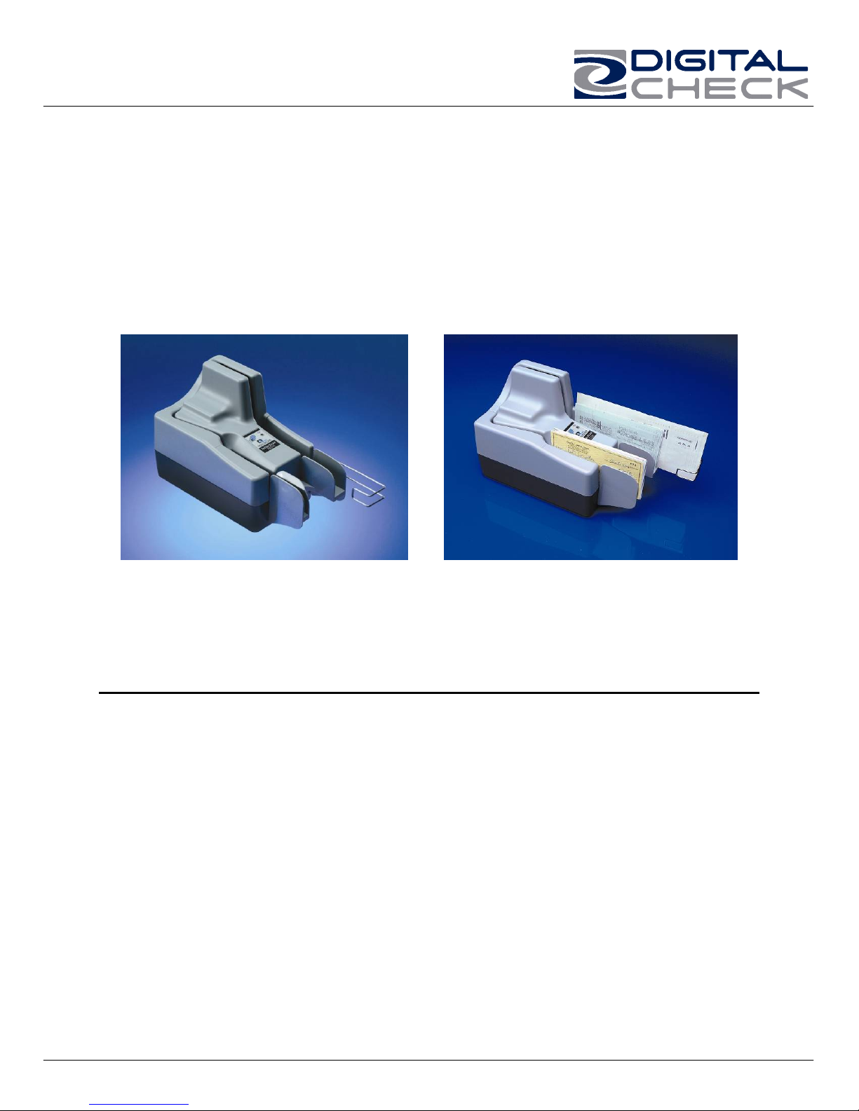
TellerScan® 230 Equipment
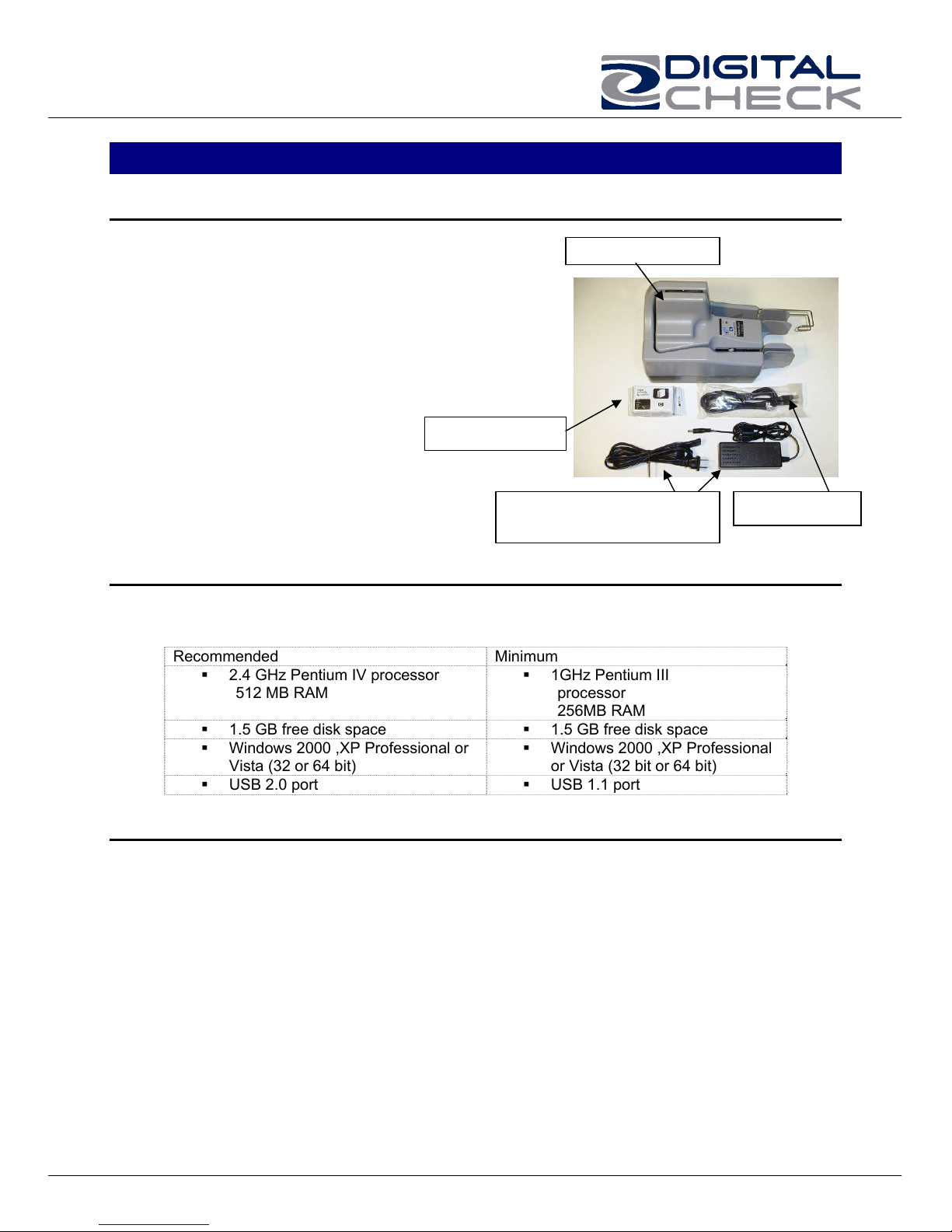
TellerScan® 215 & 230 Equipment Checklist
The TellerScan® 215 & 230 package
includes the following pieces:
TellerScan® 215 or 230 scanner unit
USB 2.0 cable
100v-240v -50/60 hz Voltage Sensing,
external power supply
HP inkjet cartridge (Optional feature)
inkjet cartridge
Power supply & standard
TellerScan® 215 & 230 System Requirements
The following PC specifications are required to operate the TellerScan® 215 or 230 with
your scanning application software:
Recommended Minimum
2.4 GHz Pentium IV processor
512 MB RAM
1.5 GB free disk space 1.5 GB free disk space
Windows 2000 ,XP Professional or
Vista (32 or 64 bit)
USB 2.0 port USB 1.1 port
1GHz Pentium III
processor
256MB RAM
Windows 2000 ,XP Professional
Radio Frequency Interference
The TellerScan® 215 & 230 generates, uses, and can radiate radio frequency energy. If
the unit is not installed and used properly that is, in strict accordance with the
instructions in this manual it may cause harmful interference to radio communications. It
has been tested and found to comply with the limits for Class digital devices pursuant to
Subpart J of Part 15 of FCC Rules, which are designed to provide reasonable protection
against harmful interference when operated in a commercial environment.
Operation of this equipment in a residential area is likely to cause interference, in which
case, the user (at their own expense) will be required to take whatever measures may
be required to correct the interference. The use of shielded cables is required when
connecting this device to any/all peripheral or host devices. Failure to do so may violate
FCC rules.
TS215 or 230
USB cable
US wall plug
or Vista (32 bit or 64 bit)
3
TellerScan 215 & 230 User Manual Rev 050609
r
About the TellerScan® 215 & 230
The TellerScan® 215 & 230 Countertop Check Scanners are an easy-to-use, compact,
scanner that connects to a personal computer (PC). The TellerScan® 215 & 230
automatically scans the front and/or back of checks and also reads the MICR (Magnetic
Ink Character Recognition) code line. The images and data are then transmitted through
a Universal Serial Bus (USB) interface to the PC. The TS215 is a single check at a time
feeder (drop and slide). The TS230 models have an auto feeder that handles up to 50
items.
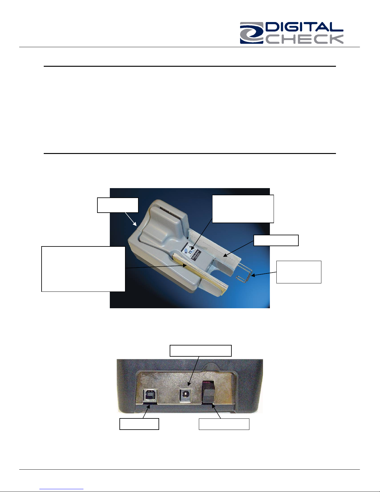
Features of the TellerScan® 215 & 230
Outside the TellerScan® 215 & 230
Fig. 1.
Rear Deck
A single item at a time
feeder (TS 215)
or
Automatic Feeder
(TS 230)
Rear Deck of TellerScan® 215 / 230
Fig. 2
Control Panel
w/ LED Status
Indicators
Exit Pocket
Adjustable
Wire Stop
Power Connecto
USB Port
ON/OFF Switch
4
TellerScan 215 & 230 User Manual Rev 050609
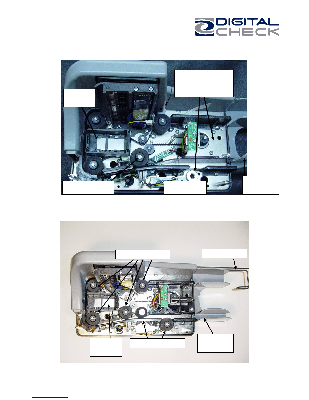
Inside the TellerScan® 215
Fig. 3A
Inkjet
Printer
Fewer Parts.
No Solenoid or
Second Drive Motor
Entry Drive Roller
Inside the TellerScan® 230
Fig. 3B
Main Drive Rollers
Entry Sensor
Entry / Exit
Tray
Exit Stop Wire
Inkjet
Printer
Entry Drive Rollers
5
Entry / Exit
Tray
TellerScan 215 & 230 User Manual Rev 050609
y
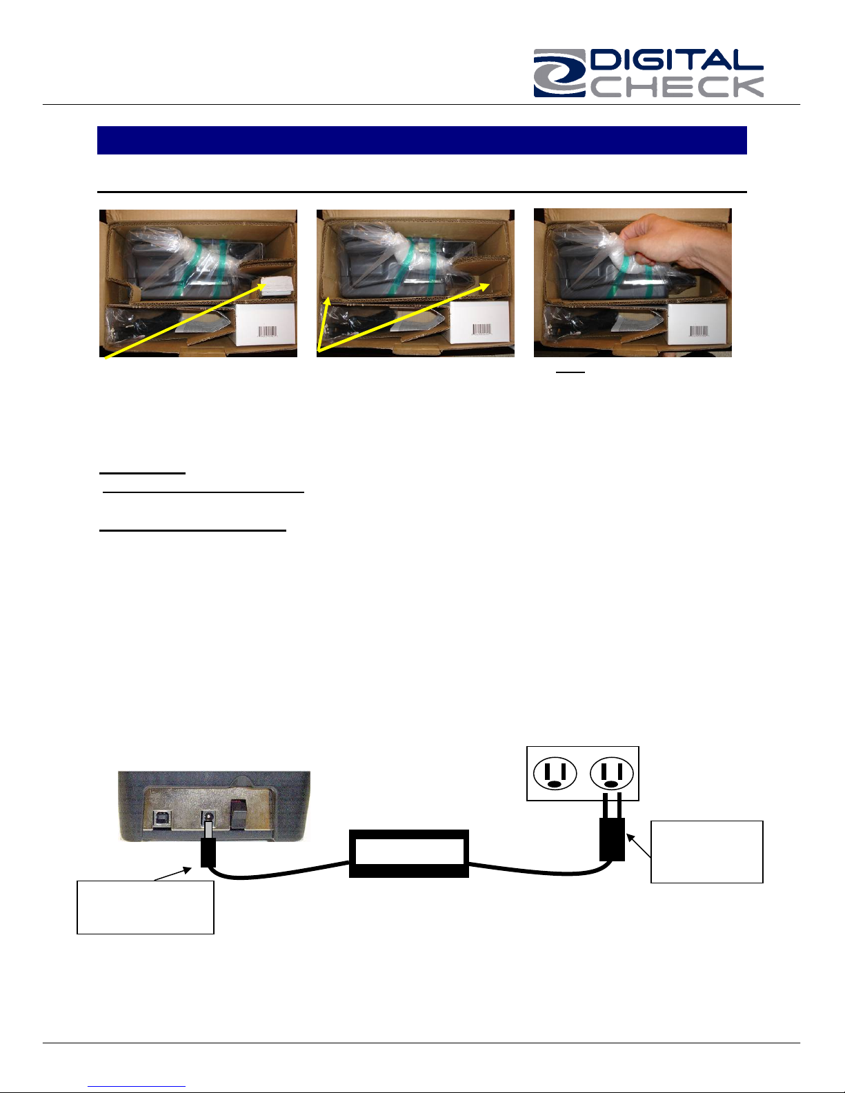
TellerScan® 215 & 230 Installation
Un-Boxing the TellerScan® 215 & 230
Step 1: Step 2: Step 3:
Remove inkjet cartridge
from package slot
Pop-out package corners. Do NOT open the protective
bag. First remove the scanner
from the box by lifting up on
the bag.
WARNING: Before powering on the scanner, you will want to install the USB driver. See
‘Installing the Driver Files’ section on page 8 for instructions.
Setting Up The Scanner
1. Place the unit on a flat surface near the PC and away from direct light.
2. Connect the power cord from the external power supply to the power connector on
the scanner rear deck. (See fig. 2 and fig. 4)
3. Place the external power supply in a ventilated area several feet away from the
scanner and connect to an appropriate source of power.
4. Make sure the TellerScan® 215 or 230 is turned off. Verify that the red power
indicator on the Control Panel is not lit. The power switch is on the rear deck. (See
Fig. 2)
5. Connect the USB cable by plugging it into the port on the rear deck. Do not turn on
the scanner until the driver has been loaded.
Fig. 4
First, plug the power
connector into the
back of the scanner.
Power Suppl
6
Then, plug the
power adaptor
into the wall
receptacle.
 Loading...