

Digital Audio Corporation PCAP II User Manual
PCAP II
PERSONAL COMPUTER AUDIO
PROCESSOR
USER’S MANUAL
DIGITAL AUDIO CORPORATION
A DRI COMPANY


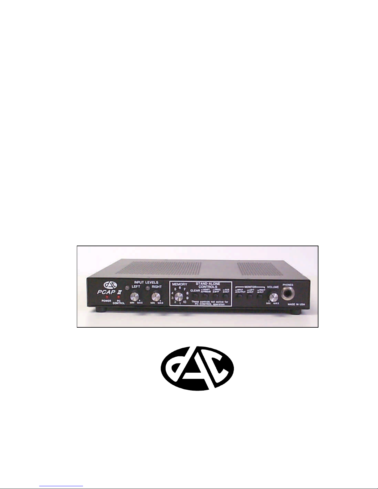
PCAP II
PERSONAL COMPUTER AUDIO
PROCESSOR
User’s Manual
November 2, 1999
Version 12.0
DIGITAL AUDIO CORPORATION
A DRI COMPANY
5121 Holly Ridge Drive
Raleigh, NC 27612
Phone: 919 782 6767
Fax: 919 782 6766
sales@dacaudio.com
www.dacaudio.com
Copyright © 2000 by Digital Audio Corporation.
All rights reserved.


i
TABLE OF CONTENTS
ACKNOWLEDGEMENT........................................................... vi
FOREWORD.........................................................................vii
1 . SYSTEM BASICS .............................................................1
1.1 System Configuration .....................................................1
1.2 External Processor Capability .........................................3
1.3 External Processor Front Panel ......................................4
1.4 External Processor Rear Panel.......................................5
2 . INSTALLATION INSTRUCTIONS .........................................7
2.1 Cautions to User............................................................7
2.2 Installation Procedure.....................................................7
3 . GETTING STARTED ........................................................ 10
3.1 Fast Start ................................................................... 10
3.2 PCAP II Tutorial ........................................................... 14
3.3 Training CD Recordings................................................31
4 . PCAP II SOFTWARE REFERENCE MANUAL................... 33
4.1 Master Control Panel ................................................... 34
4.2 Input and Output Processors ........................................ 38
4.2.1 Input and Output Highpass Filters (HPFs)...............38
4.2.2 Digitally-Controlled Limiter ..................................... 40
4.2.3 Digitally-Controlled AGC........................................42
4.3 DSP Processor Selection ............................................. 44
4.3.1 Filter Selection Window ......................................... 44
4.3.2 Equalizer Selection Window................................... 46
4.4 DSP Filter Control Windows ......................................... 47
4.4.1 2CH Adaptive Filter ............................................... 47
4.4.2 1CH Adaptive Filter ............................................... 51
4.4.3 Lowpass Filter......................................................54
4.4.4 Highpass Filter ..................................................... 57
4.4.5 Bandpass Filter .................................................... 60
4.4.6 Bandstop Filter.....................................................64
4.4.7 Comb Filter .......................................................... 67

ii
4.4.8 Notch Filter...........................................................70
4.4.9 Multiple Notch Filter ..............................................73
4.4.10 Slot Filter............................................................76
4.4.11 Multiple Slot Filter ...............................................79
4.4.12 Spectral Inverse Filter ..........................................82
4.4.13 Hi-Res Graphic Filter ...........................................97
4.4.14 Tri Parametric Filter...........................................106
4.4.15 Limiter/Compressor/Expander............................. 109
4.5 DSP Equalizer Control Windows ................................. 113
4.5.1 20-Band Graphic Equalizer................................... 113
4.5.2 Spectral Graphic Equalizer................................... 117
4.5.3 Dual Parametric Equalizer.................................... 118
4.6 DSP Display Selection...............................................119
4.6.1 Spectrum Analyzer and Coefficient Display
Buttons .............................................................. 119
4.6.2 Display Select Window ........................................ 120
4.6.3 Spectrum Analyzer Window.................................121
4.7 Coefficient Display Window ......................................... 126
4.8 Master Control Pulldown Windows ............................... 130
4.8.1 Saving Setups to Disk Files ................................. 130
4.8.2 Recalling Setups from Disk Files .......................... 132
4.8.3 Viewing DSP Displays ......................................... 134
4.8.4 Storing Setups to External Processor Stand-
Alone Memories..................................................135
4.8.5 Generating Setup Reports .................................... 138
4.8.6 Getting Online Help.............................................138
5 . OPERATING PCAP II STA ND-ALONE............................. 140
6 . PCAP II CUSTOMIZATION OPTIONS .............................. 143
6.1 Configuring PCAP II for Different COM Ports.................143
6.2 Configuring PCAP II for Different Baud Rates ................ 145
6.3 Customizing Screen Colors ......................................... 148
7 . PCAP II SPECIFICATIONS.............................................149

iii
LIST OF FIGURES
Figure 1-1 PCAP II System Configuration...................................................1
Figure 1-2 PCAP II Functional Block Diagram............................................4
Figure 1-3 PCAP II Front Panel......................................................................5
Figure 1-4 PCAP II Rear Panel......................................................................6
Figure 2-1 PCAP II Master Control Icon.......................................................9
Figure 2-2 Master Control Panel...................................................................9
Figure 3-1 PCAP II Connection Diagram...................................................11
Figure 3-2 Fast Start File Pulldown Menu.................................................12
Figure 3-3 Fast Start Open Setup File Window ........................................12
Figure 3-4 Fast Start Recall Setup Alert Message...................................13
Figure 3-5 Tutorial Master Control Panel..................................................14
Figure 3-6 Tutorial Limiter Setup Window.................................................17
Figure 3-7 Tutorial AGC Setup Window.....................................................18
Figure 3-8 Tutorial Filter Selection Window..............................................19
Figure 3-9 Tutorial 1CH Adaptive Filter Control Window........................20
Figure 3-10 Tutorial Lowpass Filter Control Window.............................21
Figure 3-11 Tutorial Equalizer Selection Window....................................22
Figure 3-12 Tutorial 20-Band Graphic Equalizer Control Window.......22
Figure 3-13 Tutorial Store 20-Band Graphic Equalizer Window...........23
Figure 3-14 Tutorial Recall 20-Band Graphic Equalizer Window.........24
Figure 3-15 Tutorial Spectrum Analyzer Window.....................................25
Figure 3-16 Tutorial Display Select Window.............................................27
Figure 3-17 Tutorial File Pulldown Menu...................................................27
Figure 3-18 Tutorial Save Setup File Window..........................................28
Figure 3-19 Tutorial Store in File Name Tex t Box....................................29
Figure 3-20 Tutorial Report Generator Pulldown Menu..........................30
Figure 4-1 PCAP II Master Control Panel..................................................33
Figure 4-2 Input and Output HPF Buttons .................................................38
Figure 4-3 Input HPF Setup Window..........................................................39
Figure 4-4 Limiter Button..............................................................................40
Figure 4-5 Limiter Setup Window...............................................................41
Figure 4-6 AGC Button..................................................................................42
Figure 4-7 AGC Setup Window....................................................................43
Figure 4-8 Filter Selection Window.............................................................44
Figure 4-9 Filter Select Combo Box ............................................................45
Figure 4-10 Equalizer Selection Window..................................................46
Figure 4-11 2CH Adaptive Filter Control Window....................................47
Figure 4-12 1CH Adaptive Filter Control Window....................................51
Figure 4-13 Lowpass Filter Control Window............................................54
Figure 4-14 Lowpass Filter Graphical Description.................................56
Figure 4-15 Highpass Filter Control Window...........................................57
Figure 4-16 Highpass Filter Graphical Description................................59
Figure 4-17 Bandpass Filter Control Window ..........................................61
Figure 4-18 Bandpass Filter Graphical Description...............................63

iv
Figure 4-19 Bandstop Filter Control Window...........................................65
Figure 4-20 Bandstop Filter Graphical Description................................66
Figure 4-21 Comb Filter Control Window.................................................67
Figure 4-22 Comb Filter Graphical Description.......................................70
Figure 4-23 Notch Filter Control Window..................................................71
Figure 4-24 Notch Filter Graphical Description.......................................72
Figure 4-25 Multiple Notch Filter Control Window...................................74
Figure 4-26 Multiple Notch Filter Graphical Description........................75
Figure 4-27 Slot Filter Control Window......................................................77
Figure 4-28 Slot Filter Graphical Description...........................................78
Figure 4-29. Multiple Slot Filter Control Window......................................80
Figure 4-30 Multiple Slot Filter Graphical Description............................81
Figure 4-31 Basic Process of Spectral Inverse Filter.............................83
Figure 4-32 SIF Control Window When Equalize Voice Selected........84
Figure 4-33 SIF Control Window When Attack Noise Selected...........87
Figure 4-34 Spectral Inverse Filter Store Window...................................89
Figure 4-35 Spectral Inverse Filter Recall Window.................................90
Figure 4-36 EQ Voice operation, EQ Range set to 10dB, Output
Shape set to Flat.......................................................................91
Figure 4-37 SIF with EQ Range set to 20dB.............................................91
Figure 4-38 SIF with EQ Range set to 50dB.............................................94
Figure 4-39 Attack Noise operation, Attack Range set to 30dB.........95
Figure 4-40 SIF with Output Shape set to Voice.....................................96
Figure 4-41 Hi-Res Graphic Filter Window...............................................97
Figure 4-42 Hi-Res Filter Store Window...................................................99
Figure 4-43 Hi-Res Graphic Filter Recall Window................................100
Figure 4-44 New Hi-Res Graphic Filter Display....................................101
Figure 4-45 Hi-Res Graphic Draw in Progress.....................................102
Figure 4-46 Completed Hi-Res Graphic Draw......................................102
Figure 4-47 Hi-Res Graphic Edit Window...............................................103
Figure 4-48 Hi-Res Graphic Define Edit Region...................................104
Figure 4-49 Hi-Res Edit In Progress.......................................................104
Figure 4-50 Completed Hi-Res Graphic Edit.........................................105
Figure 4-51 Normalized Hi-Res Graphic Filter......................................105
Figure 4-52 Tri Parametric Filter...............................................................107
Figure 4-53 Graphical Representation of a Parametric Filter.............108
Figure 4-54 Limiter/Compressor/Expander Control Window.............111
Figure 4-55 20-Band Graphic Equalizer Control Window....................114
Figure 4-56 Dual Parametric Filter...........................................................118
Figure 4-57 Spectrum Analyzer and Coefficient Display Buttons.......119
Figure 4-58 Display Select Window.........................................................120
Figure 4-59 Spectrum Analyzer Window.................................................122
Figure 4-60 Coefficient Display Window.................................................127
Figure 4-61 Save Setup File Window.......................................................131
Figure 4-62 Open Setup File Window......................................................132
Figure 4-63 Stand-Alone Pulldown Menu...............................................136
Figure 4-64 Auxiliary Switch Function Window.......................................136

v
Figure 4-65 Report-Generator Pulldown Menu.....................................138
Figure 4-66 Help Pulldown Menu............................................................139
Figure 6-1 ComPort Selection Menu.......................................................143
Figure 6-2 Baud Rate Selection Menu....................................................146

vi
ACKNOWLEDGEMENT
The Personal Computer Audio Processor, model PCAP II, is a
second generation PC-based digital audio filtering system. Like its
predecessor, the Personal Computer Digital Filter, this product was
inspired by and significantly contributed to by Mr. James P. Foye of
the United States Postal Service. Mr. Foye made numerous valuable
technical and applications suggestions during the development of the
PCAP. He also performed the critical tasks of beta testing. For
those contributions Digital Audio Corporation is most grateful.

vii
FOREWORD
The PCAP II Personal Computer Audio Processor is a new and
powerful digital audio processor. The PCAP II offers the following
advantages over other PC-based audio processors:
• Compact field-deployable packaging
• Direct digital audio input/output
• Both mono and stereo signal processing
• Up to nine stages of enhancement processing
• All WindowsTM-based control: versatile configuration and
easy adjustment
• All signal processing contained in an external unit; interfaces
to PC serial port with a single cable
• Laptop or desktop comput er control
• Built-in dual channel FFT spectrum analyzer
• Built-in digital filter coefficient display
• Disk file storage/recall of filter setups
• Stand-alone operation allowing the PCAP II to be operated at
desired settings without PC
• Report generator for hardcopy printouts and word processor
files of filter setups
• Unmatched flexibility and performance
The PCAP II is applicable to a broad spectrum of voice and similar
audio signals. It attacks a wide variety of noises in forensic
applications. Body microphone, cassette, microcassette, telephone,
broadcast, and hi-fi audio signals can all be processed efficiently,
since the PCAP II can be set to operate at bandwidths of 3.2, 5.4,
6.5, 8.0, 11, and 16 kHz.

viii
The PCAP II is designed to replace an entire rack of audio processing
equipment. With monophonic signals, as many as nine sequential
stages of processing (five of which are digital) can be performed
simultaneously. With stereo signals, seven sequential stages of
stereo processing (three of which are digital) for each channel are
also available. The digital stages can implement a broad selection of
filter types.
An easy-to-use Microsoft Windows-based Master Control program
allows intuitive control of the entire process, including bandwidth
selection, mono/stereo configuration, and number of digital
processing stages. Individual process controls and filter modes for
each digital stage are easily specified. Input and output level
bargraphs are displayed, and the signal frequency spectrum at any
point in the process can be displayed utilizing the PCAP II's built-in
spectrum analyzer.

1
1. SYSTEM BASICS
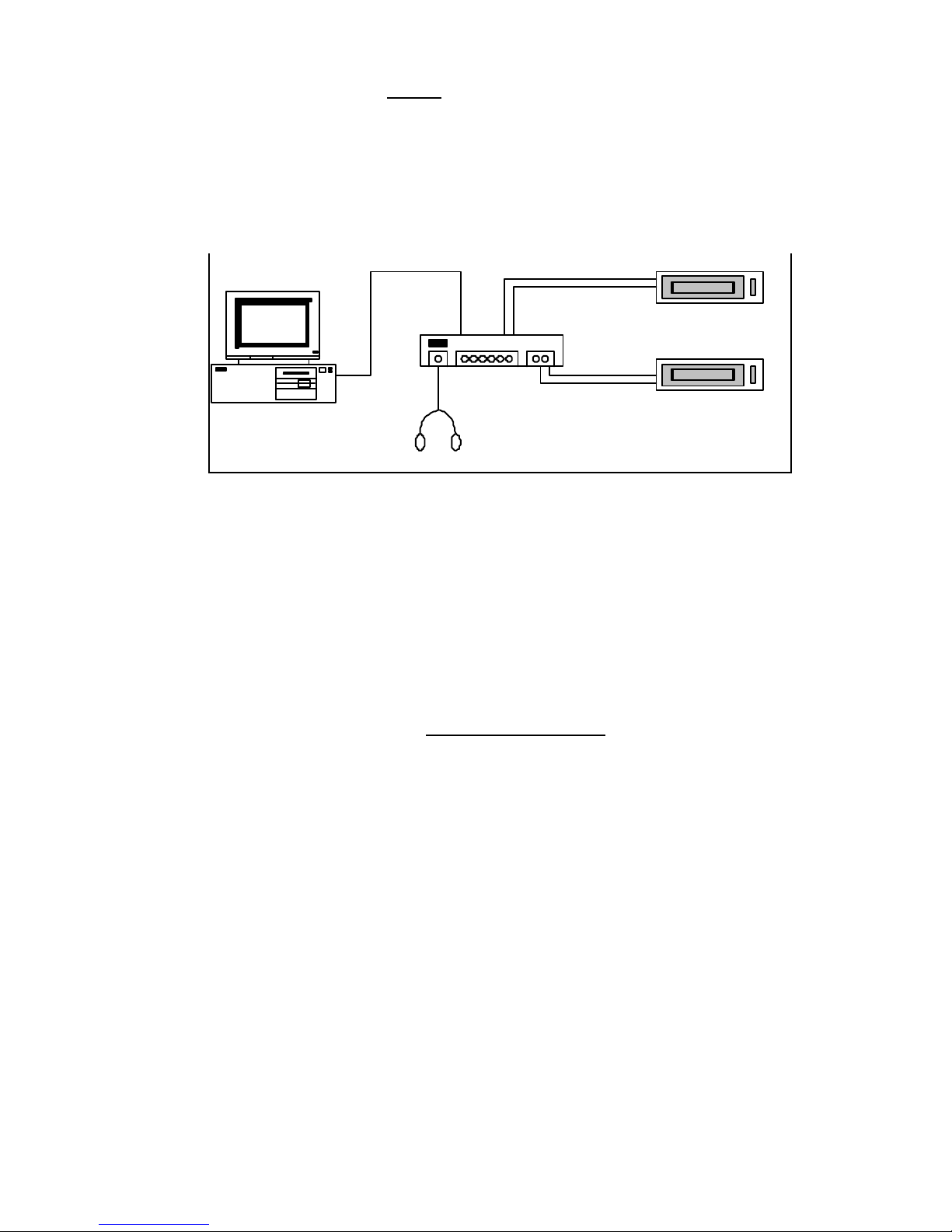
1.1 System Configuration
The basic configuration of the PCAP II system is illustrated in the
following (Figure 1-1)
Computer
PCAP II
Enhanced Audio Recorder
Source Audio Player
RS-232
Headphones
Figure 1-1 PCAP II System Configuration
The PCAP II Master Control program is written to be run on any
Microsoft Windows 95/98/NT IBM PC-compatible computer. For best
performance the following minimum system is rec ommended:
• Intel Pentium CPU processor (at least 166 MHz)
• 32 Megabytes of RAM
• 2.1 GB hard disk drive
• CD-ROM Drive
• 800x600 color SVGA display with 0.28 or better dot pitch
• Two-button mouse
• At least one spare RS232 port
• Laser or dot -matrix printer
Performance will improve with higher speed CPUs.

2

3
1.2 External Processor Capability
The PCAP II EXTERNAL PROCESSOR unit is a high-performance,
self-contained digital signal processor and contains 27 DSP
microprocessors, which are allocated as follows:
• Sixteen FIR filter processors which can be configured as 1, 2,
3, or 4 independent audio processors. These flexible
processors may be combined into mono and stereo
configurations. Any of the processors may be configured as
an adaptive or adjustable digital filter.
• Two FIR fixed filter processors which are dedicated as output
spectral equalizers.
• Two FIR fixed filter processors which perform interpolation
and decimation filters.
• Four FIR fixed filter processors which perform input and
output highpass filters.
• Three general-purpose microprocessors which execute
special DSP software, implement the dual FFT spectrum
analyzer, communicate with the PC via RS232, and provide
system control.
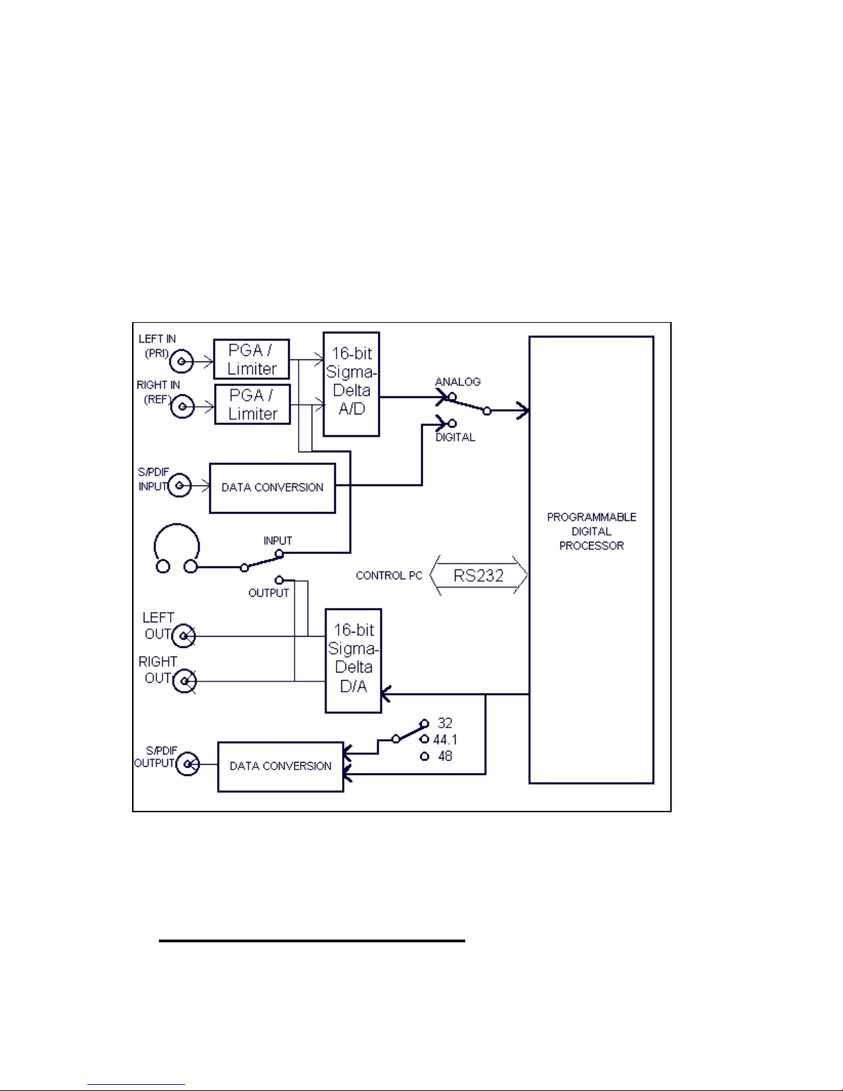
Analog-to-digital and digital-to-analog conversion is performed by
stereo, 16-bit, sigma-delta converters which perform 64x
oversampling.
The base sample rate is adjustable from 7.2 kHz (3.2 kHz bandwidth)
to 36 kHz (16 kHz bandwidth). All sample rates are exact multiples
of 50 Hz and 60 Hz, allowing maximum filter performance at
harmonics of these frequencies.
Digital, 200Hz highpass filters are provided on all inputs (pre-process)
and on all outputs (post-process) to remove rumble and other lowfrequency noises.
Microprocessor-controlled limiters are provided on both analog inputs
to prevent overload. When using the S/PDIF digital inputs, the
limiters prevent the digital signal from exceeding a specified level.
4
Digital AGCs are provided to compensate for near party/ far party
voice level differences.
Ten stand-alone nonvolatile memories are provided for onboard
storage and recall of filter setups created by the PCAP II Master
Control Program. This allows the external processor to be operated
in any of four previously-stored setups without being connected to a
PC.
For a simplified functional block diagram, see Figure 1-2.
Figure 1-2 PCAP II Functional Block Diagram
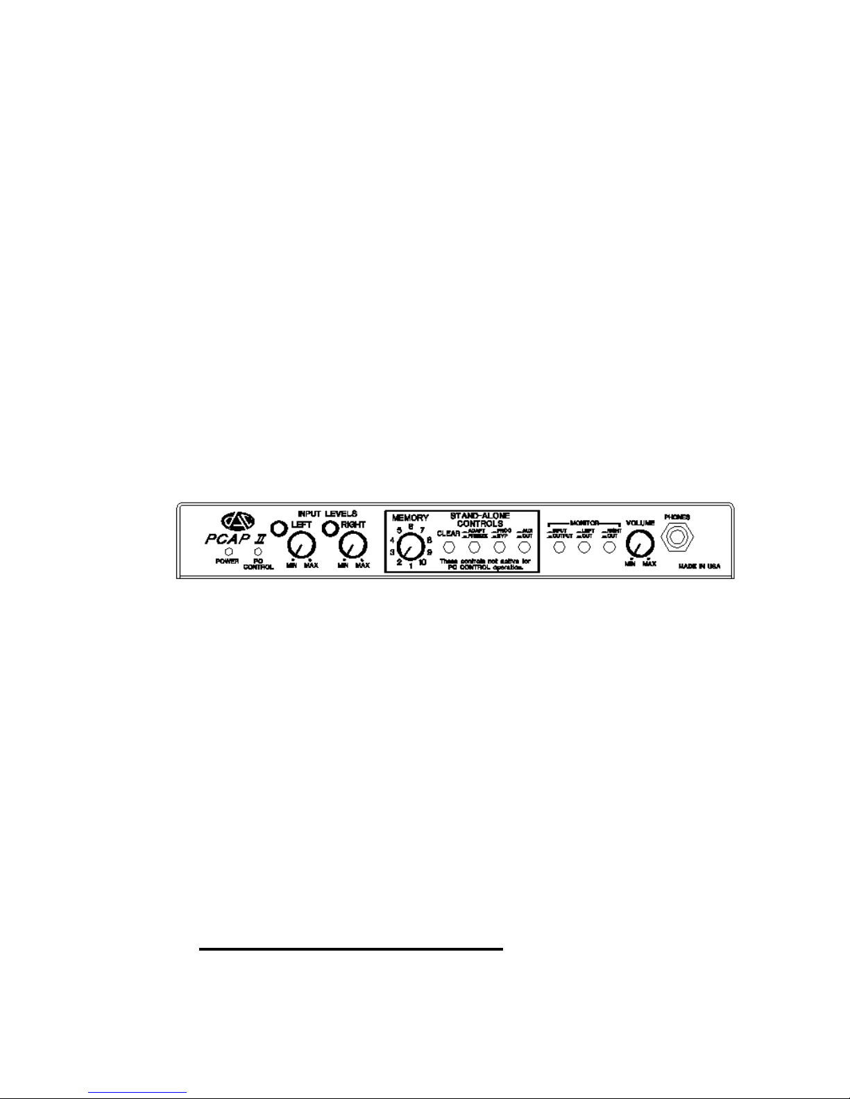
1.3 External Processor Front Panel
5
The front panel controls are arranged into three logical groups:
headphone MONITOR controls, STAND-ALONE controls, and INPUT
LEVEL controls.
The MONITOR controls allow the user to listen to either the INPUT or
OUTPUT signals with a pair of stereo headphones connected to the
1/4" PHONES jack. Switching the headphones between the INPUT
and OUTPUT signals does not alter the signal flow to the LEFT OUT
and RIGHT OUT line output RCA connectors. The VOLUME level can
be adjusted to a comfortable listening level.
The STAND-ALONE CONTROLS allow the user to select and run one
of ten previously-programmed filter setups stored in internal
nonvolatile memory. For complete instructions on using the STANDALONE memories, see Sections 4.8.4 and 5.0.
The front panel of the PCAP II external processor appears as follows
(Figure 1-3):
The LEFT and RIGHT INPUT LEVEL controls allow the user to adjust
the input signals to the proper level for processing. Tricolor LEDs are
provided to indicate signal levels; when the LEDs are GREEN, the
signals are at the proper levels, while YELLOW indicates caution.
RED indicates potential input overload. Input signal levels are also
indicated by the displayed bargraphs on the PCAP II Master Control
Panel (See Section 3.2 PCAP II Tutorial).
The POWER led indicates when power is supplied to the unit, while
the PC CONTROL led indicates when the unit is under control of the
PCAP II Master Control software.
1.4 External Processor Rear Panel
The rear panel of the PCAP II external processor appears as follows
(Figure 1-4):
Figure 1-3 PCAP II Front Panel

6
DC power is provided to the unit through the external POWER jack by
either the supplied external AC adaptor or direct connection to a 9 18 VDC source. The POWER switch must be switched to the ON
position in order for the unit to operate.
A 9-pin RS232 jack is provided to connect the PCAP II external
processor to a computer using the supplied cable. In this new version
of the PCAP, the unit is automatically put into PC CONTROL mode
when characters are received over the RS232 connector using the
PCAP II Master Control software. After terminating the software, the
unit will return to stand alone mode after about 10 seconds (PC
CONTROL mode is indicated by the LED on the front panel).
Analog stereo inputs and outputs are provided on the rear panel via
RCA jacks. As a new feature, the PCAP II includes digital S/PDIF
input and output jacks as well. Using the INPUT SELECT switch, the
user can select which type of input (ANALOG or DIGITAL) to use.
Both the ANALOG and DIGITAL outputs are always active. The
output rate of the digital output can be selected using the OUTPUT
RATE switch.
Figure 1-4 PCAP II Rear Panel

7
2. INSTALLATION INSTRUCTIONS
2.1 Cautions to User
To install the PCAP II hardware and software, the user must have a
good working knowledge of IBM PC-compatible computers and the
Microsoft Windows operating environment. Particularly, the user
must know which RS232 COM ports are COM1, COM2, COM3, etc.
Usually, a serial mouse will be installed on COM1, leaving COM2
available for connecting the PCAP II external processor. If COM2 is
not available in the user's PC, it will be necessary to reconfigure the
PCAP II software COM port selection by performing the procedure in
Section 6.1 after completing the installation procedure in Section 2.2.
The Microsoft Windows operating environment must be in place prior
to installing the PCAP II. All video drivers, device drivers, etc. must
be installed and operating properly.
For advanced users who need to configure the PCAP II to operate at
RS232 symbol rates slower than 38400 baud (factory default), please
see Section 6.2. Note: Altering the baud rate setting is not
recommended.
2.2 Installation Procedure
1. Carefully remove the PCAP II external processor from the
shipping container. Confirm that the AC power adapter,
RS232 cables (2), demonstrator audio CD, and software
disk(s) are included. Also confirm that any optional
accessories are included.
2. Connect the AC power cord to the PCAP II rear panel
POWER connector. Keep the POWER switch OFF for now.
3. With the PCAP II POWER switch OFF, plug the AC power
adapter into an AC outlet.
4. With the computer turned OFF, connect the supplied RS232
cable between the CONTROL PC RS232 connector on the
PCAP II rear panel and the desired computer COM port (You

8
may need to purchase an adapter if the COM port has 25
pins).
5. Now that they are connected together, switch ON both the
PCAP II and the computer.
6. Once Windows has booted up (Windows 95/98 or NT), insert
the PCAP II Master Control software CD into the CD-ROM
drive in your PC. The installation program should
automatically run. If not, use the Run command in the
Windows Start menu to start the installation program.
If the machine you wish to install the PCAP II Master Control
Software does not have a CD-ROM then, on a machine that
does have a CD-ROM, insert the CD and run Windows
Explorer. Note: The installation software will most likely run
automatically. If it does exit it by clicking the “Cancel”
button. You can run Windows Explorer by clicking on the
Start menu and then on Run and typing “explorer” or by
clicking Start->Programs->Windows Explorer. Once
Windows Explorer has opened, click on the CD-ROM drive
that contains the PCAP II Master Control Software to view the
contents of it. You will see a folder labeled “Installation
Diskettes”. Open this folder and you will see several other
folders and one file labeled “MakeDisks.bat”. Double-click on
this file and a utility will run that will guide you through
making installation diskettes. Make sure that the disks you
use are formatted and do not contain any other files.
To start the installation from a diskette, insert the first
diskette into the floppy drive . Click on the Start Menu and
then on Run. Type:
A:SETUP<enter>
in the Command Line text box.
7. The PCAP II Setup Utility will now install the PCAP II Master
Control software on your PC's hard disk. Please follow any
instructions displayed by the Setup Utility.
Once the Setup Utility has completed installing the software,
the icon in Figure 2-1 should appear on your screen:
9
Figure 2-1 PCAP II Master Control Icon
Double click on this icon now to run the program. A screen
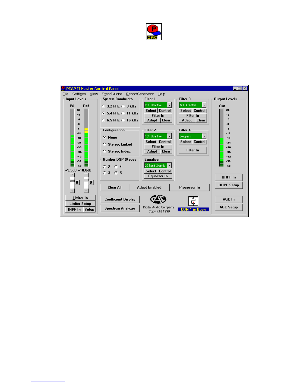
similar to Figure 2-2 should appear:
Figure 2-2 Master Control Panel
If an error message is displayed, it is possible that the
software is not configured for the correct COM port (software
defaults to COM2). If you know to which COM port the
PCAP II external processor is connected, configure the
PCAP II Master Control program for the correct COM port by
following the procedure in Section 6.1.
The PCAP II system should now be installed and ready to run.

10
3. GETTING STARTED
Operation of the PCAP II system is highly intuitive; most operators
can quickly learn while using. The Fast Start procedure in Section
3.1 should allow first time users to quickly begin processing audio
and utilizing the basic enhancement capabilities of the PCAP II
system. For a lesson in operating the PCAP II controls, it is
recommended that the user also complete the PCAP II Tutorial in
Section 3.2. Section 3.3 applies the PCAP II to different noise
problems contained on the PCAP II Tr aining CD.
In the following sections the Source Audio Player and an Enhanced
Audio Recorder will be referred to. The Source Audio Player can be
any type of playback unit such as a CD, Mini-Disk, Micro-cassette, or
Digital Audio Tape (DAT) playback unit. The Enhanced Audio
Recorder can be any type of audio recorder such as a CD, Mini-disk,
Micro-cassette, or DAT recording device.
Always consider that the quality of the playback and recording media
will limit the quality of the processed and enhanced audio. The
recommended device is a DAT recorder with digital inputs because
the PCAP can transfer the audio digitally. DAT recorders have
excellent bandwidth and signal-to-noise (SNR) ratio.
3.1 Fast Start
Fast start the PCAP II as follows:
1. Connect the LEFT and RIGHT channel line-level audio
outputs (AUDIO OUT jacks) of your Source Audio Player to
the LEFT IN and RIGHT IN RCA jacks on the PCAP II
external processor rear panel as shown in Figure 3-1. Note
that the RIGHT IN signal is only used in stereo configuration
and with the 2CH Adaptive Filter in mono configuration.
2. If you wish to record the enhanced audio, connect the linelevel audio inputs (AUDIO IN jacks) of your Enhanced Audio
Recorder to the LEFT OUT and RIGHT OUT RCA jacks on
the PCAP II external processor rear panel as shown in Figure
3-1.
11
3. Connect your stereo headphones to the PHONES jack on the
PCAP II external processor front panel as shown in Figure
3-1. Turn the phones VOLUME control to MIN. It is also
recommended that headphones be connected to the
Enhanced Audio Recorder's headphone jack to confirm that
the output signal is being properly recorded.
4. With the PCAP II installation procedure in Section 2.2
complete, run the PCAP II Master Control program by
double-clicking on the screen icon. It may require several
seconds for the program to load and initialize the external
unit.
5. With the PCAP II Master Control Panel displayed on your PC
screen, insert the PCAP II Training CD into the Source Audio
Player, then press the PLAY button.
6. Adjust the LEFT and RIGHT INPUT LEVEL controls on the
PCAP II external processor front panel until the Input Levels
bargraphs on the PCAP II Master Control Panel indicate
GREEN with occasional peaks in the YELLOW range. Note
that some mono segments of the audio may not have audio
recorded on them.
7. With the phones LEVEL initially set to MIN, place the stereo
headphones on your ears and slowly adjust the phones
LEVEL for comfortable listening.
NOTE: If you wish to listen to the unprocessed audio going
into the PCAP II, toggle the MONITOR switch on the PCAP II
external processor to INPUT. To listen to the PCAP II output,
toggle the MONITOR switch to OUTPUT.
Computer
PCAP II
Enhanced Audio Recorder
Source Audio Player
RS-232
Headphones
Figure 3-1 PCAP II Connection Diagram
12
If you wish at this point to discontinue the Fast Start procedure and
experiment with the PCAP II Master Control Panel on your own,
please feel free to do so - you will not damage anything. If, however,
you still feel unsure of what to do, please continue the Fast Start
procedure as follows:
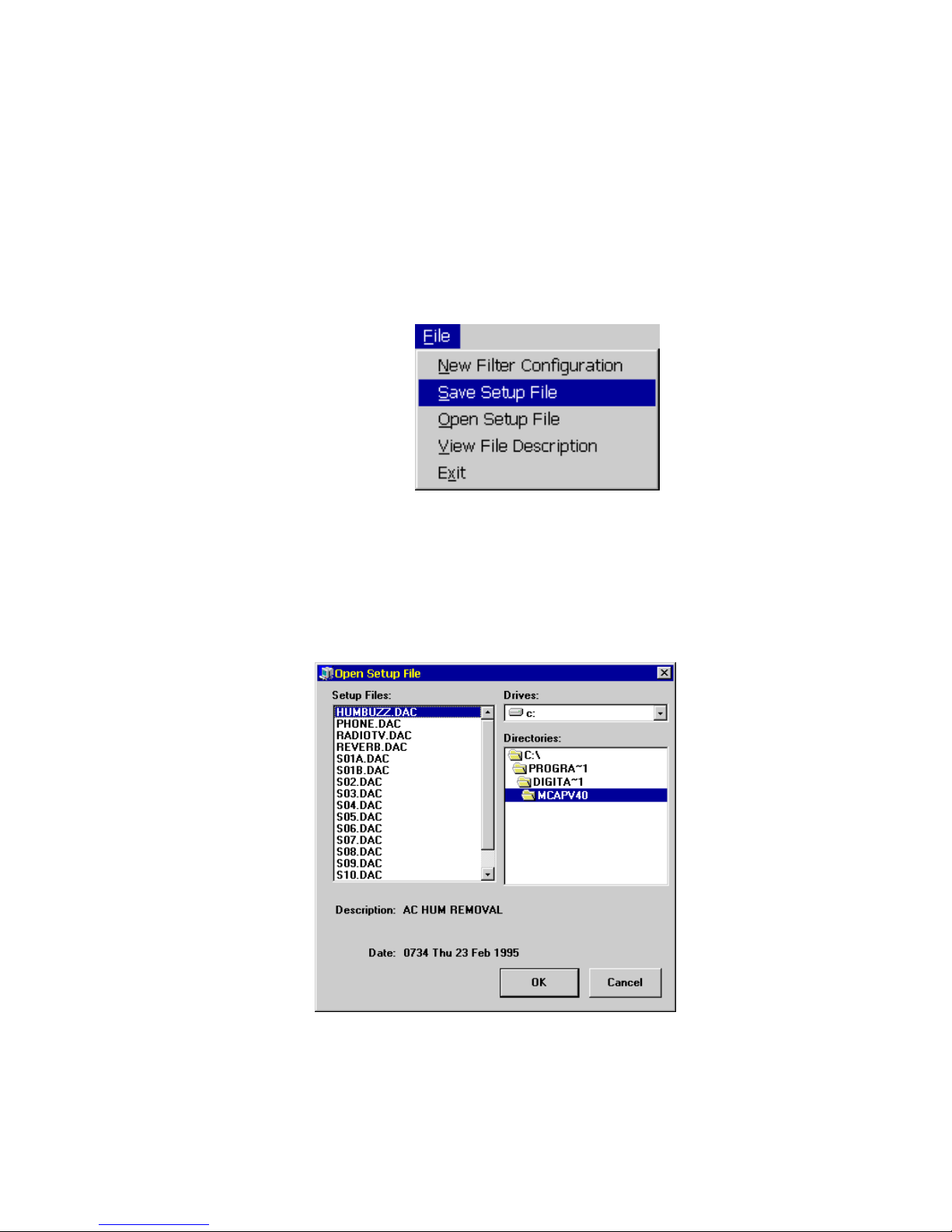
8. From the PCAP II Master Control Panel menu bar, click on
File. Th is will cause the following pulldown menu to appear
9. Click on Open Setup File to bring up a window similar to
Figure 3-3:
10. The Setup Files box should contain a list of all PCAP II
setup files on your hard disk. The installation procedure in
Section 2.2 should have installed several setup files which
Figure 3-2 Fast Start File Pulldown Menu
Figure 3-3 Fast Start Open Setup File Window
13
have the .DAC extension onto your hard disk. Included in
these setup files are:
PHONE.DAC - Telephone audio enhancement
BODYMIKE.DAC - Body microphone/recorder audio
enhancement
HUMBUZZ.DAC - Powerline hum and buzz removal
REVERB.DAC - Cancellation of room echoes and
reverberations
RADIOTV.DAC - Cancellation of radio and/or TV
audio from live or recorded audio
using a reference
These basic setups should be able to enhance most voice
recordings. To begin processing audio with one of these
setups, open the desired setup file by clicking on its filename
in the Setup Files box, then click on OK.
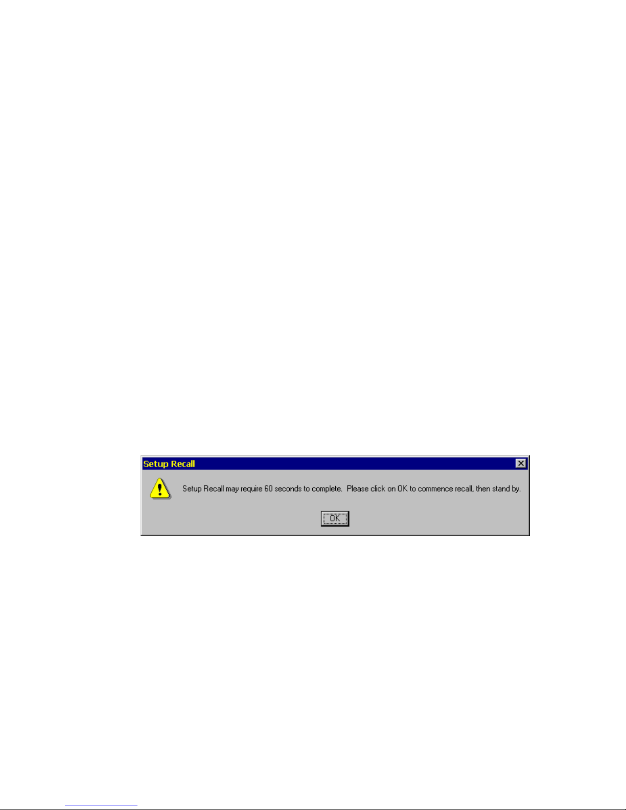
11. The following message will now appear to alert you that 60
seconds may be required to open your setup fi le (Figure 3-4):
Click on OK to commence the opening (recall) of the setup
file. An "hourglass" mouse cursor will now appear, indicating
that the PCAP II is busy recalling a setup file.
12. When the mouse cursor returns to normal, the setup file will
be complete. Toggle the MONITOR switch on the PCAP II
external processor between INPUT and OUTPUT to hear the
difference between the unprocessed input signal and the
processed output signal.
Figure 3-4 Fast Start Recall Setup Alert Message
14
Feel free to experiment with the PCAP II Master Control Panel
settings - you may open the original setup at any time by repeating
steps 8-12. If you wish to try loading any of the other basic setup
files, repeat steps 8-12.
Once you become comfortable recalling the basic setup files, it is
strongly recommended that you complete the PCAP II Tutorial in
Section 3.2.
3.2 PCAP II Tutorial
This brief tutorial should allow the user to quickly learn the basic
operation of the PCAP II 's controls. It should require about 1 hour to
complete, yet it demonstrates the basic functionality.
NOTE: A subset of the PCAP II's functions are utilized in this tutorial.
Refer to Chapter 4 for detailed information on all of the PCAP II 's
functions.
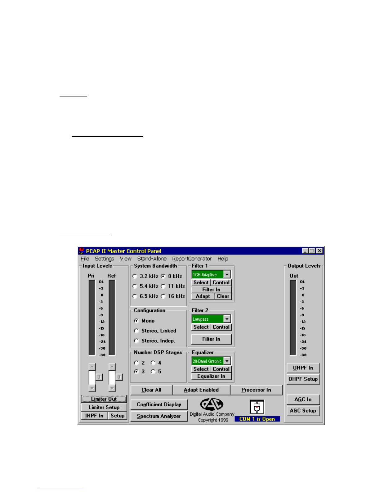
Tutorial Steps:
Figure 3-5 Tutorial Master Control Panel

15
1. With the installation procedure in Section 2.2 completed, run
the PCAP II Master Control program by double clicking the
PCAP II Master Control icon in Microsoft Windows. A
window similar to Figure 3-5 Tutorial Master Control Panel will
appear:
This is the Master Control Panel, from which all features can
be accessed. The Master Control Panel is organized
logically from left to right, with audio input controls at the far
left, digital processing controls in the middle, and audio
output controls at the far right.
2. Use the mouse* to set the Input HPF In/Out, Limiter
In/Out, Output HPF In/Out, AGC In/Out, System
Bandwidth, Configuration, Number DSP Stages, Adapt
Enabled/Disabled, and Processor In/Out buttons as they
are shown in Figure 3-5. Do not set up the Filter blocks and
Equalizer blocks at this time.
3. Connect the LEFT and RIGHT outputs (AUDIO OUT jacks) of
the audio player to the LEFT and RIGHT ANALOG INPUTS
jacks on the PCAP II external processor; make sure that the
INPUT SELECT switch is set to ANALOG. Insert the PCAP
II Training Tape and rewind to the beginning.
4. Connect a pair of stereo headphones to the PHONES jack on
the PCAP II external processor. Switch the MONITOR
switches to INPUT/LEFT/RIGHT and adjust the headphone
LEVEL control to MIN. Mono headphones should not be
used as possible damage to the headphone amplifier could
occur.
5. Play the demonstration audio CD. Adjust the INPUT
LEVELS controls on the PCAP II ex ternal processor so that
the peak audio level, as measured by the bargraphs on the
Master Control Panel, is approximately -6 dB.
___________________________________
*Additionally, the control buttons may be selected with the <Tab> key highlighting
that button. Once selected, the button may be toggled with the <Space> or <Enter>
keys. Fast keys are also available for buttons having an underlined letter.
Pressing <Alt> in combination with the letter causes that button to toggle, e.g.
pressing <Alt-P> toggles the Processor In/Out button.

16
NOTE: The audio needs to be playing throughout this tutorial.
If you reach the end of the audio before completing the
tutorial, please restart it (some CD players allow a track to be
continually repeated.)
6. With the demonstration audio CD playing, slowly increase
the headphone VOLUME until audio can be clearly heard in
the left ear (no signal in the right ear).
7. Click on the Filter button in both the Filter 1 block and the
Filter 2 block until both buttons indicate Filter Out
(bypassed).
8. Click on the Equalizer button in the Equalizer block until the
button indicates Equalizer Out (bypassed).
9. Switch the MONITOR switches on the PCAP II external
processor to OUTPUT/LEFT/RIGHT. Readjust the
headphone VOLUME if necessary.
10. Switch the Input HPF in and out by clicking on the Input
HPF button in the Input Levels block. You should hear the
low frequency effects of this control. Restore the button to
the Input HPF Out indication.
11. Switch the Output HPF in and out by clicking on the Output
HPF button in the Output Levels block. You should hear the
low frequency effects of this control. Restore the button to
the Output HPF Out indication.
17
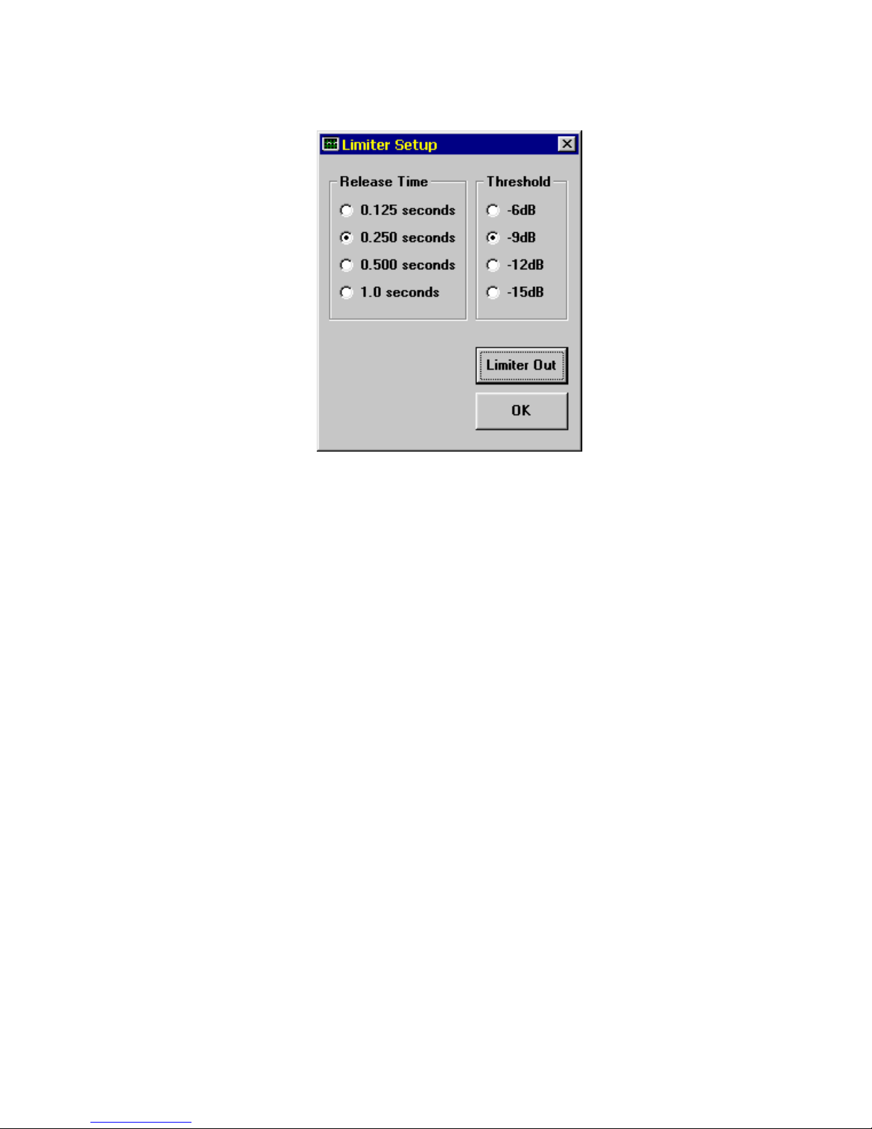
12. Click on the Limiter Setup button in the Input Levels block.
The following window (Figure 3-6) will appear:
13. Use the mouse to set the Release Time to 0.250 seconds
and the Threshold to -9dB, as shown in Figure 3-6. Click on
OK when done*.
14. Adjust the headphone VOLUME control to MIN. Increase
both INPUT LEVELS controls fully clockwise to the MAX
position. This should cause the PCAP II audio inputs to
overload (this will not damage the unit but will distort the
audio). The tricolor level LED should indicate RED on peaks,
and the Left bargraph in the Input Levels block should be
frequently popping up into the RED zone, indicating overload.
15. Slowly increase the headphone VOLUME until distorted
audio can be clearly heard.
16. Switch the Limiter In and Out by clicking on the Limiter
button in the Input Levels block. You should notice the
indicated bargraph levels decrease to -9dB and the audio
quality (as heard through the headphones) dramatically
___________________________________
*If you try to click anywhere on the Master Control Panel while a control window
(such as the Limiter Setup window) is displayed, a warning beep will sound,
indicating that you need to first close the control window by clicking the OK button.
Figure 3-6 Tutorial Limiter Setup Window
18
improve whenever the button indicates Limiter In. The input
limiter is electronically lowering the INPUT LEVELS to avoid
overload. Restore the button to the Limiter Out position and
restore the INPUT LEVELS controls to normal level.
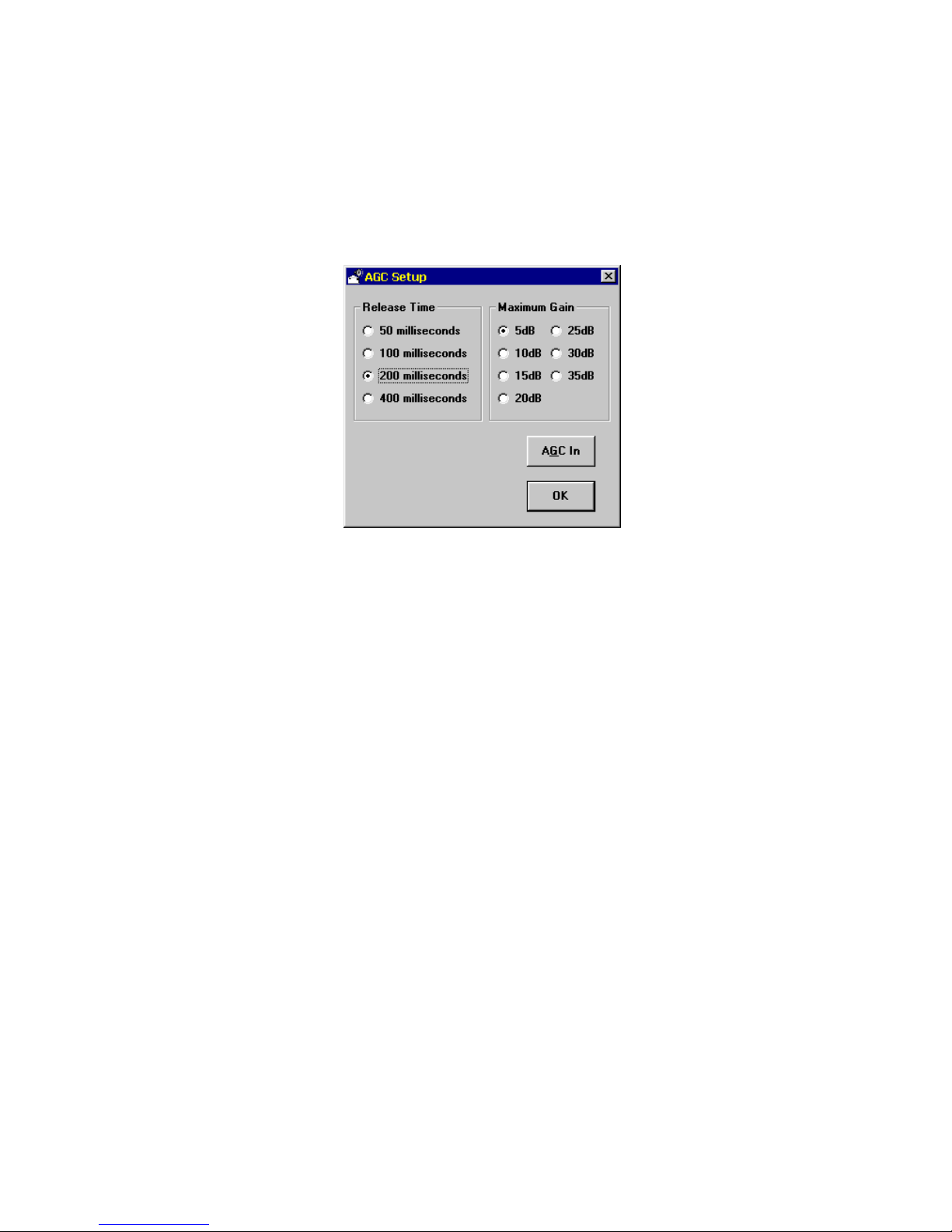
17. Click on the AGC Setup button in the Output Levels block.
The following window (Figure 3-7) will appear:
Use the mouse to set the Release Time to 200 milliseconds
and the Maximum Gain to 20dB, as shown in Figure 3-7.
Click on OK when done.
18. Reduce the INPUT LEVEL until the Output Level Bargraphs
indicate a peak signal level of approximately -36dB.
19. Switch the AGC in and out by clicking on the AGC button in
the Output Levels block. You should notice the output level
bargraphs slowly increase to approximately -18dB indicated
level and the audio level as heard through the headphones
dramatically increase whenever the button indicates AGC In.
The AGC attempts to make the Output Level constant and is
useful in near party/far party situations. Restore the button to
the AGC Out indication, and restore the INPUT LEVELS
controls to normal level.
Figure 3-7 Tutorial AGC Setup Window
 Loading...