

Digital audio THE ADDA 2408 Quick Start Manual
THE ADDA 2408
“QuickStart”
Please read the manual and/or ADDA2408
presentation for further information, both available at
www.digitalaudio.dk
1

Contents
3. Connecting the cables
4. Turn on the ADDA 2408
5. Basic structure
6. Overview
7. Short Cuts
8. AD-DD Source Button
9. World-Class Mic Preamp
10. Synchronization Options
11. Delay, Low cut and Phase
12. The DA Source Button
13. The Monitor Mixer
14. Head Phone Amp
15. Sync alarm
16. Overview: The Menu Structure
17. Precise Line Level Adjustment
18. I/O modules
19. The 4 ch. DA converter interface
20. The ProTools Mix 24 compatible I/O’s.
21. ProTools HD
22. The TDIF interface
23. The ADAT interface
24. The AES, S/PDIF interfaces
2
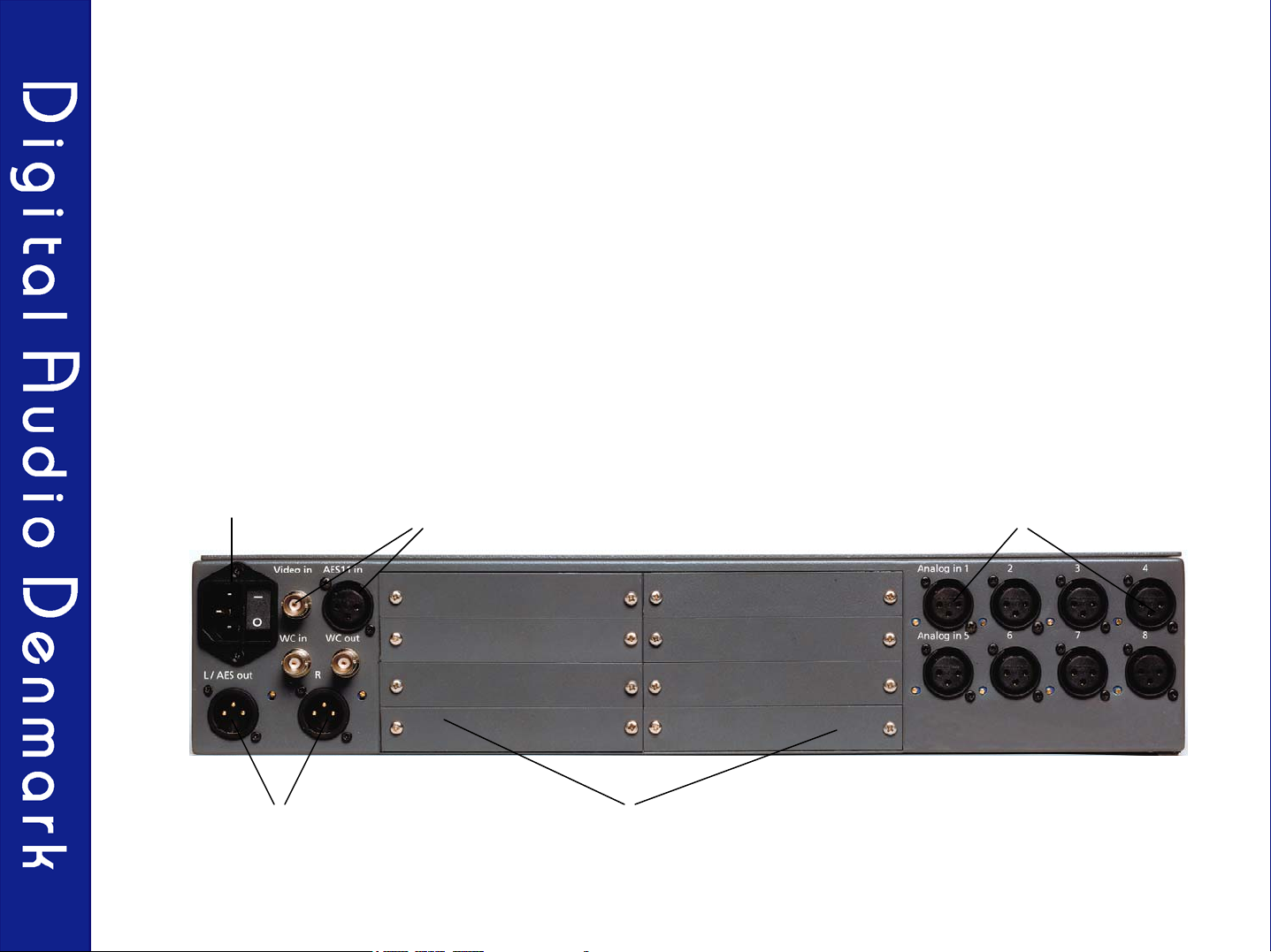
Connecting the cables
1. Place the unit on a dry surface or in a rack with plenty of space for ventilation.
2. Connect the analog cables
3. Connect the digital cables to the I/O modules and the sync cables.
4. Connect the power cord
Power cord Synchronisation Analog input 1-8
Analog stereo output or
AES
Digital and analog I/O slots for digital
I/O and analog outputs
3
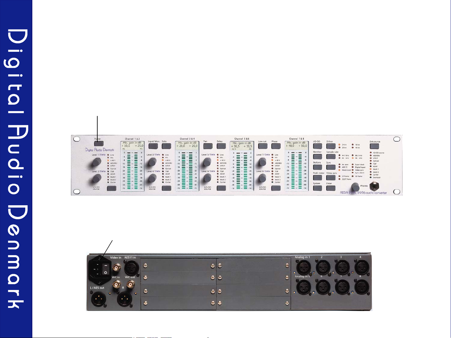
Turn on the ADDA 2408
Turn on the power button on the front panel. For turning off the power you need to press
the button for about 3 sec.
Ensure that the main power switch is on
4
Basic structure
With the DA source button you select the source for the built in 8/2 mixer and for your
analog outputs. You can choose between the input selected on the AD-D button or any of
the digital interfaces. If a valid digital signal is present the green “Carrier” LED will light up.
If you have installed a ProTools Mix 24 compatible I/O card you have to choose this
interface as Multi 1 or Multi 2.
With the AD-D source button you can choose the input (for 2 channels at a time) which
will be availably as a digital signal on all digital multi-channel
rate, dither and sync selected at the sample-rate, dither and sync buttons.
outputs with the sample-
If you choose an analog signal the converter will work as an A/D converter.
If you choose a digital signal the converter will work as a sample-rate and/or a format
converter. If the incoming digital signal is not in sync with the converter it will be detected
and the signal will be sample-rate converted.
If a valid digital signal is present the green ‘Carrier’ LED will light up.
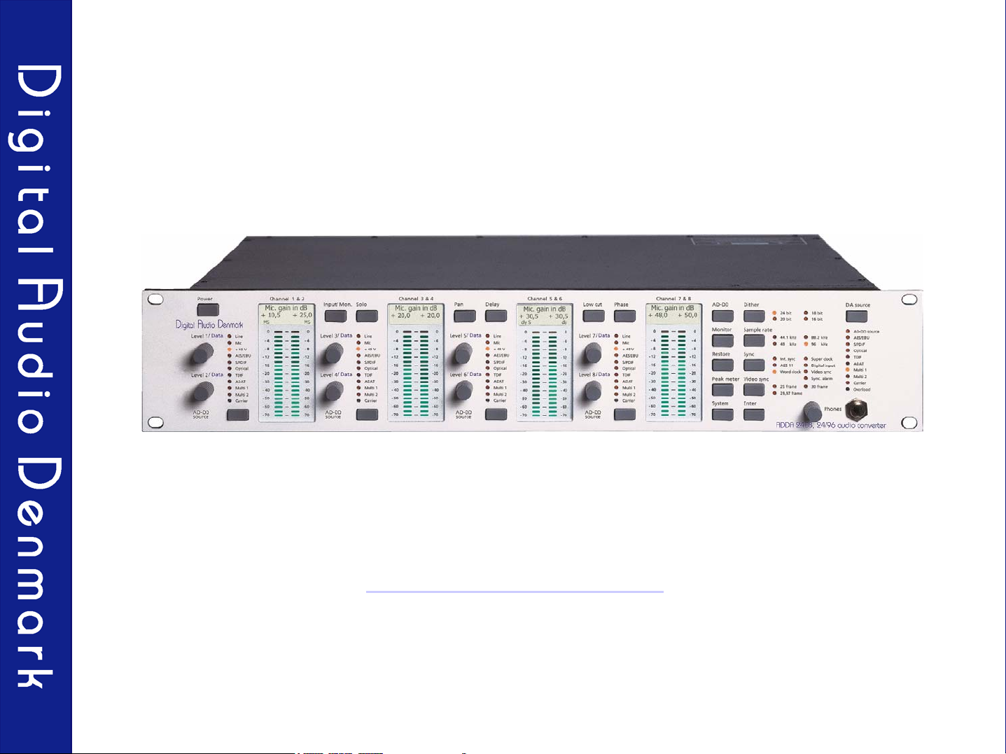
5
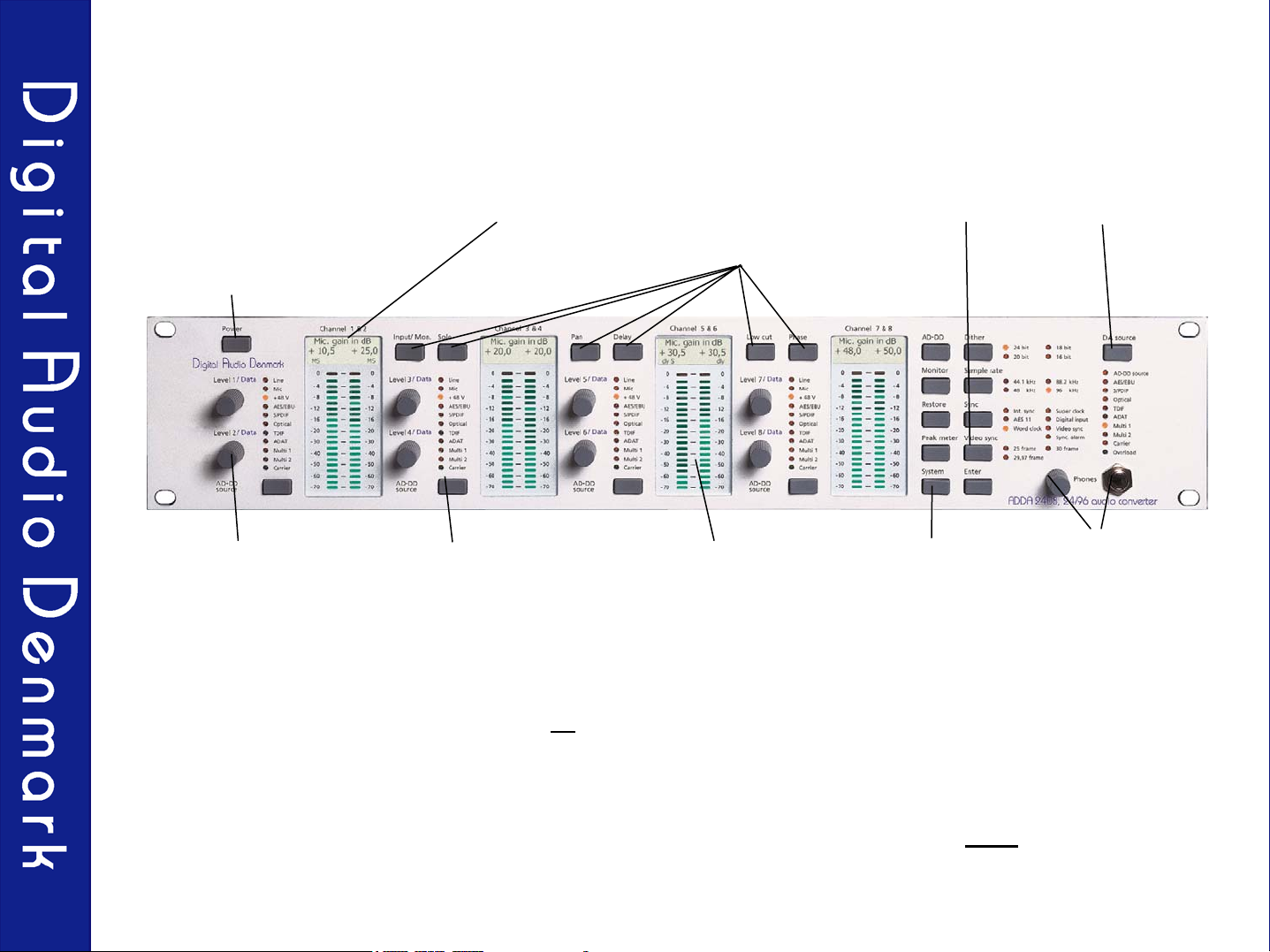
Overview
Power button with Security
locks, (the main power can
only be turned off by a
continuous 3 seconds
press on the power
button).
Level/data controls
for all 8 channels.
AD-D source button
for selection between
the analog or digital
inputs (2 channels
at the time)
LCD display for all
stereo channels.
Short cuts button for
Input/monitor, Solo, Pan,
Delay, Low cut, and
Phase inversion.
Detailed 21 LED peak
metering measuring
the digital or analog
input.
Sample-rate,
sync and dither
buttons
A/D-D/A and
Systems button
DA source
button
High quality analog
headphone amplifier.
The Level/data controls are used for all selections and adjustments. For adjustment of a
parameter related to a channel (1-8) use the corresponding Level/data controls. For adjustment
of an ‘over-all’ parameter use the Level/data controls and the LCD display for channels 7 & 8.
All primary functions are available by pressing only one button!
6

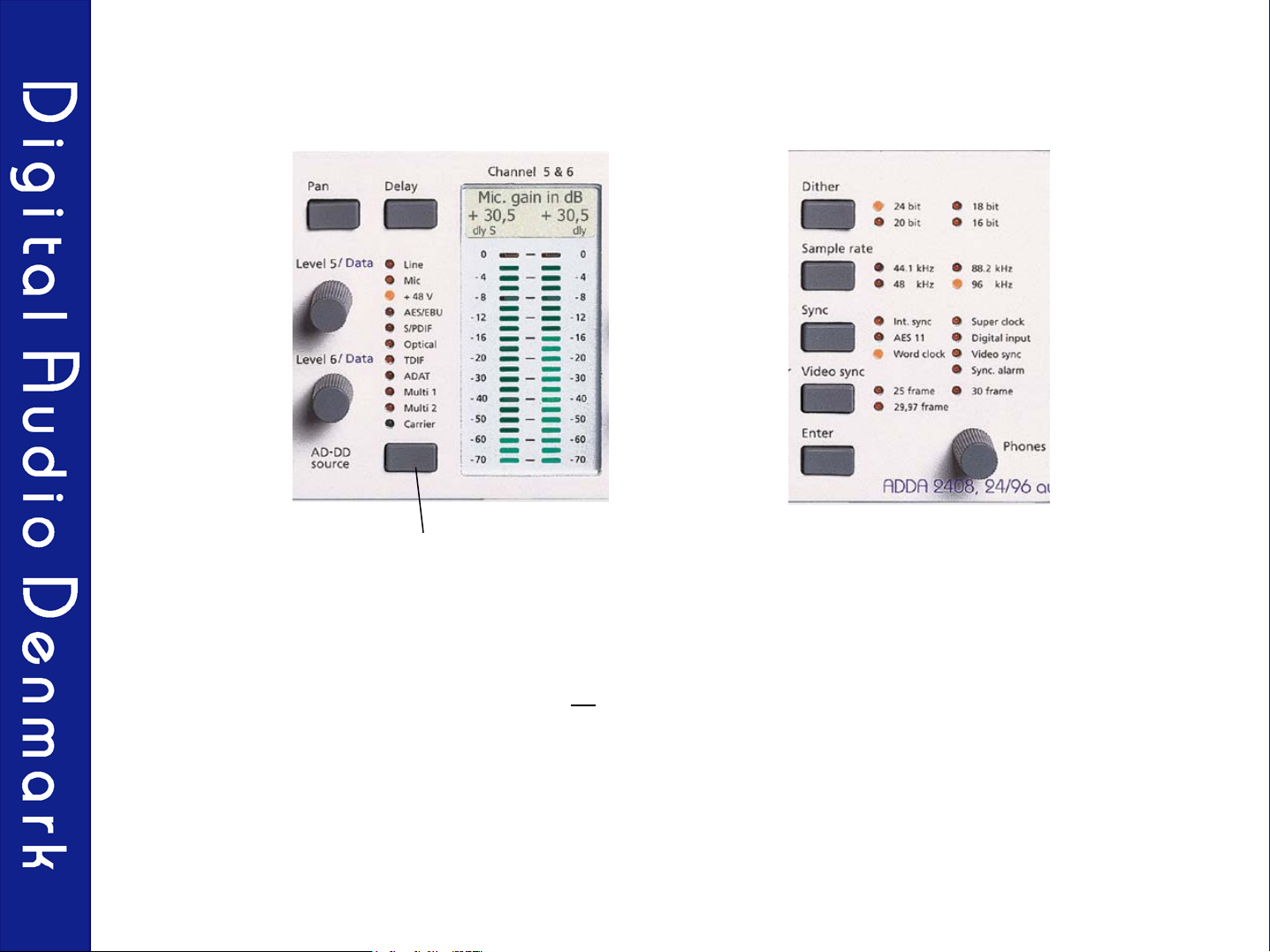
Short Cuts
Input/monitor
level
Level/data knobs for
the 8 channels
The short cut buttons provide fast access to the primary functions in the AD-DD and Monitor
menus.
AD-DD and Monitor
menu
PhaseSolo Pan Delay Low cut
The short cuts are only active when the short cut button is pressed. After releasing a short cut
button the ADDA 2408 returns to the function prior to short cut activation.
If for instance the Mic gain in dB is selected and a short cut is activated, the corresponding
function may be adjusted using the Level/Data knob for one or more channels. By releasing the
short cut button the ADDA 2408 returns to the Mic gain in dB function. It is therefore easy at all
times to identify the active functions of the ADDA 2408..
It is recommended to set the ADDA 2408 into Mic gain in dB or Monitor level mode while
recording.
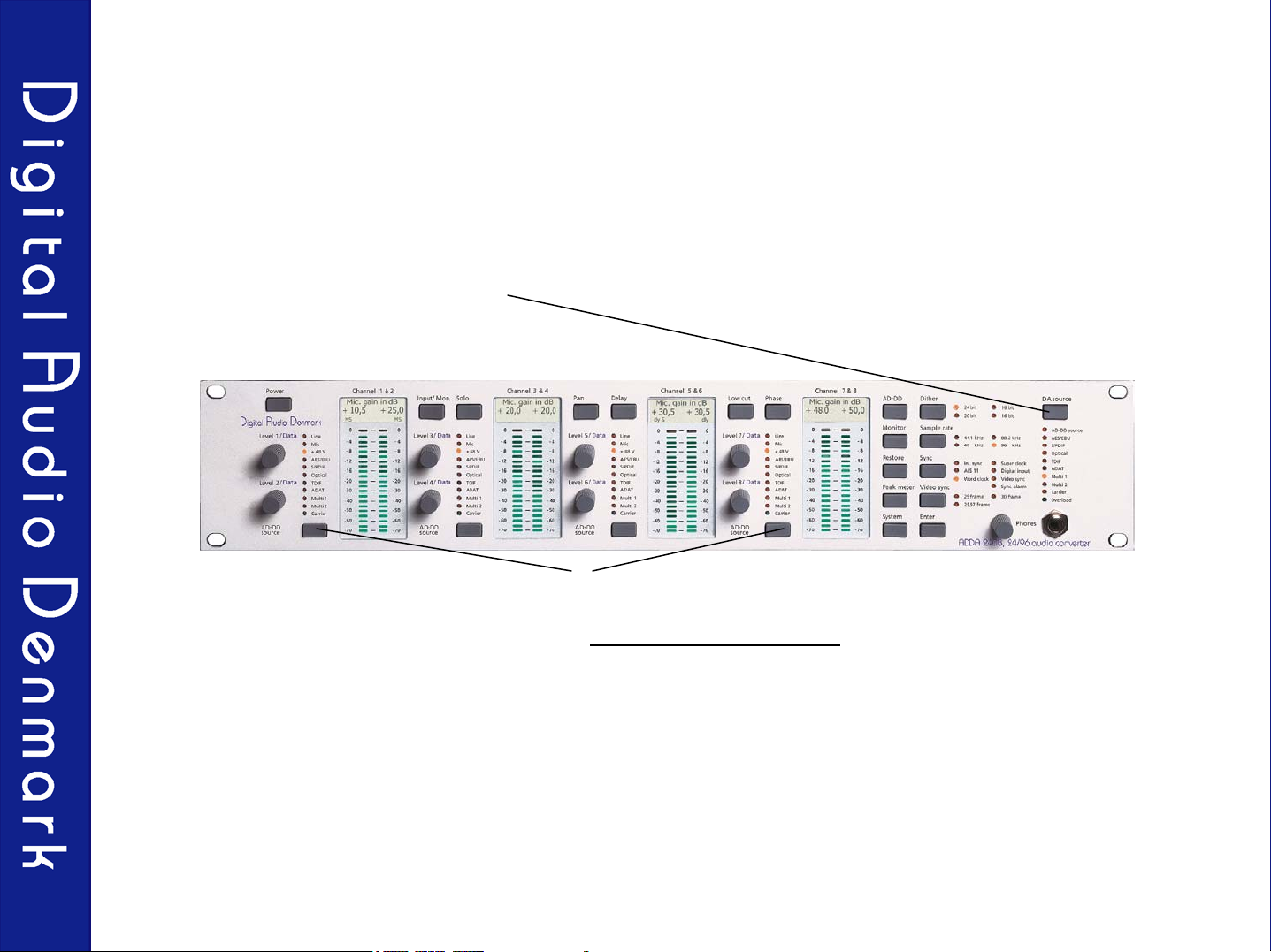
7
AD-DD Source Button
AD-D source button
With the AD-DD source button you can choose between the different analog or digital interfaces
for two channels at a time.
The selected input will be available on all
synchronization chosen at the Sample-rate, Dither and Sync buttons.
This way the unit can be either an A/D, a sample-rate, or a format converter between the digital
I/O’s mounted in the ADDA 2408.
If the selected digital input has a different sample-rate or synchronization than the sample-rate and
synchronization chosen at the Sample-rate and Sync buttons, the unit will auto-detect the
difference and use the built in sample-rate converter automatically.
digital outputs with the sample-rate, dither and
8
 Loading...