

Page 1
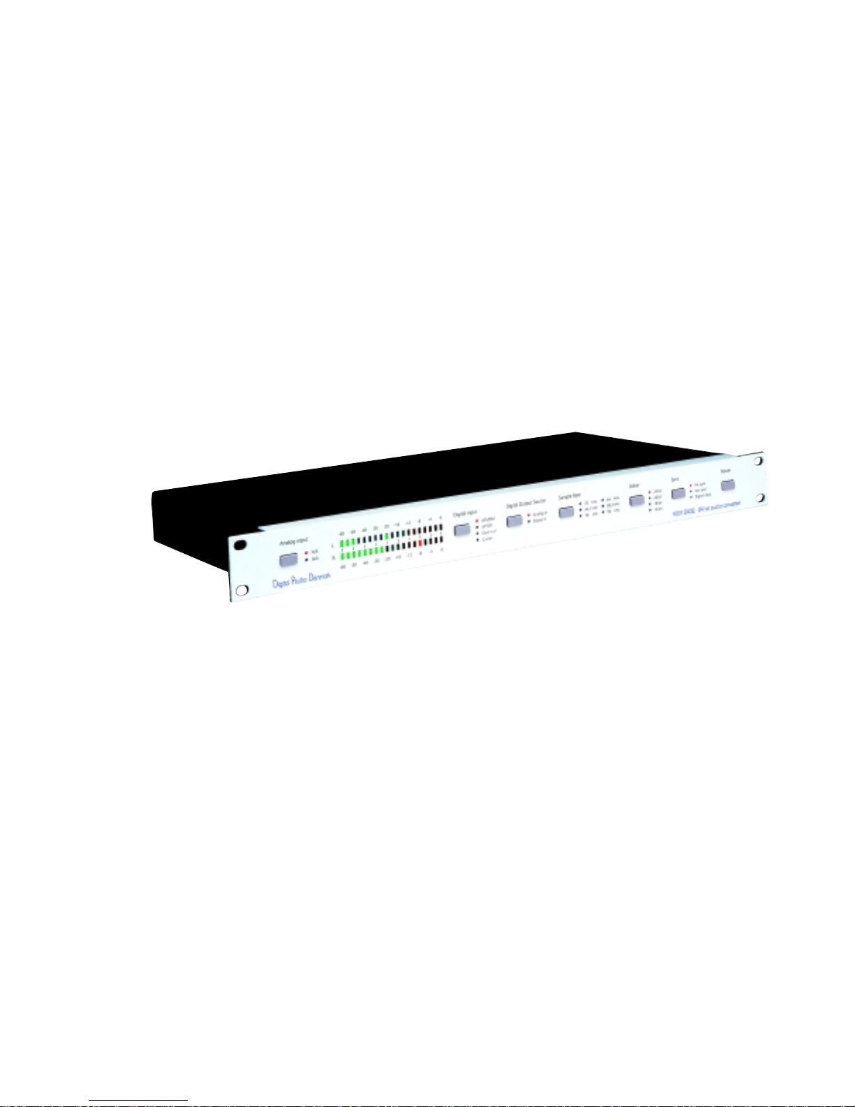
ADDA 2402
User manual
Page 2
IMPORTANT SAFETY AND INSTALLATION INSTRUCTION
SAVE THESE INSTRUCTIONS
INSTRUCTIONS PERTAINING TO RISK OF FIRE, ELECTRIC SHOCK, OR INJURY TO PERSONS
WARNING – when using electric products, basic precautions should be followed, including the following:
1. Read all of the safety and installations instructions and explanation of graphic symbols before using the product.
2. The product must be grounded. If it should malfunction or breakdown, grounding provides a path of least resistance or
electric current to reduce the risk of electric chock. This product is equipped with a power supply cord having an equipmentgrounding conductor and a grounding plug. The plug must be plugged into an appropriate outlet which is properly installed
and grounded in accordance with all local codes and ordinances.
DANGER – Improper connection of the equipment-grounding can result in a risk of electric shock. Do not modify the plug
provided with the product – if it will not fit the outlet have a proper outlet installed by a qualified electrician. Do not use an
adapter which defeats the function of the equipment-grounding conductor . If you are in doubt as to whether the product is
properly grounded, check with a qualified serviceman or electrician.
3. Do not use this product near water – for example, near a bathtub, washbowl, kitchen sink, in a wet basement, or near a
swimming pool, or the like.
4. This product should only be used with a stand or cart that is recommended by the manufacture.
5. This product, either alone or in combination with an amplifier and speakers or headphones, may be capable of producing
sound levels that could cause permanent hearing loss. Do not operate at a high volume level or at a level that is uncomfortable.
If you experience any hearing loss or ringing in the ears, you should consult an audiologist.
6. The product should be located so that its location or position does not interfere with its proper ventilation.
7. The product should be located away from heat sources such as radiators, heat registers, or other products that produce heat.
8. The product should be connected to a power supply only of the type described in the operating instructions or as marked on
the product.
9. The power-supply cord of the product should be unplugged from the outlet when left unused for a long period of time.
When unplugging the power supply, do not pull on the cord, but grasp it by the plug.
10. Care should be taken so that objects do not fall and liquids are not spilled into the enclosure through openings.
11. The product should be serviced by qualified service personnel when:
A. The power supply cord or plug has been damaged, or
B. Objects have fallen, or liquid has spilled into the product, or
C. The product has been exposed to rain, or
D. The product does not appear to be operating normally or exhibits a marked change in preformance, or
E. The product has been dropped, or the enclosure damaged.
12. Do not attempt to service the product beyond that described in the user maintenance instructions. All other servicing
should be referred to qualified service personnel.
13. WARNING - Do not place objects on the power supply cord, or place the product in a position where anyone could trip over ,
walk on, or roll anything over cords of any type. Do not allow the product to rest on or be installed over cords of any type.
Improper installations of this type create the possibility of a fire hazard and/or personal injury.
ATTENTION
: RISQUE DE CHOCK ELECTRIQUE NE PAS OUVRIR
CAUTION
RISK OF ELECTRIC SHOCK
DO NOT OPEN
CAUTION: TO REDUCE THE RISK OF ELECTRIC SHOCK
DO NOT REMOVE COVER (OR BACK).
NO USER-SERVICEABLE PARTS INSIDE.
REFER SERVICING TO QUALIFIED SERVICE PERSONNEL.
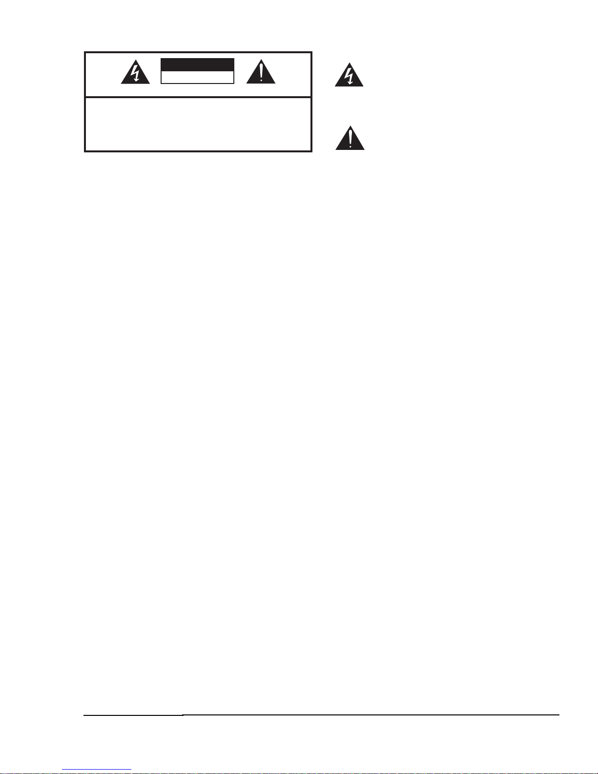
The lightning flash with arrowhead symbol,
within an equilateral triangle, is intended to
alert the user to the presence of uninsulated
"dangerous voltage" within the product's
enclosure that may be of sufficient magnitude
to constitute a risk of electric shock to persons.
The exclamation point within an equilateral
triangle is intended to alert the user to the
presence of important operating and
maintenance (servicing) instructions in the
literature accompanying the product.
Page 3

© 1999 All rights reserved. Digital Audio Denmark and ADDA 2402 are registered
Trademarks of Digital Audio Denmark a/s.
Product features and specifications are subject to change without notice .
Digital Audio Denmark a/s shall not be liable for technical or editorial errors contained herein,
nor for incidental or consequential damages resulting from the furnishing, performance or use
of this manual.
Company Address: Digital Audio Denmark. PO Box 141. DK 2630 Taastrup.
Fax. +45 43 50 49 41. E-mail: [email protected] www.digitalaudio.dk
No. 973000020 rev. 1
Page 4

Contents
5
1. INTRODUCTION 7
WELCOME 7
OVERVIEW OF ADDA 2402 7
2. INSTALLING THE ADDA 2402 9
BEFORE YOU START 9
INSTALLATION 9
Connecting the Power Cable 9
Connecting the analog audio cabels 10
Connecting the digital audio cables 10
Connecting the digital sync input 10
USE THE ADDA 2402 AS A SMALL ANALOG/DIGITAL CROSS-FIELD 10
3. OPERATION 11
FRONT PANEL CONTROLS 11
Analog Input 11
Digital Input 11
Digital Output Source 11
Sample Rate 12
Dither 12
Sync. 12
Power 12
THE PEAK METER 12
4. BLOCK DIAGRAM 13
5. SPECIFICATIONS 15
ANALOG-TO-DIGITAL CONVERSION 15
DIGITAL-TO-ANALOG CONVERSION 17
DIGITAL-TO-DIGITAL CONVERSION 19
GENEREL 21
6. References 23
7. Appendix, Distortion Effects from Aliasing in Digital Audio 25
Page 5

6
Page 6

1. Introduction
Welcome
Congratulations, and thank you for purchasing the Digital Audio Denmark ADDA2402 audio
converter. You have in your possession an extremely capable audio converter, which enables
you to perform high-end analog-to-digital, digital-to-analog and digital-to-digital conversion
of audio signals.
Overview of ADDA 2402
The ADDA2402 is a full duplex converter, which can perform independent simultaneous
analog-to-digital (A/D), and digital-to-analog (D/A) conversion between analog audio signals
and AES/EBU or S/PDIF digital audio signals. The digital interfaces comply to AES31.
The A/D converter converts an analog audio signal to a high quality digital signal with a
sample-rate of 32 kHz, 44,1 kHz 48 kHz, 64 kHz, 88,2 kHz or 96 kHz, a noise floor below
117 dB(A)2 at 44,1 Khz sampling, and a THD+N below 107 dB at 6 dBu input level.
The input level can be monitored on the Peak Programme Meter (PPM) at the front, and the
input can be selected to be either the XLR connectors or Jack connectors.
The A/D conversion is 24 bit. Depending on the conversion application the A/D converter
resolution can be reduced to 20 bit, 18 bit or 16 bit by adding psycho acoustic dither 3 to the
signal.
The bandwidth of the converted signal is equal to half the sample-rate, giving a bandwidth
from 16 to 48 kHz. The filters in the A/D converter assure that no signal is present above half
the sample-rate. This means that no aliasing distortion is introduced in the A/D converter.
Having no alias components in the digital signal eliminates the risk of generation of Alias
Intermodulation Distortion (AID)4.
The D/A converter converts a digital audio signal to a high quality analog signal having a
dynamic range better than 117 dB(A) at 44,1 Khz sampling, and a THD+N below 90 dB at
6 dBu output level.
You can chose between three digital input sources, either a professional AES/EBU signal on
XLR connectors, a consumer S/PDIF signal on Phone connectors or an optical S/PDIF signal
on a TosLink connector.
The D/A converter automatically adapts to the sample-rate of the incoming digital signal
which can be 32 kHz, 44,1 kHz 48 kHz, 64 kHz, 88,2 kHz or 96 kHz.
The ADDA 2402 can also be configured as a digital-to-digital (D/D) converter for sample-rate
conversion (SRC) of a digital input of a given sample-rate and format to a digital output of an
other sample-rate and format.
The converter can do sample-rate conversion between any of the six sample-rates from 32
kHz, 44,1 kHz 48 kHz, 64 kHz, 88,2 kHz to 96 kHz, and convert between the professional
and the consumer AES/EBU format.
ADDA 2402 has high precision internal oscillators with a stability of +/- 5 parts per million
(PPM) controlling the sample-rates. The ADDA2402 can also be synchronised to an external
reference signal complying with AES 115.
1
Please refer to section 5, references for an explanation of AES 3.
Please refer to section 3, The peak meter for a description of the input levels and the dB
notification.
3
Please refer to section 5, references for an explanation of the psycho acoustic dither.
4
Please refer to Appendix 1 for a description of AID.
5
Please refer to section 5, references for an explanation of AES 11.
7
Page 7

8
Page 8
SP/DIF
OPTICAL
SP/DIF
OPTICAL
Digital out
Analog in
L
R
AES/EBU
AES/EBU
Digital in
Analog outLR
Ext. sync
L
R
L
R
AC POWER
CONNECTOR
MAIN POWER
SWITCH
FUSE
HOLDER
EXT. SYNC
AES/EBU INPUT
OPTICAL S/P DIF
OUTPUT
S/P DIF
OUTPUT
AES/EBU
OUTPUT
OPTICAL S/P DIF
INPUT
S/P DIF
INPUT
AES/EBU
INPUT
BALANCED
ANALOG OUTPUT
SINGEL ENDET
ANALOG OUTPUT
BALANCED
ANALOG INPUT
SINGEL ENDET
ANALOG INPUT
1. Installing the ADDA 2402
Here is a quick description of all the basic things you need to cover to get started with your
ADDA 2402.
Before Y ou start
· Make sure the ADDA 2402’s voltage matches the voltage in your location. The ADDA
2402 is labelled on the AC power connector with the main voltage setting which can be
either 110-120V, 220-240V or 110-240 V at 50-60 Hz.
· Set your ADDA 2402 on a hard and dry surface or mount it onto a 19” rack, and leave
plenty of room for ventilation.
· In order to meet the EMC requirements of Directives 89/336/EEC and 93/68/EEC, and in
order the obtain the high performance possible for the ADDA 2402, you must use
correctly shielded cable of good quality for all external connections, when installing the
ADDA 2402. For the power connection a normal un-shielded cable can be used. Make
sure that the XLR, Phono and Jack connectors have conductive houses connected the
shield.
· Make sure your sound system is at a safe volume level.
Installation
This section will take you through the installation of your ADDA 2402. We will describe the
power, audio and digital cable connections, which can be accessed on the rear panel.
Connecting the Power Cable
The ADDA 2402 runs on 50-60 Hz AC voltage, and is set from the factory to, 110-120 V, 220
-240 V or 110-240 V. Excessive voltages can seriously damage the ADDA 2402, so make sure
that your AC power matches the setting of your ADDA 2402.
When you connect the power use the cable you received together with your ADDA 2402 and
plug it into a grounded outlet.
If your power source does not have the standard three-hole outlet, you should take the time to
get installed a proper grounding system. This will prevent problems with audio hum, and will
reduce the risk of a shock hazard. Furthermore it is required that the converter is grounded in
order to fullfill both the safety requirements and the EMC requirements.
9
Page 9
Connecting the analog audio cabels
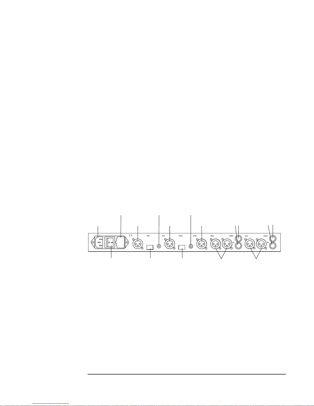
After you have turned down the level on your sound system, you can rig the ADDA 2402’s
analog audio cables. You will find two balanced XLR input connectors marked L-Analog in-R.
On The right side of the XLR input connectors you will find two Jack input connectors marked
L/R for unbalanced input. The maximum input level for giving a full scale digital signal is +
18 dBu on the balanced input and + 4 dBu on the unbalanced input.
You can use either the XLR input or the Jack input as the analog audio input source, or you can
have both inputs connected. The active input source is selected on the front panel.
You will also find two balanced XLR output connectors marked L Analog out R. On The right
side of the XLR output you will find two unbalanced Jack output connectors marked
L/R. The output level equivalent to a full scale digital input signal is + 18 dBu on the balanced
output and + 4 dBu on the unbalanced output
The ADDA 2402 will generate an output signal on both the XLR and the Jack output
simultaneous, so you can interface to your mixing board and the analog input of a keyboard
simultaneously.
Connecting the digital audio cables
On the rear panel you will find a digital input section with an optical TosLink, an S/P DIF
input connector and an AES/EBU input connector, marked Digital in, Optical, S/P DIF and
AES/EBU.
Connect one, two or all of them to the digital output on your DAT recorder, your CD player or/
and your harddisk recording system, and use the front panel to switch between the input
sources.
You will also find a Digital Output section with an Optical TosLink, an S/PDIF output
connector and an AES/EBU output connector, marked Digital out, Optical, S/P DIF and AES/
EBU.
The ADDA 2402 generates an output signal on all digital output simultaneously, so you can
interface to the digital input on your DAT, keyboard or/and your harddisk recording system,
and use your DAT, keyboard and harddisk recording system to switch between them.
Connecting the digital sync input
On the left side of the main power connection you will find the AES11 external synchronisation
input connector, marked Ext. sync. If you are using an AES11 studio master clock, you can
connect this input to your AES11 master sync. output. The ADDA 2402 will be able to
synchronise the sample-rate to the sync. signal.
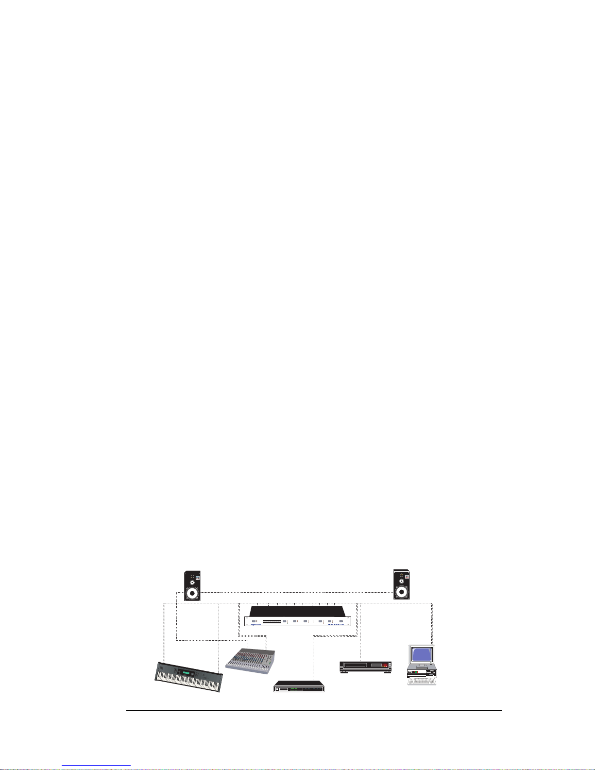
Use the ADDA 2402 as a small analog/digital cross-field
You can use your ADDA 2402 as a small analog/digital cross-field by connecting your
different studio equipment as shown below.
Mixer
HD Recorder
DAT Recorder
CD Player
Keyboard
S/P DIF IN
S/P DIF OUT
AES/EBU
IN/OUT
OPTICAL
IN/OUT
XLR
IN/OUT
JACK
IN/OUT
Analog input
Digital input
Digital Output Source
Sample Rate
Sync
XLR
Jack
Analog in
Digital in
S/P DIF
Optical
Carrier
32
44,1
48
64
88,2
96
Power
L
R
-60
-50 -40 -30 -20
-16
-12-8-4
0
-60
-50 -40 -30 -20
-16
-12-8-4
0
Int. sync
Ext. sync
Digital input
AES/EBU kHz
kHz
kHz
kHz
kHz
kHz
Dither
20 bit
18 bit
16 bit
24 bit
Rec
DAT
10
Page 10
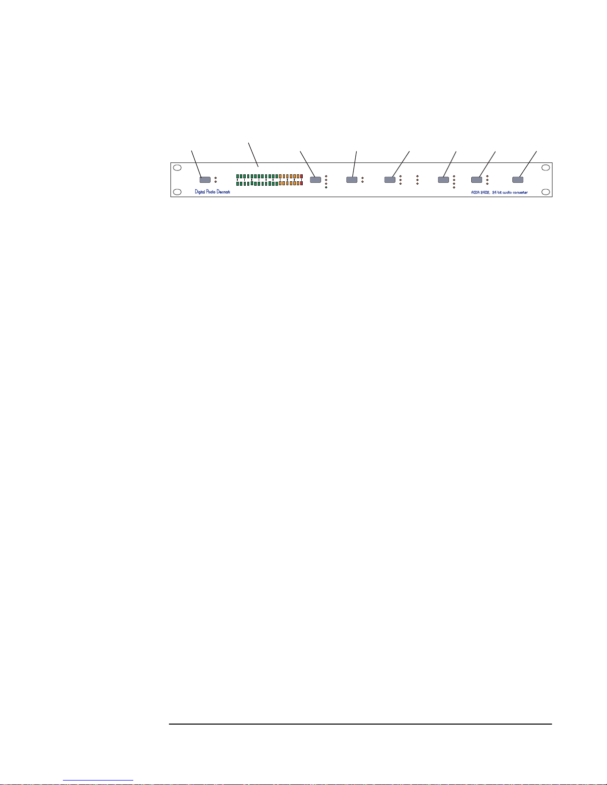
2. Operation
When you have connected the power and the audio cables, you can activate the main switch
on the rear panel in order to turn on the ADDA 2402.
Analog input
Digital input
Digital Output Source
Sample Rate
Sync.
XLR
Jack
Analog in
Digital in
S/P DIF
T DIF
Carrier
32
44,1
48
64
88,2
96
Power
L
R
-60
-50 -40 -30 -20
-16
-12-8-4
0
-60
-50 -40 -30 -20
-16
-12-8-4
0
Int. sync
Ext. sync
Digital input
AES/EBU kHz
kHz
kHz
kHz
kHz
kHz
Dither
20 bit
18 bit
16 bit
24 bit
Analog input
selector
Peakmeter
Digital input
selector
Digital output
source
Sample rate
selector
Dither
selector
Digital sync
selector
Power
switch
After start-up the ADDA 2402 has to calibrate for about 20 seconds. It is recommended to
leave the ADDA 2402 on for approximately 5 minutes in order to warm up, and then activate
the sample-rate selection or digital input source switch. This will cause the converter to
recalibrate, and improve the dynamic range in a region of 1 to 2 dB. During the start-up
calibration process the –60dB LEDs of the PPM lights up, and the Int. Sync and Ext. Sync
LED will blink slowly.
The ADDA 2402 has a non-volatile memory system enabling the converter to remember the
active settings. After a power up, the ADDA 2402 will restore the settings from before it was
powered down.
Front Panel Controls
The buttons on the front panel control the mode of operation of the ADDA 2402. All settings
are shown by light diode indicators (LEDs). Each time a button is activated the corresponding
mode will change between the possible settings.
Analog Input
On the Analog Input button you can switch between the balanced XLR input and unbalanced
Jack input. The input signal will be converted to a digital signal when the Digital Output
Source mode is set to analog in. The digital signal is available on the AES/EBU, S/PDIF and
the optical output connectors.
Digital Input
On the Digital Input Source button you can select which of the digital inputs you would like
to be active. You can choose between AES/EBU, S/PDIF and Optical (TosLink). The digital
input chosen will always be converted to an analog signal and sent to balanced and
unbalanced analog output connectors. This means the DA converter in the ADDA 2402 will
always be active, if there is a digital input signal, no matter what other mode you use for some
of the other buttons (except the power button of course).
If there is a valid digital input signal on the selected digital input, the “Carrier” LED will
light up.
Digital Output Source
On the Digital Output Source button you can choose between analog and digital input. If you
choose analog input, the ADDA 2402 will convert your analog input to a digital output. If you
choose digital input, the ADDA 2402 will work as a sample-rate converter, and convert the
digital input to the sample-rate you have choosen on the Sample Rate button.
11
Page 11

Sample Rate
On the Sample Rate button you can select the sample-rate of the A/D converter between 32
kHz, 44.1 kHz, 46 kHz, 64 kHz, 88.2 kHz and 96 kHz. When a sample-rate has been selected,
the A/D converter will take about 3 seconds to calibrate before it is ready for operation. The
sample-rate LEDs will always show the selected sample-rate. When an external
synchronisation is selected via the Ext. sync button, the sample-rate LEDs indicate the
sample-rate of the received external synchronisation signal.
Dither
On the Dither button you can select the amount of dither added to the audio signal when
sampled by the A/D or the D/D converter. The dither setting has to correspond to the bit
resolution of the digital system to which the digital output of the converter is connected. If the
audio signal is sampled in 24 bit resolution and connected to a 16 bit hard disk recording
system, the noise behaviour of the recorded signal will not be optimal, and a clicking in the
sound can occur. Therefore it is important to set a correct bit resolution.
Sync.
On the Sync. button you can select the synchronisation source for the A/D converter samplerate. The source can be Int. Sync which is the internal +/-5ppm precision oscillator. External
synchronisation, which is the AES11 reference, signal connected to the Ext. Sync. input
connector on the rear panel. Finally, the synchronisation source can be the digital input
selected via the digital input button. If no Ext. Sync or digital input source is connected to the
ADDA 2402 the source can not be selected via the Sync. button. If a selected external
synchronisation source fails, the ADDA 2402 will automatically default to Int.Sync.. If the
signal is re-established the ADDA 2402 will automatically switch to the selected source
unless the synchronisation mode has been changed.
It is possible to detect the sample-rate of an incoming digital signal. Set the digital Sync
selector in digital input mode and use the Digital Input selector to select the digital input
source you want to detect. The sample-rate LEDs will now indicate the incoming sample rate.
Please note that an incoming signal with a sample-rate of 64 kHz will be indicated as a 48
kHz signal, because 64 kHz is not defined in AES3 as a valid sample-rate (however the
converter will D-to-A convert an incoming 64 kHz digital signal correctly).
Power
On the Power button on the right side of the front panel the converter can be set to a stand-by
mode, where the power to the electronic circuits are disabled. By pressing the Power Button in
stand-by mode, the converter re-enters the operation mode, with all power restored. If the
main switch on the rear panel is switched off there will be no power on the ADDA 2402.
The Peak Meter
The ADDA 2402 is equipped with a very precise Fast Peak Programme Meter (PPM) for
monitoring the level of the analog input signal. The PPM indicates the fast peak value of the
signal with an integration time of 10ms for full scale reading according to IEC 268-10. The
meter has a hold time of 1 second for levels from –12 dBFS to 0 dBFS. Levels below -12 dBFs
has no hold function.
The peak meter reads out the fast peak value of the input signal in dB full-scale (dBFS), where
reading is relative to the full-scale value of the digital signal. This means that for the XLR
input an analog level of +18 dBu, which is 6.16Volt RMS, will give a 0dBFS reading. A red
LED indicates 0dBFS. For –20 dBFS to 0dBFS the readout resolution is 2dB. From –12 dBFS
to –2dBFS the readout is indicated by green LEDs.
12
Page 12
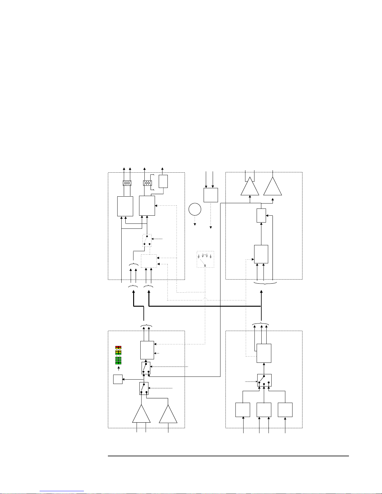
3. Block diagram
The following figure shows a block diagram of the ADDA 2402.
13
The peak meter can store the highest peak in a recording by pushing the analog input selector
rapidly twice. The diode for XLR or Jack will flash, and the highest peak will continue to
light up. To release the peak meter just press the analog input selector rapidly twice again
It is recommended to adjust the input signal to a maximum, peak value of –12dBFS. This
means that the meter normally reads out ‘green’ values. In this way a 12 dB headroom is
preserved, thus giving a nominal input level of +6dBu (1.55 V RMS). The meter will read
down to –60 dBFS, but still the A/D converter will have a dynamic range better than 116 dB
(A). With a 12 dB headroom, the noise floor will thus be below 104 dBrel(A) to the nominal
level of 6dBu (0dBrel).
24 bit
ADC
XLR
Amp
in+
in-
Amp
in
Jack
+18dBFs
Fast
Peak
data
clock
Input level L/R
+4dBFs
Analog Input Source:
-XLR input
-Jack input
Dither:
-24 bit
-20 bit
-18 bit
-16 bit
AES/EBU
Input
optical
Optical
input
AES/
EBU
AES/EBU
XLR
S/
PDIF
S/PDIF
Phono
clock
data
status
+
-
Digital Input Source:
-AES/EBU
-S/PDIF
-Optical
XLR
Jack
24 bit
DAC
Clock
data
status
de-
emphasis
Amp
Amp
out+
out-
out
data
clock
status
TOS
Link
AES/EBU
S/PDIF
S/PDIF
Optical
AES/EBU
XLR
S/PDIF
Phono
+
SRC
Option
+
-
data
clock
Analog Input Section
Analog Output Section
Digital Input Section
Fs = 32 kHz
44,1 kHz
48 kHz
64 kHz
88,2 kHz
96 kHz
Ext. sync
AES/
EBU
AES/EBU
Sync
XLR
+
-
osc
Sample Rate selection
File:adda_blok_2.vsd
Digital Master Clock
Analog Master Clock
Digital Output Source:
-Analog input
-Digital input
Digital Output Section
Digital Output Source:
-Analog input
-Digital input
Page 13

14
Page 14
Analog to Digital Audio Conversion
Cross-talk:
· Cross-talk at 997 Hz, -3 db Fs < 110 dB
Frequency response
· Fs 32kHz, 18 Hz-13,5 kHz:±0.1dB
· Fs 44,1kHz, 18 Hz-18,8 kHz:±0.1dB
· Fs 48kHz, 18 Hz-20,0 kHz:±0.1dB
· Fs 64kHz, 18 Hz-25,0 kHz:±0.1dB
· Fs 88,2kHz, 18 Hz-35,0 kHz:±0.1dB
· Fs 96kHz, 18 Hz-38,0 kHz:±0.1dB
The frequency response has a Stop-band attenuation of 117 dB at half the sampling frequency, thus eliminating high-frequency aliasing.
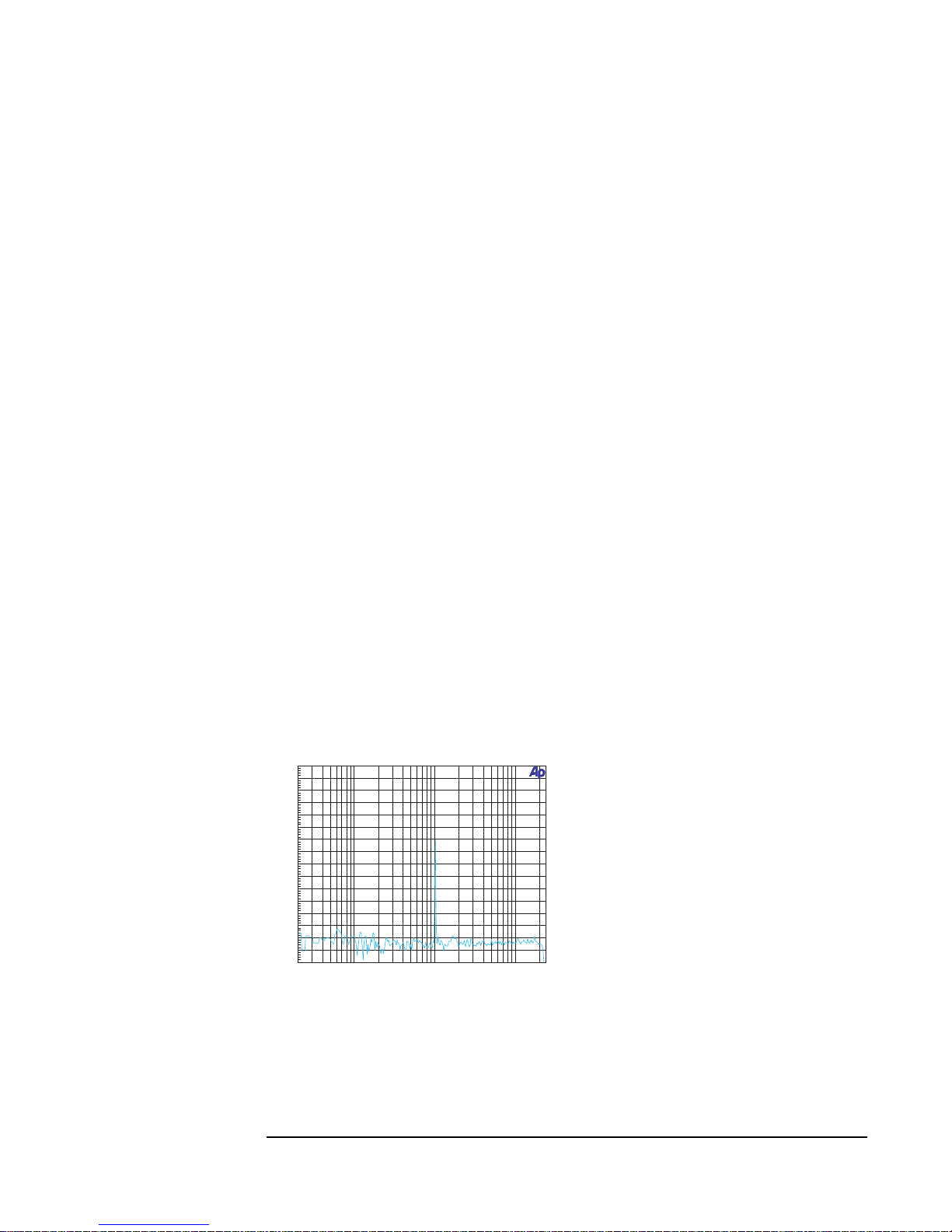
Dynamic range
The Dynamic Range is better than 117 dB (A-weighted) at 44,1 kHz sampling. The dynamic
range with a –60 dB FS input signal is better than 140 dB measured as a FFT.
Digital Audio Denmark a/s A-D Dynamic range@997 Hz
-160
+0
-150
-140
-130
-120
-110
-100
-90
-80
-70
-60
-50
-40
-30
-20
-10
d
B
F
S
20 20k50 100 200 500 1k 2k 5k 10k
Hz
4. Specifications:
15
Processing delay:
· Processing delay < 1,0 ms
Page 15
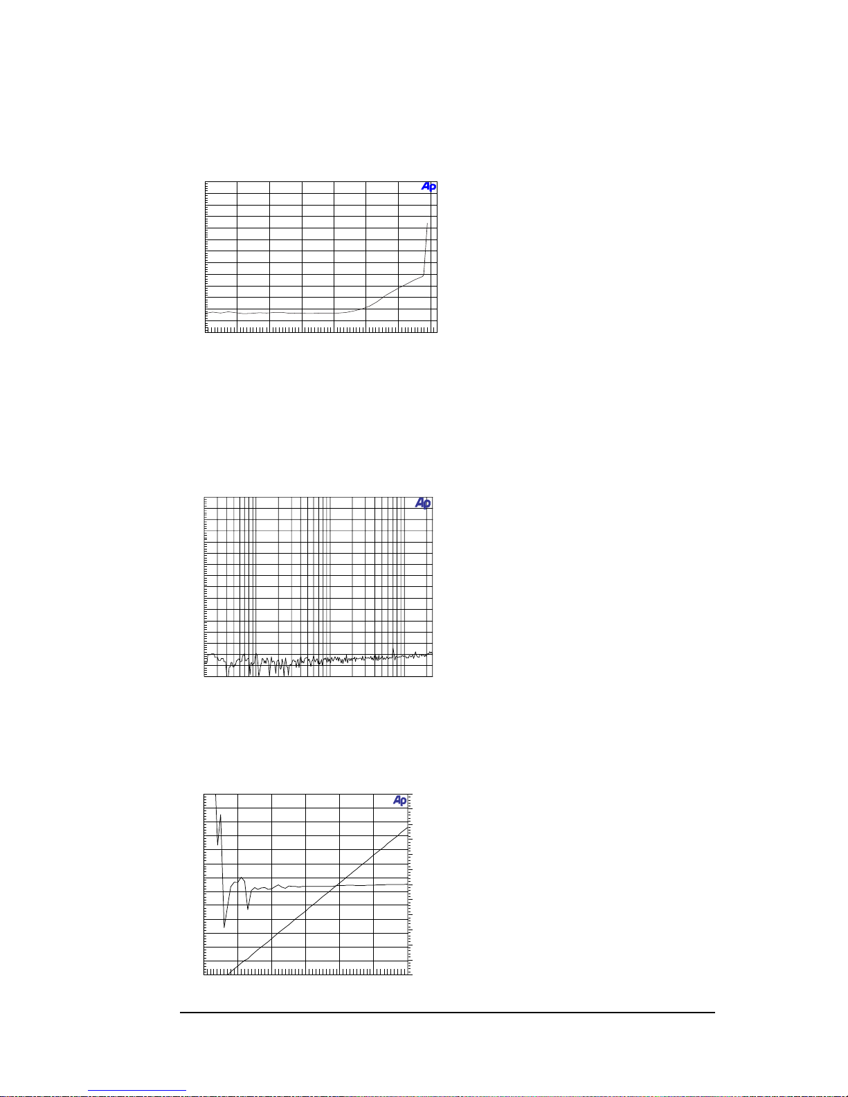
THD+Noise
The THD+N vs. input amplitude is shown in the figure below. At a nominel input level of 6
dBu, the THD+N is below – 104 dB.
Digital Audio Denmark a/s A-D: THD vs Amplitude@997 Hz
at 48 kHz sampling
-130
+0
-120
-110
-100
-90
-80
-70
-60
-50
-40
-30
-20
-10
d
B
F
S
-50 +20-40 -30 -20 -10 +0 +10
dBu
Residual noise
The residual noise floor is better than –140 dB.
Digital Audio Denmark
A-D Residual Noise
-160
+0
-150
-140
-130
-120
-110
-100
-90
-80
-70
-60
-50
-40
-30
-20
-10
d
B
F
S
20
20k
50
100
200
500
1k
2k
5k
10k
Hz
Linearity
Linearity better than +/- 0,5 dB down-to –105 dB
Digital Audio Denmark
A-D: Linearity @200Hz
-3
-2.5
-2
-1.5
-1
-0.5
+0
+0.5
+1
+1.5
+2
+2.5
d
B
F
S
-130
+0
-120
-110
-100
-90
-80
-70
-60
-50
-40
-30
-20
-10
d
B
F
S
-120+0-100
-80
-60
-40
-20
dBr
16
Page 16
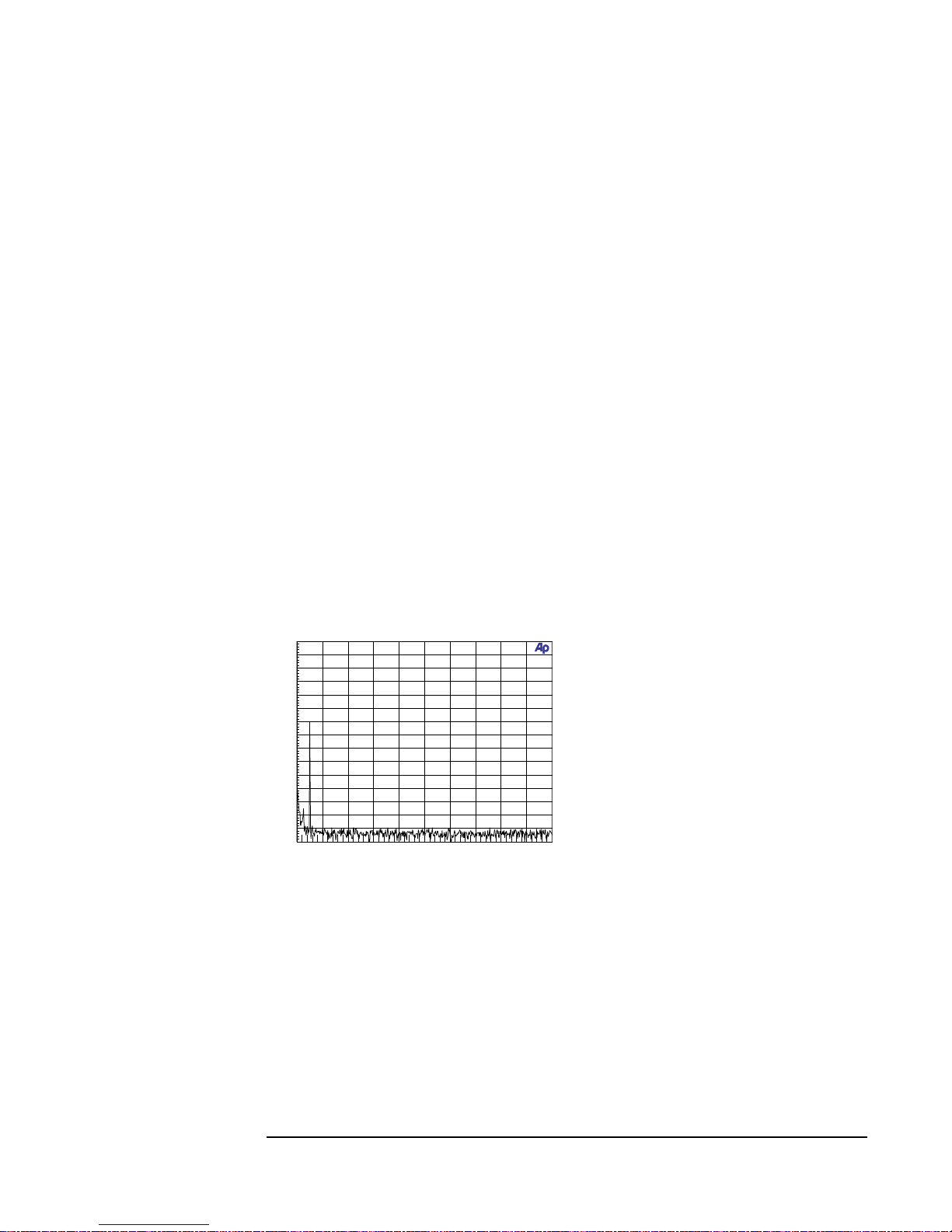
Digital to Analog Audio Conversion
Cross-talk:
· Cross-talk at 997 Hz, -3 dB Fs < 100dB
Dynamic range
The dynamic range is better than 117 dB (A-weighted) at 44,1 kHz sampling. The dynamic
range with a –60 dB FS input signal is better than 140 dB measured as a FFT.
Digital Audio Denmark
level: -60 dBFS.
-150
+0
-140
-130
-120
-110
-100
-90
-80
-70
-60
-50
-40
-30
-20
-10
d
B
u
0
20k
2k
4k
6k
8k
10k
12k
14k
16k
18k
Hz
D-A Dynamic range
17
Processing delay
· Processing delay < 0,85ms
Frequency response
· Fs 32kHz, 18 Hz–14,5 kHz:±0.1dB
· Fs 44,1kHz, 18 Hz–20,0 kHz:±0.1dB
· Fs 48kHz, 18 Hz–22,0 kHz:±0.1dB
· Fs 64kHz, 18 Hz–30,0 kHz:±0.1dB
· Fs 88,2kHz, 18 Hz–39,0 kHz:±0.1dB
· Fs 96kHz, 18 Hz–42,0 kHz:±0.1dB
Page 17
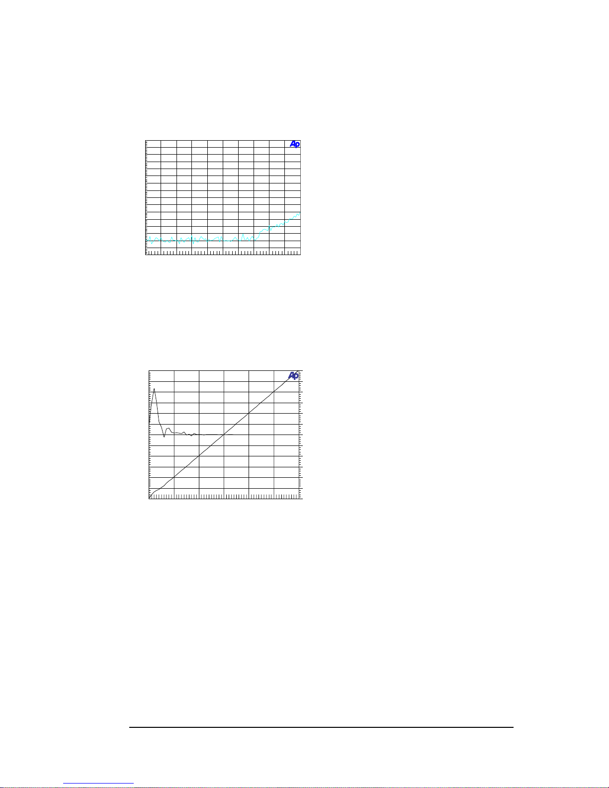
THD+Noise
THD+N output signal is measured relative to a nominal output level of 6 dBu,
THD+N is below 90 dBr.
Digital Audio Denmark a/s D-A: THD+N vs Amplitude @997 Hz
at 48 kHz sampling
-120
-40
-115
-110
-105
-100
-95
-90
-85
-80
-75
-70
-65
-60
-55
-50
-45
d
B
r
A
-50 +0-45 -40 -35 -30 -25 -20 -15 -10 -5
dBFS
Linearity
Linearity better than +/- 0,5 dB down-to –105 dB. The output level is relative to 18 dBu.
Digital Audio Denmark
D-A: Linearity @200 Hz.
-3
+3
-2.5
-2
-1.5
-1
-0.5
+0
+0.5
+1
+1.5
+2
+2.5
d
B
r
B
-120
+0
-110
-100
-90
-80
-70
-60
-50
-40
-30
-20
-10
d
B
r
A
-120+0-100
-80
-60
-40
-20
dBFS
18
Page 18
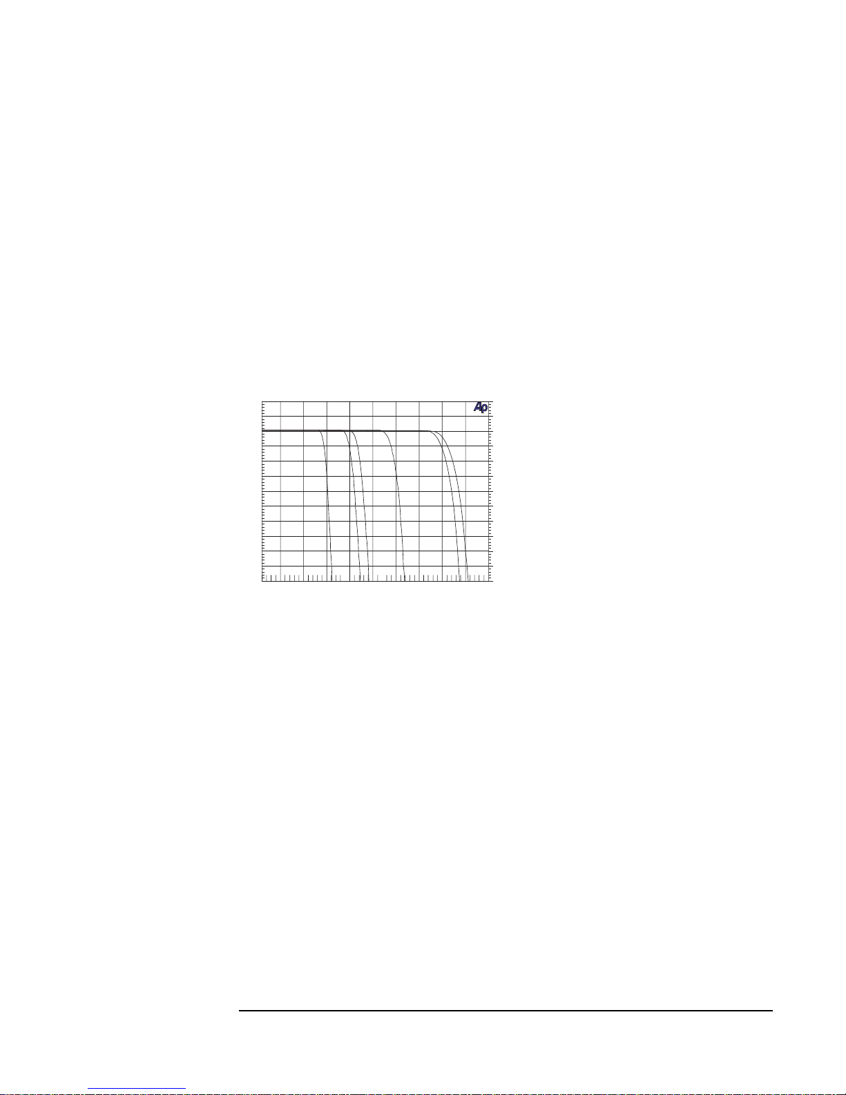
Cross-talk:
· Cross-talk at 997 Hz, 3 dB Fs < 100dB
Processing delay:
· Processing delay 2,0 ms
Frequency response
44,1 to 48 kHz 18 Hz-19,0 kHz
44,1 to 96 kHz 18 Hz-21,0 kHz
Digital to Digital Audio Conversion
19
Dynamic range
When measured A-weighted the dynamic range is better than 112 dB.
Linearity
Linearity better than +/- 0,5 dB down-to –110 dB.
Insertion gain:
At sample-rates from
32 to 48kHz: -1,0 dB
64 to 96kHz: -1,5 dB
Digital Audio Denmark
A-D D-A Freqquency Response
-100
+20
-90
-80
-70
-60
-50
-40
-30
-20
-10
+0
+10
d
B
u
5k 50k10k 15k 20k 25k 30k 35k 40k 45k
Hz
Page 19

20
Page 20

General specifications
DIGITAL INPUTS AND OUTPUTS
Connectors: XLR, RCA Phono, Optical
Formats: AES/EBU, S/PDIF
Sample Rates: 32 to 96 Khz
Ext. Sync: XLR, 32 to 96 kHz
AES/EBU: Acc. to AES3
S/PDIF: Acc. to IEC 958
Ext. Sync input Acc. to AES11
Digital audio signal is available on all three digital outputs simultaneously.
ANALOG INPUTS
Connectors: XLR (pin 2 hot, pin 3 cold, pin 1 ground), Jack
Impedance (Balanced): > 5 k Ohm
Impedance (Un-balanced): > 20 k Ohm
Max. Input Level (Balanced) +18 dBu
Max. Input Level (Un-balanced) + 4 dBu
ANALOG OUTPUTS
Connectors: XLR (pin 2 hot, pin 3 cold, pin 1 ground, Jack
Impedance (Balanced): < 40 Ohm
Impedance (Un-balanced): < 20 Ohm
Max. Output Level (Balanced): +18 dBu
Max. Output Level (Un-balanced): + 4 dBu
GENERAL
EMC complies with: EN 50082, and EN 500022
Operating Temperature: +5 to 45° C
Dimensions (w,h,d): 19", 1U, 275 mm
Weight: 3,3 kg
Mains Voltage: 110 - 120 VAC or 220 - 240 VAC
Power Consumption: 10 Watts
Due to our policy of continous improvement of our products, Digital Audio Denmark reserves
the right to make feature and specifications changes without notice.
21
Page 21

22
Page 22

23
AES3 AES3-1992: “AES Recommended Practice for Digital Audio Engineering
– Serial transmission for two-channel linearly represented digital audio data”
Published by Audio Engineering Society, Inc.
AES3 is a specification of the AES/EBU digital audio format. AES3 specifies
the frame format for the audio data in both professional and consumer mode, as
well as the electrical interface for the professional balanced XLR connection.
AES3 is however primarily a professional standard. The detailed specification
for the consumer interface is IEC 60958.
IEC958 IEC 60958 1989: “Digital Audio Interface”. Published by the International
Electrotechnical Commission.
IEC958 is a specification of the consumer AES/EBU digital audio format also
referred to as S/PDIF. IEC958 specifies the frame format for the audio data in
consumer mode, as well as the electrical interface for the unbalanced data
connection.
AES11 AE11-1991: “AES Recommended Practice for Digital Audio Engineering –
Synchronization of Digital Audio Equipment in Studio Operations”. Published
by Audio Engineering Society, Inc.
AES11 is a recommendation for synchronization of digital audio signals.
Recommendations are made concerning the accuracy of sample clocks as
embodied in the digital interface signal, and concerning the use of this as a
convenient reference signal.
EN50082 EN 50082-1: “Electromagnetic compatibility – generic immunity standard,
part 2: Residential, commercial and light industry”. Published by CENELEC
1992. Note that the standard also covers EN 50081-1 (part 1).
EN 50082-1 is the standard specifying the requirements for CE compliance
concerning Immunity following the EEC provisions of directives 92/31/EEC.
EN500022 EN 500022-1: “Limits and methods of measurement of radio interference
characteristics of immunity” Published by CENELEC 1987.
EN 500022-1 is the standard specifying the requirements for CE compliance
concerning Emission following the EEC provisions of directives 89/336/EEC.
IEC 268-10 IEC 60268-10: edition 2.0 “Sound system equipment – part 10. Peak programme
level meters” Published by the International Electrotechnical Commission
1991-03.
EN 60268-10 is the standard specifying the requirements of audio-frequency
peak programme level meters, for use in equipment for broadcasting, sound
reinforcement, sound recording, and household entertainment.
DITHER The dither of the ADDA 2402 is implemented by using a psychoacoustic noise
shaping filter for truncating the 24 bit audio word to 16, 18 or 20 bits, while the
24 bit sound quality is preserved. A detailed description of the dither algorithm
can be found in the AES paper: “Psychoacoustically Optimal Noise Shaping” by
Robert A. Wannamaker, Journal of the Audio Engineering Society, Vol 40,
No 7/8, 1992 July/August.
7. References
Page 23

Distortion Effects from Aliasing in Digital Audio
Mikael Vest and Peter Scheelke
Digital Audio Denmark
www.digitalaudio.dk
ABSTRACT
When converting audio between the analog and digital audio domains, the well-known effects from alias signals have
to be taken into consideration. Generally, audio converters do not have adequate filtering to eliminate this kind of
spectral distortion. During recent works it has been concluded that the sound quality of digital recordings can be drastically
improved when applying efficient stop-band filtering.
INTRODUCTION
When converting an analog signal to a digital
signal, the analog signal is sampled with a frequency
of twice the bandwidth that is required for the digital
representation. To get an optimal sampling, the
bandwidth of the analog signal must not exceed half
the sampling frequency , also referred to as the Nyquist
frequency (NF). If frequency contents are present above
the NF, a mirror of the frequencies is generated at
frequencies symmetrical to the NF and new frequencies
are thus generated with no harmonic relationship to
the tonal contents of the original signal. This
phenomenon is referred to as aliasing distortion. If the
distortion is only present at high frequencies, it is not
likely that it can be heard, and therefore it will not
degrade the signal quality. However, when the digital
signal has to be reproduced using D/A coverters,
amplifiers and indeed analog transducers such as
loudspeakers will introduce intermodulation distortion
(IMD) to the signal. IMD means that the frequencies
of the signal mix together and generate new
frequencies, which can be audiable if the distortion
exceeds certain levels. The problem is now that when
new a-tonal frequencies are added to the signal due to
aliasing distortion, such signals will mix very badly
with the rest of the program and thus be audiable.
The important fact of this problem is that
distortion happens when the signal has both aliasing
distortion and IMD above a certain level. Of course, it
depends on the quality of the sampling and the quality
of the reproduction equipment, and in particular the
loudspeakers. This effect is referred to as Aliasing
Intermodulation Distortion (AID).
Over the years discussions and papers on sound
quality of digital recorded material have been many.
However, at the 106th AES Convention in Munich a new
thesis was presented by Mr. Richard Black [1] stating
the problems of this combined distortion phenomenon.
-100
-90
-80
-70
-60
-50
-40
-30
-20
-10
+0
dB
5k 50k10k 15k 20k 25k 30k 35k 40k 45k
Hz
-110
-120
44.1 kHz sample rate
48 kHz sample rate
Nyquist Frequency
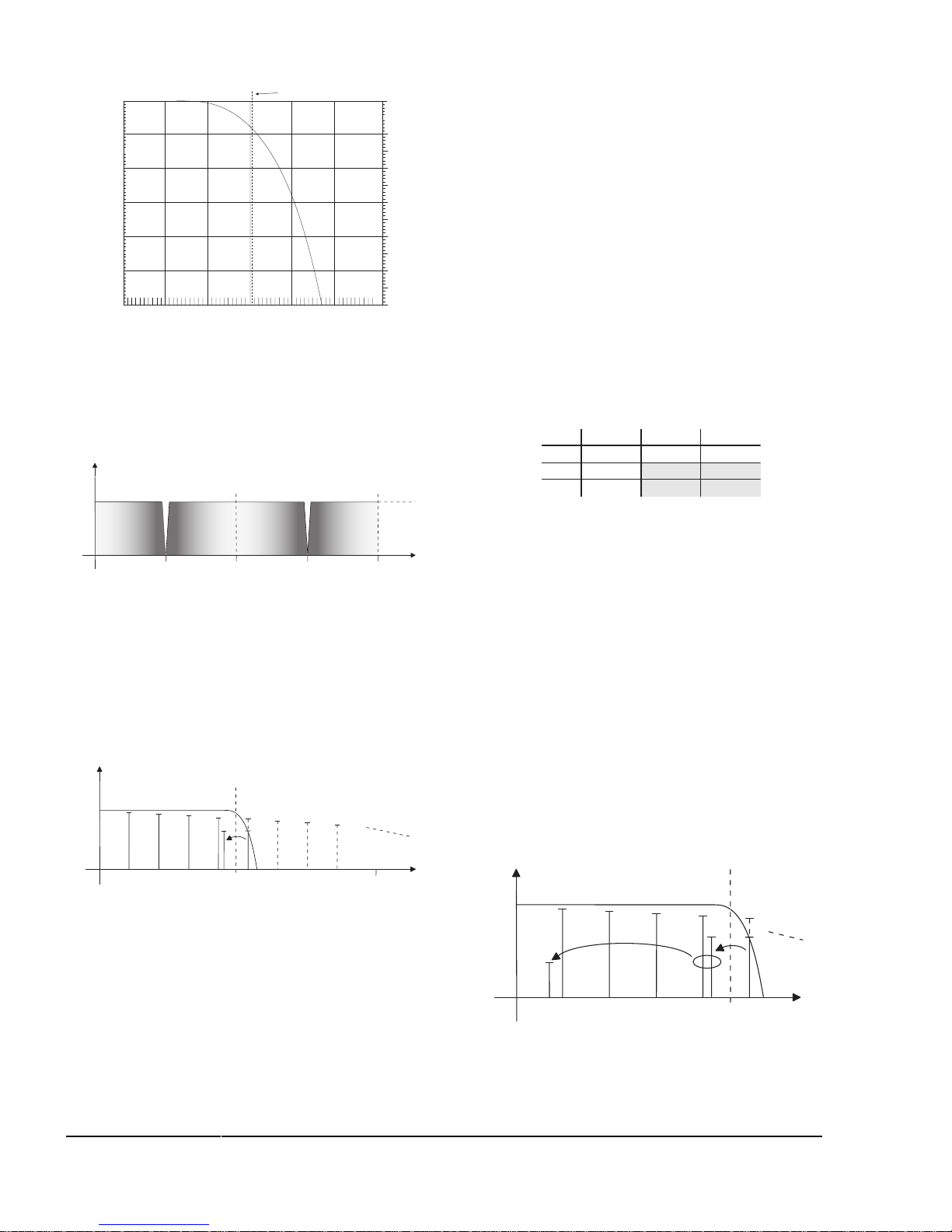
In the case of FS = 44,1 kHz, the stop-band will
only be effective at 24,26 kHz, and the attenuation at
the NF is approx. 8.5 dB. In Figure 2 a close-up of the
transition band frequency response is shown.
Figure 1, Frequency response of 0.45/0.55xFS filter
Today high quality audio A/D converters are
typically based on the delta-sigma conversion
principle with 64/128 times over sampling and
internal digital filtering. According to the
manufacturers of the converter chipset, this removes
the need for an external anti-alias filter. However the
filters normally implemented are so called 0.45/0.55
times the sample frequency (FS) filters. This means
that the pass band goes to 0.45xFS, and the stop-band
starts from 0.55xFS. In Figure 1 the frequency
response is shown with 44.1 kHz and 48 kHz sample
frequency .
This paper has the purpose of explaining the
basis of this distortion type, which he had recently
identified.
25
Figure 1, Frequency response of 0.45/0.55xFS filter
Page 24
44.1 kHz sample rate
Nyquist Frequency
-50
-40
-30
-20
-10
+0
dB
19k 25k24k
Hz
-60
20k 21k 22k 23k
According to the classic theory on sampling of
analog signals, the spectrum of the signal will be
mirrored round the NF and repeated for each multiplum
of the NF, as shown in Figure 3.
fs/2 fs
2/3 fs
2fs
f/Hz
A/dB
If signal contents are available in the signal above
the NF a mirror of the signal will fold down below the
NF as an alias signal, and thus generate aliasing
distortion. If a broadband signal is sampled with a 0.45/
0.55 anti-alias filter, the spectrum can act as shown in
the example in Figure 4.
fs/2
fs
f/Hz
A/dB
f0
f1
f2
f3
f4
f5
Aliasing distortion
The example shows a signal with a fundamental
frequency of f0 and a number of harmonics. The 4
th
harmonic is just above the NF , but still in the transition
band of the anti-alias filter of the A/D converter.
INTERMODULATION DISTORTION
Intermodulation distortion is a type of distortion
where non-linearities in the signal path generate
modulation between all the frequency components of
the signal. The primary source for IM distortion in the
audio signal path is the loudspeaker. This is due to the
non-linear behaviour of the speaker cone, which of course
depends on the loudspeaker type and quality.
Modulation means that new frequencies fim are
generated from all positive combinations of two existing
frequencies.
fim = | ± f1 ± f2 |
If two frequencies are denominated f1 and f2, where
f2 > f1, and assuming f2 < 2f1, the modulation frequencies
generated are as shown in Table 1.
IM distortion will appear up to a very high order,
but third order IM distortion is the highest order that
has any significance in this application. The magnitude
of the modulation products is reduced when the
modulation order rises. The non-shaded areas in the table
are the modulation products with the highest relevance.
IM distortion will generate a-harmonic signals when
aliasing distortion is present, since the alias signal will
modulate with the harmonics of the original signal.
Depending on the frequency contents of the signal
spectrum, some modulation frequencies will be more
audible than others. If an IM frequency is near the
fundamental frequency for the tonal spectrum, the effects
will be quite annoying, unless the IM frequency is within
the masking area, in which case it will not be heard. An
example of IM distortion is shown in Figure 5.
fs/2
f/kHz
A/dB
f0 4,5
f2 13,5
f3 18,0
f4 22,5
Aliasing distortion
f1 9,0
f4’ 21,6
f
4’ - f3
f4’ - f3 = 3,6
IM distortion
Figure 5, IM distortion example
Figure 2, Transition band of 0.45/0.55xFS filter
Figure 3, Spectrum of a sampled signal
Figure 4, Aliasing distortion example
When the signal is sampled with an A/D
converter having an anti-alias filter, with stop-band
attenuation at the NF, no aliasing distortion appears.
Table 1, IM frequencies
f
1
f
2
2f
1
3f
1
2f
2
3f
2
f2 - f
1
2f1 - f
2
3f1 - f
2
2f2 - 2f
1
2f2 - 2f
1
3f2 - 2f
1
3f2 - f
1
3f2 - 2f
1
3f2 - 3f
1
26
Page 25

In this case the 4th overtone of a fundamental tone
of 4.5 kHz will generate aliasing distortion at 21.6 kHz.
This frequency will modulate with the other tones in
the signal spectrum, and first order modulation with
the 3rd overtone will then generate a modulation
frequency of 3.6 kHz, which is likely to be audible and
make interference with the original signal. IM
distortion coming from modulation between the
harmonics of the signal will not generate a-harmonic
distortion signals, since the IM products will have
frequencies equal to the harmonic of the signal, and
will therefore not be audible.
DVD audio
Recently the new sampling 96 kHz format has been
defined. This format is meant to be used in the music
production environments, and as the DVD linear audio
format. Generally, there is an acceptance that this
higher sample-rate gives a better sound quality due to
the extended signal bandwidth from 48 kHz to 96 kHz.
However, sampling with 96 kHz having 0.45/0.55
filters – which is currently the case for most converters
– the aliasing distortion will move up in a frequency
area where the IM distortion has very little effect since
the harmonic contents of audio signals are insignificant
above 40 kHz. An interesting test is to compare the 96
kHz sampled signals with the 44,1 kHz sampled signals
having NF stop-band filtering. At 96 kHz sampling
the ultra-sonic harmonics will be present in the signal
giving a better quality than when sampled with 44.1/
48 kHz even with a NF stop-band filter applied.
However the primary issue when considering the
different sample-rates for high quality sampling is to
avoid AID, more than having a higher sample-rate.
SUMMARY
When converting audio from the analog to the
digital domain, care has to be taken that stop-band
filtering is applied in order to avoid aliasing distortion
in the digital audio signal. Once the signal is converted
to digital, the aliasing distortion products can not be
removed with-out reducing the bandwidth accordingly.
The aliasing distortion will, when the signal is
reproduced on a set of loudspeakers having some IM
distortion, generate AID. Of course good loudspeakers
have lower distortion, but most hi-fi speakers will have
IM distortion thus giving audible AID.
The only way to eliminate the problem with AID is
to apply stop-band filtering on the A/D conversion. If
this is not done AID will cause different problems
depending on the application for the sampled digital
audio signal.
When using 44.1/32 kHz sample-rates, the NF is
close to/within the audible frequency band. This is a
problem for the Compact Disc (CD). Since CDs are
mastered in 44.1 kHz AID is a problem, if the A/D
converters are used without proper filters. If recording
is done with 48 kHz sampling, the Aliasing distortion
will be at frequencies above 20 kHz. This will be a
problem when working with the audio signals in the
sound studio, where the monitored signals will have
AID.
If digital sample-rate conversion is used to generate
the 44.1 kHz master version from 48 kHz source
material, AID will not occur since the alias products
are filtered by the sample rate converter alias filter
assuming of course that a good quality sample-rate
converter is used.
Not many A/D converters are available with NF
stop-band filtering. As mentioned in the abstract, the
majority of converters have 0.45/0.55 anti-alias filters,
which will result in AID. One converter chip is however
available today with NF stop-band filtering, and that
is the CS5397 from Crystal Semiconductors.
This topic of AID and the influence of sampling
bandwidth on the sound quality is something that needs
to be investigated further, since to our knowledge
documented test results are not available. This is
however a subject in which Digital Audio Denmark
will conduct more research in the future.
Digital Audio Denmark A/D converters
The ADDA 2402 A/D, D/A and D/D converter from
Digital Audio Denmark has implemented NF stop-band
filtering for eliminating the risk of AID. This means
that digital recordings can be made without aliasing
distortion. However, a trade-off has to be made
concerning the bandwidth of the sampled signal. When
sampling with 44.1 kHz the transition band starts at
18.1 kHz, and the attenuation at 20 kHz is 12 dB. This
means that the signal 3 dB bandwidth is reduced to
19.3 kHz.
References
[1] R. Blake: “Anti-alias filters: the invisible distortion
mechanism in digital audio”. Preprint 4966, 106
th
AES Convention, Munich 1999.
27
 Loading...