

Page 1
Page 2
1
2
3
5
7
8
9
10
11
11
12
11
13
5
7
8
9
10
11
11
12
11
13
Page 3
7
11
13
5
5
7
8
9
10
11
11
12
11
13
Page 4
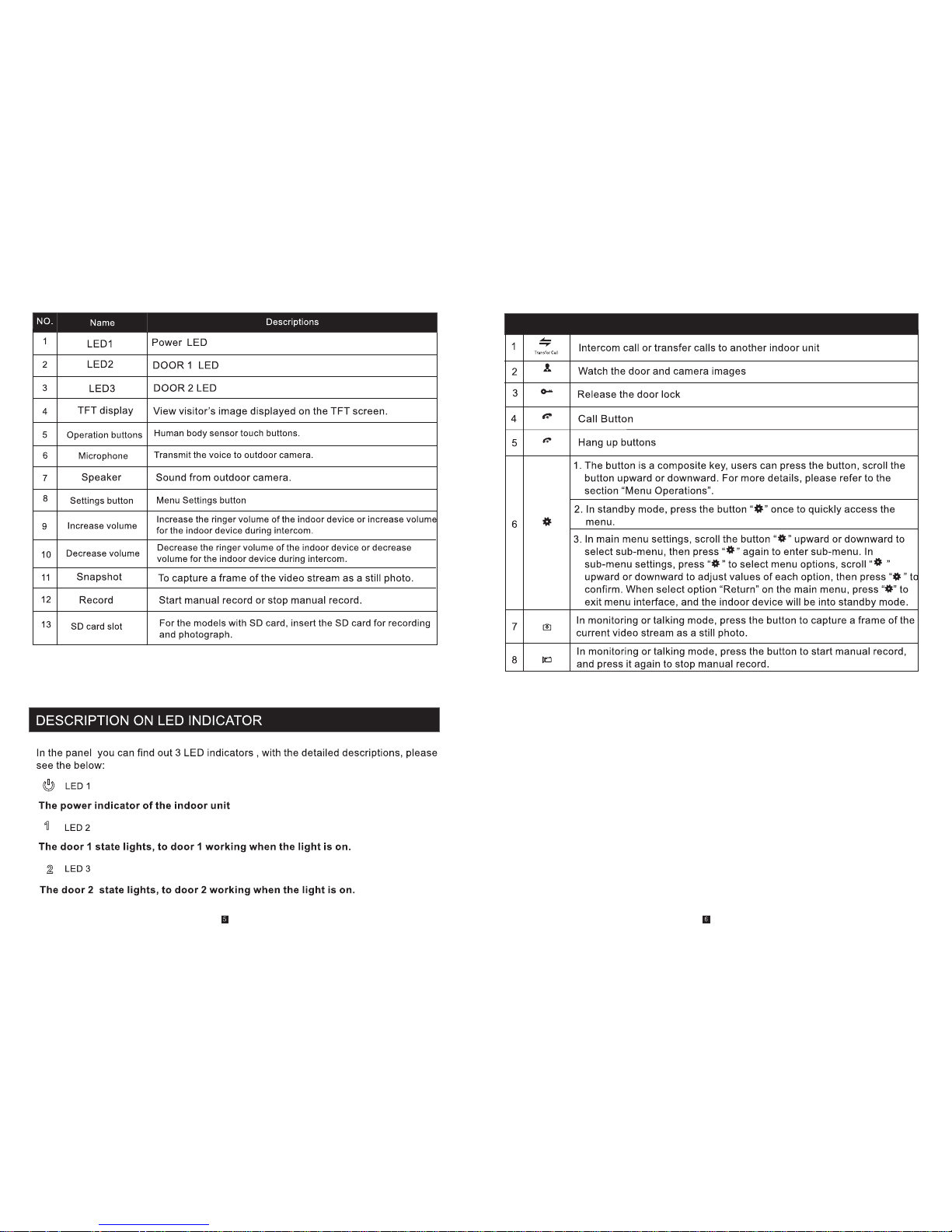
DESCRIPTION ON SYMBOL
Hang up
Unlock
Monitoring
Setting
Talk
Page 5
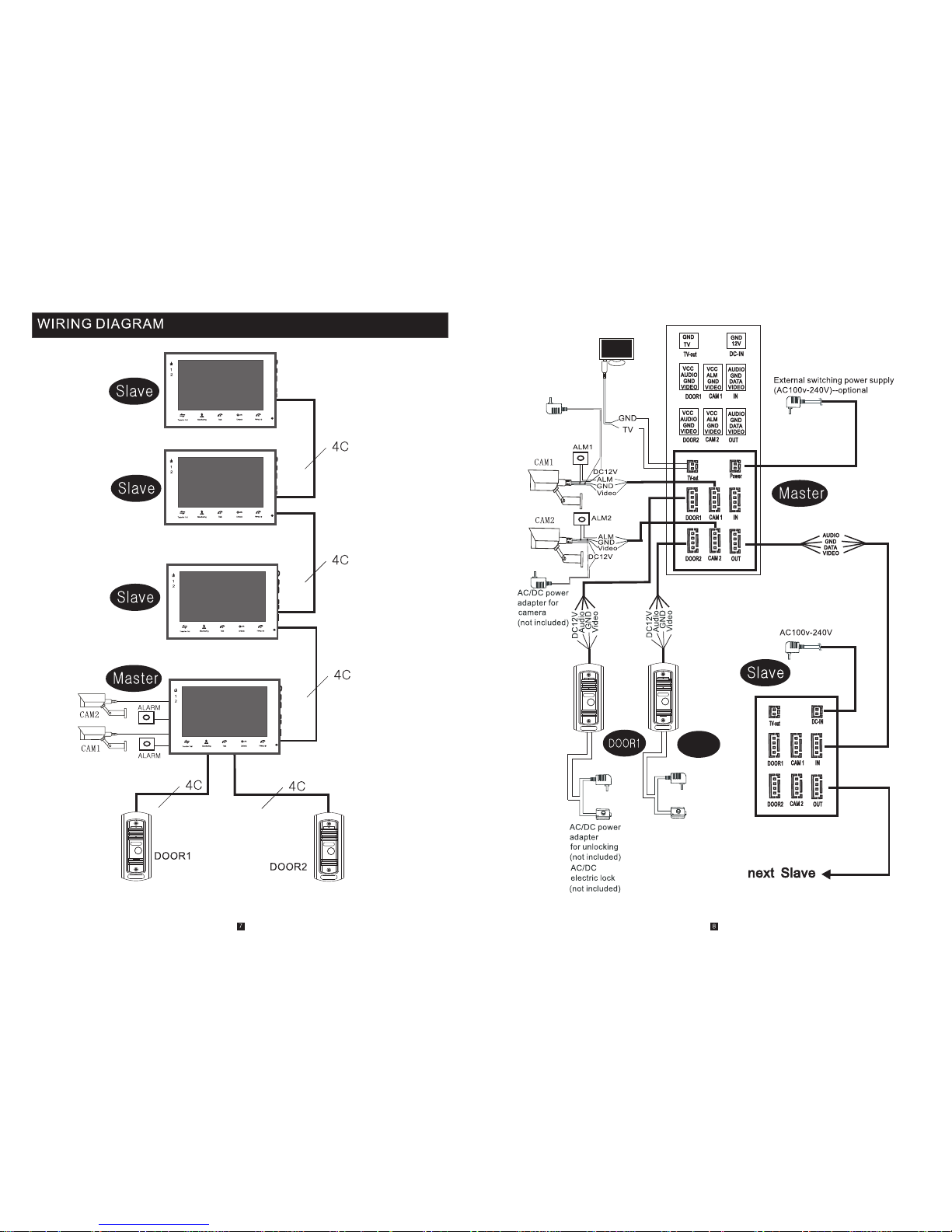
AC/DC p ower
adapt er
for unl ockin g
(not in clude d)
AC/DC
elect ric loc k
(not in clude d)
DOO R2
AC/DC p ower
adapt er for
camer a
(not in clude d)
Page 6
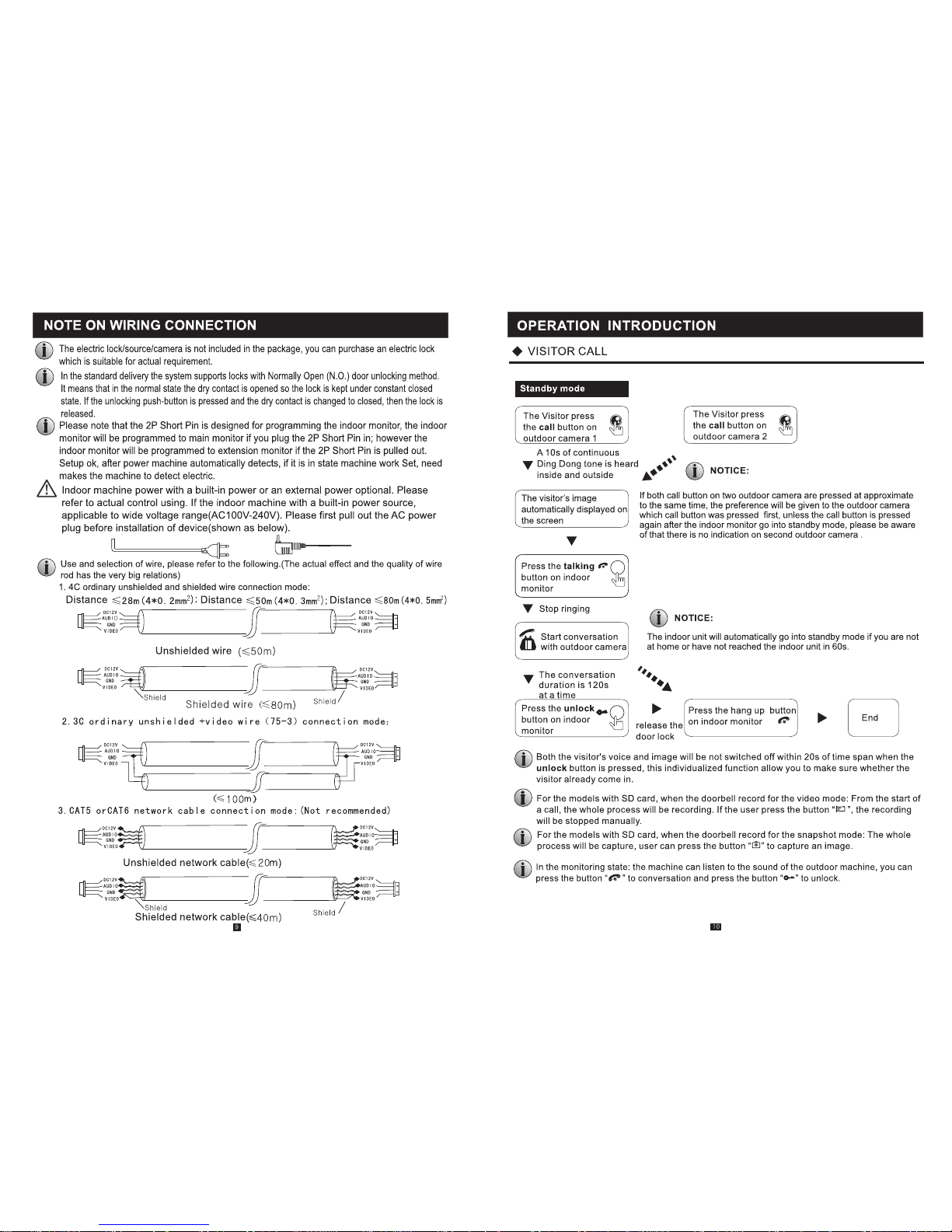
Hang up
Talk
Page 7
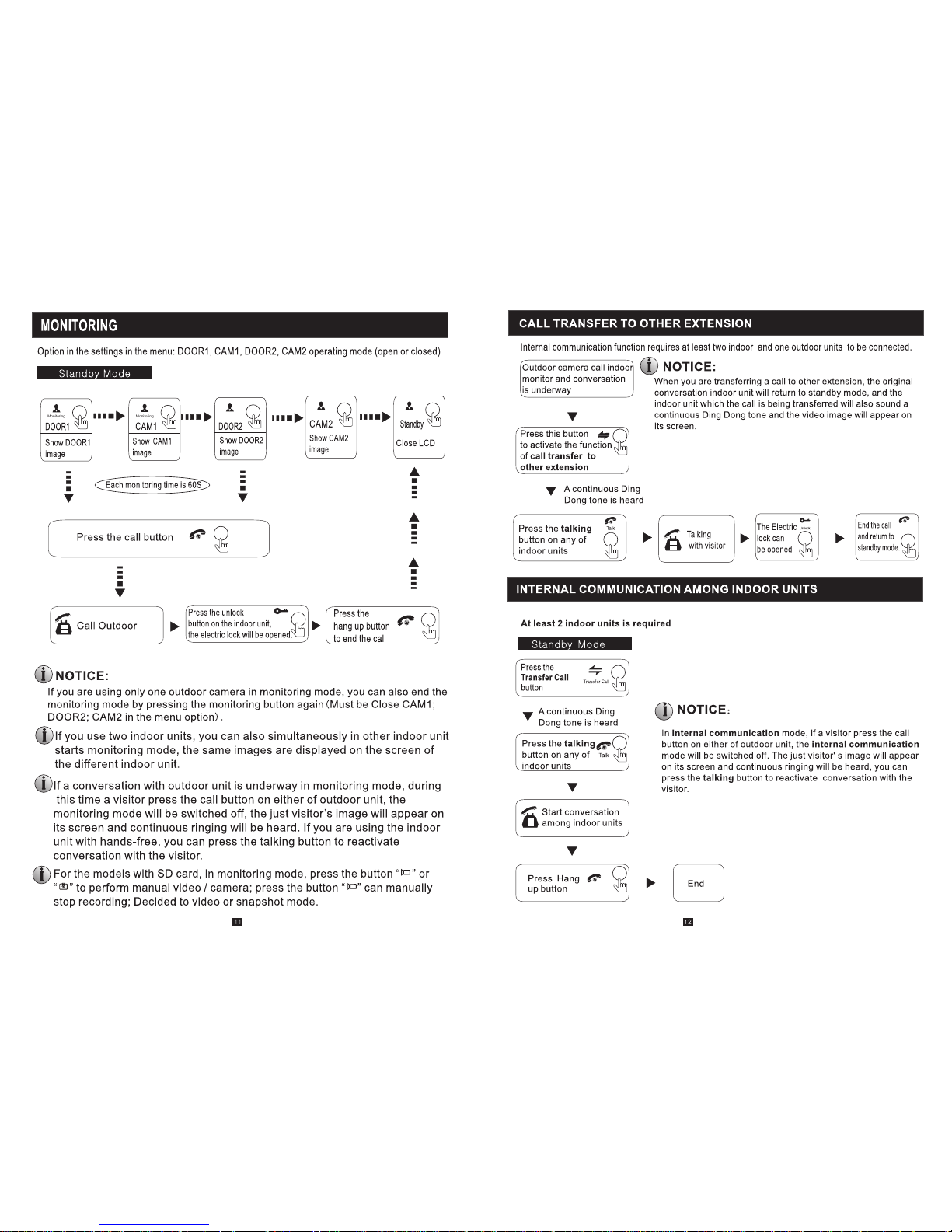
Talk
Monitoring
Monitoring
Monitoring
Monitoring Monitoring
Hang up
Hang up
Hang up
Unlock
Page 8
MENU OPERATIONS
NOTICE:
If user s don’ t do any operat e or ent er any in terf ace abo ut the i ndoor machi ne, th e indoo r devi ce
will be i nto st andby mode af ter 1 mi nute au toma tical ly.
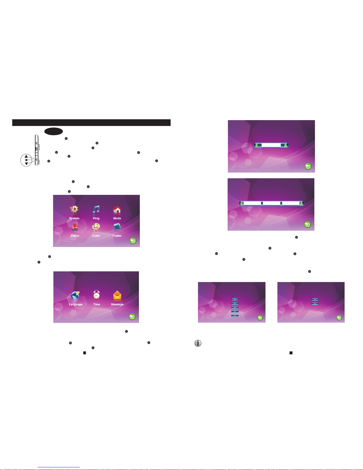
In stan dby mo de, press the b utto n “ ” to acce ss the m ain men u inte rface , show s the main
inter face a s shown below. On m enus , scrol l “ ” upwa rd or dow nwar d to move the cur sor to t he
optio n “Ret urn”, and the n pres s “ ” to exit .
The but ton “ ” is a t hree-in-o ne key, but a lso composi te key s:
In stan dby mod e, pres s the but ton “ ” onc e to enter t he main menu set tings. In main
menu se tting s, scro ll the bu tton “ ” up ward or do wnward to sele ct sub-menu, t hen
press “ ” a gain to e nter su b-men u. In sub -menu se ttings, pres s “ ” to select menu
optio ns, scr oll “ ” upw ard or do wnwar d to adjus t values of each o ption, then pr ess
“ ” to conf irm. Wh en sele ct opti on “Retu rn” on main men u, press t he button “ ” to exi t
menu in terfa ce, and t he indo or devi ce will b e into sta ndby mode.
Engli sh
YY-MM-DD 20 14-10-21 17: 05
Softwa re version: 1. 1.1.5
Releas e date: 2015-0 3-20
Format S D
Reboot
Update
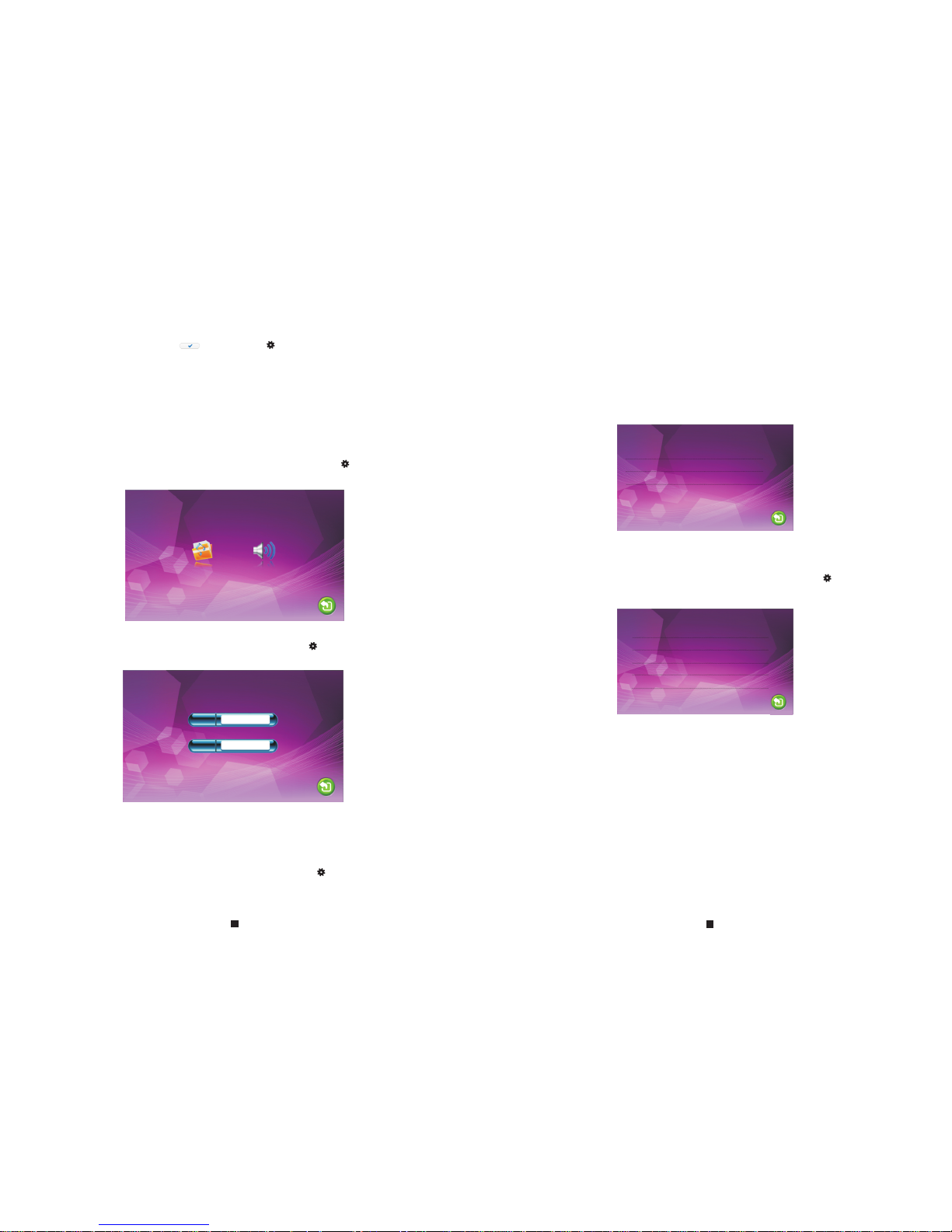
1. Set System Parameters
Scroll the button “ ” upward or do wnwa rd to mo ve the c urso r to the o ptio n “Sys tem”,
then press “ ” to enter the “System” men u. Sys tem se tup in clud es: “L angu age”,
“Time” and “Information”.
1.1 System – Language
On system menu, move the curso r to “La ngua ge” an d pres s “ ” to ent er the
“Language” menu. Use this fi eld to c hang e the la ngua ge of th e machine menu text and
the on-screen display. Press “ ” to s elec t menu options, and then scroll “ ” upward
or downward to adjust values , then p ress “ ” a gain t o conf irm.
1.2 System – Ti me
On system menu, move the curso r to “Time” and press “ ” to enter the “Time” menu.
Use this field to switch the dat e form at, in clud e “YY-MM-DD” an d “DD- MM-Y Y”, to
adjust system date and time. First
ress “ ” to select menu options, and the n scro ll “ ” upw ard or d ownw ard to
adjust values, then press “ ” ag ain to c onfi rm.
scroll “ ” upward or downward to m ove th e curs or,
and p
1.3 System – Information
On system menu, move the curso r to “In form atio n” and p ress “ ” t o ente r the
“Information” menu. The inf orma tion includes software version and release date .
optional
optional
[Format SD]:
This option is for t he models with SD card. Format SD card,
please format SD card firstly before using. – optional
Note: The product only supports those SD cards more than Class10 .
14
13
Format f lash
Back up pic tur es
Softwa re version: 1. 0.1.1
Releas e date: 2014-0 9-20
Update
Format f lash
Page 9
Ring vo l1: 06: 00~12 :00 09 30 s
Ring vo l2: 12: 00~18 :00 08 30 s
Ring vo l3: 18: 00~06 :00 07 30 s
Retur n
Mode: M aster
Door2 s tatus : On
Recor d mode: S napsh ot
Door1 u nlock t ime: 02 S econd
Door2 u nlock t ime: 02 S econd
Retur n
[Format]: This op tion i s for th e mode l without SD card. Format built-in storage of the
indoor device. – optional
[
Reboot]: Move the cursor to “ ”, and press “ ”. It will po p-up a w indo w, choos e
“Yes” to res tart t he machine, choose “NO” to cancel.
[Update]: For the models wit h SD car d, use rs can u pgra de the f irmw are of the device
via SD card. – optional
Note: During the system upgradin g, don ’t rem ove th e SD car d or tur n the in door
device disable. After completing the upgrade, the device will restart.
[Return]: Exit the current menu.
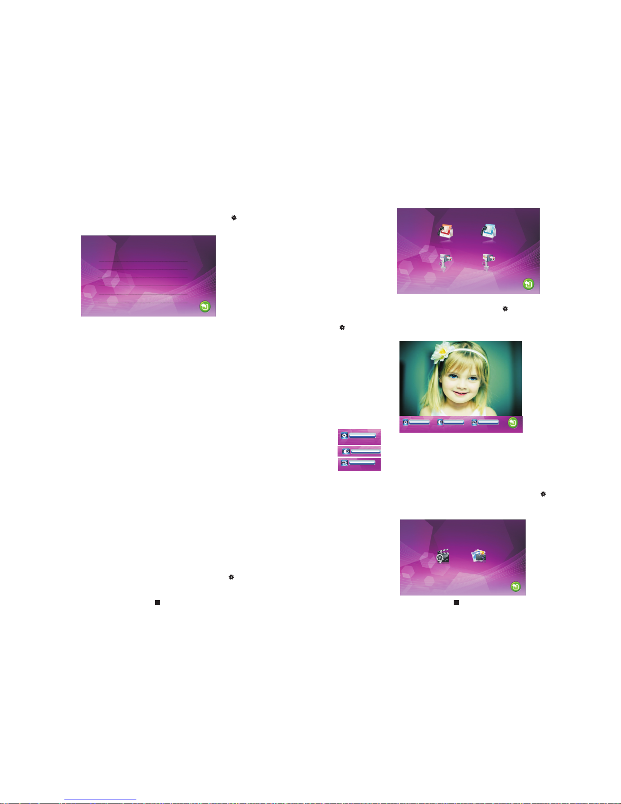
2. Set the tone parameters
On main menu, move the cursor to the opt ion “R ing” , then p ress “ ” t o ente r the
“Ring” menu. Ring setup incl udes : “Rin g sele ct” an d “Rin g volume”.
2.1 Ring – Ring select
On ring menu, move the cursor to “ Ring s elec t” and p ress “ ” t o ente r the “R ing se lect”
menu to set up the doorbell tone o f the ou tdoo r came ra.
2.2 Ring – Ring volume
On ring menu, move the cursor to “ Ring v olum e” and p ress “ ” t o ente r the “R ing
volume” menu to set up the ring vo lume . User s can se t up different ring volume during
three diffe rent t ime pe riod , the vibrate and ring time can be a djus ted fr om 10s t o 45s
when calling.
[Ring Vol1]: th e volu me lev el of Ri ng Vol1: 01-1 0.
[Ring Vol2]: th e volu me lev el of Ri ng Vol2: 01-1 0.
[Ring Vol3]: th e volu me lev el of Ri ng Vol3: 01-1 0.
Note:
The timing volume is connect ed wit h the ma nual v olum e, so pl ease s et the manual
volume to the most level, then s et the t imin g volu me. The timing volume is the volume
of internal ring chip, and the m anua l volu me is th e tota l volu me of th e power amplifier.
3. Set the mode of indoor u nit
On main menu, move the cursor to the opt ion “M ode” , then p ress “ ” t o ente r the
“Mode” menu.
[Door1]: To set up th e door bell t one of t he outdoor camera 1, a total of 12.
[Door2]: To set up th e door bell t one of t he outdoor camera 2, a total of 12.
[Return]: Exit the current men u.
[Mode]: Options include “M aste r” and “ Slav e”. “M aste r” ind icates that the indoor unit
connects the outdoors or cameras, “Sla ve” in dica tes th at the i ndoo r unit
connects the main or sub indoor unit .
[Door2 status]: Enable or di sabl e the pr evie w of Doo r2.
[Record mode]: Options include “ Reco rd” an d “Sna psho t”. “R ecord” indicates that the
device with SD card will start record automati call y when a v isit or pre ss
the call button on the outdoor camera. “Snapsh ot” in dica tes th at the
device with SD card or built-in storage will cap ture a f rame o f the
video stream as a still photo if a visitor press the c all bu tton o n the
outdoor camera.
[Door1 Unlock Tim e]: Fr om 02 se cond s to 10 seconds.
[Door2 unlock time]: From 02 secon ds to 10 s econ d.
[Return]: Exit the current menu.
15
16
Door1 0 2
Door2 0 1
Page 10
4. Set the alarm parameters
On main menu, move the cursor to t he opt ion “A larm ”, the n pres s “ ” to ent er the
“Alarm” menu.
Senso r type: N O
CAM 1 Ena ble
CAM 2 Ena ble
CAM 1 rin g time: 0 0 Secon d
CAM 2 rin g time: 0 0 Secon d
Alarm r ecord : Recor d
[Sensor type]:
CAM1]: Enable or disable the p revi ew of ca mera 1 .
[CAM2]: Enable or disable th e prev iew of c amer a 2.
[CAM 1 ring time]: Th e alar m ring t ime of c amera 1 if camera 1 has been triggered by
activity detected by the sensor, values can be set from 0~ 30
seconds.
[CAM 2 ring time]: The alarm rin g time o f came ra 2 if ca mera 2 h as bee n trig gered by
activity detected by the sensor, values can be set from 0~ 30
seconds.
[Alarm record]: Options in clud e “Rec ord” a nd “Sn apsh ot”. “ Record” indicates that
when an alarm is triggered, it will activate the c orre spon ding c hann el
to start alarm recording. “Snapshot" indic ates t hat wh en an al arm is
triggered, it will activate the correspond ing ch anne l to cap ture a
picture of the current video stream as a still pho to.
[Return]: Exit the current menu.
Each camera channel corres pond s to an I/ O stat us (se e the fo llow ing
status explanations), which means that whe n an ala rm is tr igge red, i t
will activate the corresponding chan nel to s tart a larm r ecor ding o r
capture a snapshot.
I/O status types:
NO: “Normally open”, it mean s that i n its no rmal s tate , the se nsor i s kept u nder
constant low voltage. If the outpu t volt age ch ange s from l ow to hi gh, th en the
alarm will be triggered.
NC: “Normally closed”, the n orma l stat e of the s enso r is und er con stant high voltage.
If the output voltage changes from h igh to l ow, then t he ala rm wil l be tri gger ed.
Disable: Set the I/O to “Close”, if ex tern al sen sor al arms a re not i n use.
[
5. Set the color parameters
On main menu, move the cursor to the opt ion “C olor ”, the n pres s “ ” to ent er the
“color” menu.
On the color menu the video colo r of Doo r1/D oor2 /CAM 1/CA M2 att ributes can be
adjusted for the best image qu alit y. Scroll the button “ ” upward or downward to
move the cursor to the option “D oor1 ” or “Do or2” o r “CAM 1” or “C AM2” , then press
“ ” to enter the corresponding m enu to a djus t valu es of br ight ness , contrast and
chrome depending on the actu al con diti ons.
Brightness, values can be se t up fro m 0 to 50, d efau lt as 25 .
Chrome, values can be set up fro m 0 to 50, d efau lt as 25 .
Contrast, values can be set up f rom 0 to 5 0, def ault a s 25.
[Return]: Exit the current menu.
6. Playback
On main menu, move the cursor to the opt ion “F iles ”, the n pres s “ ” to ent er the
“Files” menu. Options incl ude “R ecor d file s”(f or the m odel s with SD card) and
“Snapshot files”(for the models with SD car d or bui lt- in sto rage ).
Record f iles Snapsho t files
17
18
Page 11
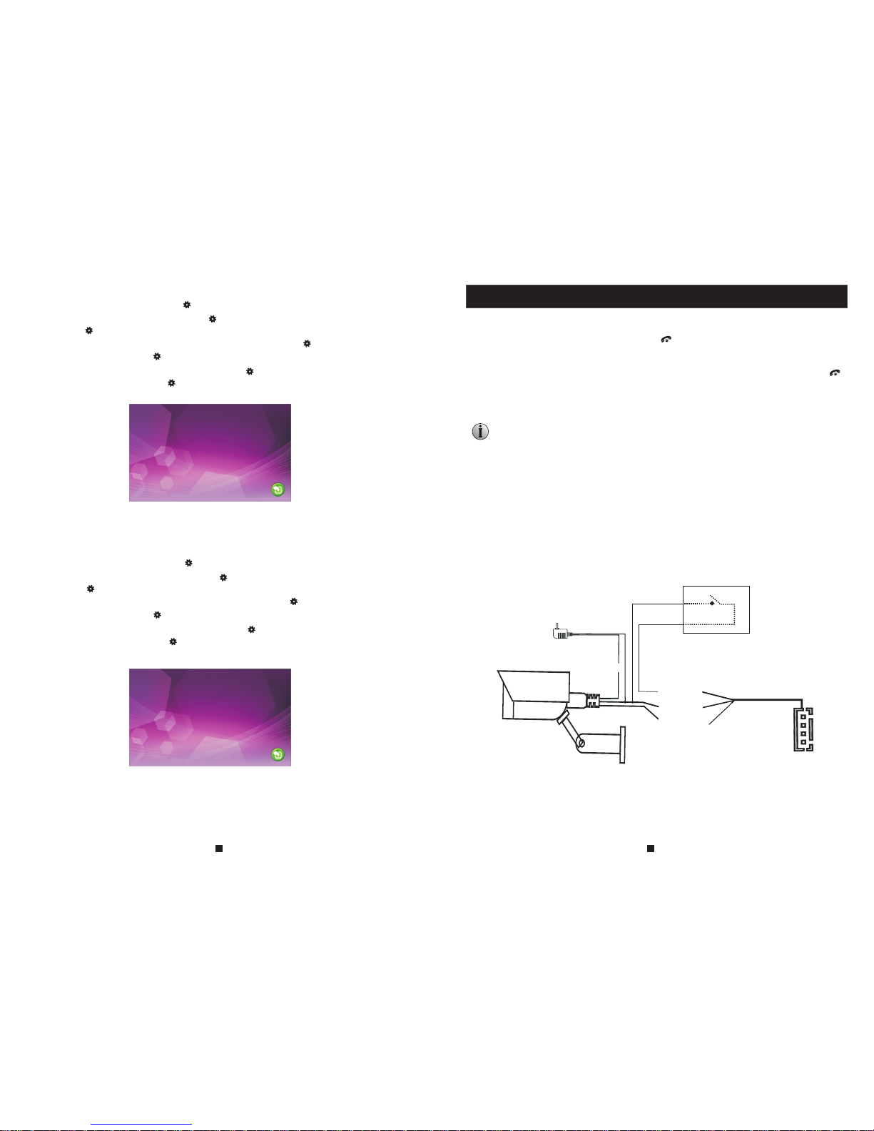
6.1 Files – Record files(optiona l, for t he mod els wi th SD ca rd)
On “Files” menu scroll the but ton “ ” up ward o r down ward t o move t he cur sor to t he
option “Record Files”, pre ss the b utto n “ ” to ent er the “ reco rd fil es lis t”. Scroll the
the button “ ” upward or downwar d to mov e the cu rsor t o sele ct fil e to pla yback, a red
list indicates that the list h as bee n sele cted , pres s the bu tton “ ” t o play back. During
playback scroll the button “ ” u pwar d or dow nwar d, it wi ll swi tch th e current video to
the last file or the next file, an d pres s the bu tton “ ” a gain t o exit . Move the cursor to
the option “Return” and pres s “ ” to exi t the cu rren t menu .
201410 21 - 152413 0005
201410 21 - 152403 0004
201410 21 - 142957 0003
201410 21 - 142911 0002
201410 21 - 142651 0001
001 / 001
6.2 Files – Snapshot files(o ptional, for the mo dels w ith SD c ard or built-in sto rage )
On “Files” menu scroll the but ton “ ” up ward o r down ward t o move t he cur sor to the
option “Snapshot Files”, p ress t he but ton “ ” to e nter t he “sn apsh ot fil es list”. Scroll the
the button “ ” upward or downwar d to mov e the cu rsor t o sele ct fil e to vie w, a red list
indicates that the list has be en sel ecte d, pre ss the b utto n “ ” to pla ybac k. During
playback scroll the button “ ” u pwar d or dow nwar d, it wi ll swi tch th e current picture to
the last file or the next file, an d pres s the bu tton “ ” a gain t o exit . Move t he cur sor to
the option “Return” and pres s “ ” to exi t the cu rren t menu .
201410 21 - 152419 0010
201410 21 - 152418 0009
201410 21 - 152402 0008
201410 21 - 152400 0007
201410 21 - 143001 0006
201410 21 - 142954 0005
201410 21 - 142925 0004
201410 21 - 142924 0003
201410 21 - 142839 0002
201410 21 - 142720 0001
001 / 002
Alarm Instructions
Hang up
Be applicabl e to c on ne ct 2 n or ma ll y cl os ed ( NC ) or n or ma ll y op en ( NO )
alarm inputs .
2 camera chann el s of a la rm i np ut w it ho ut l im it at io ns o n in pu t ty pe ( ca n ei th er
be the normall y op en t yp e or t he n or ma ll y cl os ed t yp e) .
ALM terminal o f th e al ar m de te ct or i s co nn ec te d in p ar al le l wi th t he AL M
terminal (Th e al ar m de te ct or s ha ll b e su pp li ed b y ex te rn al p ow er s up pl y) .
Ground termi na l of t he a la rm d et ec to r is c on ne ct ed i n pa ra ll el w it h th e GN D
terminal of th e ca me ra .
For NO alarm inp ut s, w he n th e GN D an d ALM a re i n th e co nn ec ti on s ta te , it
will trigger t he a la rm .
For NC alarm inp ut s, w he n th e GN D an d ALM a re i n th e di sc on ne ct s ta te , it
will trigger t he a la rm .
It applys to any ala rm s en so r.
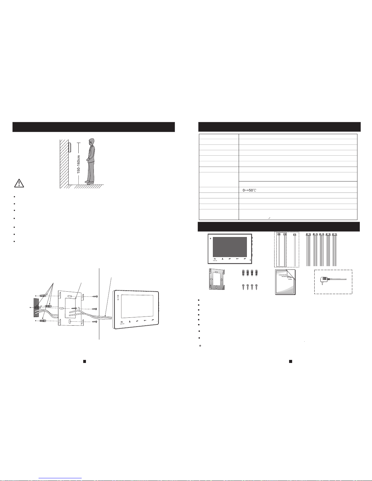
CAM1 and CAM2 of this producti on hav e each a n alar m func tion . When t he trigger
terminal and GND is shorted, t he ala rm is ac tiva te, th e spea ker of t he indoor unit rings
and continues 120s, during t his ti me, cl ick “ ” to s top al armi ng and e nter t he
standby mode.
For the models with SD card, sim ulta neou sly, triggers recording or snapshotting
(related to the system settings) . The recording time is 120s, during this time, click “ ”
to stop alarming and enter the s tand by mod e.
Connection diagram:
Hang up
19
20
G
N
D
D
C1
2V
V
i
d
eo
A
LM
CAM
G
ND
A
L
M
AC/DC p ower a dapter
for cam era( not include d)
Page 12
Specification
Accessories
Indoor unit
Indoor unit ------------ ---- ---- ---- ---- ---- ---- ---- --------------------- 1pcs
Plastic Anchors ---------- ---- ---- ---- ---- ---- ---- ---- ------------------ 4pcs
Screws ------- ---- ----------------------- ---- ----------------------- ---- -- 4pcs
Bracket ------------------ ---- ---- ---- ---- ---- ---- ------------------------ 1pcs
4 Pin line --------------- ---- ---- ---- ---- ---- ---- ---- -------------------- 5pcs
If the indoor unit includes th e inte rnal p ower s uppl y ,the re is no e xternal power
supply switch of the picture o n the ab ove.
User manual ------------ ---- ---- ---- ---- ---- ---- ---- -------------------- 1pcs
21
22
External power suppl y swit ch(O ption al) --- ---- ---- ---- ---- ---- ---- -- 1pcs
Install the indoor unit
Note:
Please be far from the intense radiation: TV, DVR , etc.devices with
Do not disassemble private ly to av oid th e elec tric s hock .
Do not drop, shake or knock the de vice , othe rwis e will d amag e the elements.
Choose the best position to in stal l, the h oriz onta l view i s 150cm.
Please power down before ins tall atio n.
Keep at a distance of more than 30 cm wit h AC pow er to av oid in terf erence.
Away fr om the w ater, ma gnet ic fie ld and chemicals.
How to install the indoor unit
plastic
stent
cables
(Optional)
Display screen
Definition
Stan dar d
Calling mode
Calling time
Standby current
Work cu rren t
Power supply
Work te mper atur e
Installation way
Built-in storage
Picture format
4 4 3 7"; 10. 1 TFT LCD screen"; . "; "
PAL/NTS C
Two-way conversation
120 s
Maximum 250M A
Maximum 600MA
Surface mounting
JPE G sta ndar d form at
SD card
(maximum 32GB)( >CIass 10)
Extension memory
(Optional)
Exter nal swi tchin g power
suppl y(DC1 2V)-- Optio nal
10.1"(1024X600 )
(Depends on goods)
Built -in pow er supp ly--O ption al
or
2 Pin line(optio nal, p lease take ac tual m odel as q uasi ) ------------ 1pcs or 2pcs
Monitoring
Unlock
Hang up
T
alk
Monitoring
Unlock
Hang up
Talk
1
2
4"(320X 240 )
4.3"(4 80X 272)
7"( )800 X4 80
Page 13

 Loading...