

Page 1
1
1080P AHD HDD MDVR
USER MANUAL
FTH-DVR-B7
Further Technology(Dongguan
)
Co., Limited
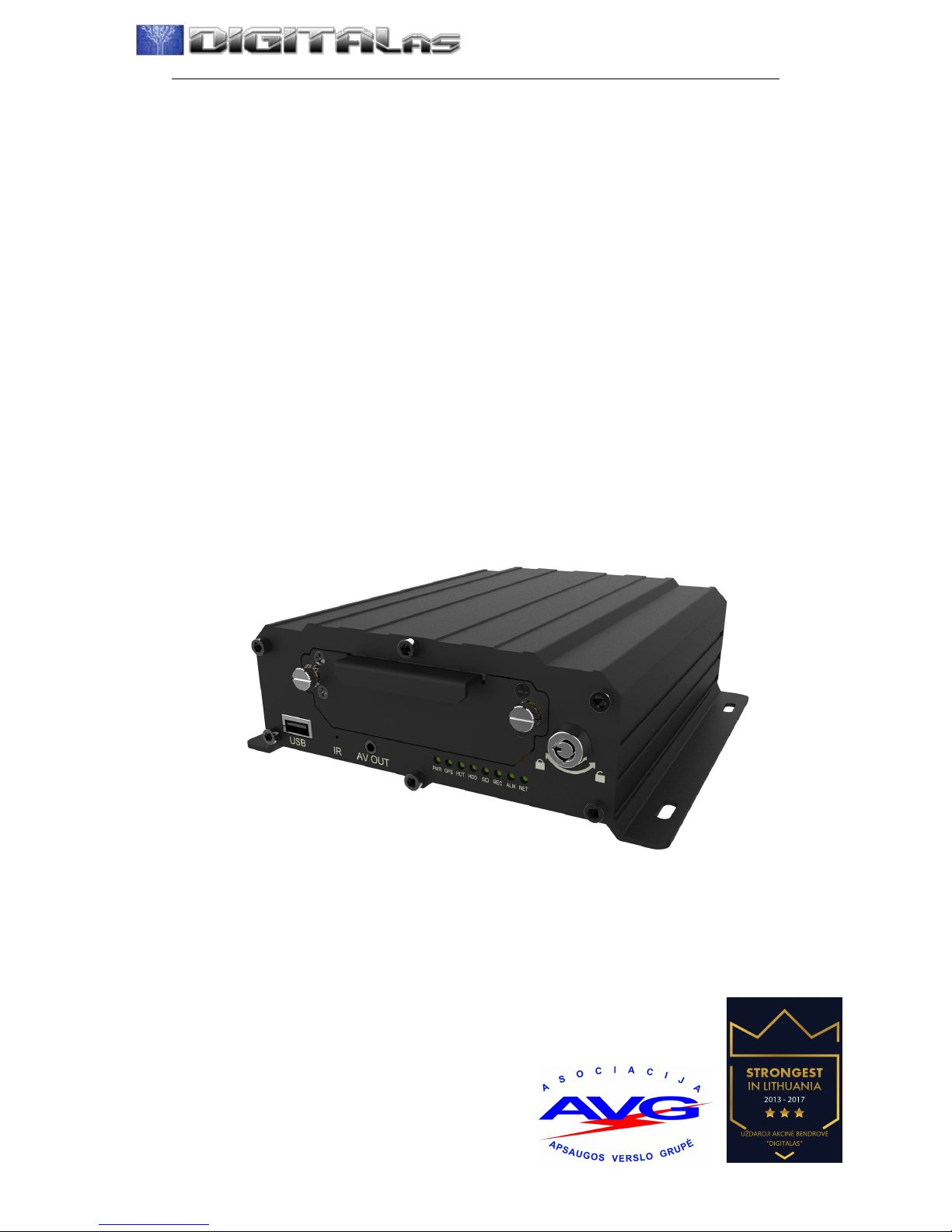
MDVR-4F1AHD professional car video recorder
Page 2

-----------------------------------------------------------------------------------------------------------------------------------
2
Contents
1. System Introduction........................................................................................................................ 3
2. Specification....................................................................................................................................4
3. Considerations.................................................................................................................................7
4. Interface Description....................................................................................................................... 9
4.1 Front Panel Description.........................................................................................................9
4.1.1 Indicator Function Description.................................................................................. 9
4.1.2 Other definitions.........................................................................................................9
4.2 Rear View............................................................................................................................ 10
4.2.1 The rear panel definition..........................................................................................10
4.2.2 Power cord special instructions............................................................................... 10
4.2.3 Audio/video input/output Description......................................................................11
4.2.4 GPS、3G/4G Antenna、Wi-Fi Antenna.................................................................13
4.3 Host installation Instruction................................................................................................13
4.3.1 Wiring diagram.........................................................................................................13
4.3.2 HDD Installation...................................................................................................... 15
4.3.3 SD card, SIM card installation.................................................................................17
5. DVR Menu Operation................................................................................................................... 17
5.1 Menu Structure....................................................................................................................17
5.2 Remote Control................................................................................................................... 19
5.2.1 System Key.............................................................................................................. 19
5.2.2 Menu-key Function Description.............................................................................. 20
5.2.3 Play Keys................................................................................................................. 20
5.3 Software operation.............................................................................................................. 20
5.3.1 Login........................................................................................................................ 20
5.3.2 Main Menu............................................................................................................... 21
6. Troubleshooting Guide..................................................................................................................39
Page 3

-----------------------------------------------------------------------------------------------------------------------------------
3
H.264 Compression Mode, Support 4CH real-time 720P AHD/1080P AHD High
Definition camera input; Exclusive pre-allocate DVR Special File System
Technology,Solving repeatedly wipe cause file fragmentation, solving SD card file
system collapse, data loss and cannot find SD card and file garbled, ensure the
integrity of the data. 8-36V Adaptive Wide Voltage input, Super Low Power
Consumption Design;HDD+SD card storage (maximum support 2TB 2.5’’ hard disk
and 128GB SD card. ) It can be completely resist car Vibration,Dust and others cause
data corruption; Support GPS/BD/G-SENSOR ; High Reliability Aviation
Connectors,High Cost Performance with reliable stability,simple and clear
operation menu .
1. System Introduction
Product features
Features Details:
HIS Solution,H.264 Compression Mode, Many stream recording, 8CH Real-time
720P and 8CH real-time 1080P High Definition mega pixels Camera input.
Real-time HD Video Recording, 1080P/720P/D1/HD1/CIF optional, Adjustable
Frame Rate Quality.
Professional Power Design for all kinds of Vehicles, 8-36V DC Wide Voltage,
Over-load, Over-voltage, Short Circuit, Reverse Protection, Suitable for all kinds
of vehicles.
Support DC12V output power for camera,mini monitor and some peripheral device.
HDD + SD card Data record storage (maximum 2TB 2.5’’ hard disk and 128GB SD
card. ),which can resist car vibration, dust and others cause data corruption;
Watchdog Abnormal will trigger Restart Protection Function. It can better protect
Device and Video.
Exclusive pre-allocate DVR Special File System Technology, Solving repeatedly
wipe cause file fragmentation, and ensure the integrity of the data.
By accidents power-off protection function. Unique UPS Technology ensures the
integrality of record when power failure occurs, even can for 10-15s.
Flame out Time-lapse Video Recording Function ( Maximum delay time 24 hours.)
Auto Recording,Time Recording,Alarming Recording Modes for Different Request.
Display vehicle traffic status, Vehicle numbers ,Route, Super-low speed vehicle
Information, Convenient management.
Page 4
-----------------------------------------------------------------------------------------------------------------------------------
4
Support GPS/BD,G-sensor Modules Extension.
3channels RS232 +1channel RS485.
Superior network function, support mobile SMS to configure parameters and obtain
device information.
Support Video&Audio monitoring,2-way Intercom, PTZ control, manually
Alarm,Over-speed,Geo Fence etc through remote control platform.
8CH alarm inputs (Doors, lights, steering, braking, reversing and all types can be
configured), Can support kinds of response linkages.
2CH alarm output, Support the linkage acousto-optic alarm, cut off fuel
oil/power,etc .
Support Local Auto-photo when alarm input,device pictures preview function;
All Aviation connectors, Super stable, High Anti-shock,Easy installation Plug in and
out.
Unique WINDOWS 8 interface, Easily Smart GUI Interface, Fluent system interface
is intuitive and perfect.
Support SD card Remote Software Upgrade/OTA remote upgrade automatically,
partition backup technology upgrade don't crash.
Support mobile phone remote monitoring, and 3G call function
Supporting the ministry of communications 808 agreement, extensible PTZ control,
POS, oil flow sensor, LED advertising screen, etc
Can be batch functional customization according to customer's requirements;
2. Specification
Item
Parameter
OS
Linux
Language
Chinese/English/Others (can be customized)
Video Compression
H.264 Compression Mode
OSD
Overlays information such as date time and vehicle ID
GUI
Graphical User
Interface
Can connect to external LED screen. Setup system parameters with the
remote control.
Video Record System
Video Input
8CH 720P AHD/8CH 1080P AHD input ,aviation connector.
Video Output
2CH CVBS+ VGA output for optional, 1.0Vp-p, 75Ω,Aviation
Preview
Support 1 channel and 4 channels preview.,Support Manual/Alarm Trigger full
screen preview
Resolution
Support 1080P/720P/D1/CIF, MAX:4 channels 1080P
Video Quality
0-7 levels, 0 is the highest level, 7 is the lowest level.
Page 5

-----------------------------------------------------------------------------------------------------------------------------------
5
Video Standard
PAL: 100f/s , CCIR625 line,50field;
NTSC: 120f/s, CCIR525 line,60field;
CIF: 256Kbps ~ 1.5Mbps, multi levels video quality optional;
HD1: 600Kbps ~ 2.5Mbps, multi levels video quality optional;
D1: 800Kbps ~ 3Mbps, multi levels video quality optional;
720P : 1Mbps~4Mbps, multi levels video quality optional;
1080P: multi levels video quality optional;
Record Mode
The default setting is auto recording after power on. Timed recording, alarm
trigger recording and manual recording are supported.
Audio
Audio Input
8CH ,Aviation Plug
Audio Output
2CH,Front port is earphone port ,rear port connects to BNC connector.
Compression
G.726 compression, 8KB/s speed
Alarm Input
8CH IO Alarm Input, 1CH AD input, pulse speed input; Support alarm linkage
function
Alarm Output
2CH Relay Alarm Output, Support the linkage acousto-optic alarm, cut off fuel
oil/power,etc
Communication Interface
3CH RS232, support extension device, such as POS machine, Oil Feul sensor,
LED advertising screen , etc.
1CH 485 interface, can connect PTZ,etc.
2CH CAN interface.
Wireless transfer
Support Built-in 3G network, WCDMA,CDMA2000,TD-SCDMA compatible with
GPRS,EDGE; Support Built-in 4G network, TTD-LTE, FDD-LTE
Position
Support Built GPS/BD Module,can make playback analysis of vehicle routing
G-Sensor
Support G-sensor
Video
Storage
Storage
2.5’’ HDD+ SD Card,each max 2TB HDD + 128GB SD Card mirror recording to
protect data from loss
Upgrade
Support USB flash disk updating,SD card upgrade , OTA remote upgrade
automatically
File Format
.ASF
File System
Special Car system File System
USB
Front panel supports USB port, support USB flash disk upgrade to backup;
hard disk box USB port, can back up video data
Video
Playback
Video Search
Search video by Record Time/Record Type etc
Playback
Max support 4CH Replay /Stop/Fast Forward/Fast Reverse at same time
Support x 2,x4,x8,x16. fast forward or fast backward play
Safety Management
User/Admin 2 Levels Different Passwords , support screen lock
Voltage &
Power
Consumpti
Power
Management
Adaptive wide power input, support Wide Voltage, Over-load、Over-voltage、
Short Circuit、Reverse Protection..Support Time Setting/Delay power off
Voltage Input
DC:+8V ~ +36V
Page 6

-----------------------------------------------------------------------------------------------------------------------------------
6
on
Voltage Output
+12V@2.5A,+5V@2.5A
Power-off
Protection
UPS Technology,All video information can be saved automatically when the
power is cut off, and make sure that all the files can not be damaged.
Power
Consumption
Normal Working <10W
Working
Environme
nt
Temperature
-20℃ to +70℃
Humidity
20% to 80%
others
Size
200 (D)* 187(W)* 65(H) mm
Net Weight
2.15kg
***** Above parameters any changes,please refer to actual product *****
Page 7

-----------------------------------------------------------------------------------------------------------------------------------
7
3. Considerations
In order to ensure the safely use of FTH-DVR-B7 Mobile DVR device, please
carefully read and observe the following precautions:
3.1 when installing and operating the equipment, comply with all the norms of
electronic products, as well as vehicles and other connected equipment.
3.2 Power and Ground:
i. The Projector range of DC input power directly 6V to 36V, often powered from
the vehicle battery (or distribution box) To take power, please be careful not to
reverse the output can not be short, please note that the power supply load line,
the positive and negative power supply line diameter must be used Φ1.5 above.
ii. even when the device is closed, also charged in the machine, to avoid short
circuits, before connecting other external devices, disconnect the device from
the power source (such as audio and video yellow and green lines in the power
supply wiring are not red phase touch and wrong).
iii. Equipment native external output voltage of 12V, only for the power supply for
the camera, do not come with any not specified on the device allows the use of
a device.
iv. correct device ground connection to the vehicle's ground wire loop composition.
v. If the machine does not use long, preferably completely disconnect the power
supply to prolong life.
3.3 Humidity::installation of equipment in a dry environment, avoid moisture, drip,
sprinkler and other places, do not install the equipment in the recess. It will place
water or liquid dripping wet places.
3.4 Installation position:
vi. To extend the life of the equipment, if possible, the equipment installed in the
vehicle vibration weaker parts.
vii. The equipment should be installed in a vehicle ventilated areas: equipment
installed on the plane should be kept 6 inches (15 centimeters) away from other
objects, in order to facilitate the flow of air and heat; can not be installed in a
closed space.External wire have enough space and outer flame tube
viii. protection devices to ensure that the wire is not bent or worn in shock and
leakage.
ix. ensure that heat away from the device on the vehicle, the device can not have
debris piled up around the forbidden place anything on the device
3.5 Device Security:
x. ensure that passengers can not interfere with the driver or damage to
equipment and parts, cameras, cables and other accessories, do not install near
Page 8

-----------------------------------------------------------------------------------------------------------------------------------
8
other vehicle components restricted areas.
xi. installation of equipment components, cameras, accessories, and when the wire,
launch vehicle may cause damage to the equipment, make sure the vehicle is
stationary during installation, to prevent the unit from dropping.
xii. screws fastening the device must be strong, can not loose, to ensure the
stability of the device.
Page 9

-----------------------------------------------------------------------------------------------------------------------------------
9
4. Interface Description
4.1
Front Panel Description
4.1.1 Indicator Function Description
[PWR] Power Status Indicator: LED lit ─ charging system
[GPS] GPS status light: LED flashes ─GPS loaded successfully
[HOT] heating status lights: Reserve
[HDD] HDD LED: LED lights ─ hard disk loading. LED flashes ─ a description of this
disc is recording or reading and writing data
[SD] SD indicator: LED lights ─SD Calgary uploaded successfully. LED flashes ─ a
description of this disc is recording or reading and writing data
[REC] Video light: LED lit indicates ─ is recording
[Alarm] machine running warning lights: When the alarm is triggered, Alarm lights lit
[NET] NET indicator: LED lights ─ network load successfully
4.1.2 Other definitions
[IR] IR receiver: for receiving remote control signals
[USB] USB interface
[LOCK] HDD Lock: no lock, the host can not start
[V-OUT] composite video signal output port
Page 10
-----------------------------------------------------------------------------------------------------------------------------------
10
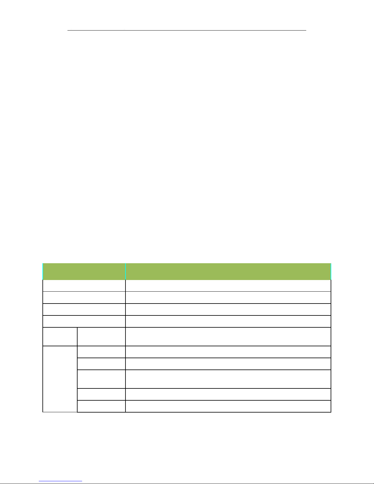
4.2 Rear View
4.2.1 The rear panel definition
● [DC8-36V] Power Interface: left upper and lower 2PIN is DC +, down the middle 2PIN
is DC-, is on the right side 1PIN ACC, under the right of 1PIN is 12V-OUT.
● [NET] network interface.
● [I/O] ALM/232/485/CAN interface。
● [PANEL] 232 / MIC / SPK expansion interface.
● [VIN1-8] audio and video input interfaces.
● [VGA] VGA video output interface.
● [3G / 4G] 3G / 4G antenna interface.
● [WIFI1-M] WIFI antenna interface.
● [GPS] GPS antenna interface.
4.2.2 Power cord special instructions
Page 11

-----------------------------------------------------------------------------------------------------------------------------------
11
4.2.2.1 Power cable pin definitions
Color Line
Name
Description
Red
DC+
Power-Positive
Black
DC-
GND
Yellow
ACC
ACC
Red
12V-OUT
12V output
4.2.2.2 Wiring: red and black wire are connected directly to the car battery. Red wire to
positive, black to negative. Yellow line contacts FireWire, ignition switch mode is set to
mode. The DVR device turns on when the vehicle power on,DVR turn off automatically the
vehicle power off. Yellow line connected to the car keys to open the position (that is,
before the automobile starter motor gear) all the dashboard lights.
Note: 1) Before connecting wires,one need to make sure the battery voltage is
between 6V ~ 36VUU, otherwise it will be burned;
2) After connecting the cable, pay attention to insulation of the line between
lines to prevent short circuit and burned out the battery;
3) yellow line must be connected to the firing line, otherwise the device will not
support the ignition switch;
4) Special Note: 12V-OUT line can not be connected to the power input by
mistake, which can not be connected to ground by mistake;
5) Note: DVR installation must be connected to battery positive and negative
directly, can not be done with ground grounding, grounding will produce negative glitch
host running. Positive and negative power supply line diameter must be Φ1.5 above.
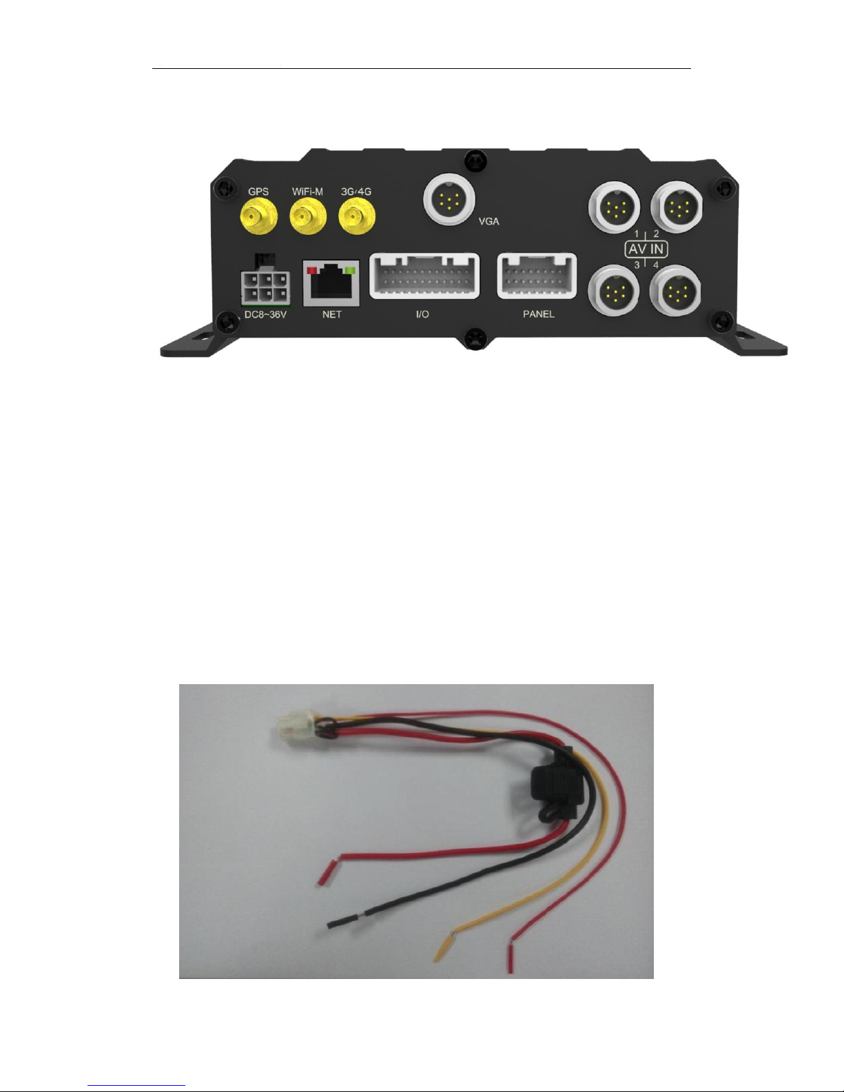
4.2.3 Audio/video input/output Description
【VIN1 -VIN4】Video output 1-4
Page 12
-----------------------------------------------------------------------------------------------------------------------------------
12
Female connector definition:
PIN123456
Function
12V output
Audio input1
GND
Video
input 1
Video
input2
Audio
input 2
Color
Red
White
Black
Blue
Yellow
Green
Male signal connector definition:
PIN1234
Function
12V output
GND
Audio input
Video input
Color
Red
Black
Green/White
Yellow/Blue
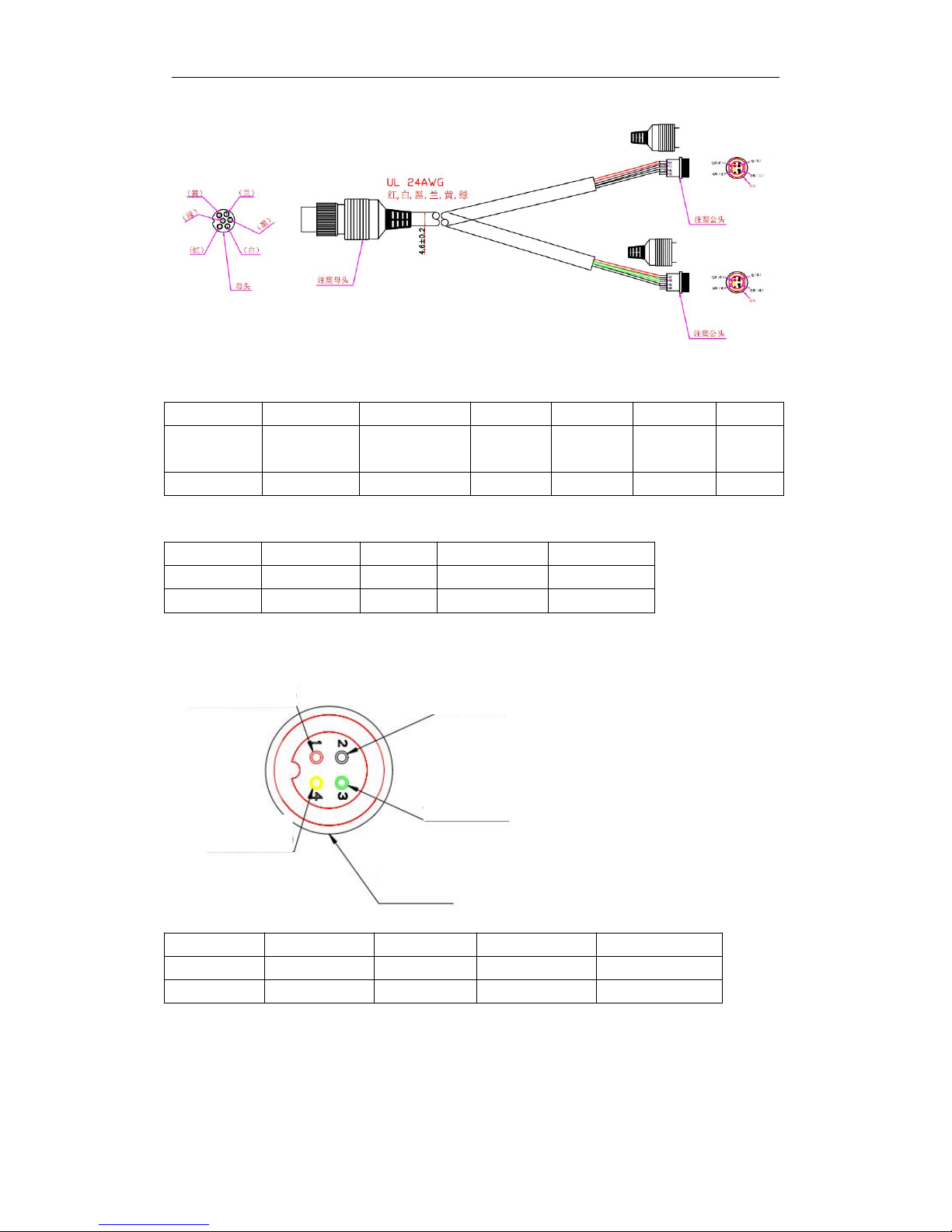
【AV-OUT】Audio/Video output
PIN1234
Function
12V output
GND
Audio output
Video output
Color
Red
Black
Green
Yellow
GND (black)
Audio (green)
+12V (red)
Video (yellow)
Female
Page 13

-----------------------------------------------------------------------------------------------------------------------------------
13
4.2.4 GPS、3G/4G Antenna、Wi-Fi Antenna
GPS Antenna 3G/4G Antenna Wi-Fi Antenna
4.3 Host installation Instruction
4.3.1 Wiring diagram
Power Line
camera4
WIFI antenna
camera3
camera2
camera1
speaker/232
Alarm lines for people counter/oil
sensor/Tyre sensor etc
3G/4G antenna
GPS Antenna
LAN/RJ45
Page 14

-----------------------------------------------------------------------------------------------------------------------------------
14
ALM/232/485/CAN connection lines
Page 15

-----------------------------------------------------------------------------------------------------------------------------------
15
ALM/232/MIC/SPK extension lines
Power Cables
Line
color
Item
Remark
Red
DC+
Power positive
Black
DC-
GND
yellow
ACC
ACC line
Red
12V-OUT
12V output
4.3.2 HDD Installation
Hard disk installation steps:
1、 Open the hard disk lock and un-screw the 2 fixing screws, pull out the hard disk
box,, as shown in FIG.
Page 16

-----------------------------------------------------------------------------------------------------------------------------------
16
2、Unscrew 4pcs screw on HDD box,as show below
3.Install shock absorption foam on both sides of the hdd, connect the HDD with
SATA lines,fix the HDD into the dedicated ditch, as shown below
HDD installation diagram
4、Closing lid, playing screws,as shown below
Lock
HDD box
Box Fixing screw1
Box Fixing screw2
HDD box screw
HDD box screw
HDD box screw
HDD box screw
ear
ear
SATA line
Page 17

-----------------------------------------------------------------------------------------------------------------------------------
17
Note: Be sure to lock the hard disk installed hard disk lock, otherwise the host may
not start.
4.3.3 SD card, SIM card installation
With a key to open the box to pull out the hard disk box, , then you can see SD card
port, as shown below. The SD card with the SD card port is pressed into place (note
positive and negative, insert the top right corner of the SD card with the notched SD
card inserted).
5. DVR Menu Operation
5.1 Menu Structure
SD slot
SIMcard slot
HDD box screw
HDD box screw
HDD box screw
HDD box screw
Page 18

-----------------------------------------------------------------------------------------------------------------------------------
18
Menu Diagram
Login
Menu
Inquiry
System Manage
Video Set
Network
Alarm Set
System Infor
Inquiry video,log,and pictures
Device infor set
User Login Set
System Parameter,Time
Video record set
Preview and OSD
Storage Parameter set
Server Parameter setting
APN Dial/WIFI set
I/O Alarm/Speed Alarm
Voltage/PTZ set
Page 19

-----------------------------------------------------------------------------------------------------------------------------------
19
5.2 Remote Control
5.2.1 System Key
【 】:
Turn on/ off key
【Info】:
Info. Key (retain)
【 】:
Lock. Press this key to lock remote input after exiting menu.
【 】:
Switch 1~4 screens. Number keys 1~4 can do this too.
Page 20

-----------------------------------------------------------------------------------------------------------------------------------
20
【Del】
:Delete key.
【
Number/Letter】Input key, you can input the number value to select a single
channel preview.
5.2.2 Menu-key Function Description
【
MENU】Start/Login/Exit menu
【
EXIT】Back to the previous menu
【 】
Last program
【 】
Next program
【 】
Modify the current item/last subproject
【 】
Modify the current item/next subproject
【OK】
Confirm
5.2.3 Play Keys
【 】:
Play/Pause
【 】: Stop
【 】:
Fast forward. 1/2/4/8/60
【 】:
Rewind. 1/2/4/8/60
【 】:
Frame forward
5.3 Software operation
5.3.1 Login
Press the remote control [MENU] key to enter the login screen:
Page 21

-----------------------------------------------------------------------------------------------------------------------------------
21
Press【OK】to enter the edit mode, input password , press【EXIT】to exit the edit,
Press【OK】to enter the Main Menu.
Original Password: 111111
5.3.2 Main Menu
【
EXIT
】
Exit Menu
Page 22

-----------------------------------------------------------------------------------------------------------------------------------
22
5.3.2.1 Inquiry
Function: Query the recording information.
Operation: In the main menu, press the remote control 【 】【 】【 】【 】 key, select
and operate.
[Image Search] Function: Search preferred video information.
Operation:In query interface, press remote control key 【 】【 】【 】【 】,select
[RECORD],press [ENTER] and go to video search Menu as below
Select the right time and search the video
Page 23

-----------------------------------------------------------------------------------------------------------------------------------
23
[Log Search]: query log information.
Operation:In query interface, press remote control key
【 】【 】【 】【 】
,select
[Log Search],press [ENTER] and go to video search Menu as below
[Image Query]: query image information.
Operation:In query interface, press remote control key
【 】【 】【 】【 】
,select
[Image Search],press [ENTER] and go to log search Menu as below
Page 24

-----------------------------------------------------------------------------------------------------------------------------------
24
5.3.2.2 System Management
Function: Set each property of the Device.
Operation:In query interface, press remote control key 【 】【 】【 】【 】,select
[System Management],press [ENTER] and go to video search Menu as below
In the System settings interface, press on the remote control 【 】【 】【 】
【 】 Keys, select the right item to set up
[Terminal Setup] Function: Change the terminal device parameters.
Operation:In query interface, press remote control key 【 】【 】【 】【 】,select
[Terminal Setup],press [ENTER] and go to the Menu as below
Page 25

-----------------------------------------------------------------------------------------------------------------------------------
25
[User Management] Function: Manage the user information.
Operation:In user manage interface, press remote control key
【 】【 】【 】
【 】
,select [User Management],press [ENTER] and go to the Menu as below
[System time] Function: set up the system time.
Operation:In system time interface, press remote control key
【 】【 】【 】
【 】
,select [system time],press [ENTER] and go to the Menu as below
Page 26

-----------------------------------------------------------------------------------------------------------------------------------
26
[Power manage] Function: set up the DVR power on/off parameters.
Operation:In power manage interface, press remote control key
【 】【 】【 】
【 】
,select [power manage],press [ENTER] and go to the Menu as below
[Parameter Set] Function: set up/Import/Export/Recover the DVR Parameters..
Operation:In system set up interface, press remote control key
【 】【 】【 】
【 】
,select [parameter manage],press [ENTER] and go to the Menu as below
Page 27

-----------------------------------------------------------------------------------------------------------------------------------
27
[Format] Function: Format DVR storage medias(USB1--HDD)..
Operation:In system set up interface, press remote control key
【 】【 】【 】
【 】
,select [format],press [ENTER] and go to the Menu as below
5.3.2.3 Record Setting
In Main Menu interface, press remote control key 【 】【 】【 】【 】,select
[video set],press [ENTER] and go to the Menu as below
Page 28

-----------------------------------------------------------------------------------------------------------------------------------
28
[Basic set] Function: Set up video record and display basic parameters
Operation:In the video set up interface, press remote control key
【 】【 】
【 】【 】
,select [Basic set],press [ENTER] and go to the Menu as below
[Main video stream] Function: Modify the main video stream parameters
Operation:In the video set up interface, press remote control key
【 】【 】
【 】【 】
,select [Main video stream],press [ENTER] and go to the Menu as below
Page 29

-----------------------------------------------------------------------------------------------------------------------------------
29
[Sub-stream] Function: Modify video sub-stream parameters
Operation:In the video set up interface, press remote control key
【 】【 】
【 】【 】
,select [Sub-stream],press [ENTER] and go to the Menu as below
[Timer recording] Function: Set up Timer recording.
Operation:In the video set up interface, press remote control key
【 】【 】
【 】【 】
,select [Timer recording],press [ENTER] and go to the Menu as below
Page 30

-----------------------------------------------------------------------------------------------------------------------------------
30
[Storage Set] Function: Set up Storage items.
Operation:In the video set up interface, press remote control key
【 】【 】
【 】【 】
,select [Storage Set],press [ENTER] and go to the Menu as below
[OSD] Function: Modify video display overlay information
Operation:In the video set up interface, press remote control key
【 】【 】
【 】【 】
,select [OSD],press [ENTER] and go to the Menu as below
Page 31

-----------------------------------------------------------------------------------------------------------------------------------
31
5.3.2.4 Network Setting
[Network] Function: Set up network parameters
Operation:In the Main Menu interface, press remote control key 【 】【 】【 】
【 】,select [Network],press [ENTER] and go to the Menu as below
[Center Set] Function: Set up network center parameters
Operation:In the Network Menu interface, press remote control key 【 】【 】
【 】【 】,select [Center set],press [ENTER] and go to the Menu as below
Page 32

-----------------------------------------------------------------------------------------------------------------------------------
32
[Local Set] Function: Set up local network parameters
Operation:In the Network Menu interface, press remote control key
【 】【 】
【 】【 】
,select [Local set],press [ENTER] and go to the Menu as below
[Dial-up settings] Function: Set up Dial-up settings parameters
Operation:In the Network Menu interface, press remote control key
【 】【 】
【 】【 】
,select [Dial-up settings], press [ENTER] and go to the Menu as below
Page 33

-----------------------------------------------------------------------------------------------------------------------------------
33
[WIFI settings] Function: Set up WIFI parameters
Operation:In the Network Menu interface, press remote control key
【 】【 】
【 】【 】
,select [WIFI settings], press [ENTER] and go to the Menu as below
5.3.2.5 Alarms and Peripherals
In the Main Menu interface, press remote control key 【 】【 】【 】【 】,select
[Alarms and Peripherals], press [ENTER] and go to the Menu as below
Page 34

-----------------------------------------------------------------------------------------------------------------------------------
34
[IO Alarm] Function: Set up IO alarm parameters
Operation:In the Alarm Menu interface, press remote control key
【 】【 】
【 】【 】
,select [IO Alarm], press [ENTER] and go to the Menu as below
[Speed Alarm] Function: Set up IO alarm parameters
Operation:In the Alarm Menu interface, press remote control key
【 】【 】
【 】【 】
,select [Speed Alarm], press [ENTER] and go to the Menu as below
Page 35

-----------------------------------------------------------------------------------------------------------------------------------
35
[Acceleration] Function: Set up Acceleration parameters, so convenient for
recording video collection
Operation:In the Alarm Menu interface, press remote control key
【 】【 】
【 】【 】
,select [Acceleration], press [ENTER] and go to the Menu as below
[Motion Detection] Function: Set up Motion Detection parameters, so convenient
for recording video collection
Operation:In the Alarm Menu interface, press remote control key
【 】【 】
【 】【 】
,select [Motion Detection], press [ENTER] and go to the Menu as below
Page 36

-----------------------------------------------------------------------------------------------------------------------------------
36
[Voltage alarm] Function: Set up voltage alarm parameters
Operation:In the Alarm Menu interface, press remote control key
【 】【 】
【 】【 】
,select [Voltage alarm], press [ENTER] and go to the Menu as below
[Serial Management] Function: Set up Serial Management parameters
Operation:In the Alarm Menu interface, press remote control key
【 】【 】
【 】【 】
,select [Serial Management], press [ENTER] and go to the Menu as below
Page 37

-----------------------------------------------------------------------------------------------------------------------------------
37
[PTZ control] Function: Set up PTZ control parameters
Operation:In the Alarm Menu interface, press remote control key
【 】【 】
【 】【 】
,select [PTZ control], press [ENTER] and go to the Menu as below
5.3.2.4 System information
[System Information] Function: Check syetem key parameters
In the Main Menu interface, press remote control key 【 】【 】【 】【 】,select
[System Information], press [ENTER] and go to the Menu as below
Page 38

-----------------------------------------------------------------------------------------------------------------------------------
38
Click【ENTER】,go to next page:
Page 39

-----------------------------------------------------------------------------------------------------------------------------------
39
6. Troubleshooting Guide
Question
Possible reasons
Solutions
Device does not work
and
there is no indicator light
working.
a. Wrong wiring connection
b. Not install power input
fuse
c. Input fuse is burned off
a. Right wiring connection
b. Install fuse
c. Replace fuse
There is no video output,
but power indicator is
light.
a. Wrong wiring connection
b. Monitor is off.
c. DVR lock is Off
d. ACC is not connected with
ignition wire.
e. Device is set as timer
recording
a. Right wiring connection
b. Start monitor
c. DVR lock is On
d. ACC is connected with
ignition wire.
e. Turn on device with
remote control.
There is video output,
but
cannot be query video
file.
a. SD Card is damaged.
b. No SD card in device
c. SD Card not format
d. Device does not record
a. Replace SD card
b. Insert SD card
c. Format SD card and
restart device
d. Check whether the video
mode of the device is on
the boot recording
Device is Off after
working 30 minutes.
a.ACC is not connected with
ignition wire
a.ACC is connected with
ignition wire
Some channels images
are black screen.
a. This channel is not connected to
the video
b. Camera damage or work
exception to this channel
c. Connection to this channel cable is
not good or damage
a. Connection video
b. Check the camera is normal or
not.
c. Check channel cable
3G is not on line (limited to
3G network)
a. 3G card is not inserted
b. 3G card is not open or no money
c. 3G network setup error
d. Server IP, port, device number
setting error
a. Check whether the 3G card is
inserted.
b. Check whether the 3G card is
open and whether there is a
fee
c. Check whether 3G network
settings are correct
d. Check whether Server IP, port,
equipment number is correct
 Loading...