

Page 1
Monitor DMV-M01
User Manual
Page 2
Description
Monitor DMV-M01 is a device designed for resident video conversation with guest. DMV-M01
should be installed indoors. It is possible to connect to monitor both addressable system (such as DD5000, DD-5100) and individual intercom module (SAC5C-CK). Monitor has hands free function.
4
5
6
10
1 2 3
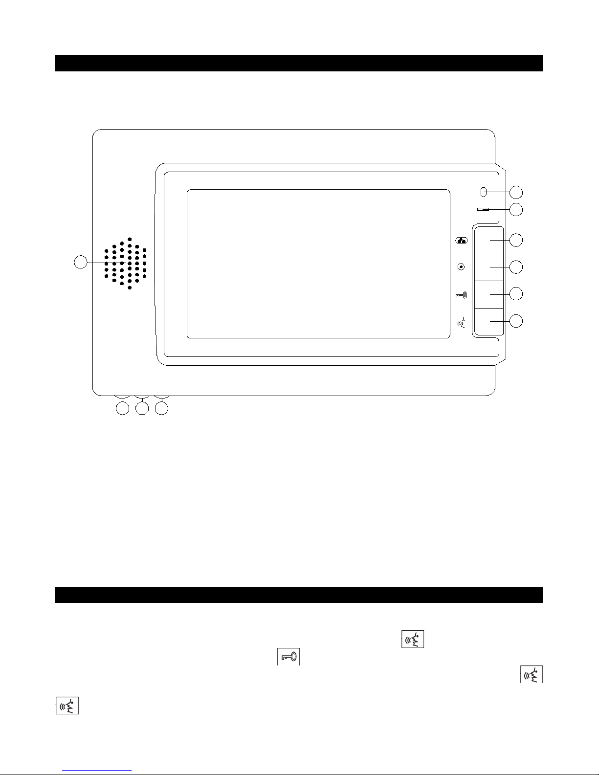
fig. 1. Structure of DMV-M01 Monitor
1: conversation sound level adjustment,
2: video image brightness adjustment,
3: video image saturation adjustment,
4: microphone,
5: LED indicator,
6: video surveillance button,
7: address programming button,
8: door opening button,
9: conversation start/end button,
10: speaker.
7
8
9
How to use monitor
Monitor starts ringing and video appears on screen when guest initiates conversation either from
addressable system or from individual intercom module. Resident sees guest on the screen and decides
whether to answer the call. Conversation with guest starts when button is pressed. Resident can
open doors after he answered call, by pressing button. If guest is calling from addressable system,
guest can end conversation by pressing cancel in doorphone keyboard, or resident by pressing
button. If guest is calling from individual intercom module, resident can end conversation by pressing
button. In stand-by mode, resident can watch surroundings by using individual intercom's camera,
Page 3

by pressing button. By pressing once again, monitor goes back to stand-by.
Specifications
Power supply voltage: 12-13,5V DC
Current consumption (stand-by/conversation): 0,1A/2A
Screen diagonal: 7 inch
Height: 160 mm
Width: 245 mm
Thickness: 17,5 mm
Wiring diagram
Wiring diagram of DMV-M01 monitor is shown in fig. 2.
LINE
violet
VIDEO
white
V+GNDAUDIO
black
red
LINE
VIDEO-VIDEO
+
-
LINELGND
+
POWER
POWER
-
- +
12-13,5V DC
Power Supply
+
white
yellow
blue
red
Power
supply
VIDEOV+GNDAUDIO
EL.
EL.
LOCK
LOCK
black
+
-
black
ELECTRIC
LOCK
fig. 2. Wiring diagram of DMV-M01 monitor
Power supply:
Positive power supply contact should be connected to (+) contact of monitor (red wire).
Common wire (ground) should be connected to (-) contact of monitor (black wire).
Video signal from doorphone:
Video signal can be fed to monitor DMV-M01 over coaxial cable or twisted pair. If coaxial
cable is used, shield of the cable should be connected to (-) contact of monitor in VIDEO segment, and
center wire connected to (+) contact of monitor in VIDEO segment. Jumpers coax1, coax2 and coax3
Page 4

should be according to which connection type (coaxial cable/twisted pair) is used. If coaxial cable is
used jumpers coax1, coax2 and coax3 should be placed. If differential video signal is fed over twisted
pair, non inverted signal caring wire should be connected to (+) contact of monitor in VIDEO section,
and inverted to (-) contact. In this case jumpers coax1, coax2 and coax3 should be taken off.
Differential signal from common mode (signal from camera) is obtained by using converter (BALUN).
Common mode signal from camera is fed to converter, at converter output differential signal is
obtained, which can be fed directly to monitor or through differential splitter to several monitors.
Sound signal from doorphone:
Positive (LINE) signal of the doorphone should be connected to (+) contact of monitor in LINE
section. LGND signal of the doorphone should be connected to (-) contact of monitor in LINE section.
Individual intercom module:
Individual intercom module is connected to monitor with four wires (from monitor side):
VIDEO (violet wire), V+ (power supply for individual intercom module – white wire), GND (ground –
black wire), AUDIO (red wire).
Address programming of the monitor
Address of monitor is programmed by placing PROG jumper. Address can be entered in two
ways:
a) by calling to desired address from doorphone (audio wires should be connected to doorphone),
b) by entering desired address using buttons. Right after PROG jumper is placed address = 0. By
pressing button, address is incremented by one(button press is indicated by blue LED flash), by
pressing button, address is incremented by ten (button press is indicated by green LED flash), by
pressing button, address is incremented by hundred (button press is indicated by red LED flash).
Address programming process should start with hundreds, followed by tens and ones. When jumper is
removed, monitor shows programmed address by flashing LED's (count of red LED flashes indicates
hundreds of address, count of green LED flashes – tens and count of blue LED flashes – ones), then
address is stored in memory. Possible addresses should fall in to range [1, 255]. If mistake was made,
simply repeat operation (place PROG jumper, enter address and remove PROG jumper).
If programmed address needs to be known, just place PROG jumper and remove without entering any
address by any way.
Address entering method a) has priority over method b). Once address entered by method a), address
won't by programmed by b) method at this session. If address was entered using method b), address can
be entered by method a).
 Loading...