

Page 1

DIGITALas, JSC
Ukmergės 234A, Vilnius, LT-07160
Tel :+370 5 2336619
info@digitalas.lt www.digitalas.eu
Page 2
Digital Door phone
DD-5100
Page 3

Table of Contents
Chapter 1. About DD-5100 door phone.........................................................................................................3
1.1. General features of the DD5100 Digital Door phone........................................................................3
1.2. Dimensions.........................................................................................................................................4
Chapter 2. Components of the System...........................................................................................................6
Chapter 3. Connection of DD-5100 door phone............................................................................................7
3.1. A standard wiring diagram.................................................................................................................7
3.2. Video camera wiring diagram............................................................................................................8
3.3. Door phone connection to the network..............................................................................................8
Chapter 4. Programming menu description.................................................................................................15
4.1. Activation of programming mode:...................................................................................................15
Leaving programming mode:.........................................................................................................15
4.2. Programming menu overview..........................................................................................................15
4.3. DD-5100 programming manual.......................................................................................................21
4.3.1. Actions with identificators........................................................................................................21
Add a new identificators................................................................................................................21
Add Service identificators.............................................................................................................21
Auto Add function.........................................................................................................................22
Delete identificator........................................................................................................................22
Delete identificator, related to sequence number......................................................................22
Delete identificator, related to user ID......................................................................................22
Delete all identificators from the memory................................................................................22
Delete system identificator, related to sequence number..........................................................22
4.3.2. Actions with codes....................................................................................................................22
Set/change users door unlock code................................................................................................23
Change Service PIN (SPIN) code..................................................................................................23
4.3.3. System settings.........................................................................................................................23
Setting of unlock delay time..........................................................................................................23
Selection of a lock type..................................................................................................................23
Access control settings...................................................................................................................24
Door unlock timer in error case.....................................................................................................24
4.3.4. Volume control..........................................................................................................................24
Indoor volume control...................................................................................................................25
Outdoor volume control.................................................................................................................25
System signals sound control.........................................................................................................25
4.3.5. User (subscriber) administrating..............................................................................................25
Disable...........................................................................................................................................25
Disable a user according to ID..................................................................................................25
Disable a group of users ID.......................................................................................................26
Enable............................................................................................................................................26
Enable a user according to ID...................................................................................................26
Enable a group of users ID........................................................................................................26
4.3.6. Setting of addressing................................................................................................................26
Regular addressing.........................................................................................................................26
Shifted addressing..........................................................................................................................26
Hotel addressing............................................................................................................................27
4.3.7. Network settings.......................................................................................................................27
a) main menu (default configuration – network disabled). ...........................................................28
b) network settings menu for L type configured doorphone. ........................................................28
c) network settings menu for H type configured doorphone.........................................................28
4.3.8. Reset to factory settings............................................................................................................29
Chapter 5. Doorphone net types and configuration.....................................................................................30
1
Page 4

DD-5100
5.1. Introduction to Net configurations...................................................................................................30
5.2. Ways to connect DD5100 to Network (Net types)...........................................................................30
5.2.1. NET1........................................................................................................................................30
5.2.2. NET2 .......................................................................................................................................30
5.2.3. NET3........................................................................................................................................31
5.3. Network configuration.....................................................................................................................31
5.3.1. Net configuration examples......................................................................................................31
5.4. Error codes.......................................................................................................................................31
Chapter 6. Error, its identification and troubleshooting...............................................................................32
User Manual.................................................................................................................................................33
1. How to use a door phone:....................................................................................................................33
2. Entering from outside..........................................................................................................................33
3. Internal door unlock............................................................................................................................33
4. Changing of user’s PIN code:.............................................................................................................33
5. Programming of new identificators.....................................................................................................34
2
Page 5

Chapter 1. About DD-5100 door phone
DD-5100 is a cutting edge nowadays door phone of a high protection level and a modern design, intended
for blocks of flats and could be used in an unfriendly environmental conditions.
Door phone is created, considering the cutting edge technical solutions. Outdoor station panel, system
controller, commutator and other parts are integrated in one unit of a door phone, so less material is used for
mounting the system and more time is saved.
2 mm stainless steel outdoor station panel of a new design contains a bright and resistant to external
influence and kicks of vandals, LED display. A outdoor station panel of small dimensions (width – 120 mm, height –
206 mm) could be easy mounted even in narrow areas (options: inserted panel or mounted above the plaster).
Keyboard light switches on automatically only in dark period, so more electricity is saved. A new generation
keyboard of a door phone is resistant to kicking. Similar keyboards are used in cash points with buttons, able to
withstand more than a million pressings.
There is a possibility to reduce system sound signals to the minimum (a high level of sound usually annoys
residents of the first floor), when keeping the same conversation sound.
Comfortable handsets suit for a modern interior. Due to mounted plug-switch a call sound could be switched
off at nights. Entrance doors could be opened using an individual 4-digits door unlock code, presented to each flat.
Residents could independently program or change door unlock codes and extra Tags; an operation lasts only 2-3
minutes.
1.1. General features of the DD5100 Digital Door phone
• Possibility to connect up to 255 users
• Duplex audio connection
• Two-Wire connection line
• TM Tags reader *
• RFID Tags reader *
• Internal memory of 1376 Tags
• Individual door unlock code
• Possibility to turn-off door unlock codes
• Possibility to add six Service Tags **
• The doors could be opened: by entering the door unlock code, using TM or RFID Tags, by pressing door
unlock button, or during conversation with a guest by pressing unlock button on the handset
• Operating temperature -40 C
o
to +85 C
o
• Small dimensions – 120x260x30 mm
• All system is supplied by a sole power supply 12V
• Low energy consumption. Duty mode with keyboard light – 12VDC, 85 mA + electric flow of electric lock
• Error indication
• Digital volume control of loudspeaker, microphone and the system sound separately
• Possibility to disable separate users or disable door unlock function
• Three types of addressing: regular, shifted and hotel
• A bright 4-digits LED display
• Keyboard with buttons, able to withstand more than a million pressings
• Possibility to install a video camera
• Options: inserted panel or mounted above the plaster
• Audible and visual indication
• Automatic lightening of a keyboard during a dark period
• Possibility to connect several systems to a network
• Protection of Service PIN (SPIN) code
• Protection from an electroshock
• Unlimited amount of Tags, related to one User's ID
• Comfortable and easy system programming
• Possibility to program/change door lock codes by the User interface
• Possibility to program TM/RFID Tags by the User interface
* DD-5100T – door phone with TM Tag reader, DD-5100R – door phone with TM and RFID Tag readers
** Service Tags are used in order to simplify system servicing (Page 15. Activation of Programming mode)o
3
Page 6
DD-5100
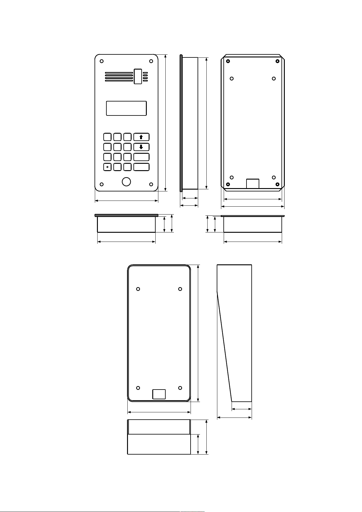
1.2. Dimensions
4
1 2 3
4 5 6
7 8 9
ENTER
0
#
CANCEL
120
110
110
30
33
30
31
30
33
261
120
251
110
263
122
30
33
30
33
Fig. 1: Dimensions of DD-5100 door phone
Fig. 2: Dimensions of door phone rain shield DR-1
Page 7
5
120
110
110
30
32
30
31
30
32
261
120
251
110
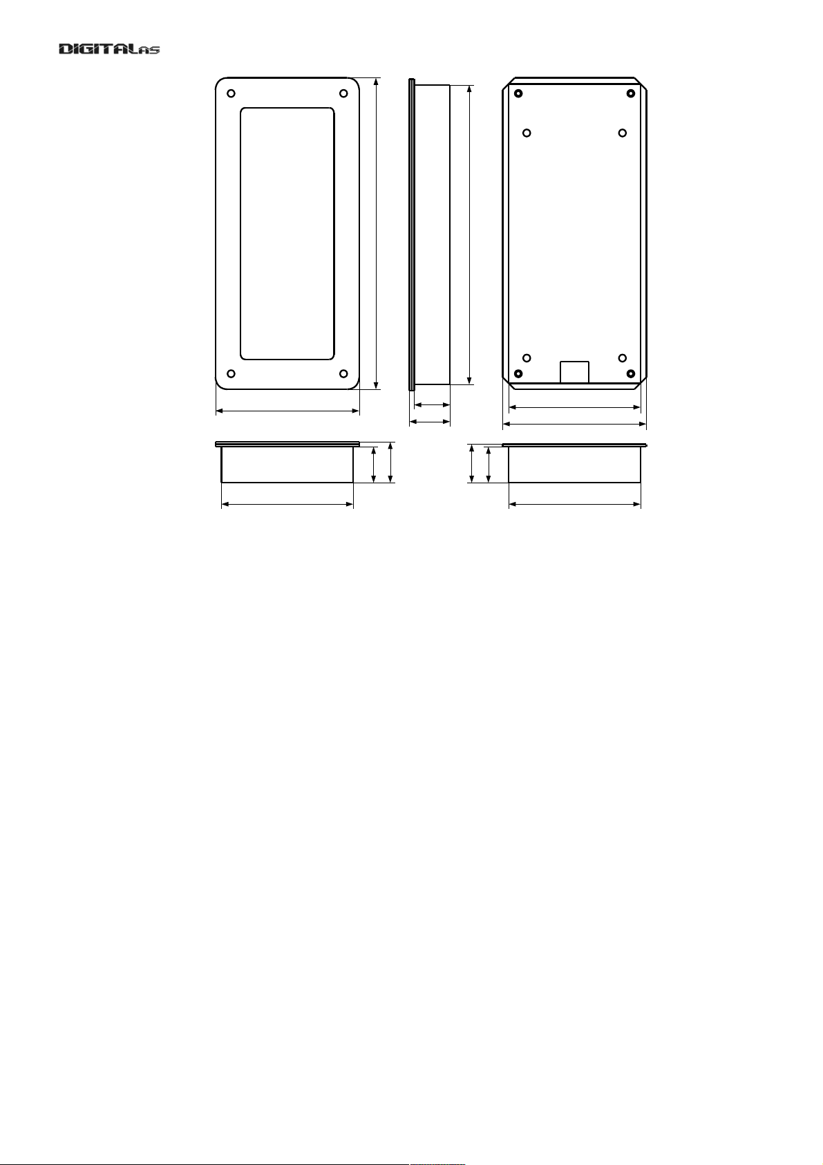
Fig. 3: Dimensions of Name frame NF-1
Page 8

DD-5100
Chapter 2. Components of the System
Call module of a door phone DD-5100
Call module is the main unit of a door phone system with a loudspeaker, microphone and a 4-digits LED
display, also anti vandalism keyboard, and electronic Tag readers. Possibility to install a video camera.
DD-5100T – call module with TM Tag reader
DD-5100R – call module with TM and distant RFID Tags reader
Door phone rain shield DR-1
Door phone rain shield is needed in order to arrange a door phone DD-5100 in the easiest way, avoiding
insert into a plaster. Rain shield protects an appliance of direct rain and other environmental factors.
Name frame NF-1
Name frame NF-1 allows to write surnames of residents, titles of companies, to introduce advertisement
texts etc. NF-1 is made of stainless steel panel, double organic glass mount with lightening and paper for printing
your information. Surname frame matches design and dimensions of DD-5100, so could be mounted together.
Power supply
12 VDC 1.5 a stabilized power supply for the whole door phone system
Electronic lock
DD-5100 call module could manage two types of electric locks (electric opener and electromagnetic lock),
managed by a permanent 12V flow. A nominal flow for electric lock must not exceed 0.8A. Lock type and locking
delay time are set by the program.
Door unlock button
Door unlock button used for unlocking the door, when leaving the object. In this case any standard button
with normally opened contacts is used.
Audio handsets
DD-5100 door phone could be connected with DG-H1 and DG-H2 type receivers, installed to all subscribers
in order to talk to a guest, calling from the outside call module. After the conversation one has a possibility to unlock
the door, pressing a button on a conversation appliance. DG-H1 contains another extra button, used for unlocking
of the second entrance door or corridor door. Sound of receiver’s signal could be switched off by the switch,
mounted on a conversation appliance.
Video/audio adaptor ADV 100
ADV 100 allows to connect analogous video/audio devices.
Network connection adaptor DD-S2.1
In order to connect two or more call modules to a network, DD-S2.1 adaptor could be used. Three call
modules could be connected using one adaptor. In order to connect more modules with one adaptor, cascade DDS2.1
6
Page 9
Chapter 3. Connection of DD-5100 door phone
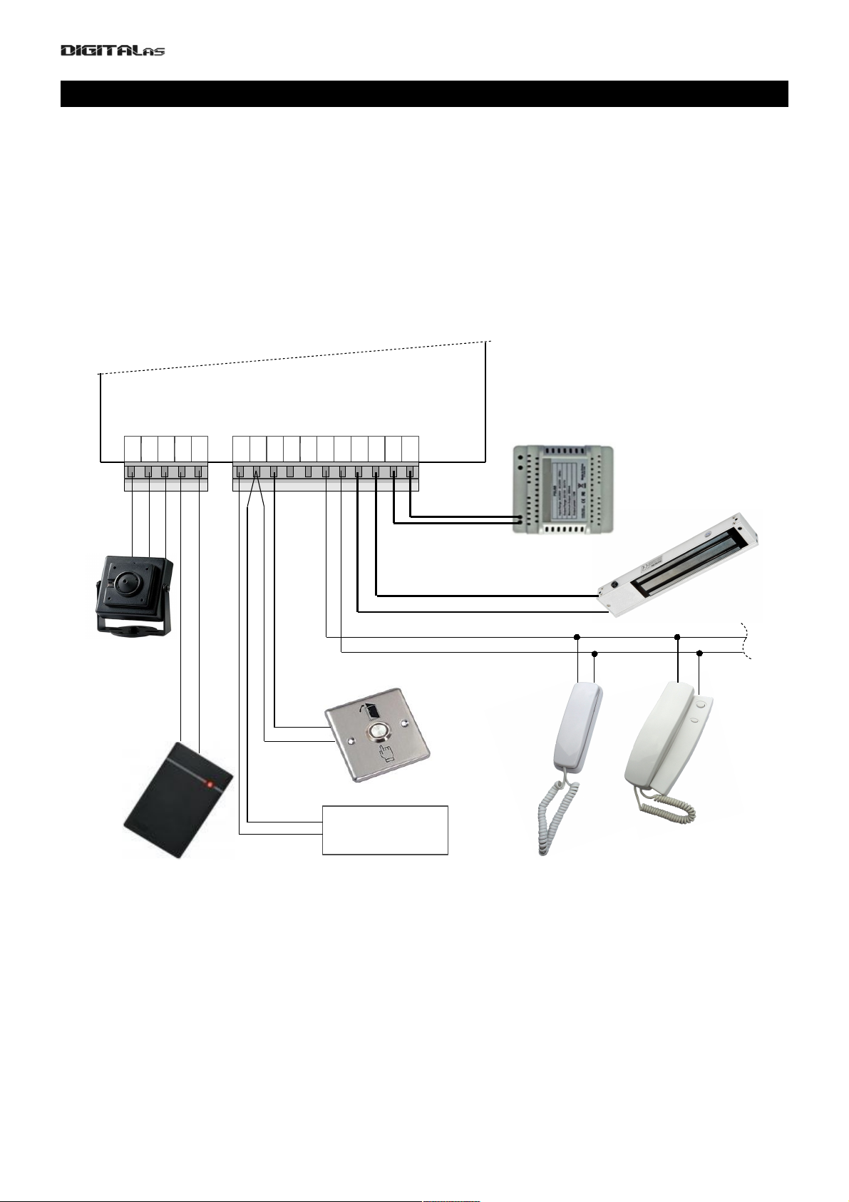
3.1. A standard wiring diagram
For basic usage of DD5100 doorphone, only connections made to right connector (see Fig. 4) are
mandatory. A minimal standard DD-5100 door phone completion involves:
• Door phone module DD-5100
• Stabilized power supply (12V, 1.5 A)
• Electronic lock
• Door unlock button
• Door phone handsets.
Left connector is dedicated for camera or external RFID reader.
Requirements for wire diameters are given in table 1.
Main contacts (mandatory connections, needed for basic doorphone operation):
GND, LGND – ground contact.
P12V – power supply positive contact,
UNL – contact of inner door opening switch,
LINE – positive line contact (line connects all handsets to doorphone),
LC- – negative contact of electric lock or electromagnet,
LC+ – positive contact of electric lock or electromagnet. By default doorphone drives electromagnet. To
drive electric lock, appropriate settings should be done in doorphone settings menu, please refer to menu section
3.2 on page 18.
Additional contacts (used to implement specific features):
D0, D1 – contacts for „Wiegand“ protocol based RFID reader data lines. RFID reader works only with
special software equipped DD5100 (if during boot R0T0, R1T1 or R1T2 appears on screen, Your DD5100
7
L-IN
LINE
LGND
LC-
LC+
GND
P12V
Regulated DC
Power Supply
(12VDC, 1.5A)
Door unlock
switch
Communication line
Handsets
Name list frame
lighting (12V, 300mA)
UNL
GND
ILMN
BUS
D1
D0
CPW
GND
CAM
Fig. 4: DD5100 digital doorphone wiring diagram
Page 10
DD-5100
supports RFID reader),
GND – ground contact for camera,
CAM – contact to connect video signal cable (wire of camera's video signal needs to be soldered to
soldering area near CAM contact),
CPW – positive power supply contact for camera module – during conversation through this contact
doorphone supplies power to camera.
Table 1: Electric installation wire upon the length
Wire*/length Up to 20 meters Up to 100 meters Up to 200 meters
Handset connection line wire
D=0,5mm / S=0,2mm
2
2 x D=0,5mm / S=0,4mm
2
System power supply wire
S=1mm
2
– –
Electric lock wire
S=0,5mm
2
– –
Door unlock button wire
S=0,5mm
2
– –
*Use a copper wire for installation
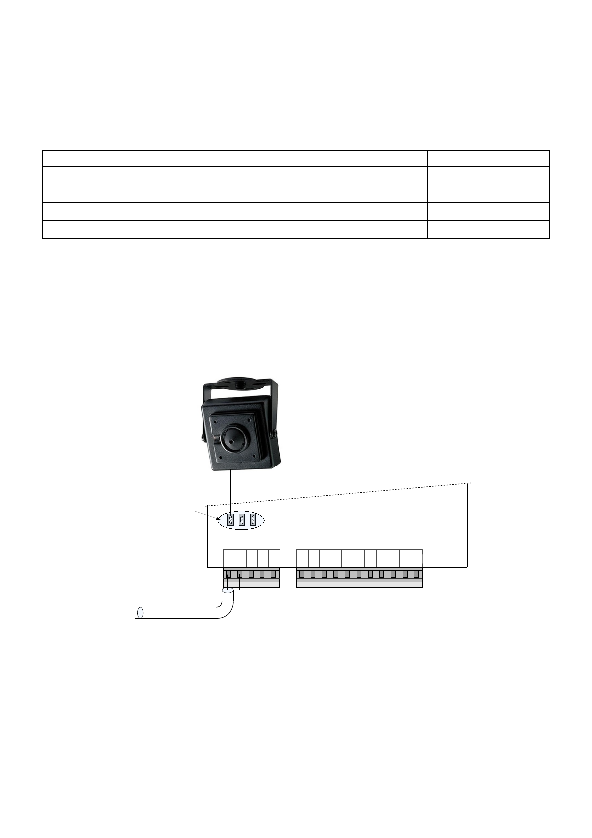
3.2. Video camera wiring diagram
There is a possibility to mount a video camera to a door phone module. See fig. 5 for video camera wiring
diagram. Pay attention, a contact “CAM” is not connected to a door phone circuit, as it is intended for commutation.
GND – ground contact, CPW – video camera power supply contact, 12 V voltage appears when calling and during
conversation session.
In order to ensure quality of image, use a coaxial wire for transfer of video signal.
3.3. Door phone connection to the network
A network connection is needed in case a room (residential house or office) has several entrances. In this
case a door phone module DD-5100 is mounted for each entrance. Several configurations are possible.
If only two doorphones in a network are needed, simplest solution is connect two DD-5100 as shown in fig. 8.
In this configuration one DD-5100 doorphone needs to be configured as L type, and NET1 configuration selected,
other DD-5100 should be configured as H type with NET1 configuration selected. Please refer to Chapter 5
“Doorphone net types and configuration“ for more info.
8
L-IN
LINE
LGND
LC-
LC+
GND
P12V
UNL
GND
ILMN
BUS
D1
D0
CPW
GND
CAM
Wires soldered to
soldering areas
Video signal
Coaxial cable
Fig. 5: Video camera wiring diagram
Page 11
L-IN
LINE
LGND
LC-
LC+
GND
P12V
UNL
GND
ILMN
BUS
D1
D0
CPW
GND
CAM
L-IN
LINE
LGND
LC-
LC+
GND
P12V
UNL
GND
ILMN
BUS
D1
D0
CPW
GND
CAM
DD-5100 configured as H type DD-5100 configured
as L type
Electric lock/electromagnet
Regulated power
supply (12VDC 1,5A)
Door unlock
switch
GND
+12V
Door unlock switch
Regulated power
supply (12VDC 1,5A)
GND
+12V
Electric lock/electromagnet
C
o
m
m
u
n
i
c
a
t
i
o
n
l
i
n
e
Handsets / Monitors
Video splitter
VD-1x5
VIN
VO5VO1 VO2 VO3 VO4
12V
GND
Power supply
(12VDC 0,3A)
Monitor
power supply
LG
CLCG
V+
GND
Wires soldered to
soldering areas
Fig. 6: Wiring diagram for two DD-5100 call modules, NET1 configuration
Page 12

DD-5100
In this configuration user sees video only from that doorphone, which is connected with his/her monitor. For
example first DD-5100, configured as H type and NET1 configuration selected, is mounted at the gates of closed
yard, second DD-5100, configured as L type and NET1 configuration selected, is mounted at the entry to stairway.
Guest, using H type DD-5100 at the gates, can call to any Flat thru L type DD-5100, but only audio conversation is
possible. See 5.2.1 “ NET1“ for how to use DD-5100 in NET1 configuration. Although video conversation is possible
from DD-5100 at the entry to stairway (L type configured DD-5100). If video conversation from both DD-5100 is
needed, it is recommended to connected doorphones in a NET through DDSV1 module as shown in fig. 9. In this
case network configuration should be disabled in DD-5100 settings. Although video line from two doorphones in
NET1 configuration (fig. 6) could be connected to audio / video line in parallel, but for long video cables video
performance could suffer.
If more than two doorphones needs to be connected to a network, one DD-5100, configured as H type and
either NET2 or NET3 configuration selected, and as many as 9999 DD-5100's, configured as L type doorphones
with NET2 or NET3 configuration selected, could be used as shown in fig. 7. In fig. 7 shown wiring diagram has
drawback - user in a flat can't see guest at H type doorphone. To overcome this drawback it is recommended to
connect several DD-5100's in network through DDSV1 commutators as shown in fig. 10. In this setup, any network
configuration for all DD-5100's should be turned off in settings menu. In wiring diagram in fig. 10 is depicted
network implementation for object, which includes gates of the closed yard and three entrances at the stairways.
In case more than two H type DD-5100's needs to be connected to network, H type DD-5100's should be
connected through network module DD-S2.1, as shown in fig. 8. If several DD-5100's should share the same audio
line, network commutator DD-S2.1 or DDSV1 (for audio / video line) could be used, as shown in fig. 9. This is
useful when one building has several entries. Commutator itself could be connected to H type DD-5100 as one of L
types.
Example 1: there is a yard with three houses, each of them has two entrances. The yard has gates. Video
conversation should be possible from DD-5100 at the gates and DD-5100 at any of the entrances, to any flat of
corresponding house.
Solution: replace all L type DD-5100's in fig. 8 (with all devices connected to audio / video line, electric lock
etc.), with complete schematic of fig. 9. Then one of the two L type DD-5100's should be connected to H type DD5100 in parallel (Line of H type DD-5100 should be connected to L-IN of one of the two L type DD-5100's). Now
each house has two DD-5100's which share one audio / video line. One L type DD-5100 for each house (total
three) are connected to H type DD-5100 at the gates. Configure one DD-5100, at the gates, as H type NET2 or
NET3 and three DD-5100's, at the entrances, as L type NET2 or NET3, see chapter Chapter 5. “Doorphone net
types and configuration“ for more info. Network configuration for remaining three DD-5100's should be disabled.
10
Page 13

L-IN
LINE
LGND
LC-
LC+
GND
P12V
UNL
GND
ILMN
BUS
D1
D0
CPW
GND
CAM
L-IN
LINE
LGND
LC-
LC+
GND
P12V
UNL
GND
ILMN
BUS
DD-5100 configured as
H type doorphone
Regulated power
supply (12VDC 1,5A)
Door unlock switch
GND
+12V
DD-5100 configured as
2-nd L type doorphone
Door unlock switch
Regulated
Power supply
(12VDC 1,5A)
GND
+12V
Electric lock/electromagnet
C
o
m
m
u
n
i
c
a
t
i
o
n
l
i
n
e
Video splitter
VD-1x5
VIN
VO5VO1 VO2 VO3 VO4
12V
GND
Handsets / Monitors
Monitor
power supply
LG
CLCG
V+
GND
Electric lock/electromagnet
Electric lock/electromagnet
To other monitors
L-IN
LINE
LGND
LC-
LC+
GND
P12V
UNL
GND
ILMN
BUS
D1
D0
CPW
GND
CAM
DD-5100 configured as
1-st L type doorphone
Door unlock switch
Regulated
Power supply
(12VDC 1,5A)
GND
+12V
C
o
m
m
u
n
i
c
a
t
i
o
n
l
i
n
e
Video splitter
VD-1x5
VIN
VO5VO1 VO2 VO3 VO4
12V
GND
Handsets / Monitors
Monitor
power supply
LG
CLCG
V+
GND
Electric lock/electromagnet
To other monitors
LGND
LINE(H)/L-IN(L)
BUS
To other L type doorphones
Power supply
(12VDC 0,3A)
Power supply
(12VDC 0,3A)
Fig. 7: Wiring diagram for more than two DD-5100 call modules, NET2 or NET3 configuration
Page 14

L-IN
LINE
LGND
LC-
LC+
GND
P12V
UNL
GND
ILMN
BUS
D1
D0
CPW
GND
CAM
DD-5100 configured as
1-st L type doorphone
Door unlock switch
Regulated Power
supply (12VDC 1,5A)
GND
+12V
C
o
m
m
u
n
i
c
a
t
i
o
n
l
i
n
e
Video splitter
VD-1x5
VIN
VO5VO1 VO2 VO3 VO4
12V
GND
Handsets / Monitors
Monitor
power supply
LG
CLCG
V+
GND
Electric lock/electromagnet
To other monitors
Power supply
(12VDC 0,3A)
LED1
BUS
L1
GND
GND
12V
L2
GNDL3GND
OUT
GND
DD-S2.1
L-IN
LINE
LGND
LC-
LC+
GND
P12V
UNL
GND
ILMN
BUS
DD-5100 configured as
1-st H type doorphone
Door unlock switch
Regulated power
supply (12VDC 1,5A)
GND
+12V
Electric lock/electromagnet
BUS (common)
Line of 2-nd H type DD-5100
Line of 3-rd H type DD-5100
Regulated power
supply (12VDC 0,5A)
GND
+12V
BUS (common)
Line (to L-IN and GND)
To other L type
doorphones
Fig. 8: Wiring diagram for more than two H type DD-5100 call modules, any NET configuration enabled
Page 15

Audio / Video Line
Handsets / Monitors
LED1
BUS
L1
GND
GND
12V
L2
GND
L3
GND
LOUT
GND
LG
C
L-
L+
Door Unlock Button
DDSV1
C1
C2
C3
COUT
L
CG
Video splitter
VD-1x5
VIN
VO5
Power Supply
(12VDC 1,5A)
Power Supply
(12VDC 1,5A)
Power Supply
(12VDC 0,5A)
VO1 VO2 VO3 VO4
12V
GND
Power Supply
(12VDC 0,3A)
Monitor
Power Supply
V+
GND
L-IN
LINE
LGND
LC-
LC+
GND
P12V
UNL
GND
ILMN
BUS
D1
D0
CPW
GND
CAM
1-st DD-5100 with network
Configuration disabled
L-IN
LINE
LGND
LC-
LC+
GND
P12V
UNL
GND
ILMN
BUS
D1
D0
CPW
GND
CAM
2-nd DD-5100 with network
Configuration disabled
Door Unlock Button
Electric Lock / Electromagnet
Electric Lock / Electromagnet
Fig. 9: Wiring diagram for up to three DD-5100 call modules with video interconnection, NET configuration disabled
Page 16

Audio / Video Line 2
DD-5100 – 1
DD-5100 – 2
DD-5100 – 3
Pover Supply
(12VDC 0,5A)
Pover Supply
(12VDC 0,5A)
LED1
BUS
L1
GND
GND
12V
L2
GND
L3
GND
LOUT
GND
DDSV1 – 1
C1
C2
C3
COUT
LED1
BUS
L1
GND
GND
12V
L2
GND
L3
GND
LOUT
GND
DDSV1 – 2
C1
C2
C3
COUT
LED1
L1
GND
L2
GND
L3
GND
LOUT
GND
C1
C2
C3
COUT
BUS
GND
12V
Pover Supply
(12VDC 0,5A)
Audio / Video Line 1
DDSV1 – 3
Vaizdo daliklis
VD-1x5
VIN
VO5VO1 VO2 VO3 VO4
12V
GND
DD-5100 – 4
Audio / Video Line 3
Pover Supply
(12VDC 0,3A)
Fig. 10: Wiring diagram for one master and three slave DD-5100 call modules with video switching, NET configuration disabled
Page 17

Chapter 4. Programming menu description
4.1. Activation of programming mode:
A new door phone outdoor station module does not contain Service PIN – SPIN code programmed in
advance, so during the first programming procedure the System will ask to enter the mentioned code.
During the first programming procedure enter *1002#. A note “SET PIN” and four horizontal dashes will
appear. Enter your secret SPIN code of 4 digits.
NOTE: don't lose SPIN code, otherwise it will be forbidden to make any programming actions; the
code could be renewed only at manufacturers’ or representatives’ service.
For programming mode activation enter *1002# and enter SPIN code.
If you enter a wrong SPIN code, try one more time. If you enter wrong SPIN code 3 times a programming
mode will be blocked for 5 minutes.
Programming mode could be activated using Service Tag.
For programming mode activation enter *1002# and attach Service Tag to the reader. After activation of
programming mode, browse the MENU by using buttons.
Button used for approving, button - for canceling operation or return back for one step.
Leaving programming mode:
The System will return to the duty mode automatically after 20 seconds from the latest action. Also you can
leave programming mode by pressing “Cancel”.
4.2. Programming menu overview
Below is given quick programming menu overview. Fig. 11 shows menu structure.
15
ENTER CANCEL
ENTER CANCEL
Page 18

DD-5100
16
Programming >> 1. Tag >> 1. U.Add
2. S.Add
3. C.Add
4. Auto Add >> 1. on
2. off
5. Del >> 1. One
2. Group
3. S.One
4.C.One
5. All
2. Code >> 1. U.Pin
2. S.Pin
3. C.Pin
4. rESEt-ALL
3. Settings >> 1. Lc.Delay
2. Lc.Type >> 1. Nc
2. No
3. Acc.Type >> 1. Code >> 1. Dis
2. En
2. T.Tag >> 1. Dis
2. En
3. R.Tag >> 1. Dis
2. En
4. Err.Unl. >> 1. Set
2. off
5.CS.no
6.UnL.beep 1.on
2.oFF
Chip.set 1.on
2.oFF
4. Vol >> 1. User
2. Guest
3. Syst.
5. User >> 1. Disable >> 1. One
2. Group
UcLc
2. Enable >> 1. One
2. Group
UcLc
6. Addressing >> 1. Regular
2. Shifted
3. Hotel >> 1. Add Int
2. Start
Fig. 11: Structure of programming menu
Page 19

1. Tag >> Action with Tags
1. U.Add Add User Tag [TM/RFID], (1-1376) U.Tags.
1. ID=0 – U.Tags not related to users ID
2. ID=(1-255) – U.Tags related to users ID
[visual] and {audio} notifications:
[n.- ] - Next U.Tag number in the memory
[done] {pyyp} – U.Tag is saved
{pyp pyp} – U.Tag is already in the memory
[full] {pyp pyp} – Memory is full (1376 U.Tags is saved to the memory)
2. S.Add Add System Tag [TM/RFID], (1-6) S.Tags.
[visual] and {audio} notifications:
[S.- ] - Next S.Tag number in the memory
[done] {pyyp} – S.Tag is saved
{pyp pyp} – S.Tag is already in the memory
[full] {pyp pyp} – Memory is full (6 S.Tags is saved to the memory)
3. C.Add Add Common Tag [TM/RFID], (1-16) C.Tags.
[visual] and {audio} notifications:
[C.- ] - Next C.Tag number in the memory
[done] {pyyp} – C.Tag is saved
{pyp pyp} – C.Tag is already in the memory
[full] {pyp pyp} – Memory is full (16 C.Tags is saved to the memory)
3. AutoAdd Auto Add User Tags.
On – Function is ON
Off – Function is OFF
When this function is ON, all new User Tags will unlock the door, and will be saved to the
memory.
4. Del >> Delete Tag
1. One Delete one User Tag:
1. Enter U.Tag number (1-1376) and press Enter.
2. Or add U.Tag to the reader
[visual] and {audio} notifications:
[done] {pyyp} – U.Tag is deleted
[Err] {pyp pyp} – Incorrect U.Tag number (n=0 or n>1376)
2. Group Delete all User Tags related to one User ID(1-255):
[visual] and {audio} notifications:
[done] {pyyp} – U.Tags are deleted
[Err] {pyp pyp} – Incorrect Users ID (ID=0 or ID>255)
[n.xxx] – shows how many U.Tags were deleted
3. S.One Delete System Tag by its number (1-6).
[visual] and {audio} notifications:
[done] {pyyp} – S.Tags are deleted
[Err] {pyp pyp} – Incorrect S.Tag number (S=0 or S>6)
4. C.One Delete Common Tag by its number (1-6).
[visual] and {audio} notifications:
[done] {pyyp} – C.Tags are deleted
[Err] {pyp pyp} – Incorrect C.Tag number (C=0 or C>16)
4. All Delete All Tags (U.Tag + S.Tag +C.Tag= 1382 Tags):
[visual] and {audio} notifications:
[done] {pyyp} – U.Tags+S.Tags+C.Tags are deleted
[n.xxx] – shows how many Tags were deleted
17
Page 20

DD-5100
2. Code >> Action with PIN Codes
1. U.Pin Add or Delete User PIN code related to Users ID (1-255):
To delete U.PIN code, enter User ID and enter U.PIN=0000
[visual] and {audio} notifications:
[done] {pyyp} – U.PIN is saved
[Err] {pyp pyp} – Incorrect User ID (ID=0 or ID>255)
2. S.Pin Change System PIN code:
[visual] and {audio} notifications:
[done] {pyyp} – S.PIN is saved
3. C.Pin Change Common PIN code:
[visual] and {audio} notifications:
[done] {pyyp} – C.PIN is saved
4.rESEt-ALL Delete All PIN codes except S.Pin
[visual] and {audio} notifications:
[done] {pyyp} – all Pin deleted
3. Settings >> Main System Settings
1. Lc.Delay Lock delay time (1-99 sec.):
[visual] and {audio} notifications:
[done] {pyyp} – Setting is saved
[Err] {pyp pyp} – Wrong time value (=0 or >99)
2. Lc.Type >> Lock Type:
1. nc – Normal closed circuit (electromagnet)
2. no – Normal open circuit (electric bolt)
[visual] and {audio} notifications:
[done] {pyyp} – Setting is saved
3. Acc.Type >> Type of Access Control
1. Code >> Access to unlock door by using User PIN code:
1. dis – Access is disabled
2. en – Access is enabled
[visual] and {audio} notifications:
[done] {pyyp} – Setting is saved
2. t.tag >> Access to unlock door by using TM Tag:
1. dis – Access is disabled
2. en – Access is enabled
[visual] and {audio} notifications:
[done] {pyyp} – Setting is saved
3. r.tag >> Access to unlock door by using RFID Tag:
1. dis – Access is disabled
2. en – Access is enabled
[visual] and {audio} notifications:
[done] {pyyp} – Setting is saved
4. Err.Unl >> Door unlock timer in case error
1. Set Set door unlock timer (in case error) interval (1 – 60 min):
[visual] and {audio} notifications:
[done] {pyyp} – Setting is saved
18
Page 21

[Err] {pyp pyp} – Wrong time value (=0 or >60)
2. Off Turn off door unlock timer (in case error):
[visual] and {audio} notifications:
[done] {pyyp} – Timer is turned off
5 CS.no call signal number (1-15)
6 UnL.beep
Unlock Signal in handset ON / OFF
1.On
Unlock Signal in handset on
[visual] and {audio} notifications:
[done] {pyyp} – Signal ON
2. OFF Unlock Signal in handset OFF
[visual] and {audio} notifications:
[done] {pyyp} – Signal OFF
7 Chip.set
CPW ON/OFF
1.On
CPW ON
[visual] and {audio} notifications:
[done] {pyyp} – CPW ON
2. OFF
CPW OFF
[visual] and {audio} notifications:
[done] {pyyp} – CPW OFF
4. Vol >> Volume settings
1. User Users (indoor handset) device speaker volume (1-9). Factory value – 5.
[visual] and {audio} notifications:
[done] {pyyp} – Setting is saved
2. Guest Guest (outdoor station) device speaker volume (1-9). Factory value – 5.
[visual] and {audio} notifications:
[done] {pyyp} – Setting is saved
3. Syst. System signals volume (1-9). Factory value – 5.
[visual] and {audio} notifications:
[done] {pyyp} – Setting is saved
5. User User administration
1. Disable >> Disable User ID
1. One Disable one User ID
[visual] and {audio} notifications:
[done] {pyyp} – User ID is disabled
[Err] {pyp pyp} – Incorrect User ID (ID=0 or ID>255)
2. Group Disable group of Users ID
[visual] and {audio} notifications:
[done] {pyyp} – Group of User ID is disabled
[Err] {pyp pyp} – Incorrect User ID (IDF=0, IDL=0; IDF>255, IDL>255; IDF>IDL)
3.UnLc Disables the option to open the door from the apartment
[visual] and {audio} notifications:
19
Page 22

DD-5100
[done] {pyyp} – Setting is saved
[Err ] (pyp pyp) – Incorrect User ID
2. Enable >> Enable User ID
1. One Enable one User ID
[visual] and {audio} notifications:
[done] {pyyp} – User ID is enabled
[Err] {pyp pyp} – Incorrect User ID (ID=0 or ID>255)
2. Group Enable group of Users ID
[visual] and {audio} notifications:
[done] {pyyp} – Group of User ID is enabled
[Err] {pyp pyp} – Incorrect User ID (IDF=0, IDL=0; IDF>255, IDL>255; IDF>IDL)
3.UnLc Enables the option to open the door from the apartment
[visual] and {audio} notifications:
[done] {pyyp} – Setting is saved
[Err ] (pyp pyp) – Incorrect User ID
6. Addressing >> Addressing mode settings
1. Regular Regular addressing mode (0<ID<256).
[visual] and {audio} notifications:
[done] {pyyp} – Setting is saved
2. Shifted Shifted addressing mode. Min shift=1. Max shift=9744.
[visual] and {audio} notifications:
[done] {pyyp} – Setting is saved
[Err] {pyp pyp} – Incorrect shift (sh=0 or sh>9744)
The context of this menu depends on configuration (state)
Default configuration, or when network or all settings has been reset
7. Net >> Network settings
1. Set >> Enable Net configuration
1. nt1 First type network configuration. Please refer to Chapter 3 for more info.
1. H-Set „H“ type doorphone ID setting (min HID=1, max HID=255)
[donE] (pyyp) – HID address successfully saved
[Err] (pyp pyp) – wrong ID typed (0<HID<256)
2. L-Set „L“ type doorphone ID setting (min LID=1, max LID=9999)
[donE] (pyyp) – LID address successfully saved
[Err] (pyp pyp) – wrong ID typed (0<LID<10000)
2. nt2 Second type network configuration
1. H-Set „H“ type doorphone ID setting (same as in nt1)
2. L-Set „L“ type doorphone ID setting (same as in nt1)
3. nt3 Third type network configuration
1. H-Set „H“ type doorphone ID setting (same as in nt1)
2. L-Set „L“ type doorphone ID setting (same as in nt1)
2. rst.net Net configuration settings are reset to default values (Net function will be turned off).
[donE] (pyyp) – default values was set. Default values are shown in Table 1.
Menu structure if H setting was already set in any net type
20
Page 23

7. Net >> Network configuration settings („H“ type doorphone)
1. Add-L Add new „L“ type doorphone to network (min LID=1, max LID=9999)
[donE] (pyyp) – entered correct LID
[Err] (pyp pyp) – wrong ID entered (0<LID<10000)
20
15
11
02
Edit-H Edit „H“ type doorphone ID number.
[donE] (pyyp) – operation successful
3. rst.net Reset Net settings (all Net settings are set to default values).
[donE] (pyyp) – default values was set. Default values are shown in Table 1.
Menu structure if L setting was already set in any net type
7. Net >> Network configuration settings („L“ type doorphone)
1. Edit-L Edit „L“ type doorphone ID number.
[donE] (pyyp) – operation successful
2. rst.net Reset Net settings (all Net settings are set to default values).
[donE] (pyyp) – default values was set. Default values are shown in Table 1.
8. F.reset >> Reset factory settings
1. Prog. Reset settings to the factory values (see table).
After reset system will restart
2. All Reset settings to the factory values (see table) and delete memory (all Tags).
After reset system will restart
Table 2: Programming settings/functions and factory values
Menu Setting/function Description Factory value
1.Tag 1.3. AutoAdd Auto add User Tags 2. off
2. Code 2.1. U.pin User PIN codes No codes assigned
2.2. S.pin System PIN code No SPIN assigned
3. Settings 3.1. Lc.delay Lock delay time 5 sec.
3.2. Lc.type Lock type 1. nc
3.3. Acc.type Access control type 1. code – enabled
2. t.tag – enabled
3. r.tag – enabled
4. Vol. 4.1. User User conversation volume 5 (1-9)
4.2. Guest Guest conversation volume 5 (1-9)
4.3. Syst. System signal volume 5 (1-9)
5. User User administration All ID enabled
6. Addressing Addressing mode Regular (1-255)
7. Net Net configuration off
4.3. DD-5100 programming manual
Programming mode consists of 8 main MENU items. For programming mode menu structure see fig. 12.
Menu items are placed in the order that the most frequently used settings could be reached the first. ( e.g. add /
21
Page 24

DD-5100
delete Tags).
4.3.1. Actions with identificators
Choose this item and perform all actions, related to identificators (TM and RFID), easily, to record or delete it.
See the structural scheme of actions with identificators ( fig. 13).
Add a new identificators
There are two ways of adding a new key to door phone memory: 1) to record an indentificator without
relation to any user; 2) to add a key, related to a user upon ID number (flat number).
Generally when entering an identificator to memory, choose from menu [1.tAG] > [1.Add] and enter ID
number, related to the key. One ID number could be related to 1376 keys ( capacity of memory). In case you don’t
want to relate an identificator with a subscriber, simply do not enter any ID (or enter ID=0). See an example of
adding new identificators, related to flat No.15 (ID=15):
[1.tAG] > > [1.Add] > > [Id- ] > (enter ID=15) > > [n (x)] > (add new Tags one by
one)
[n (x)] shows saved identificator’s rank number in door phone memory. It will serve in case you need to
delete unnecessary or missed identificators from the memory.
Add Service identificators
Service identificator is an auxiliary measure, assisting to provide door phone maintenance. six keys of such
type could be entered to door phone memory. Service identificator could be used for door unlock equally to
traditional keys. However, this key activates programming mode without SPIN code.
For recording Service identificator to memory choose [1.tAG] > [1.S.Add] from menu and attach a new key
to reader.
[1.tAG] > > [2.S.Add] > > [S- (x)] > (add new keys one by one)
[S- (x)] shows recorded identificator’s rank number in door phone memory.”S” means, that this key is
Service identificator.
22
ENTER
ENTER ENTER
ENTER
ENTER
[1.tAG] - actions with identificators
[2.CodE] - actions with codes
[3.SEttinGS] - system settings
[4.voL] – volume control
[7.nEt] – network settings
[6.AddrESSinG] – setting of addressing
[5.USEr] - subscribers administration
Programming mode
[8.F.rESEt] - reset to factory settings
[1.tAG] - actions with identificators
[1.Add] - add new identificator
[2.S.Add] - add Service identificator
[4.AutoAdd] - auto add user tags
[5.dEL] – delete identificator
[3.C.Add] - add Common identificator
Fig. 12: Menu structural scheme of actions with identificators
Fig. 13: Menu structural scheme of actions with identificators
Page 25

ADD Common identificators
Common identificators is a special key the most commonly used in networked versions to open all doors in
sistem . Sixteen key of such type could be entered to door phone memory.
For recording Common identificator to memory choose [1.tAG] > [3.C.Add] from menu and attach a new
key to reader.
[1.tAG] > > [3.C.Add] > > [C- (x)] > (add new keys one by one)
[C- (x)] shows recorded identificator’s rank number in door phone memory.”C” means, that this key is
Common identificator.
Auto Add function
Auto add function enables to easily add user tags for themselves. If this function is enabled, when tag is
placed, it immediately is written to memory and doors opens. ID number will be shown on the screen, when new
tag is placed. Next time the tag is placed, tag ID will be shown on the screen and doors will open. When all tags
was read, auto add function must be disabled. Auto add function is very useful in situation when DD-5100
configuration was lost or doorphone was damaged – users can add their keys without installer help (after repair
work).
To on auto add function do the following:
[1.tAG] > > [3.AutoAdd] > > [1.on] > > donE.
To off auto add function do the following:
[1.tAG] > > [3.AutoAdd] > > [1.oFF] > > donE.
Delete identificator
Delete submenu structure is shown in fig. 15.
Delete identificator, related to sequence number
Identificator’s sequence number is set in door phone memory automatically after adding new one. This
number is shown on a display, each time when door is unlocked using an appropriate identificator. This number
helps to delete a wished key (lost, defected) from door phone memory. See an example of deleting identificator with
a rank number n=23
[1.tAG] > > [5.dEL] > > [1.onE] > > [Id- ] > (enter no.=23) > > [donE] –
identificator deleted
Delete identificator, related to user ID
One ID could be related to several identificators. This function helps to delete it together at once. See an
example of deleting identificators , related to ID=34
[1.tAG] > > [5.dEL] > > [2.GrouP] > > [Id- ] > (enter ID=34) > > [n. 34] >
[donE] – all identificators, related to a subscriber from a flat No. 34 (ID=34)
Delete all identificators from the memory
For deleting all identificators (including Service identificators) from the memory perform the operation,
23
ENTER
ENTER ENTER
ENTER
ENTER ENTER
[1.on] – turn auto add function on
[2.oFF] - turn auto add function off
[3.AutoAdd][1.tAG]
[1.onE] - delete one user tag
[2.GrouP] - delete all tags of selected user
[3.S.OnE] - delete system tag by its number
[5.ALL] - delete all tags
[5.dEL]
[1.tAG]
ENTER ENTER ENTER
ENTER ENTER ENTER
ENTER
ENTER
ENTER
ENTER
[4.C.OnE] - delete Common tag by its number
Fig. 14: AutoAdd submenu structure
Fig. 15: Delete submenu structure
Page 26

DD-5100
defined below:
[1.tAG] > > [5.dEL] > > [5.ALL] > >[dEL?] > > [donE] – all identificators are
deleted
Delete system identificator, related to sequence number
Similar to user tags, system tags has it's own sequence numbers from range [1-6]. For example to delete last
sixth system tag, do the following:
[1.tAG] > > [4.dEL] > > [3.S.onE] > > [S.- ] > (enter no.=6) > > [donE] –
identificator deleted
Delete common identificator, related to sequence number
Similar to user tags, Common tags has it's own sequence numbers from range [1-16]. For example to delete
last sixth system tag, do the following:
[1.tAG] > > [5.dEL] > > [3.C.onE] > > [C.- ] > (enter no.=16) > > [donE] –
identificator deleted
4.3.2. Actions with codes
Door phone DD-5100 does not contain door unlock codes generated and entered to memory in advance.
Each user has a possibility to create and change his door unlock code, using user’s programming li nk (See User’s
Manual. Page 25). No one, including system installing personnel, does not know a code in advance, which helps to
increase a level of system safety. However, upon a necessity, system adjuster or administrator has a possibility to
deliver, change or delete System user’s or Service codes. See fig. 16 for “Actions with codes” menu item structure:
Set/change users door unlock code
System administrator can enter a new or change an old user’s door unlock code. Administrator’s rights allow
to change the mentioned code even without a previous one. Delivery of a new code and change or an old one are
performed according to similar procedure: enter an appropriate subscriber’s ID and enter a new code. See an
example of changing door unlock code for a flat No. 56:
[2.CodE] > > [1.U.Pin] > > [Id- ] > (enter ID=56) > > [_ _ _ _] > (set new code) >
> [donE] – door unlock code for a flat No. 56 is entered/changed
Change Service PIN (SPIN) code
SPIN code allows to enter a system programming mode and is delivered one time when activating this mode.
SPIN code could be changed using programming menu:
[2.CodE] > > [2.S.Pin] > > [_ _ _ _] > (enter new SPIN code) > > [donE] – SPIN
code is changed
Delete All PIN codes except S.Pin
This function allows you to delete all entered user and the administrator PIN code.
[2.CodE] > > [3.rESEt-ALL] > > [rSt?] > > [donE]
4.3.3. System settings
This menu item allows to arrange the main system settings: to change unlock delay time, lock type, access
control type and number of calling signals ( See fig. 18).
24
ENTER
ENTER ENTER
ENTER
ENTER ENTER
ENTER
ENTER
ENTER
ENTER
ENTER
ENTER ENTER ENTER
[2.CodE] – action with codes [1.U.Pin] - set/change users door unlock code
ENTER
ENTER
ENTER ENTER ENTER
[2.S.Pin] - change Service PIN (SPIN) code
[3.C.Pin] - change Common PIN (CPIN) code
[3.rESEt-ALL] - Delete All PIN codes except S.Pin
ENTER
ENTER
ENTER
Fig. 16: Structural scheme of code programming menu
Page 27

Setting of unlock delay time
System applies 5 sec unlock delay time by default. Upon a necessity this time could be prolonged or reduced
(1 sec – 100 sec). Pay attention that too long delay time could damage some type of electronic bolt openers. See
an example of setting 10 sec delay time:
[3.SEttinGS] > > [1.Lc.dELAY] > > [t- ] > (enter t=10) > > [donE] – setting 10 sec
delay time
Selection of a lock type
Door phone DD-5100 allows to manage locks of two types ( Fig. 18): 1. NC – locks, connected to normally
closed circuit, i.e. locks with a permanent power supply, paused only when unlocking (electromagnetic lock); 2. NO
- locks, connected to normally opened circuit, i.e. power supply is used only when unlocking (electric bolt).
The first type - NC (electromagnetic lock) is set by default. For changing of the setting choose an appropriate
lock type ( 1.NC or 2.NO). See an example, how to set an outlet of lock management for bolt type lock.
[3.SEttinGS] > > [1.Lc.tYPE] > > [2.no] > > [donE]
Access control settings
Access control settings allow to limit ways of external door unlock. All access control types are allowed by
default (fig. 19), i.e. using TM/RFID identificator or entering door unlock code. However, external door unlock could
be forbidden totally upon a necessity. Doors could be opened only by an internal unlock button or during
conversation with a guest, using audio receiver. You could set one entrance control type or combine several ones.
In order to ensure safety, residents often want to refuse using codes that could be learned by friends of
residents or the third parties. In this case set an a ccess control type, allowing to unlock doors externally only using
TM/RFID identificator. For system configuration perform the following:
1) disable access using code:
[3.SEttinGS] > > [3.Acc.tYPE] > > [1.CodE] > > [1.diS] > > [donE]
2) enable access using code:
[3.SEttinGS] > > [3.Acc.tYPE] > > [1.CodE] > > [2. En] > > [donE]
3) disable access using TM tag:
[3.SEttinGS] > > [3.Acc.tYPE] > > [1.t.tAG] > > [1.diS] > > [donE]
25
ENTER
ENTER ENTER
ENTER
ENTER ENTER
ENTER
ENTER ENTER
[1.CodE] – door unlock usign user PIN
[2.t.tAG] – door unlock using TM tag
[3.r.tAG] – door unlock using RFID tag
[3.SEttinGS] [3.Acc.tYPE]
ENTER
ENTER
ENTER ENTER
[3.SEttinGS] [2.Lc.tYPE]
[1.nc] – normal closed (electromagnetic lock)
[2.no] – normal open (electric bolt)
ENTER
ENTER
ENTER ENTER ENTER
[3.SEttinGS] – system settings
[1.Lc.dELAY] – setting of unlock delay time
[2.Lc.tYPE] – selection of lock type
[3.Acc.tYPE] – access control settings
[4.Err.UnL.] - door unlock timer if error
[5.CS.no.] - call signal number (1-15)
[6.UnL.bEEp.] - Unlock Signal in handset ON / OFF
Fig. 17: Structure of System settings
Fig. 18: Settings of lock type
Fig. 19: Entrance control types
Page 28

DD-5100
4) enable access using TM tag:
[3.SEttinGS] > > [3.Acc.tYPE] > > [1.t.tAG] > > [2. En] > > [donE]
5) disable access using RFID tag:
[3.SEttinGS] > > [3.Acc.tYPE] > > [1.r.tAG] > > [1.diS] > > [donE]
6) enable access using RFID tag:
[3.SEttinGS] > > [3.Acc.tYPE] > > [1.r.tAG ] > > [2. En] > > [donE]
Door unlock timer in error case
If any error occurs e.g. tag reader or keyboard fail, error indicator will be shown on the screen see chapter 6
for more info. Since there is danger that users can't enter to building, special door unlock timer was implemented.
After programmed period timer will open doors if it's impossible to do so by user code or tag, in error case. Error
timer submenu structure is shown in fig. 20.
To set error timer up, please do following (timer units – seconds):
[3.SEttinGS] > > [4.Err.UnL.] > > [1.SEt] > > [t- ] > (enter timer interval in
seconds=2) > > [donE]
To turn the error timer off do the following:
[3.SEttinGS] > > [4.Err.UnL.] > > [2.oFF] > > [donE]
Call signal number
at the Calling to the apartment time, to handset is senting the beeper. The default is sent the 5 calls. After
completion, the subscriber can still answer the call. Call the number of rings can be changed from 1 to 15. The
example shows how to set the maximum number of calls
[3.SEttinGS] > > [5.CS.no] > > [no.- ] > (input value no.=15) > > [donE]
Unlock Signal in handset ON / OFF
Opening the door using the key or the code intercom intercom handset to a call informing about the fact that
someone is coming to the apartment. This item allows you to enable or disable this feature. Unlocking the handset
off the signal structure is shown in Figure 21.:
Fig. 21: Unlock Signal in handset ON / OFF
Unlock Signal in handset ON
[3.SEttinGS] > > [6.UnL.bEEP] > > [1.on] > > [donE]
Unlock Signal in handset OFF
[3.SEttinGS] > > [6.UnL.bEEP] > > [2.oFF] > > [donE]
CPW (Chipselect) function
This feature turns off the camera power on BUS send / receive a signal used for delivery of a network
connection intercom This item allows you to enable or disable this feature. Unlocking the handset off the signal
structure is shown in Figure 22 .:
26
ENTER
ENTER
ENTER
ENTER
ENTER ENTER ENTER
ENTER
ENTER ENTER ENTER
ENTER
ENTER ENTER ENTER
[1.SEt] – set unlock timer counter
[2.oFF] – disable door unlock timer
[3.SEttinGS] [4.Err.UnL.]
ENTER
ENTER
ENTER ENTER
ENTER
ENTER ENTER
ENTER
ENTER ENTER
ENTER
ENTER ENTER
[1.On] – Unlock Signal in handset ON
[2.oFF] – Unlock Signal in handset OFF
[3.SEttinGS] [6.UnL.bEEP]
Fig. 20: Structure of error timer configuration submenu
Page 29

Fig. 22: CPW (Chipselect) function
BUS send / receive the signal through the making of a transmitter module Switching
[3.SEttinGS] > > [7.CHIP.SEL] > > [1.on] > > [donE]
Power On Camera
[3.SEttinGS] > > [7.CHIP.SEL] > > [2.oFF] > > [donE]
4.3.4. Volume control
DD-5100 door phone allows to manage audio signal sound volume digitally. That means sound levels could
be regulated any time easily without any additional tools. For Structural scheme of volume control menu see fig. 23.
There are three types of setting a signal sound level: 1) indoor conversation volume 2) outdoor conversation
volume 3) volume of system sound (buttons beep sound, door unlock sound etc.).
Indoor volume control
Indoor volume is set for 6 under 1-10 point scale by default. For change of set value choose this menu item
and perform actions, following an example:
[4.voL] > > [1.USEr] > > [-06-] > (change volume by using buttons) >
> [donE]
Outdoor volume control
This menu item allows to change outdoor volume. It is set for 6 under 1-10 point scale by default.
Loudspeaker volume is changed performing actions similar to indoor volume:
[4.voL] > > [2.GUESt] > > [-06-] > (change volume by using buttons) >
> [donE]
System signals sound control
DD-5100 door phone allows to regulate system signal sound volume. “System signals” means all other
system audible signals: sounds of keyboard button pressing, door unlock signal, system informational signals and
others, except volume of conversation. This function is necessary in case residents of the first floor are annoyed by
too loud peeping of door phone system. You could lower a door phone sound as preferred without changing
conversational volume. Loudness is changed as follows:
[4.voL] > > [3.SYSt.] > > [-06-] > (change volume by using buttons) >
> [donE]
4.3.5. User (subscriber) administrating
Often door phone possibilities allow connect more subscribers, than an actual amount. In order to avoid any
unconnected addresses, it could be connected by programming. Subscriber administrating function could be used
as a preventive measure for subscribers, failed to pay for services provided. Such subscribers could be
disconnected from the system, also door unlock function could be limited, leaving possibility of conversation. See
fig. 24 for structural scheme subscriber administrating menu item.
Disable
Disable submenu structure is shown in fig. 25.
27
ENTER
ENTER ENTER
ENTER
ENTER
ENTER
ENTER
ENTER
ENTER
[5.USEr] – user administrating
[1.diSAbLE] - disable a user according to ID
[2.EnAbLE] - enable a user according to ID
[4.voL] – volume control
[1.USEr] – indoor volume control
[2.GUESt] – outdoor volume control
[3.SYSt.] – system sound volume control
ENTER
ENTER ENTER
ENTER
ENTER ENTER
[1.on] –BUS send / receive the signal via a transmitter
module making
[2.oFF] –Camera power
[3.SEttinGS] [7.CHIP.SEL]
Fig. 23: Structural scheme of volume control menu
Fig. 24: Subscriber administrating menu
Page 30

DD-5100
Disable a user according to ID
When disabling a user from the system according to ID the possibility to use handset and individual door
unlock code are totally limited. However, a possibility to use TM/RFID identificators remains.
[5.USEr] > > [1.diSAbLE] > > [1.onE] > > [id- ] > (enter ID e.g. ID=12) > >
[donE] – ID=12 disabled
Disable a group of users ID
This function allows to disable a whole interval of ID addresses. It is useful for disabling of several addresses
or even all of them at once. Enter just the first and the last address, as presented by an example:
[5.USEr] > > [1.diSAbLE ] > > [2.GrouP] > > [F.Id- ] > (enter first address, e.g.
ID=36) > > [L.Id- ] > (enter last address, e.g. ID=255) > > [donE] – ID addresses from 36
to 255 are disabled
Disables the option to open the door from the apartment
This function leaves the option to call into the apartment, but the client does not have the opportunity to open
the door unlock button on the stamps of intercom intercom handset.
[5.USEr] > > [1.diSAbLE ] > > [3.UnLc] > > [Id- ] > (Enter the correct ID address,
such as ID = 12) > > [donE]
Enable
Enable submenu structure is shown in fig. 26.
Enable a user according to ID
To enable user according ID is as easy, as to disable. After enabling a user, all previous settings, related to
user’s ID, remain (e.g. Door unlock code).
[5.USEr] > > [2.EnAbLE] > > [1.onE] > > [id- ] > (enter ID e.g. ID=12) > >
[donE] – ID=12 enabled
Enable a group of users ID
A group of users ID is connected in the same way. Enter the first and the last address, as presented by an
example:
[5.USEr] > > [2.EnAbLE] > > [2.GrouP] > > [F.Id- ] > (enter first address, e.g.
ID=36) > > [L.Id- ] > (enter last address, e.g. ID=255) > > [donE] – ID addresses from 36
to 255 are enabled
Enables the option to open the door from the apartment
This option will activate the option to open the door unlock button on the stamps of intercom intercom
handset.
[5.USEr] > > [1.EnAbLE ] > > [3.UnLc] > > [Id- ] > (Enter the correct ID address,
such as ID = 12) > > [donE]
28
ENTER
ENTER ENTER
ENTER
ENTER ENTER
ENTER
ENTER
ENTER
ENTER
ENTER ENTER
[5.USEr]
[1.diSAbLE]
[1.onE] – disable user according to ID
[2.GrouP] – disable users gruop by ID interval
ENTER
ENTER
[5.USEr]
[2.EnAbLE]
[1.onE] – enable user according to ID
[2.GrouP] – enable users gruop by ID interval
ENTER
ENTER
ENTER ENTER
[3.UnLc] – Disables the option to open the door from
the apartment
[3.UnLc] –Enables the option to open the door from the apartment
ENTER
ENTER ENTER
ENTER
ENTER
ENTER ENTER
ENTER
Fig. 25: User disable submenu
sctructure
Fig. 26: User enable submenu structure
Page 31

4.3.6. Setting of addressing
DD-5100 door phone system allows to use three types of addressing (fig. 27) - regular, shifted and hotel. The
mentioned types are described in detail below.
Regular addressing
Set in the system by default. This is a regular type of addressing: all 255 physical and logic ID addresses are
placed by a rank order from 1 to 255. In order to activate this type perform the following:
[6.AddrESSinG] > > [1.rEGULAr] > > [donE] – regular addressing is set
Shifted addressing
Shifted addressing is a type, when all 255 physical ID addresses are placed by a rank order from 1 to 255,
while logic addresses will be shifted upon an appropriate constant value. For example, if addressing is set for
Sh=100, logic addresses will be placed from 101 to 355. In this case when calling to logic address LID=115, a
system will call a physical address FID=15. Sh – shifting constant value, LID – logic address, FID – physical
address. Physical address could be counted upon the following formula ( FID = LID – Sh ).
e.g. FID = LID – Sh = 115 – 100 = 15. Setting of this type addressing is as follows:
[6.AddrESSinG] > > [2.ShiFtEd] > > [Sh- ] > (enter shifting constant, e.g. Sh=100) >
> [donE] – addressing shifted by Sh=100
A maximum allowed shifting value is Sh=9744. In this case logic address will be from 9745 to 9999.
Hotel addressing
Hotel addressing is a type, when all 255 physical ID addresses are placed by a rank order from 1 to 255,
while logic addresses will be scrolled upon number of floors and number of flats within a floor. In order to configure
hotel addressing for an appropriate house, choose this type of addressing, start a new addressing configuration
and set intervals for logic addresses. See fig. 28 for hotel addressing menu structure:
For better understanding let us analyze an example. Let’s imagine that we need to configure a door phone
for a four-storey house with 6 flats on the second floor with numbers starting from No.4. Other floors contain 9 flats.
See table 3 for an example with physical FID and logic LID address link.
Table 3: An example of hotel addressing
Floor number Number of flats within a floor Logic addresses, LID Physical addresses, FID
1 9 101 - 109 1 - 9
2 6 204 - 209 10 - 15
3 9 301 - 309 16 - 24
4 9 401 - 409 25 - 33
For configuration a hotel addressing to the mentioned house perform the following steps:
1) Choose this type of addressing and start a new addressing configuration:
[6.AddrESSinG] > > [3.hotEL] > > [2.StArt] > > [SEt?] > > [donE] – An
old hotel configuration is deleted, a new one is started.
29
ENTER
ENTER
ENTER
ENTER
ENTER
ENTER
ENTER ENTER ENTER
[6.AddrESSinG] [3.hotEL]
[1.Add Int] – add new floor (interval of logic addresses)
[2.StArt] – activate hotel addressing
[6.AddrESSinG] – setting of addressing
[1.rEGULAr] – regular addressing
[2.ShiFtEd] – shifted addressing
[3.hotEL] – hotel addressing
Fig. 27: Setting of addressing
Fig. 28: Hotel addressing menu structure
Page 32

DD-5100
2) Add logic addresses of the first floor (101-109):
[6.AddrESSinG] > > [3.hotEL] > > [1.Add] > > [Fni- ] > (enter ID=101 of the first
flat in first floor) > > [Lni- ] > (enter ID=109 of the last flat in first floor) > > [donE]
3) Add logic addresses of the second floor (204-209):
[6.AddrESSinG] > > [3.hotEL] > > [1.Add] > > [Fni- ] > (enter ID=204 of the first
flat in second floor) > > [Lni- ] > (enter ID=209 of the last flat in second floor) > > [donE]
4) Add logic addresses of the third floor (301-309):
[6.AddrESSinG] > > [3.hotEL] > > [1.Add] > > [Fni- ] > (enter t ID=301 of the first
flat in third floor) > > [Lni- ] > (enter ID=309 of the last flat in third floor) > > [donE]
5) Add logic addresses of the fourth floor (301-309):
[6.AddrESSinG] > > [3.hotEL] > > [1.Add] > > [Fni- ] > (enter ID=401 of the first
flat in forth floor) > > [Lni- ] > (enter ID=409 of the last flat in forth floor) > > [donE]
The configuration is finished. We recommend preparing a table of physical and logic addresses as shown in
the table 3.
NOTE. Intervals for logic addresses could be chosen freely. However, despite an order of entering
intervals for logic addresses, physical addresses are placed by its rank order from 1 to 255; the total sum
of flats, connected to a door phone must not exceed 255.
4.3.7. Network settings
Network settings menu is configuration dependent. There is three network settings menu variants:
a) main menu (default configuration – network disabled).
For this configuration, network settings menu structure is shown in fig. 29.
To enable network configuration chose [1.SEt], select on of NET types shown in fig. 30, select either H
(master) or L (slave) configuration and enter ID. For more info about network configuration please refer to 5.3 "
Network configuration". To enable NET1 network configuration and master – H type, please do following:
[7.nEt] > > [1.SEt] > > [1.nEt1] > > [1.H-SEt ] > > [id- ] > (enter ID=1
for first H type doorphone in network) > > [donE]
The same applies for other NET types. For example select NET3 configuration and L type:
[7.nEt] > > [1.SEt] > > [1.nEt3] > > [1.L-SEt ] > > [id- ] > (enter ID=3
for third L type doorphone in network) > > [donE]
After settings were saved, depending on whether L or H type was selected, structure of network settings
menu changes.
By selecting [2.rSt.nEt] network settings are set to default values (disabled):
[7.nEt] > > [2.rSt.nEt] > > [rSt?] > > [n. 0] > [donE]
30
ENTER
ENTER ENTER
ENTER ENTER
ENTER
ENTER ENTER
ENTER ENTER
ENTER
ENTER ENTER
ENTER ENTER
ENTER
ENTER ENTER
ENTER ENTER
[7.nEt] – network settings
[1.SEt] – select NET type
[2.rSt.nEt] – reset network configuration to default
[1.nt1] – enable first type NET configuration
[2.nt2] – enable second type NET configuration
[3.nt3] – enable third type NET configuration
[1.SEt][7.nEt]
ENTER
ENTER ENTER ENTER
ENTER
ENTER
ENTER ENTER ENTER
ENTER
ENTER
ENTER ENTER
Fig. 29: Network configuration submenu structure
Fig. 30: Network types submenu
Page 33

b) network settings menu for L type configured doorphone.
If L type doorphone was chosen, then only two actions are available: edit and reset as shown in fig. 31.
To change allready selected ID of L type doorphone select menu item [1.Edit-L] and enter new ID:
[7.nEt] > > [1.Edit-L] > > [id- ] > (enter ID=(let' say 3) for third L type doorphone in
network) > > [donE]
Network settings reset is done exactly the same way as in a) variant – main (default) menu:
[7.nEt] > > [2.rSt.nEt] > > [rSt?] > > [n. 0] > [donE]
After reset a) variant (main – default) network settings menu is active.
c) network settings menu for H type configured doorphone.
If H type doorphone was chosen, then three actions are available: add L type doorphone to H type's list, edit
ID of H type doorphone and reset network settings to default values. Fig. 32 Shows menu structure of H type
configured doorphone.
H type doorphone must know which L type doorphones are connected to network. So ID's of all L type
doorphones in network should be addet to H type (master) doorphone's list. To do so please do following:
[7.nEt] > > [1.Add-L] > > [id- ] > (enter ID=(let' say 3) for third L type doorphone in
network) > > [donE] - third L type doorphone was added to H type doorphone's list.
To change allready selected ID of L type doorphone select menu item [1.Edit-L] and enter new ID:
[7.nEt] > > [1.Edit-H] > > [id- ] > (enter ID=(let' say 1) for first H type doorphone in
network) > > [donE]
Network settings reset is done exactly the same way as in a) variant – main (default) menu:
[7.nEt] > > [2.rSt.nEt] > > [rSt?] > > [n. 0] > [donE]
After reset a) variant (main – default) network settings menu is active.
4.3.8. Reset to factory settings
DD-5100 has two reset options: reset only DD-5100 settings, and complete reset including deleting of all
users data. Structure of factory reset menu is shown in fig. 33.
To reset only system configurations settings to factory settings choose [1.ProG.] menu item and confirm
your choice. See an example of reset to factory settings:
[8.F.rESEt] > > [1.ProG.] > > [rSt?] > > [donE]
To reset all settings including all user data erasure, choose [2.ALL] menu item and confirm your choice. See
31
ENTER
ENTER
[7.nEt] – network settings
[1.Edit-L] – change ID of L type doorphone
[2.rSt.nEt] – reset network configuration to default
ENTER
ENTER
ENTER
ENTER
ENTER ENTER
[7.nEt] – network settings
[1.Add-L] – add L type doorphone to H type list
[3.rSt.nEt] – reset network configuration to default
[2.Edit-H] – change ID of H type doorphone
ENTER
ENTER ENTER
ENTER
ENTER
ENTER
ENTER
ENTER
ENTER
[8.F.rESEt] – reset to factory settings
[1.ProG.] - reset DD-5100 settings to default values
[2.ALL] – reset all settings and delete all user info
ENTER
Fig. 31: network settings menu of L type configured doorphone
Fig. 32: Structure of network settings menu of H type configured doorphone
Fig. 33: Structure of factory reset menu
Page 34

DD-5100
an example of full reset:
[8.F.rESEt] > > [2.ALL] > > [rSt?] > > [donE]
After this step the system restarts automatically and factory settings come into effect.
NOTE. Restoring of factory settings is valid for only ones, defined in table 4.
Table 4: Values of factory settings
Title Description Factory value
[3.SEttinGS]
[1.Lc.dELAY]
Unlock delay time (1 – 100) sec 5 sec
[2.Lc.tYPE]
Lock type (electromagnetic lock / electric bolt) NC (electromagnetic lock)
[3.Acc.tYPE]
Access control type code / TM key / RFID identificator
[4.CS.no]
Number of call signals 5
[4.voL]
[1.Indoor]
Indoor volume level (1 – 10) 6
[2.outdoor]
Outdoor volume level (1 – 10) 6
[3.Sound]
System signals sound level (1 – 10) 6
[6.AddrESSinG]
Type of addressing (regular/shifted/hotel) Regular
[7.nEt]
Network configuration (NET1/NET2/NET3) Network disabled
32
ENTER
ENTER ENTER
Page 35

Chapter 5. Doorphone net types and configuration
Warning: Net configuration is supported only in DD-5100 doorphone with software version v.358 and
higher.
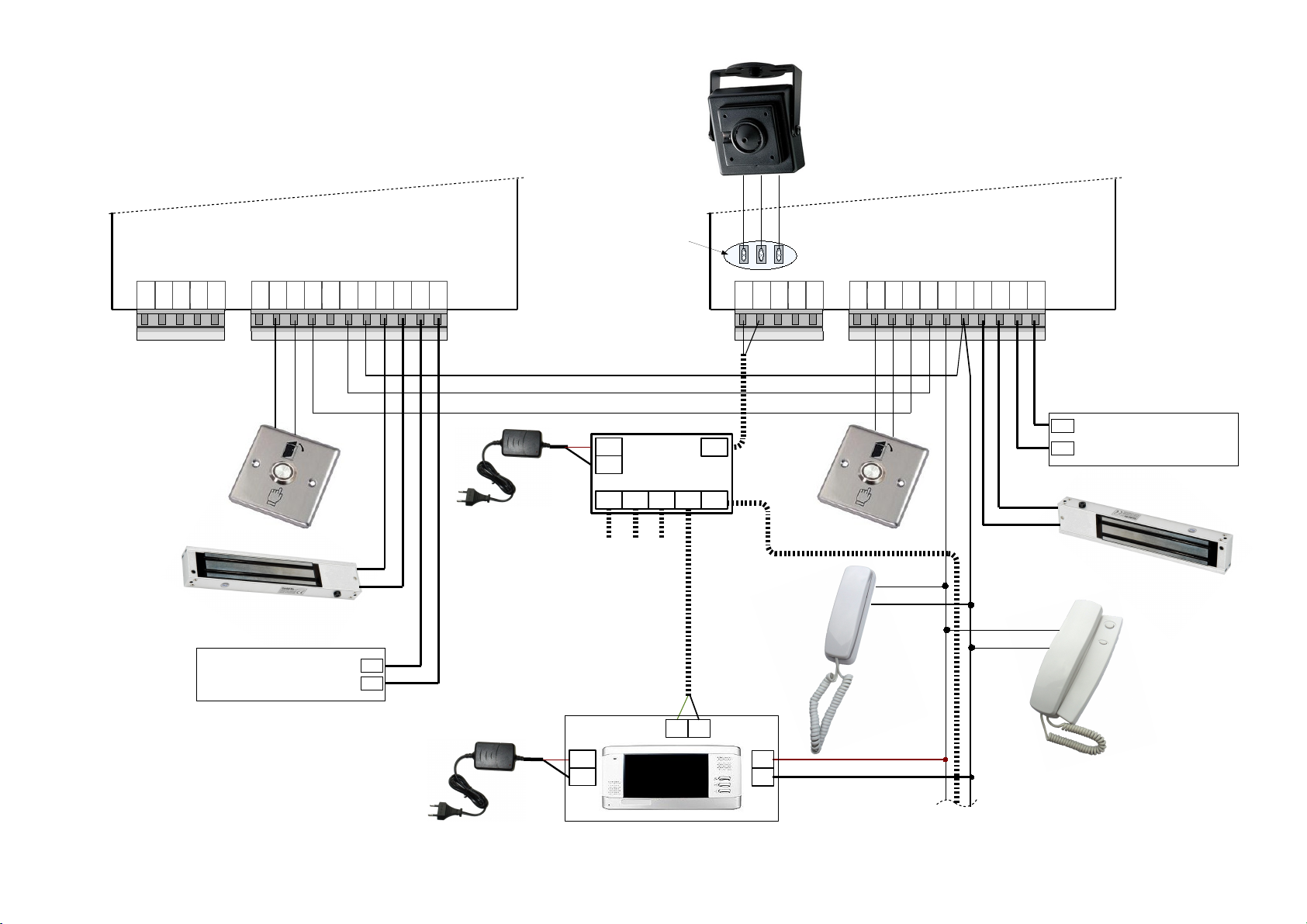
Important: intercom connecting to the network is recommended to connect the call through a network
extender panels that protect the call panel of Electromagnetic pulse interference and remove the impulse
line(fig. 11)
Fig. 11 Intercom connection through a network extender
5.1. Introduction to Net configurations
L – Low Level (Slave) doorphone. To this doorphone should be connected handsets line. In this doorphone are
saved main settings, user keys and codes.
H – High Level (Master) doorphone. This doorphone interacts with L doorphone and through it calls to L doorphone
connected handset. H doorphone also asks L doorphone for programmed keys and codes to decide whether to
open the H doorphone controlled doors.
To check selected doorphone Net type, following key sequence needs to be entered:
*1003#
following info will be shown on display:
[(doorphone type). (active Net type, if any)]
[doorphone ID number]
Example:
[L.nt2] – L type doorphone. NET2 type Net configuration
[ 102] – L doorphone ID = 102
possible H values (1-255)
33
Page 36

DD-5100
possible L values (1-9999)
5.2. Ways to connect DD5100 to Network (Net types)
5.2.1. NET1
In this configuration, at one end L type doorphone (max handset count = 255) and at least one H type
doorphone at other end are used. In order to use more than one H type doorphone, H type doorphones needs to be
connected over Network modules, which output should be connected to L type doorphone input, as shown in fig. 8.
In this configuration use of L type doorphone is identical as with Net function disabled.
Use of H type doorphone from usual configuration differs only in H type doorphone programming menu
limitations. Also in H type doorphone user programming interface is disabled, so users should program their keys
and codes in L type doorphone.
5.2.2. NET2
In this Net configuration more than one L type doorphone (handset count could be more than 255) and at
least one H type doorphone could be used. As in NET1 case to connect to network more than one H type
doorphone, connect them through network adapter as shown in fig. 8.
In this configuration use of L type doorphone is identical as with Net function disabled.
To call to L type doorphone connected handset from H type doorphone, first ID of interested L type
doorphone should be entered, then “Enter” and then the address, as usual. The same holds for keys and codes – in
order to open doors at H type doorphone, code should be entered or key placed after ID of interested L type
doorphone was entered.
How it works:
Call: first enter ID of that L type doorphone, to which handset of interested apartment is connected, then press *
(star), enter number of interested apartment and press “Enter”.
To enter Your code, first enter ID of L type doorphone, connected to Your apartment, then press * (star), enter
apartment address, then again * (star) and then enter Your code, press “Enter” to proceed. Codes are stored in L
type doorphones, so prior use they must be there.
To open doors using Your key, You should do the following: enter ID of L type doorphone, connected to your
apartment, then press * (star), now You can place Your Key on the reader.
5.2.3. NET3
In this Net configuration the same wiring diagram as in NET2 configuration is used. The difference is in
programming and use.
There is no need to enter ID of L type doorphone. When You want to call, enter code or place Your key at the
H type doorphone. H type doorphone with Net3 configuration knows through which L type doorphone interact,
because entered address fall into address range of only one L type doorphone. Obviously address ranges in L type
doorphones should be set correctly to not alias. As well as in NET2 configuration, in NET3 configuration all used L
type doorphones should be added to H type doorphone list. In case You are interacting with L type doorphone, not
added to the list, H type doorphone display will show error [L-Err ] and requested command, won't be executed.
5.3. Network configuration
a) Select network configuration menu from main menu [7.nEt],
b) select first option to enable network configuration [1.SEt],
c) You can reset Net configuration by selecting [2.rSt.nEt].
It is recommended to do Net configurations reset prior configuration:
[7.nEt] > > [2.rSt.nEt] > > [rSt?] > > [donE].
5.3.1. Net configuration examples
Example 1: let's configure L type doorphone for NET2 type network, ID=102:
please do following in programming menu:
[7.nEt] > > [1.SEt] > > [2.nt2] > > [2.L-SEt] > > [id-] > (enter ID (e.g.
L=102)) > > [done]
34
ENTER ENTER ENTER
ENTER ENTER ENTER ENTER
ENTER
Page 37

When doorphone is programmed as L type, structure of menu [7.nEt] changes:
[1.Edit-L] – here current ID could be changed,
[2.rSt.nEt] – network configuration reset.
Example 2: let's configure H type doorphone for Net2 type network, ID=1:
please do following in programming menu:
[7.nEt] > > [1.SEt] > > [2.nt2] > > [2.H-SEt] > > [id-] > ( enter ID (e.g.
H=1)) > > [done]
When doorphone is programmed as H type, structure of menu [7.nEt] changes:
[1.Add-L] – here L type doorphones, connected to network, are added to H type doorphone list,
[2.Edit-H] – here current ID of H type doorphone could be changed,
[3.rSt.nEt] – network configuration reset.
For H type doorphone, those L type doorphones, which is connected to, needs to be specified. Here's how its done:
[7.nEt] > > [1.Add-L] > > [id-] > (enter ID of L type doorphone, used in Net (e.g. L=102)) >
> [done]
5.4. Error codes
[bEr1] – BUS line is shorted. This error is shown only on H type doorphone display. If this happens, doorphone will
open doors every 5 min.
[bEr2] – Presence impulse wasn't received.
[bEr3] – Error in strobing, unknown bit (0 or 1).
[bEr4] – Communication was interrupted or time out.
[bEr5] – Read error - unknown data byte was read.
[bEr6] – Read error – ACK wasn't received at the end of transmission.
Chapter 6. Error, its identification and troubleshooting
Door phone DD-5100 graphically indicates the main errors. Graphical codes and descriptions of errors, fixed
by a door phone are presented in table 5. In case of Er2-Er5 errors, doors have been unlocked every 5 minutes
automatically. In case of Er-1 error, calls to audio handsets fail, but doors could be unlocked by door unlock code or
using electronic identificators.
Table 5: Error indication and description
Error code Possible reason
Er-1 Short circuit of handsets connection line
Er-2 Breakdown of a keyboard, seized button or damaged keyboard
Er-3 Short circuit of TM key reader
Er-4, Er-5 Error/breakdown of system internal data link
Troubleshooting:
• Er-1: switch off a door phone power supply, disconnect handsets connection line wires and switch power
supply on. In case a door phone does not show error Er-1, check receiver line on the matter of short circuit
or breakdown. In case error mark appears, demount door phone module and present it to service
workshops.
• Er-2: inspect the keyboard carefully on the matter of physical deformation or damages; check whether no
button is seized. In case there aren’t any of the mentioned features, demount door phone module and
present it to service workshops.
• Er-3: clean TM reader in bottom part of door phone module. Stored dust, water, ice or snow could disturb
system operation. In case error mark appears, demount door phone module and present it to service
workshops
35
ENTER ENTER ENTER ENTER
ENTER
ENTER ENTER
ENTER
Page 38

DD-5100
• Er-4, Er-5: restart the system – switch off the door phone power supply and switch it on again. In case error
mark appears, demount module and present it to service workshops.
36
Page 39

User Manual
NOTE. Each flat is delivered with an appropriate manufacturer PIN code – 1234. Change it, otherwise doors
unlock code and new identificator programming function are unavailable.
1. How to use a door phone:
For connection with a subscriber enter his/her flat number (from 1 to 9999) and press ENTER (otherwise
call will be started automatically after 3 sec). Should a mistake appear or for canceling your call press
CANCEL.
Conversation starts upon subscriber’s, whom you are calling to, answer. During the conversation the subscriber could
unlock the doors using a button on audio handset.
Door unlock delay time is programmed during system installation and does not depend on duration of pressing the
unlock button.
Unlock button functions only within a handset, the call was addresses to, and only in 2 sec after subscriber’s answer.
Duration of a call and a conversation is limited to 1 min and 2 min accordingly. After this term finishes, the system
returns to duty mode.
In case a door was unlocked with your PIN code, a handset will shortly peep 3 times.
Handset’s switch on/off button allow to switch the receiver off.
2. Entering from outside
There are two ways of unlocking a door externally:
• Using TM identificator *
Attach TM key to a reader. If the key is suitable (added to a door phone memory**), the door unlocks. A
rank number of your key and a note “OPEN” appear on a display shortly with a sound signal. In case an
identificator is related to a flat, a sound signal (informing on door unlock using an electronic key) will be
sent to an handset.
• Using RFID identificator *
Attach RFID identificator to a door phone display ( reader antenna is mounted within) . If the identificator is
suitable (added to a door phone memory**), the door unlocks. A rank number of the identificator and a note
“OPEN” appear on a display shortly with a sound signal. In case an identificator is related to a flat, a sound
signal (informing on door unlock using an electronic key) will be sent to an handset.
• Entering a door unlock code
A door unlock code consists from a flat number ID, a keyboard symbol “*” and an individual 4-digits code
(XXXX)-ID*XXXX. For 4-digits code programming see “Set/change users door unlock code”, page 24, or
User’s Manual, below. After entering a right code using a keyboard, the door unlocks. A note “OPEN”
appears on a display with a sound signal of the door phone and an additional sound signal (informing on
door unlock using individual code, related to the flat) will be sent to an audio receiver.
• Doors could be unlocked by the person you are calling to during the conversation
In order to come indoors, a person (a guest) could call to any flat. During the conversation other person by
the handset has a possibility to unlock the door*** and let the guest in. to unlock the door is possible after 2
sec from the beginning of the conversation. For unlock the door, press a button within the handset without
hang up. Door could be unlocked using the handset, a call is addressed to, during the conversational
session only.
3. Internal door unlock
To unlock the door from inside the building press an unlock button, placed indoors, near the door.
4. Changing of user’s PIN code: NOTE. Each flat is delivered with an appropriate factory PIN code – 1234. Change it, otherwise doors
unlock by code is unavailable.
For changing PIN code two persons are necessary: one staying outdoors near a outdoor panel, other – indoors by
the handset.
1. Enter a flat number, press and wait till a person indoors answers.
2. Press and hold . A person indoors should press a door unlock button for three times (each second).
3. Four dashes will be shown on a display. Enter an old (or factory) PIN .
4. A word “PIN” flashes and four dashes are shown on a display. Enter a new PIN.
37
ENTER
Page 40

DD-5100
If made a mistake, press and start the procedure over. If all steps are performed correctly, the PIN code will
be changed.
5. Programming of new identificators
NOTE. This function is unavailable in case factory PIN code is not changed. The System will ask to change
a factory code first and then programming of identificators becomes available.
Two persons are necessary to program new identificators: one staying outdoors near a call panel, other – indoors
by a handset.
1. Enter a flat number, press and wait till a person indoors answers.
2. Press and hold . A person indoors should press a door unlock button for three times (each second).
3. Four dashes will be shown on a display. Enter PIN code.
4. A new key list number will be shown on a display. Attach a new identificator to the reader. It will be
programmed. In case of attaching an old key, the system peeps two times without re-programming.
New keys should be programmed one by one separately. In order to program several keys, repeat the procedure
several times. Should a mistake appear, press CANCEL and start the procedure from the beginning.
* DD-5100T – door phone with TM reader, DD-5100R – door phone with TM and RFID readers.
** Ways of entering identificators to a door phone memory are described in the cl ause “Add a new identificators”, page 22 or
“User’s Manual”, above.
*** A possibility to unlock the door using a handset could be limited by programming (See “Disable a user according to ID“, Page
28).
38
CANCEL
ENTER
 Loading...