

Page 1
6/28/2005 www.DigitalAquatics.com
i
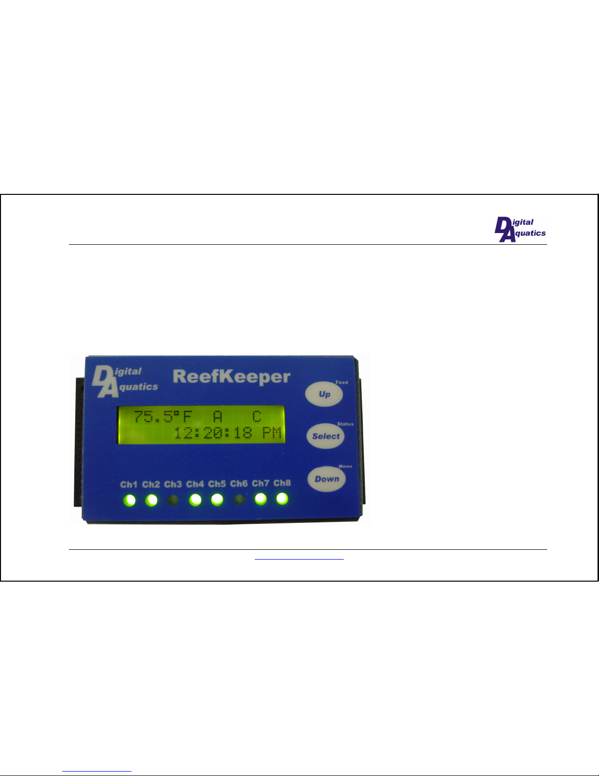
ReefKeeper
Last Revised:
4/5/2005
Digital Aquatics, LLC
Page 2
www.DigitalAquatics.com 6/28/2005
2
2005 Digital Aquatics, LLC. All rights reserving, no part of this manual may be reproduced, copied, transmitted,
disseminated or stored in any storage medium, for any purpose without the express written permission of Digital
Aquatics, LLC. Digital Aquatics hereby grants permission to download a single copy of this manual and of any revision
to this manual onto a hard drive or other electronic storage medium to be viewed for personal use, provided that such
electronic or printed copy of this manual or revision must contain the complete text of this copyright notice and provided
further that any unauthorized commercial distribution of this manual or any revision hereto is strictly prohibited.
Information in this document is subject to change without notice. Digital Aquatics reserves the right to change or
improve its products and to make changes in the content without obligation to notify any person or organization of such
changes. Visit the Digital Aquatics website (
www.DigitalAquatics.com) for current updates and supplemental
information concerning the use and operation of this and other Digital Aquatics products.
Page 3
6/28/2005 www.DigitalAquatics.com
3
Table of Contents
Table of Contents.......................................................... 3
Introduction 4
About this manual......................................................... 4
Product Information 5
Remote Display ............................................................ 5
Power Controller........................................................... 5
Temperature Probe ....................................................... 5
Installation 6
Power Controller Installation........................................ 6
Remote Display Installation ......................................... 6
Temperature Probe Installation..................................... 6
Menu system and User Interaction 6
Overview ...................................................................... 6
Operation ...................................................................... 6
Feed Mode Hotkey ................................................6
Status Hotkey.........................................................6
Night Mode............................................................6
Setup Channels ......................................................6
Setup Wavemaker..................................................6
Setup Temp............................................................6
Feed Duration........................................................ 6
Set Time ................................................................ 6
Appendix 6
Troubleshooting ............................................................ 6
Limited Warranty.......................................................... 6
Service Details ...................................................... 6
Page 4
www.DigitalAquatics.com 6/28/2005
4
INTRODUCTION
About this manual
It is strongly recommended that you read the entire manual before attempting to utilize the ReefKeeper for actual
aquarium control.
The latest version of this manual may be downloaded from our website at
www.DigitalAquatics.com.
Page 5

6/28/2005 www.DigitalAquatics.com
5
PRODUCT INFORMATION
This section gives you a brief overview of the components of your ReefKeeper.
Remote Display
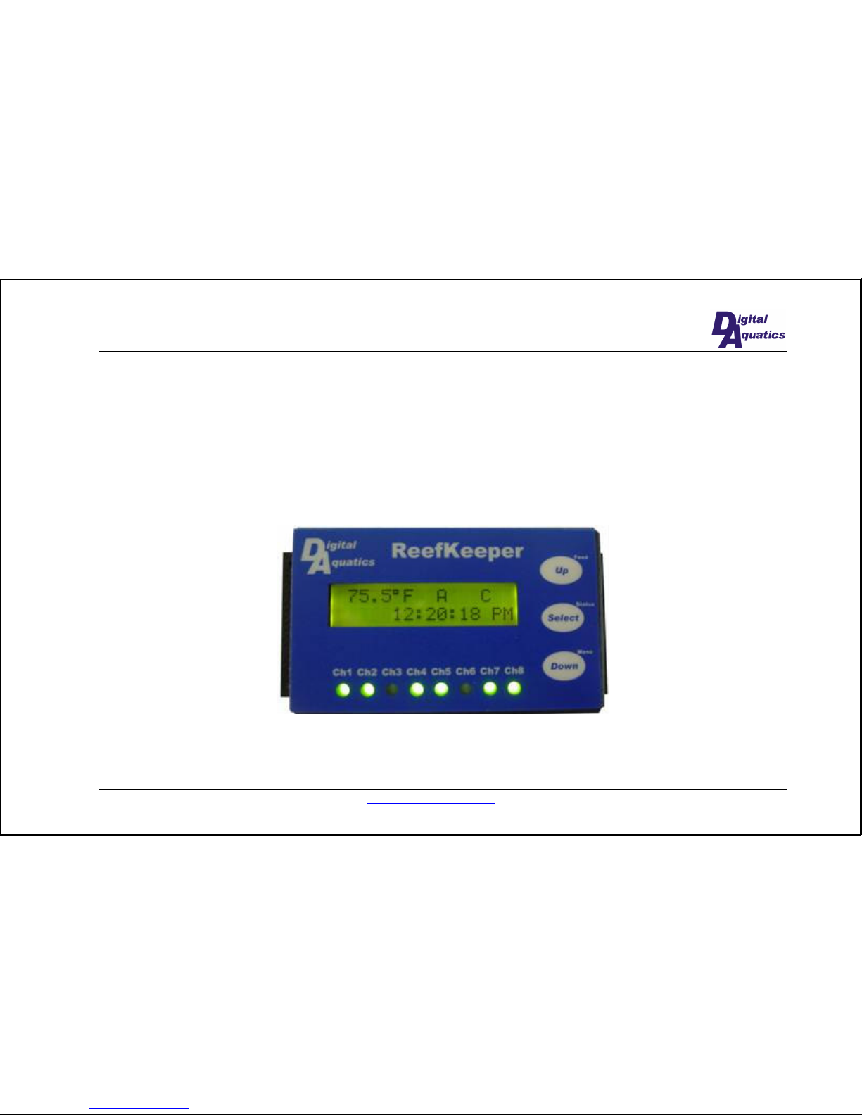
• Eight LEDs along the bottom of the face plate correspond to the eight available channels on the power
controller, indicating which channels are currently turned on.
• Three buttons along the right allow you to configure your ReefKeeper as well as enter Feed Mode and view the
night/day mode status.
• The remote display receives its power via the cable connected to the power controller. In the event of a power
failure, a built-in battery allows the clock and settings to be preserved.
Power Controller
• The power controller looks like a power strip and plugs into a 3 prong wall socket.
• Each of the eight channels can be configured to run any of the ReefKeeper functions.
• Each channel can handle no more than 6 Amps; the entire unit can handle no more than 15 Amps.
Temperature Probe
• The temperature probe plugs into the power controller via the 6 pin connector located on the side of the box.
• Once calibrated, the probe is accurate to +/- 0.2 degrees Fahrenheit.
Page 6
www.DigitalAquatics.com 6/28/2005
6
INSTALLATION
Power Controller Installation
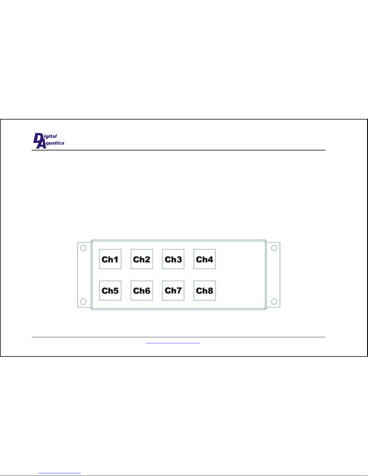
The power controller should be mounted in or around your aquarium cabinet close to a source of power. The power cable
connected to the power controller is 6 feet long; plan distance from an AC wall plug accordingly, do not use extension
cords or splitters to power the ReefKeeper. There are four mounting holes, two on each side of the module. Use these to
mount the power controller in a convenient location within 5 feet of where you would like to mount the remote display
and within 6 feet of where you would like to install the water temperature probe.
When running any wires to the ReefKeeper, be sure to use drip loops so the water does not damage the ReefKeeper..
Page 7
6/28/2005 www.DigitalAquatics.com
7
Remote Display Installation
The remote display may be mounted on the face of your aquarium cabinet or other convenient location. It can also be
mounted flush to a cabinet, giving it a more finished appearance. If you would like to mount it flush, make a rectangular
cutout in your cabinet. Place the front of the module through this hole from behind the cabinet surface. Install four wood
screws to secure the device (make sure screws are the correct length so they don’t go completely through the front of the
cabinetry). Notice that the cable can be oriented straight out the back of the box to accommodate this mounting option.
Now route the cable to the power controller and plug it into the larger of the two receptacles located on the side.
Page 8

www.DigitalAquatics.com 6/28/2005
8
Temperature Probe Installation
• Plug the temperature probe plug into the connector jack on the power controller.
• Route the temperature probe cable through convenient locations and insert it into your tank or sump reservoir.
• For best results, ensure that the end of the temperature probe is at least 6 inches below the surface of the water
in your tank.
Page 9
6/28/2005 www.DigitalAquatics.com
9
MENU SYSTEM AND USER INTERACTION
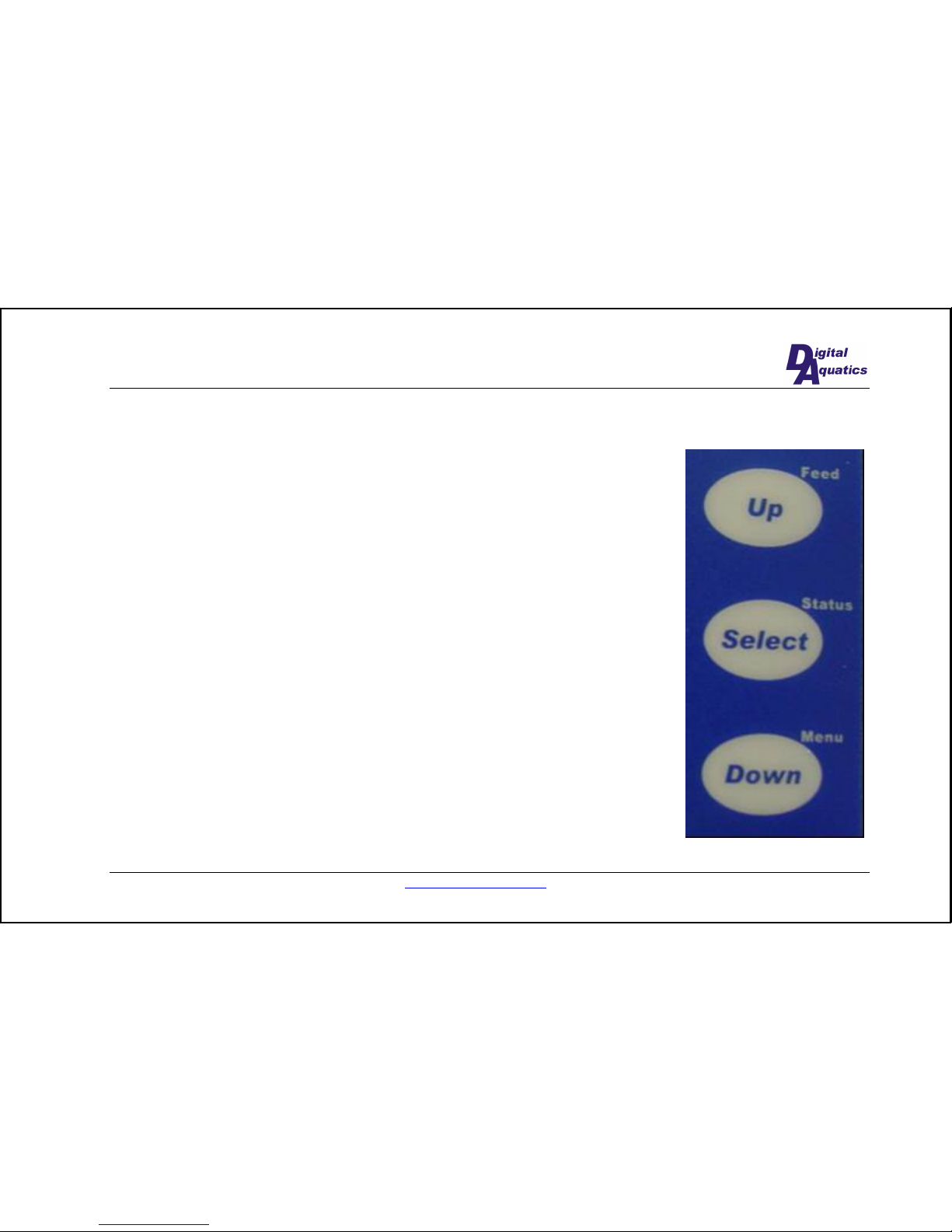
The menu system for the ReefKeeper is designed to provide quick access to commonly
used functions. All user input takes place via the 3 buttons at the right of the front panel
of the ReefKeeper. When the screen is displaying the normal status display, pressing the
bottom button (the “Menu” hotkey) will enter the menu system.
The overview below gives you a guide to the basics of operating the menu system. The
operation section provides a more detailed look at each of the functions that can be
accessed via the menu system.
Page 10
www.DigitalAquatics.com 6/28/2005
10
Overview
The ReefKeeper menu system is designed to be as easy-to-navigate as possible. The
following is a look at the general operation of the menu system. After reading this
section, you should be comfortable with basic configuration of your ReefKeeper.
The following few points will give you a basic understanding of the menu system,
allowing you to better understand the more in-depth
Operation section below.
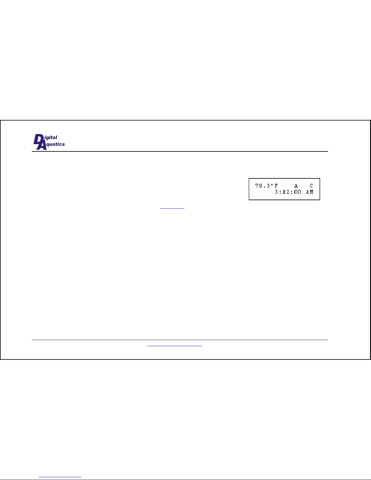
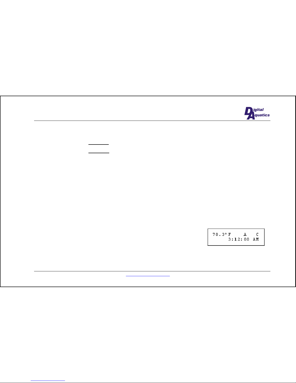
• When in normal operation the display will be showing a status screen containing the temperature, time, and the
currently active wavemaker cycles. This screen looks something like the diagram shown here.
• The currently selected menu item will be blinking. In the main menu flow, two items are shown at a time.
• The menu system operates as a hierarchy. When you press select to make a menu selection, you will be shown
the next level down in the hierarchy.
• When changing values (setting the clock, wavemaker cycle time, etc), press and hold either the Up or Down
button to change values at a faster rate, allowing you to quickly reach the desired value.
• When in the main menu or any of the submenus, if you do not press any button for 10 seconds, the display will
revert back to the normal operating screen.
Operation
This section will guide you through each of main menu selections and their sub-menus. In addition to the main menu
system, there are two hotkey menus which can be accessed when the remote display is in its normal status display.
Page 11
6/28/2005 www.DigitalAquatics.com
11
When you enter the menu system by pressing the Down button, the display presents the first two lines of the menu
system. The top line, Setup Channels, will be blinking, indicating that it is the selected item. Pressing the Select button
will take to you the channel setup submenu. Pressing down will highlight the second item on the display, Setup
Wavemaker. Pressing Up will scroll the display down, selecting Set Time. Each of the 5 main submenus and the 2
hotkey menus will be dealt with below.
Feed Mode Hotkey
When you press the Feed Mode hotkey (the Up button, from the normal operating screen), the system will enter Feed
Mode. While in Feed Mode, all sump pumps and powerheads turn off. This prevents food from being swept away during
feedings which causes unnecessary bio load on your system. The length of time that Feed Mode takes is configurable in
the
Feed Duration section. Feed duration can be set to any amount of time between 1 and 99 minutes, in 1 minute
increments.
Status Hotkey
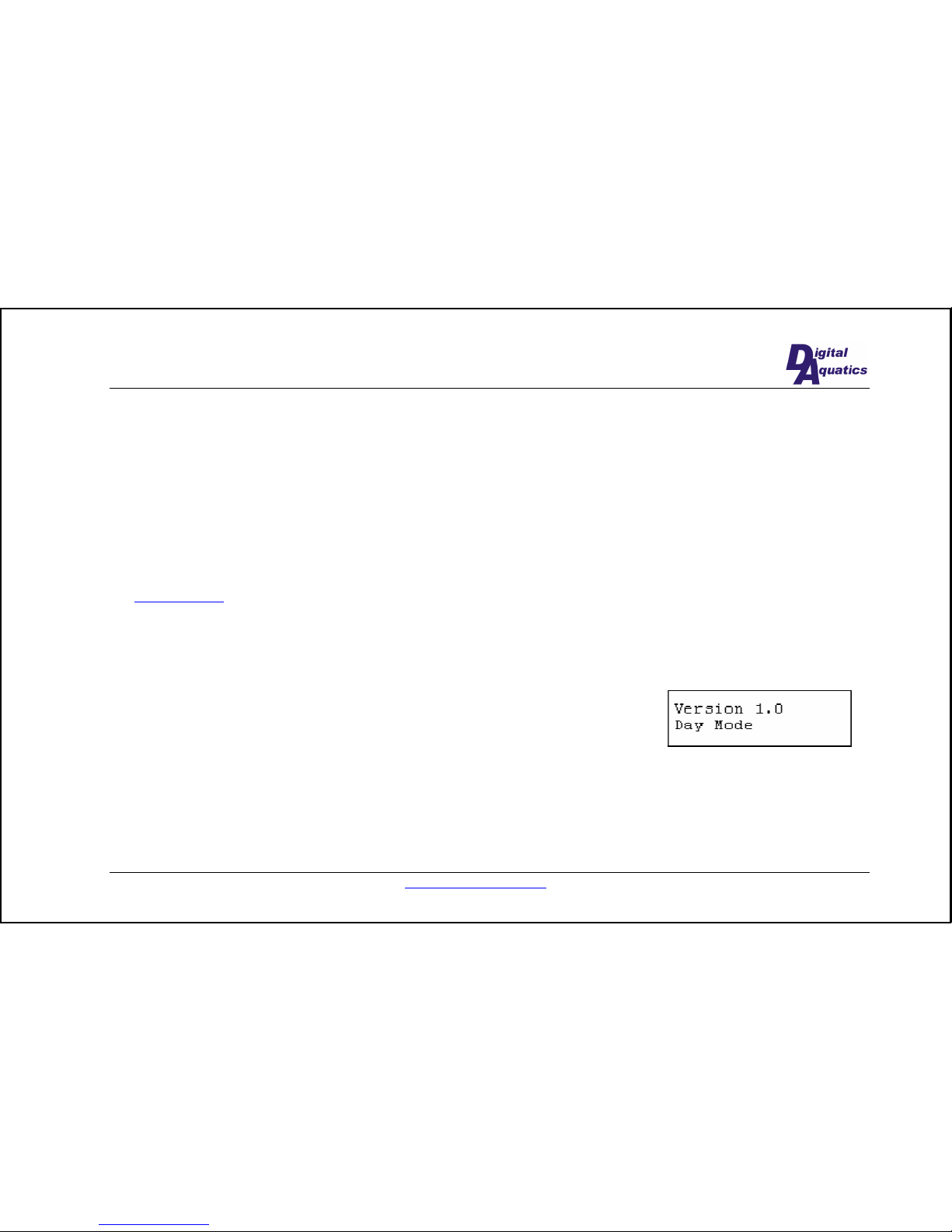
When you press the Status hotkey (the Select button, from the normal operating screen), the Status screen is displayed.
The status screen looks like the example shown here. It provides you with the
version of software that your ReefKeeper is currently running and the Day/Night
Mode status.
Night Mode
Night mode occurs when all the lights are off based on the configuration of the light channels. During night mode the
powerheads that are configured to be off turn off and the A/B and C cycle times double.
Page 12
www.DigitalAquatics.com 6/28/2005
12
Setup Channels
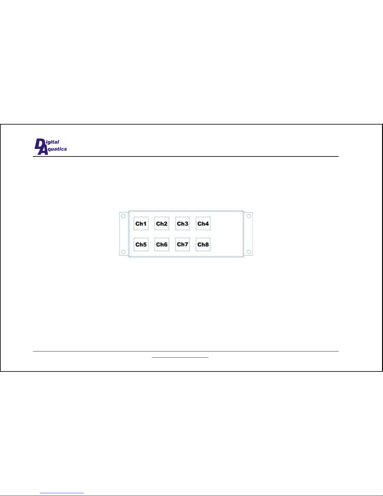
If you would like to reset all 8 channels to their factory-programmed default values, press the Up and Down buttons
simultaneously. You will be presented with a confirmation screen asking if you would like to erase your changes to the
channel configuration and revert to the defaults. Push the Up or Down button to select Yes or No and then press Select to
make your choice.
You may configure any of the 8 channels to perform any of the following functions:
•
Light (metal halide or other type)
•
Sump Pump
•
Powerhead
•
Heater
•
Fan/Chiller
•
Always on
•
Always off
Page 13
6/28/2005 www.DigitalAquatics.com
13
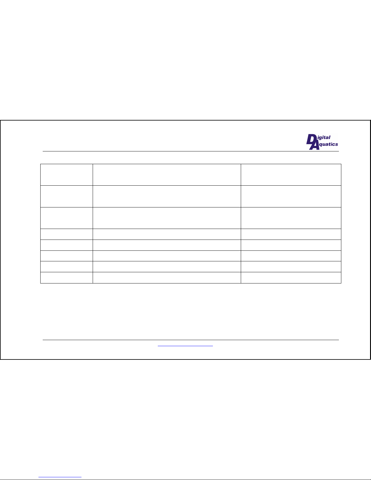
By default, the channels are configured as follows. You, of course, may change any channel to be any function.
Channel 1 Other light Turn on: 8 AM
Turn off: 8 PM
Channel 2 Metal halide light Turn on: 9 AM
Turn off: 7 PM
Channel 3 Fan/Chiller Turn on temp: 82 ºF
Turn off temp 80 ºF
Channel 4 Heater Cut off temp: 78 ºF
Channel 5 Powerhead Cycle A – 6 minute cycle
Channel 6 Powerhead Cycle B – 6 minute cycle
Channel 7 Powerhead Cycle C – 8 minute cycle
Channel 8 Sump Pump
To change any given channel’s configuration, enter the menu system by pressing the Menu hotkey and proceeding with
the following instructions.
While in the menu system, ensure that the Setup Channels command is blinking, indicating that it is highlighted. If it is
not, press the Up or Down button until it is. Press the Select button to enter the Setup Channels submenu. Now, Channel
1 is selected. Press Up or Down until the desired channel is blinking (if you would like to return to the main menu, press
Page 14
www.DigitalAquatics.com 6/28/2005
14
Up or Down until “Back” is blinking; then press the Select button). Now, choose the desired function for that channel
and press Select.
If you set the channel to control a light
, select whether the light is a metal halide or other type of light. If it is a Metal
Halide, the ReefKeeper will ensure that it has time to cool down after a power loss before turning back on. After making
your selection, set the time that you would like the light to turn on. Use the Select button to make each selection for
hours and minutes. Then, set the time you would like to have the light turn off. Pressing Select will return you to the
main channel selection menu. Note that if the ReefKeeper has been power cycled within the last 15 minutes any metal
halide channel will be off until a full 15 minutes have passed. The LEDs are blinking during this time to indicate that
they will be turned on after the 15 minutes has passed.
If you set the channel to be a sump pump
the ReefKeeper will automatically turn the sump pump off during feed mode.
If you set the channel to be a powerhead
, choose which wavemaker cycle you would like the powerhead to be a part of.
For more information, see the
Setup Wavemaker section below. After making your wavemaker cycle selection, specify
whether you want that particular pump to be on or off during night mode.
If you set the channel to be a heater
, you will need to specify the temperature at which you would like to have the heater
be shut off. When using the heater function, set the thermostat on your heater to no more than two degrees above the
threshold temperature on the ReefKeeper. This will allow redundant protection from a single-point failure.
If you set the channel to be a fan/chiller
, you will need to specify the temperatures at which you would like to have the
fan/chiller turn on and turn off. In this way, the fan/chiller function allows you to set your desired hysteresis. When the
water heats up to the turn-on temperature, the fan/chiller turns on. As the water then cools down, the fan/chiller will turn
off at the turn-off temperature. It will then not turn on until it reaches the upper turn-on temperature. This prevents the
fan/chiller from cycling rapidly when the water is hovering around the set point. You may, however set the turn-on and
turn-off temperatures to be equal if you would like the water temperature to maintain at a given temperature regardless of
the rate at which your fan or chiller cycles. When using the fan/chiller function, set the thermostat on your fan or chiller
Page 15
6/28/2005 www.DigitalAquatics.com
15
to no more than three degrees below the fan/chiller turn-off temperature on the ReefKeeper. This will allow redundant
protection from a single-point failure.
If you set the channel to be always on
, it will act as regular power outlet, with no switching.
If you set the channel to be always off
, there will be no power to that channel. It is recommended that you set unused
channels to this setting.
Setup Wavemaker
Every channel that is set to be a powerhead is associated with one cycle: A, B, or C. The A and B cycles alternate at the
set interval. The C cycle turns on and off at the set interval but is independent of the A and B cycles.
In the Setup Wavemaker menu, you must first set the Cycle A/B time. This is the amount of time that cycle A will be on
while cycle B is off and vice versa. You may set this time to any value between 20 seconds and 4 hours. Once you have
made your selection, you must set the Cycle C time. This is the amount of time that cycle C will be on and off for in
succession. You may set this time to any value between 20 seconds and 2 hours.
Night mode occurs when all the lights are off based on the configuration of the light channels. During night mode the
powerheads that are configured to be off turn off and A/B and C cycle times double.
The currently active wavemaker cycles are displayed on screen, as shown at right
with the ‘A’ and ‘C’.
Page 16
www.DigitalAquatics.com 6/28/2005
16
Setup Temp
When you enter the Setup Temp menu you will have the choice of displaying temperature in either Fahrenheit or Celsius.
Press Select to make your selection. You are now presented with the temperature adjustment section. This section shows
you the temperature that the probe is currently reading. You may calibrate the temperature displayed to increase the
accuracy of the ReefKeeper by pressing Up or Down. Make your selection and you will be returned to the main menu.
Feed Duration
In this menu, you may specify the length of time Feed Mode will last. This value may be set to a value between 1 minute
and 99 minutes. Make your selection and you will be returned to the main menu.
Set Time
When in this submenu, simply adjust the hours and minutes to correspond to the current time. When you exit this menu,
the seconds are reset to 0.
Page 17
6/28/2005 www.DigitalAquatics.com
17
APPENDIX
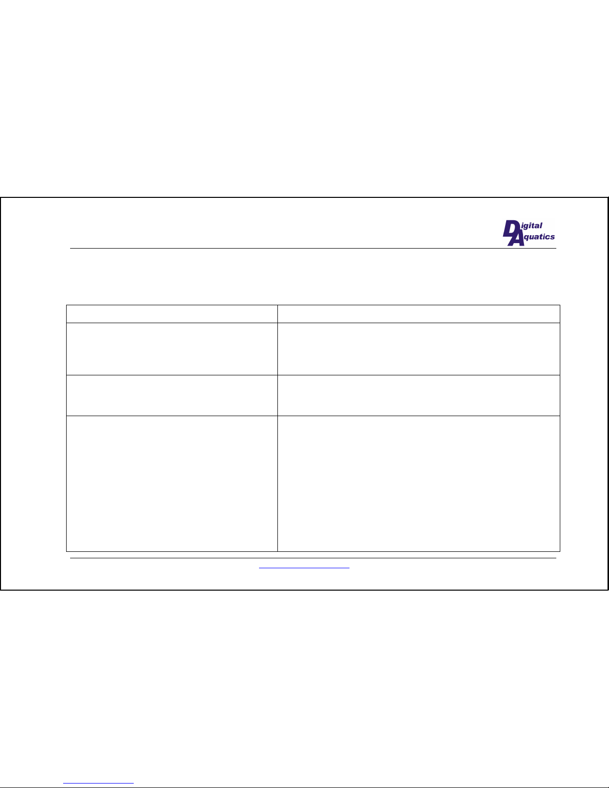
Troubleshooting
Problem Solution
The temperature display says “Probe removed” Ensure that your temperature probe is securely plugged into the
power controller. If it is plugged in securely, and the message is still
displayed, the probe may be faulty. Contact Digital Aquatics
technical support at [email protected]
The temperature is inaccurate Enter the “Setup Temp” menu. In the “Calibrate Temp” section,
adjust the temperature up or down until it displays the correct water
temperature.
The fuse inside the ReefKeeper has blown To replace the fuse do the following steps:
•
Acquire a replacement 5mm x 20mm 15A fast fuse. P/N
GMA-15A (Digital Aquatics sells replacement fuses)
•
Unplug the ReefKeeper! (very important)
•
Remove the screws from the power controller and separate
the two pieces. Notice the fuse in a holder on the circuit
board.
•
Remove the fuse from the holder and replace it with the
new fuse.
•
Place the two box pieces back together and secure screws.
Page 18
www.DigitalAquatics.com 6/28/2005
18
Limited Warranty
Digital Aquatics LLC warrants this product to be free from defects in materials and workmanship for one year from date
of shipment. Digital Aquatics will, at its sole discretion, repair or replace any components that fail in normal use. The
customer is responsible for any transportation costs. This warranty does not cover failures due to abuse, misuse, accident,
improper installation or unauthorized alteration or repairs.
THE WARRANTIES AND REMEDIES CONTAINED HEREIN ARE EXCLUSIVE, AND IN LIEU OF ALL OTHER
WARRANTIES EXPRESSED OR IMPLIED, INCLUDING ANY LIABILITY ARISING UNDER WARRANTY OF
MERCHANTABILITY OR FITNESS FOR A PARTICULAR PURPOSE, STATUTORY OR OTHERWISE. THIS
WARRANTY GIVES YOU SPECIFIC LEGAL RIGHTS, WHICH MAY VARY FROM STATE TO STATE.
IN NO EVENT SHALL DIGITAL AQUATICS BE LIABLE FOR ANY INCIDENTAL, SPECIAL, INDIRECT OR
CONSEQUENTIAL DAMAGES, WHETHER RESULTING FROM THE USE, MISUSE OR INABILITY TO USE
THIS PRODUCT OR FROM DEFECTS IN THE PRODUCT. SOME STATES DO NOT ALLOW THE EXCLUSION
OF INCIDENTAL OR CONSEQUENTIAL DAMAGES, SO THE ABOVE LIMITATIONS MAY NOT APPLY TO
YOU.
Service Details
Should you experience difficulty with your ReefKeeper, please contact [email protected]. A customer service
representative will contact you regarding your problem.
 Loading...