

Page 1
860-00201-00 Rev 0.9
November 2013
Installation Guide
Professional Digital Vehicle Video System and
Live Streaming Gateway
Copyright © 2013, Digital Ally, Inc. All Rights Reserved. This publication may not be reproduced, stored in a retrieval system, or
transmitted in whole or part in any form or by any means electronic, mechanical, recording, photocopying, or in any other manner
without the prior written approval of Digital Ally, Inc.
Page 2

Digital In-Car Video System
Installation Guide
On behalf of the Digital Ally team, I want to thank you for this order. We appreciate the trust and
confidence you have shown us.
We will strive to do everything we can to provide you with the best products, support and customer
service. Please know we have a team of engineers, sales, manufacturing, customer service,
accounting, technicians and support personnel who work to provide the excellent customer
experience and satisfaction you demand and of which is the cornerstone of our business.
Below are a few comments and suggestions before you get started with the installation of your
Digital Ally DVM-Live system:
•
The DVM-LiVE is designed to be easily installed into virtually any make or model of
vehicle.
•
Please check the packing list against the items enclosed to make sure you have received all
the items.
•
Pictures of the various components of the system are shown throughout this guide to assist
you.
•
Please refer to the DVM-Live Operation Guide for operating instructions. You can print this
document off of the CD you received with your order.
•
The default passwords to access the DVM can be located on page 4-1 of this document.
•
A system diagram is provided on page 2-5 of this document, and wiring connections chart is
provided on page 2-6.
If you need any help, have any questions, or just want to provide some comments, please feel free to
contact us and we will be happy to assist you. We are located in the Kansas City metro area.
Best regards,
Stanton Ross, CEO
Digital Ally, Inc.
9705 Loiret Blvd
Lenexa, KS 66219
Ph: 800-440-4947 or 913-814-7774
Fax: 913-814-7775
Email: support@digitalallyinc.com
Website: www.digitalallyinc.com
Copyright © 2013, Digital Ally, Inc. All Rights Reserved. This publication may not be reproduced, stored in a retrieval system, or
transmitted in whole or part in any form or by any means electronic, mechanical, recording, photocopying, or in any other manner
without the prior written approval of Digital Ally, Inc.
Page 3

Table of Contents
SECTION - 1: BEFORE YOU BEGIN ............................................................................................................1-1
TOOLS NEEDED ....................................................................................................................................................1-1
CAUTIONS AND NOTES .........................................................................................................................................1-1
SECTION - 2: PARTS LISTS AND SYSTEM DIAGRAMS ..........................................................................2-1
STANDARD PARTS KIT ..........................................................................................................................................2-1
OPTIONAL PARTS LIST .........................................................................................................................................2-2
DVM LAYOUT CONFIGURATION...........................................................................................................................2-4
SYSTEM DIAGRAM ...............................................................................................................................................2-5
WIRING CONNECTIONS CHART .............................................................................................................................2-6
SECTION - 3: INSTALLATION INSTRUCTIONS .......................................................................................3-1
STEP 1: FACTORY MIRROR REMOVAL ...........................................................................................................3-1
Screw Mount Rearview Mirror Removal ......................................................................................................3-1
Wedge (screw-less) Mount Rearview Mirror Removal .................................................................................3-1
Cam Lock Rearview Mirror Removal ...........................................................................................................3-1
STEP 2: DVM INSTALLATION .......................................................................................................................3-2
STEP 3: INTERFACE BOX INSTALLATION .......................................................................................................3-3
Interface Box ................................................................................................................................................3-3
Mount the IO box ..........................................................................................................................................3-3
DVM to Interface Box Cable Installation .....................................................................................................3-3
STEP 4: POWER, GROUND, AND INPUT SENSOR CONNECTIONS .....................................................................3-4
Power Cable Installation..............................................................................................................................3-4
I/O Cable Installation ...................................................................................................................................3-4
Determine the Device Trigger(s) Signal Level .............................................................................................3-5
Output Alarm Trigger ...................................................................................................................................3-6
RJ45 to Terminal Connector Adapter (optional) ..........................................................................................3-7
Siren Adapter Interface ................................................................................................................................3-7
STEP 5: WIRELESS MIC INSTALLATION .........................................................................................................3-7
DWM800 Wireless Microphone Cable Installation ......................................................................................3-8
STEP 6: FRONT CAMERA INSTALLATION ......................................................................................................3-9
STEP 7: GPS ANTENNA ................................................................................................................................3-9
STEP 8: WI-FI ANTENNA ..............................................................................................................................3-9
STEP 9: LIVE STREAMING GATEWAY ............................................................................................................3-9
Video Connections ........................................................................................................................................3-9
Power Connections ....................................................................................................................................3-10
Antenna Connections ..................................................................................................................................3-10
SECTION - 4: TESTING THE INSTALLATION ..........................................................................................4-1
INITIAL POWER UP ...............................................................................................................................................4-1
RECORD AN EVENT...............................................................................................................................................4-1
VIEWING THE BACKUP CAMERA (IF INSTALLED) .................................................................................................4-1
INPUT SENSOR & WIRELESS MICROPHONE TESTS ................................................................................................4-1
SECTION - 5: SUPPORT ..................................................................................................................................5-1
HOW TO RESET THE DVM-LIVE SYSTEM ................................................................................................ ............5-1
BASIC TROUBLESHOOTING ...................................................................................................................................5-1
SECTION - 6: CONTACT INFORMATION ..................................................................................................6-1
SECTION - 7: INTERFACE BOX SENSOR WORKSHEET .......................................................................7-1
Copyright © 2013 Digital Ally, Inc. i
Page 4

Digital Ally, Inc. | Before you Begin
1-1
Section - 1: Before you Begin
This document references the installation of the DVM-LiVE system, external cameras, and the cabling
harnesses.
Tools Needed
#2 Phillips head screwdriver
#20 Torx screwdriver or bit
1/8" (4 mm) flat-blade screwdriver
Digital Volt Meter
Tie wraps
Cautions and Notes
Please read and follow the instructions and precautions in this installation guide when installing DVMLiVE product.
• For assistance, a qualified installation technician or mechanic should be consulted.
• Do not use excessive force when removing the mirror from the windshield. The mirror mounting
plate may become separated from the windshield and/or the windshield may break if excessive
force is used. If you are unfamiliar with rearview mirror removal seek professional assistance.
• Do not route wiring and cabling over sharp metal edges where they may become damaged or
cut.
• To prevent electrical shorts or breakage in the wiring and cabling, do not allow wiring and
cabling to be pinched behind trim pieces, panels, or other physical objects.
• Do not run wires or cables in areas where they may become damaged by heat from the engine
or the exhaust system.
• Do not install any DVM components or wiring in the deployment path of the air bag(s).
• When installing the cables or making wire connections, it is recommended you leave a little
‘slack’ in the cable connections to allow for service loops and for movement of the mirror so the
connections do not get pulled or accidentally disconnected.
• Where possible, avoid running cables parallel to other wiring and/or antenna coax that may be
installed in the vehicle.
• Where possible, do not leave excessive cable above the headliner. We recommend at least 2
feet of distance between our cabling and that of other systems which may carry a signal for
transmit and/or receive
Page 5
Digital Ally, Inc. | Parts Lists and System Diagrams
2-1
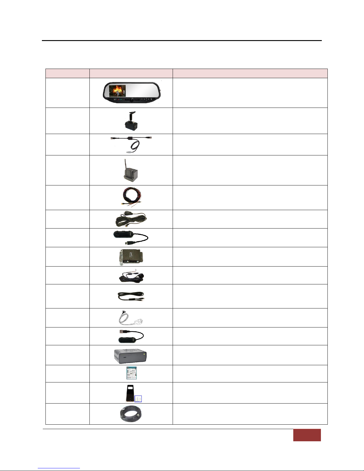
Part Number
Description
001-00049-32
DVM-Live Package, 32GB
566-00127-00
Camera, CAM-10XC, 10x with built-in controls
008-01443-00
Cable, DVM-LiVE to 10xC Camera and BNC
002-05095-00
Wireless Mic, DVM-LiVE System
008-01455-00
Cable, DWM-800 to DVM-LiVE
004-09058-00
Cable, Back Seat Microphone to DWM-LiVE, 20ft.
2.5mm plug
001-00010-00
Wi-Fi Assembly
006-08210-00
IO box (model IFE-20)
008-01388-00
Vehicle Power to IO box Cable 3.1m (10.1ft.)
008-01386-00
IO Box to DVM Power Cable 2.5m (8.0ft.)
008-01362-00
IO Box RJ45 Sensor Cable 7.6m (25ft.)
008-01410-00
GPS Module
001-00500-00
2 Channel Live Video Streaming Module
860-00202-00
Quick Reference Guide
006-08255-00
Visor Mount For external front Camera
008-01419-25
BNC cable 25ft (2)
Section - 2: Parts Lists and System Diagrams
Standard Parts Kit
Page 6
Digital Ally, Inc. | Parts Lists and System Diagrams
2-2
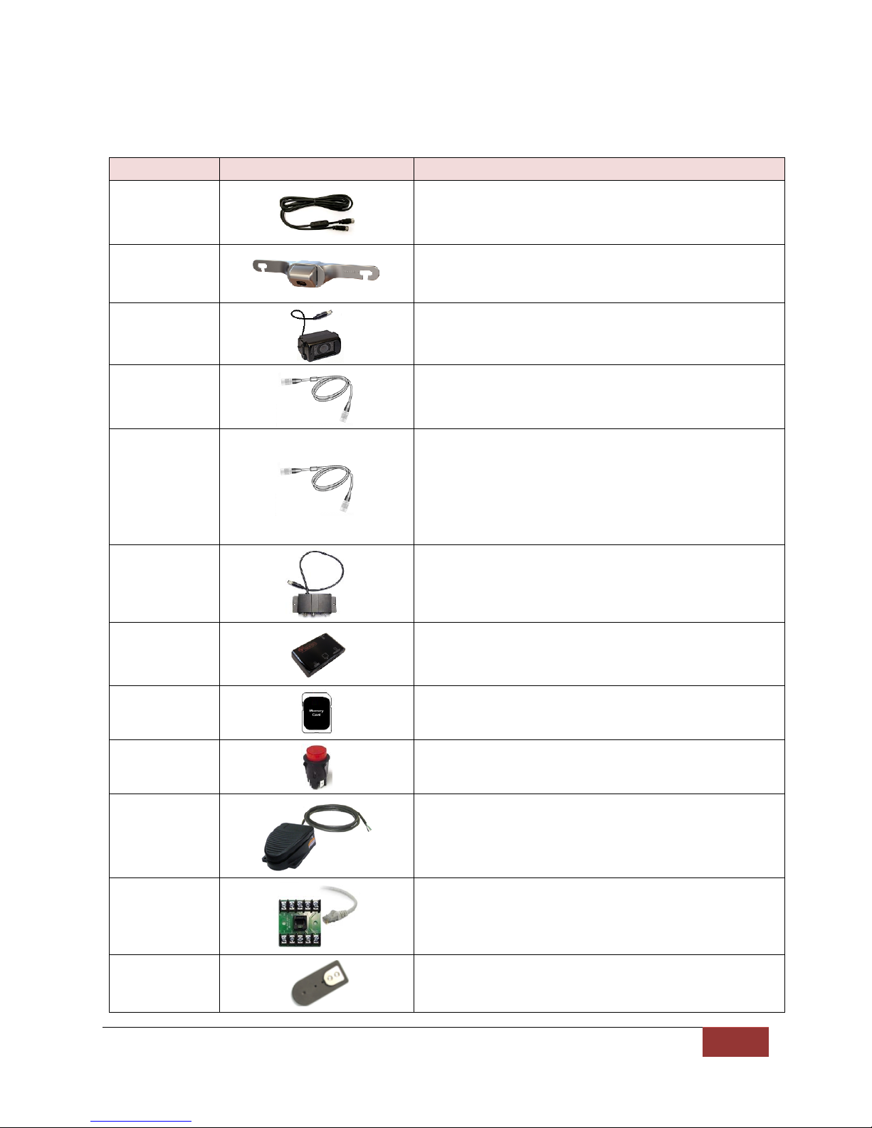
Part Number
Description
008-01386-01
008-01386-02
008-01386-03
IO Box to DVM Power Cable 4.6m (15ft.)
IO Box to DVM Power Cable 6.1m (20.0ft.)
IO Box to DVM Power Cable 8.1m (26.5ft.)
566-00038-00
License Plate Backup Camera ( includes mounting
screws, pigtail cable, center mount & side mount
license plate brackets)
566-00040-00
Aux Surface Mount Backup Camera Normal Image
(includes mounting h/w & mounting bracket)
008-01390-01
Backup Camera Cable 12.2m (40.0ft.)
008-01382-00
008-01382-01
008-01382-02
008-01382-03
Backup Camera 25ft Extension Cable
Backup Camera 40ft Extension Cable
Backup Camera 60ft Extension Cable
Backup Camera 15ft Extension Cable
006-08193-00
Assembly, DVM-250 Camera Switch Box
002-00028-00
SD Card Reader
363-00050-00
32GB External SD card
740-00388-00
Panel Mount Remote Activation Switch
740-00399-00
Footswitch, Maintained (18/2AWG, 6ft, bare leads)
002-05107-00
Terminal Block Kit (for input sensors)
002-05030-00
Drop Mount Adapter
Optional Parts List
Page 7
Digital Ally, Inc. | Parts Lists and System Diagrams
2-3
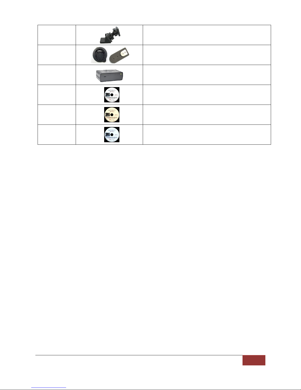
002-05102-00
Kit, Big Ball Mount Adapter
002-05112-00
Windshield Mount Adapter Kit, Dodge Charger
001-00501-00
4 Channel Live Video Streaming Module
860-00151-00
VuVault™ Stand Alone Software DVD
860-00152-00
VuVault™ Server/Client Software DVD
860-00153-00
VuVault™ Enterprise Software DVD
Page 8
Digital Ally, Inc. | Parts Lists and System Diagrams
2-4
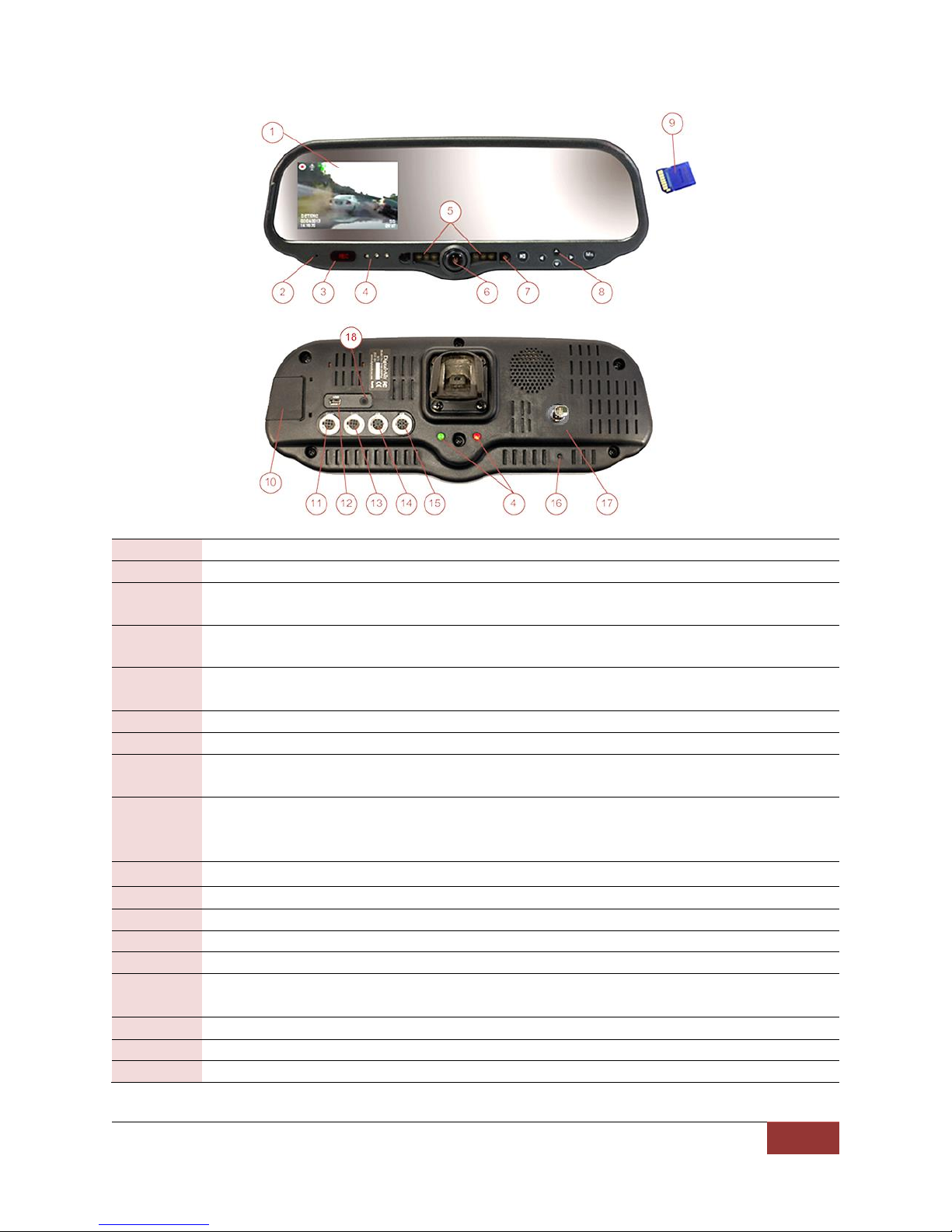
1
LCD Display: Used for viewing video.
2
Internal microphone: Records audio from the passenger compartment.
3
Manual Record key: This key is used to start/stop a manual event recording when
pressed.
4
Status Indicators (Passenger facing & Road facing): These visible indicators give the
operator feedback on the operational status of the DVM.
5
Infrared Illuminators: Automatically provides Infrared illumination for the passenger
facing camera during low light conditions.
6
Passenger facing camera: Records video of the vehicle passenger area
7
Ambient Light Sensor: Senses ambient light to automatically adjust LCD brightness
8
Menu and Playback Buttons: Used to navigate the DVM menus, play back videos, and log
into the system.
9
External SD Card (optional): An optional external SD card can be installed behind the
external SD door. The SD card is installed at a slight angle and positioned with the
connector pads as shown above.
10
External SD door: Provides access to the external SD card.
11
External Camera 1 Port: An external camera can be connected to the DVM with this port.
12
USB Port: For data transfer and Wi-Fi download
13
External Camera 2 Port: Reserved for future use
14
External GPS Port: The supplied GPS antenna is connected here.
15
Power port: This port is used to provide power to the DVM or can be used to attach the
interface box to the system.
16
Reset Button: Used to perform a hard reset of the system.
17
BNC Video Output: Connects to the Streaming Gateway video input.
18
External Audio Input: The DWM-LiVE audio cable is connected here.
DVM Layout Configuration
Page 9

Digital Ally, Inc. | Parts Lists and System Diagrams
2-5
DWM-800 Wireless Microphone
& Charger (page 3-10)
GPS Antenna
Input Sensor Connections
(See page 2-6 and 3-5)
DVM-LiVE™
Rear Panel
Interface Box (page 3-3)
I/O Box to DVM Cable
BTR800 Cable
(page 3-7)
Front Camera
DWM800 Wireless
Microphone Connections
(See page 2-6 and 3-8)
Main power cable
connections
(See page 2-6 and 3-4)
Chassis Ground
Live Streaming Gateway
BNC Cable
3G or 4G
Antenna
Front Camera Y Cable
Gateway power cable
connections
(See page 3-10)
Wi-Fi Antenna
BNC Cable
System Diagram
Page 10

Digital Ally, Inc. | Parts Lists and System Diagrams
2-6
Input Signal
Color
Pin #
Description
Main Power Cable (page 3-4)
Battery
Red
1
+12VDC Un-switched Power. REQUIRED. Digital Ally recommends
connecting directly to the engine compartment battery
Ignition
2
+12VDC Switched. +12V power only when ignition is in the ACC or On
position. Ignition is used to cycle the system power on and off.
Ground
Black
3
Chassis Ground. Secure directly to vehicle frame
Input Sensor Cable (page 3-5)
Reverse
Red
1
Connect to reverse gear relay, or reverse light bulb
Emergency Lights
Orange
2
Emergency Light interface. +12VDC when lights are activated. Connect
to light bar controller
Brakes
Blue
3
Connect to brake pedal switch or 3rd brake light. +12VDC when brake is
active
Siren 4
Connect to +12VDC when siren is ON.
Sensor 5
5
Configurable input sensor
Mic Trigger Out
Green
6
Connect to Green wire of DWM800 Wireless Microphone Cable
Mic Trigger In
Brown
7
Connect to Brown wire of DWM800 Wireless Microphone Cable
Ground
Black
8
Chassis Ground
DWM800 Wireless Microphone Cable (page 3-8)
Battery
Red
1
+12VDC Un-switched Power. Digital Ally recommends connecting
directly to the engine compartment battery
Ground
Black
2
Chassis Ground
Mic Trigger Out
Green
3
Connect to Green wire of Input Sensor Cable
Mic Trigger In
Brown
4
Connect to Brown wire of Input Sensor Cable
Remote Accessory
Out
Violet
5
Connect to auxiliary equipment (optional connection)
Wiring Connections Chart
Page 11

Digital Ally, Inc. | Installation Instructions
3-1
Be very careful and do not use excessive force when removing the mirror from the
windshield. The mirror mounting plate may become separated from the windshield
and/or the windshield may break if excessive force is used.
Step 1: Factory Mirror Removal
Section - 3: Installation Instructions
The current factory rearview mirror must be removed from the windshield mounting plate. There are
several versions of mirror mounting systems. Below are the most common methods of rearview mirror
removal. If you are unfamiliar with rearview mirror removal, seek professional assistance.
Use one of the following methods that match the mirror mounting configuration of your vehicle:
Screw Mount Rearview Mirror Removal
1. Using a Philips screwdriver or #20 Torx bit, loosen the screw in the base of the mirror.
2. After loosening the screw, gently lift upward to slide mirror off of mirror mount.
Wedge (screw-less) Mount Rearview Mirror Removal
1. Using a small 1/8" (4 mm) flat-blade screwdriver, insert the flat end into the opening at the
bottom of the mirror mount next to the windshield.
2. Slide the screwdriver into the center of the mirror mount until resistance is felt.
3. Gently apply a small amount of additional upward force to lift away the locking spring inside the
mount.
4. While still applying upward pressure with the screwdriver, grasp the mirror bracket and wiggle
side to side. Lift the mirror up toward the headliner and off the windshield mount button.
Cam Lock Rearview Mirror Removal
1. With your right hand, grip the mirror and keep it stabilized.
2. With your left hand, grip the base of the factory mount where it meets the glass.
3. Apply a small amount of inward pressure toward the glass and rotate the base clockwise.
4. The spring loaded factory mount should release from the windshield puck. See picture below.
Page 12

Digital Ally, Inc. | Installation Instructions
3-2
In some vehicles, the position of the manufacturer’s windshield mounting plate may
not allow for proper rearview DVM adjustment for some individuals, especially when
the vehicle is equipped with an overhead console and/or interior emergency lighting.
In these cases, the mounting plate included with the DVM-LiVE package must be
glued to the windshield in a location that will allow proper adjustment. Loctite
#03346 glue is recommended. Please follow instructions on their package
The shielding strap must be connected to a metal surface of the vehicle chassis to
prevent EMI and RF interference. Failure to properly connect the shielding strap may
cause system operation issues.
Step 2: DVM Installation
1. Slide the new rearview DVM (Digital Video Mirror) onto the existing windshield mounting plate
and secure your DVM to the vehicle windshield. For some 2011 - 2013 Dodge vehicles, attach
and orientate the optional adapter to factory windshield as shown. Use Loctite™ to secure the
adapter to the factory windshield mount. If needed, attach optional drop down bracket as
shown.
2. Use a #20 Torx screw driver to tighten the mounting screw.
3. Adjust the viewing angle for the rearview mirror.
4. The unconnected end of the DVM shielding strap must be securely connected to the vehicle
chassis. The strap should be routed and attached to the metal structure above the windshield.
5. If the optional Big Ball Mount Kit (002-05102-00) was purchased, attach to the DVM as shown
below. Do not over tighten the hex locking screws in the middle of the Big Ball mount or the
DVM may break off the windshield when adjusted. Follow the instructions included in the kit.
6. Remove the protective film covering from the
internal Passenger facing camera.
Page 13

Digital Ally, Inc. | Installation Instructions
3-3
Do not place the IO box directly on floorboard or mount it in areas where it could
be exposed to moisture such as air conditioner condensation, accidental liquid
spills, rain, snow, mud, or other elements that could be tracked into the vehicle
from outside the vehicle.
Do not place the IO box in an area that will subject the unit to excessive heat such
as a transmission tunnel or engine firewall.
The shielding strap must be connected to a metal surface of the vehicle chassis to
prevent electrical interference. Failure to properly connect the shielding strap may
cause system operation issues.
Step 3: Interface Box Installation
Interface Box
The Interface Box (IO Box) must be securely mounted on a solid area of the
vehicle structure in a moisture free location where it can be easily accessed.
Possible mounting locations include:
• Under the dash on the passenger side.
• Behind the kick panel on the passenger side (or driver side).
• Screwed into the transmission tunnel sheet metal below the dash. On some vehicles this may
not be possible due to extreme heat radiated from the transmission.
Screwed into the exterior of the center console.
• Under the seat on some SUV-type vehicles.
• Behind a panel on the right hand side of the dash (nearest to the door).
Mount the IO box
1. Use the IO Box to DVM cable as a gauge to estimate an appropriate location for mounting the IO
box.
2. Once a suitable mounting location has been identified for the IO box, verify that the shielding
strap can be securely connected to the metal surface of the vehicle chassis. If the shielding strap
does not reach a suitable metal surface, reposition the IO box
appropriately.
3. Secure the unconnected end of the shielding strap to the vehicle chassis.
DVM to Interface Box Cable Installation
1. Plug the connector of the IO box to DVM cable into the back of the
DVM.
2. Leaving slack in the cable at the mirror mounting bracket for DVM
adjustment, begin routing the cable from the DVM under the front
edge of the headliner down the windshield pillar towards the
mounting location for the IO box. To conceal the cable, it may be necessary to loosen the sun
visor mounting bracket and/or other trim pieces to allow the cable to be tucked in behind the
headliner.
Page 14

Digital Ally, Inc. | Installation Instructions
3-4
Do not route wiring and cabling over sharp metal edge. Avoid running the cable
parallel to other wiring and/or antenna coax from other equipment in the vehicle. To
prevent electrical shorts or breakage in the wiring and cabling, do not allow wiring
and cabling to be pinched behind trim pieces, panels, or other physical objects.
Step 4: Power, Ground, and Input Sensor
Connections
Pin
Connection
Wire Color
1
POWER
Connect to +12vdc battery terminal
RED
2
IGNITION
Connect to +12Vdc ignition switch
3
GROUND
Vehicle Chassis
BLACK
Figure 3-4: Power Connections
Main Power Cable I/O Cable
3. Secure the cable using Velcro or standard tie wraps as required.
4. Plug the remaining end of the DVM cable into the IO box.
Power Cable Installation
1. Plug the connector of the Vehicle Power cable into the IO box.
2. Route the cable to a suitable location for electrical connection.
3. Remove 4 to 5 inches of the outer jacket at the bare end of the power cable.
Separate the braided shield from the individual conductors, attach an electrical terminal to the
end of the braided shield, and attach the terminal to the chassis of the vehicle.
4. Connect the Red wire of the power cable to the vehicle +12Vdc battery terminal and the Black
wire of this power cable directly to the vehicle’s chassis. It is required that the power wire be
tied in with DVM interface box connection with no obstructions to battery such as a cutoff
switch or charge guard system.
5. Connect the White wire to the ignition switch where +12vdc is only present when the vehicle
ignition key is in the ON position.
6. Secure the cable and the inline fuse housing using Velcro or standard tie wraps as required. The
cable contains a filter to help minimize unwanted RF noise and 3 amp fuse.
7. Re-connect the cable to the connector on the back of the DVM.
I/O Cable Installation
The IO Box provides multi-purpose sensor inputs that allow external devices to trigger an event
record in the mirror. It also provides an Output Alarm to turn devices on or off when an event
trigger occurs. The output alarm is also used to trigger the RMT-800 wireless microphone during a
record event. Common external sensors include; emergency lights, siren, brake pedal, turn signal
indicators, reverse gear, covert foot-switch, or door sensors.
Page 15

Digital Ally, Inc. | Installation Instructions
3-5
Pin
Sensor
Wire Color
1
REVERSE
Reverse Gear Sensor
RED
2
LIGHTS
Connect to +12Vdc Light Bar output
ORANGE
3
BRAKES
Connect to +12Vdc Brake switch
BLUE
4
SIREN
Connect to +12Vdc siren output
5
Sensor #5
Configurable input
6
MIC trigger out
Connect to GREEN wire of DWM-800
harness (see figure 3-10)
GREEN
7
Mic Trigger in
Connect to BROWN wire of DWM-800
harness (see figure 3-10)
BROWN
8
GND
Connect to vehicle chassis
BLACK
Figure 3-5: Input Sensor Connections
Determine the Device Trigger(s) Signal Level
For the administrator to configure each of the six (6) multi-purpose input sensors, the signaling from
the external device must be found and documented. Determine the signaling of each external
device that will be used and document the signal information on the Sensor Worksheet that has
been provided on page 7-1.
1. Position RJ-45 end of the sensor cable near the IO box RJ-45 jack, but do not plug it into the IO box
just yet.
2. Leaving a service loop for connection to the IO box, begin routing the un-terminated end of the
sensor cable to the desired location in the vehicle for connection for each of the input sensor
devices.
3. Cut off excess cable as required, and strip the cable jacket from the un-terminated end of the
sensor cable to access the individual wires.
4. Use figure 3-5 below for wiring connections to the sensor cable and connect the external devices
to the appropriate wire of the RJ-45 sensor cable.
5. The GREEN and BROWN wires are reserved for the DWM-800 wireless microphone system.
Connect the wires as shown in figure 3-6 to ensure microphone activation functions correctly. Use
butt splice connectors to attach the green and brown wires.
6. When all external devices have been connected, plug the RJ45 into the jack labeled “SENS A” on
the IO box.
Page 16

Digital Ally, Inc. | Installation Instructions
3-6
The device, relay, and fuse are optional customer provided items. Be sure to select a relay
which can handle the power requirements of your device.
+12V, (2A max.)
To Vehicle Battery
To Pin 7 of the IF Box
SENS A connector cable
(BROWN wire)
85 86
30
87a
87
Device
GNDPower IN
NC
Fuse 2A Fast Blow
+12V, (2A max.)
To Vehicle Battery
To Pin 7 of the IF Box
SENS A connector cable
(BROWN wire)
85 86
30
87a
87
Device
GNDPower IN
NC
Fuse: 2A Fast Blow
I/O harness
BTR800
harness
Figure 3-6: Input Sensor Connections (cont)
Connect green and brown wires
I/O Box
DWM800
wireless
microphone
Output Alarm Trigger
In addition to activating the DWM-800 wireless microphone, A DVM-LiVE can be configured to
activate or deactivate an auxiliary device when an event record begins. Below is a general outline
showing how the Output Alarm Trigger can be wired using an interposing relay.
Example wiring diagrams:
1. Activate during Event Recording: To activate low power devices when an Event Trigger is active,
the example diagram below shows how to connect it to the IO box. When the Output alarm is
active the relay will be energized and the device will be powered on. If the Output Alarm is not
active, the relay will not be energized and the device will not be powered.
2. De-Activate during Event Recording: To de-activate low power devices when an Event Trigger is
active, the example diagram below shows how to connect it to the IO box. When the Output
alarm is active the relay will be energized and the device will not be powered. If the Output
Alarm is not active, the relay will not be energized and the device will be powered on.
Page 17

Digital Ally, Inc. | Installation Instructions
3-7
Step 5: Wireless Mic Installation
Terminal Block
DVM IO box
RJ45 to Terminal Connector Adapter (optional)
If heavier gauge and jacket wiring is required, an optional terminal connector
adapter kit (P/N 002-05107-00) is available for purchase from Digital Ally.
The adapter allows customer provided wire to be used for wiring sensors
from the vehicle to the IO box. For more information and installation
instructions, refer to the Terminal Block Kit Installation Instructions included
with the kit.
Siren Adapter Interface
If an acceptable DC output cannot be obtained from the siren controller, the optional siren adapter
interface (Digital Ally P/N 006-0050) can be used to connect the siren speaker to the interface box.
Follow the diagram below to install the siren interface.
When using the siren adapter, the input sensor must be configured for a High to Low,
Standard Threshold within the VuVault device configuration.
1. Attach the mounting bracket to the back of the BTR (base
transceiver cradle); the assembly can then be mounted at your
preferred location, such as the side of the center console.
2. Attached the antenna. If you are using the optional external
In-Car Microphone, connect it to the BTR In-Car Microphone
jack and route the microphone to your preferred location in
your system. The typical mounting location for the external incar microphone is in the rear seat area along the headliner &
below the weather strip.
Page 18

Digital Ally, Inc. | Installation Instructions
3-8
Connection
Wire Color
POWER
Connect to +12vdc battery terminal
RED
GND
Connect to vehicle chassis
BLACK
REMOTE ACCESSORY OUT
Connect to auxiliary equipment
(optional connection)
VIOLET
MIC trigger out
Connect to GREEN wire of DWM-800
harness (see figure 3-6)
GREEN
MIC trigger in
Connect to BROWN wire of DWM-800
harness (see figure 3-6)
BROWN
Figure 3-8: BTR800 Cable Input Connections
3. Connect the BTR cable assembly to the RJ-45 input on the BTR.
DWM800 Wireless Microphone Cable Installation
Carefully route the BTR800 cable to the back of the DVM. Make the following connections listed in
figure 3-8.
4. Connect the mini a/v jack to the audio input jack on the
back of the DVM. Be sure to leave enough slack in the
cable to allow for movement of the mirror.
Pressing the Emergency button on the wireless
microphone will activate the +12vdc remote accessory
output signal (if connected), but will not trigger a record
event.
Page 19

Digital Ally, Inc. | Installation Instructions
3-9
Step 6: Front Camera Installation
Step 7: GPS Antenna
Step 8: Wi-Fi Antenna
Step 9: Live Streaming Gateway
Front Camera
1. Attach the visor mount through the visor clip and attach front camera to the mounting plate.
2. Attach the camera cable (008-01442-00) to the DVM-LiVE Camera 1 input.
Clean the windshield glass with alcohol. Screw in the GPS antenna to
the port on the back of the DVM. Using the included double-sided tape,
attach the antenna to an unobstructed location on the windshield
below the roofline. Do not place the GPS antenna near any other
vehicle antenna.
Clean the windshield glass with alcohol. Plug the Wi-Fi antenna into the USB
port on the back of the DVM. Using the included double-sided tape, attach
the antenna to an unobstructed location on the windshield below the roofline
away from the GPS antenna.
Please refer to the DVM-LiVE Operation Guide for configuration of the
wireless transfer feature.
Video Connections
1. Determine a suitable location for the live streaming gateway. Do
not mount the gateway module in an area exposed to moisture.
2. Attach the front camera pigtail cable to the gateway Vin2 input using a supplied BNC cable.
3. Attach the video output from the rear panel of the DVM-LiVE to the Vin1 input of the streaming
module using a supplied BNC cable.
Page 20

Digital Ally, Inc. | Installation Instructions
3-10
Figure 3-10: gateway video connections
Front camera
Video Gateway
DVM-LiVE
IGNITION BATTERY GROUND
Power Connections
4. Connect Ignition, Battery, and Chassis Ground to the green power connector as shown below.
Antenna Connections
5. Connect the supplied GPS receiver cable to the GPS connector on the
rear of the unit.
6. Place the antenna as high up as possible in the vehicle or on the roof
of the vehicle. Make sure the antenna is horizontal and is facing up
(smaller side up), and attach it in its intended location with doublesided tape. Make sure the antenna is attached securely to the vehicle
so that it will not come loose when the vehicle moves. If possible, place it in a location near the
roofline in which there are no obstructions between it and the sky. DO NOT place the GPS
antenna in close proximity of the other GPS antenna you installed previously in step 7.
7. A cellular modem is required for live video streaming capabilites. Connect your cellular modem
with USB adapter to the USB port. Use a USB extension cord for connecting the cellular modem
to the unit. The modem functions best if it is installed high in the vehicle in an exposed location.
The extension cord should not be longer than about 1.5 meters. Please note that not all cellular
modems are supported. Please contact Digital Ally Technical Support for a list of supported
cellular modems.
Page 21

Digital Ally, Inc. | Testing the Installation
4-1
Initial Power Up
Record an Event
Viewing the Backup Camera (if
installed)
Input Sensor & Wireless
Microphone Tests
Section - 4: Testing the Installation
1. Insert the SD card into the DVM.
2. Turn the vehicle ignition switch to the ON position. The vehicle does not have to be running.
3. The DVM will begin the boot-up process; all 3-LEDs will flash in unison at a 1 second interval
until boot up is complete.
4. Once the boot-up process is complete, the Blue LED will be lit indicating the DVM is powered on,
is ready, and in standby mode.
5. Login to the DVM using the up/down arrows. The default administrator password is 111111, the
default user password is 222222. Press the Ms button to save your entry.
1. Press the RECORD button.
2. The Red status indicator will illuminate to indicate the manual
event is being recorded.
3. After 10 seconds, press the RECORD button to stop the manual
event record.
4. The Red status indicator will extinguish, indicating the DVM has returned to standby mode.
1. Start the vehicle and leave the transmission in Park.
2. Apply the brake and put the transmission into Reverse gear.
3. The LCD monitor will turn on and the live-video from the backup camera will be displayed.
4. If configured as an event trigger, the Red status indicator will illuminate indicating the back-up
event is being recorded.
5. Put the transmission back into Park.
6. The LCD monitor will turn off.
1. Remove the wireless microphone from the charging cradle and turn the power switch ON. The
Green LED should be lit solid.
2. Activate a connected trigger input device (such as emergency lights) to start a recording.
3. The Red status indicator on the DVM will flash to indicate the event is being recorded, and the
Green LED on the wireless microphone should start blinking.
4. Press the record button on the DVM to stop the recording.
5. The Red status indicator will extinguish, indicating the DVM has returned to standby mode.
6. Press the REC button on the wireless microphone. The system should again start to record as
previously in step 3.
7. Press the record button on the DVM to stop the recording. A power down timer will start when
the vehicle’s ignition is turned off.
Page 22

Digital Ally, Inc. | Support
5-1
Symptom
Resolution
System will not power up.
Verify the power cable connector is connected to the back of the
DVM.
Check the power cable fuses located in the in-line fuse housing on
the power cable.
Verify there are no breaks, pinches, or cuts in the wiring or cable
harness.
Check the wiring and voltage levels to the vehicle power and
ignition switch wiring.
All LEDs are flashing rapidly in
unison
DVM is configured to use an external SD card and the SD card is
missing.
The external SD card does not have enough free available storage
for uploading the events from internal memory. Replace the
external SD card with a blank SD card.
DVM powers up but doesn’t
record
Check the LED status indicators and clear accordingly
Reset the system.
DVM powers up and goes
directly to an event record
(Red LED Flashes)
An event record has been triggered from either an internal sensor or
from an IO box:
Disconnect the Sensor Cable RJ-45 connector from the IO box and
reset the DVM. If the problem doesn’t re-occur, check the wiring
from the vehicle to the sensor cable.
Check the DVM configuration parameter values for all internal
sensors and/or IO box sensors.
DVM is unresponsive
Verify the cables and cable connections.
Verify power input voltages to the IO box (page 3-4)
Press the reset button on the back of the DVM.
False Triggering of Event
Recordings
Determine which trigger is causing the false trigger by viewing the
event recording.
The unit can be reconfigured to default settings and enable each
trigger to determine which one is causing the false trigger.
If the Accelerometer is causing false triggering, verify the mirror is
in the normal rearview mirror orientation.
Wireless Microphone does
not trigger the DVM to record
Verify the cable connections on page 3-8. Verify the BTR800 is
receiving power and the microphone is synced to the system.
Verify device configuration in the VuVault software.
Section - 5: Support
How to Reset the DVM-LiVE System
Using a small blunt object such as a small eye-glass screwdriver or a paper
clip, press the reset button on the DVM. The reset button is recessed and
located on the road facing, driver’s side of the housing as shown here.
Basic Troubleshooting
Page 23

Digital Ally, Inc. | Contact Information
6-1
9705 Loiret Blvd
Lenexa, KS USA 66219
Website:
www.digitalallyinc.com
Support E-Mail:
support@digitalallyinc.com
Sales E-Mail:
sales@digitalallyinc.com
Phone:
00-1-913-814-7774
Fax:
00-1-913-814-7775
Sales / Support Toll Free:
00-1-800-440-4947 8am-5pm CST
Section - 6: Contact Information
Page 24

Digital Ally, Inc. | Interface Box Sensor Worksheet
7-1
Section - 7: Interface Box Sensor Worksheet
Date:
DVM Serial #:
Vehicle #:
Description:
Measured DC Voltage
Device Type/Description
(Note IO box input harness wire color used)
Inactive State (Vdc)
Active State (Vdc)
Reverse Gear Signal - RED
(Park)
(Reverse)
Emergency Lights - ORANGE
Brakes - BLUE
Siren - YELLOW
Signal to Input Sensor (administrator use)
Sensor
Wire Color
Connection
Detection Type
Threshold
Sensor #1
RED
Reverse Gear
Low to High
High to Low
Standard
High
Lights
ORANGE
DC output from light bar controller
Low to High
High to Low
Standard
High
Brakes
BLUE
Brake switch or 3rd brake light
Low to High
High to Low
Standard
High
Siren
YELLOW
DC output from siren controller
Low to High
High to Low
Standard
High
Sensor #5
WHITE
Configurable
Low to High
High to Low
Standard
High
Wireless
Microphone
GREEN
MIC trigger out
green wire of DWM-800 harness
RMT Trigger
IN
BROWN
MIC trigger in
brown wire of DWM-800 harness
GND
BLACK
Chassis ground
Installer to complete upper section
Administrator to complete lower section
To configure an input sensor, the signaling of the device must be given to the administrator. Measure the
DC voltages, record the signal levels, and provide the information to the administrator.
Sensor Wiring Assignment
Wiring assignment assigned by administrator
 Loading...