

Digital-Ally DVM-750 Installation Manual
DVM-750 Installation Guide 860-0008-00 Rev C
Digital Ally, Inc |DVM-750 Installation Guide
i
Installation Guide
DVM-750
Digital In-Car Video System
Copyright © 2009-2013, Digital Ally, Inc. All Rights Reserved, Printed in U.S.A. This publication may not
be reproduced, stored in a retrieval system, or transmitted in whole or part in any form or by any means
electronic, mechanical, recording, photocopying, or in any other manner without the prior written approval
of Digital Ally, Inc.

DVM-750 Installation Guide 860-0008-00 Rev C
Digital Ally, Inc |DVM-750 Installation Guide
ii
DVM-750 Digital In-Car Video System
Installation Guide
On behalf of the Digital Ally team, I want to thank you for this order. We appreciate the trust and
confidence you have shown us.
We will strive to do everything we can to provide you with the best products, support and customer
service. Please know we have a team of engineers, sales, manufacturing, customer service,
accounting, technicians and support personnel who work to provide the excellent customer
experience and satisfaction you demand and of which is the cornerstone of our business.
Below are a few comments and suggestions before you get started with the installation of your
Digital Ally DVM-750 system:
•
The DVM-750 is designed to be easily installed into virtually any make or model of
vehicle.
•
Please check the packing list against the items enclosed to make sure you have received all
the items.
•
Pictures of the various components of the system are shown throughout this guide to assist
you.
•
Please refer to the DVM-750 Operation Guide for operating instructions. You can print this
document off of the CD you received with your order, or if you would like us to send you a hard
copy, you can contact us and we will mail you one.
•
The default logins and passwords to access the DVM can be located on page 19 of this
document.
•
The system diagram is provided on page 7 of this document, and a wiring connections chart is
provided on page 17.
If you need any help, have any questions, or just want to provide some comments, please feel free
to contact us and we will be happy to assist you. We are located in the Kansas City metro area.
Best regards,
Stanton Ross, CEO
Digital Ally, Inc.
9705 Loiret Blvd
Lenexa, KS 66219
Ph: 800-440-4947 or 913-814-7774
Fax: 913-814-7775
Email: support@digitalallyinc.com
Website: www.digitalallyinc.com

DVM-750 Installation Guide 860-0008-00 Rev C
Digital Ally, Inc |DVM-750 Installation Guide
iii
Table of Contents
STANDARD LIMITED WARRANTY MODEL DVM-750 .................................................................................... 1
BEFORE YOU BEGIN INSTALLATION ................................................................................................................ 2
PARTS AND ACCESSORIES ................................................................................................................................... 2
DVM-750 Standard Parts List ................................................................................................................................... 2
DVM-750 Optional Parts List ................................................................................................................................... 4
DVM-750 Optional Backup Camera Parts List ......................................................................................................... 5
CAUTIONS & NOTES ............................................................................................................................................... 6
DVM-750 Interface Box Backup Battery .................................................................................................................. 6
SYSTEM DIAGRAM .................................................................................................................................................. 7
SYSTEM INSTALLATION ....................................................................................................................................... 8
Step 1: Factory Mirror Removal .......................................................................................................................... 8
2011-2012 Dodge Charger Rearview Mirror Removal ................................ ................................ ........................ 8
Step 2: Remove Factory Body Trim .................................................................................................................... 8
Step 3: Attach the Big Ball Mount ..................................................................................................................... 10
Step 4: Mirror Connections ................................................................................................................................ 11
Step 5: Camera Installation ................................................................................................................................ 12
Front Camera ..................................................................................................................................................... 12
Rear Seat Camera (optional) .............................................................................................................................. 12
Backup Camera (optional) .................................................................................................................................. 13
Step 6: GPS and Rear Microphone Connections ............................................................................................... 16
Step 7: Power, Ignition, Ground, and Trigger Connections ............................................................................... 16
Wiring Connections Chart .................................................................................................................................. 17
Connecting to the vehicle’s reverse gear ............................................................................................................ 18
Step 8: Mount the Interface Box ........................................................................................................................ 18
Step 9: Wireless Microphone Charging Cradle.................................................................................................. 19
TESTING YOUR INSTALLATION ....................................................................................................................... 19
Insert the CF card .................................................................................................................................................... 19
Post Installation Checklist ....................................................................................................................................... 20
How to Reset the DVM-750 System ....................................................................................................................... 20
TROUBLESHOOTING ............................................................................................................................................ 21
PRODUCT REPAIR ................................................................................................................................................. 22
CONTACT INFORMATION ................................................................................................................................... 22

DVM-750 Installation Guide 860-0008-00 Rev C
Digital Ally, Inc |DVM-750 Installation Guide
1
STANDARD LIMITED WARRANTY
MODEL DVM-750
REAR VIEW MIRROR IN-VEHICLE DIGITAL VIDEO SYSTEM
We warranty that our In-Car Digital Video System, Model DVM-750, will be free from defects in
workmanship and material for a period of 24 months from the date of purchase by the original
purchaser. If any defect is discovered through normal and proper use of the unit during this
period, the defect will be repaired or the unit will be replaced at our factory or at one of our
authorized service centers at no cost to the purchaser. The purchaser must return the defective
unit to the factory or one of our authorized service centers, freight prepaid. We will pay for
shipping charges for the return of the unit.
This warranty applies only to defects in a unit’s internal electronic components and circuitry,
and is void as to units that have been opened without prior authorization, have experienced
unauthorized repairs, or have had unauthorized modifications. This warranty does not cover the
following:
Normal wear and tear on the unit such as batteries, frayed cables or wires, broken
connectors, or scratched or broken cases.
Damage caused by incorrect use of the unit, carelessness, abuse, unauthorized
alterations to the unit, improper storage of the unit or unauthorized service,
installation or repairs made to the unit.
Damage caused by fire, flood, lightning, vandalism, collision, Acts of God, or
other events beyond the reasonable control of Digital Ally, Inc. or the purchaser.
Damage to external parts of the unit such as buttons, microphones, wires, and
cables, etc.
Damage from use of the unit in hostile operating environments.
We reserve the right to charge for repairs to a unit during the warranty period made necessary
because of any of the foregoing causes at our standard rates for repair of units not under
warranty.
The purchaser assumes all risk of use from its purchase and use of the unit. Harmful personal
contact with a unit might occur in the event of violent maneuvers, collisions, or similar
circumstances, even if the unit was properly installed and used. We are not responsible for, and
we specifically disclaim any liability for injury caused by a unit in such circumstances.
THIS WARRANTY IS GIVEN IN LIEU OF ALL OTHER WARRANTIES. THERE ARE NO
WARRANTIES THAT EXTEND BEYOND THIS STATEMENT. ALL IMPLIED WARRANTIES
ARE DISCLAIMED, INCLUDING, WITHOUT LIMITATION, WARRANTIES OF
MERCHANTABILITY, NON-INFRINGEMENT, FITNESS FOR A PARTICULAR PURPOSE,
AND WARRANTIES IMPLIED FROM A COURSE OF DEALING, COURSE OF
PERFORMANCE OR USAGE OF TRADE. THE PURCHASER’S SOLE AND EXCLUSIVE
REMEDY FOR A WARRANTY CLAIM WILL BE THE REPAIR OR REPLACEMENT OF A
UNIT.
DVM-750 Installation Guide 860-0008-00 Rev C
Digital Ally, Inc |DVM-750 Installation Guide
2
Part Number
Image
Description
Quantity
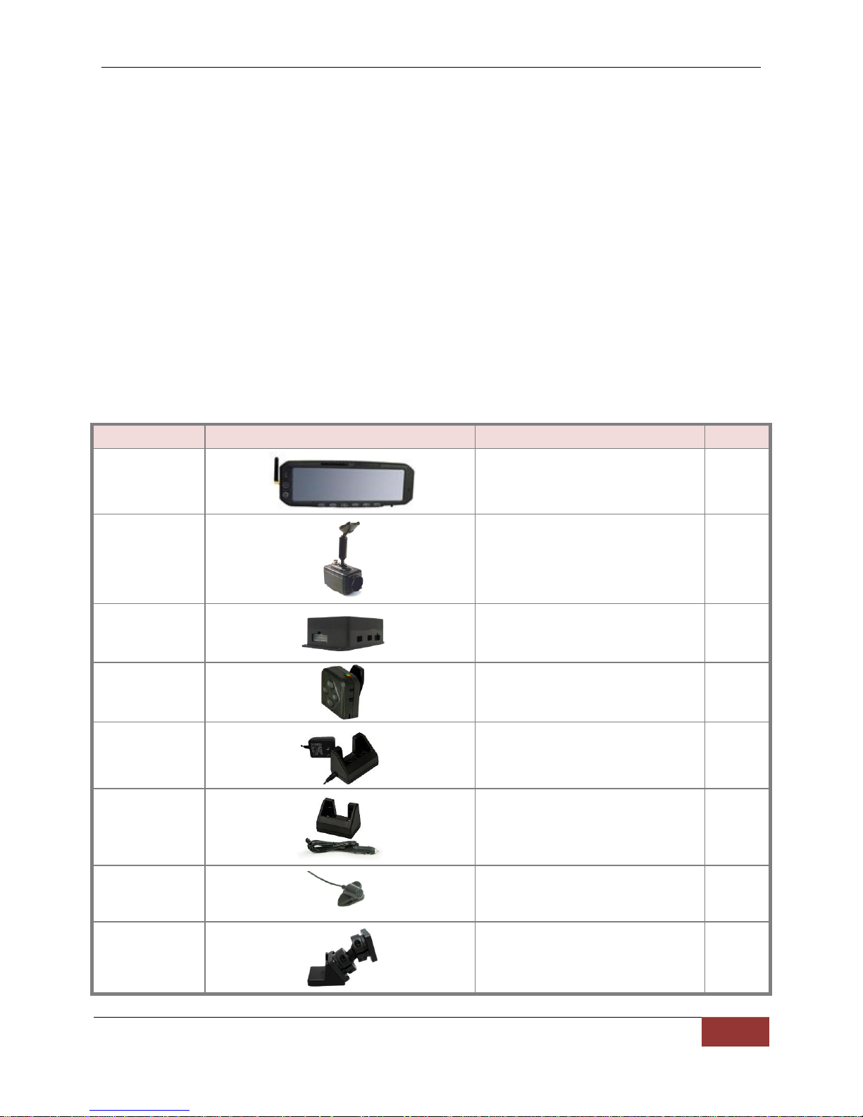
006-08188-00
DVM-750 with “rubber duck”
antenna and CF Card Installed V3
1
566-00125-00
Front Camera 10X Zoom
1
006-0076-01
Interface (I/O) Box
1
004-0502
VoiceVault™
Remote Mic (RMT)
(Includes 050-0130 Belt Clip)
1
004-0501 cradle
630-0511
Power Supply
Desktop Charging Cradle with AC
Power Adapter
1
004-0501 cradle
008-0104
Car Adapter
In Car Charging Cradle
with DC Auto Adapter
1
004-0902-00
Clip-on Style
Lapel Mic
1
002-05024-00
Big Ball Mirror Mount
1
BEFORE YOU BEGIN INSTALLATION
Tools Needed
#2 Philllips head screwdriver
#20 Torx screwdriver or bit
1/8” (4mm) flat blade screwdriver
Basic socket set
Multimeter
Power Drill
Velcro or double sided tape
Tie Wraps
PARTS AND ACCESSORIES
DVM-750 Standard Parts List
DVM-750 Installation Guide 860-0008-00 Rev C
Digital Ally, Inc |DVM-750 Installation Guide
3
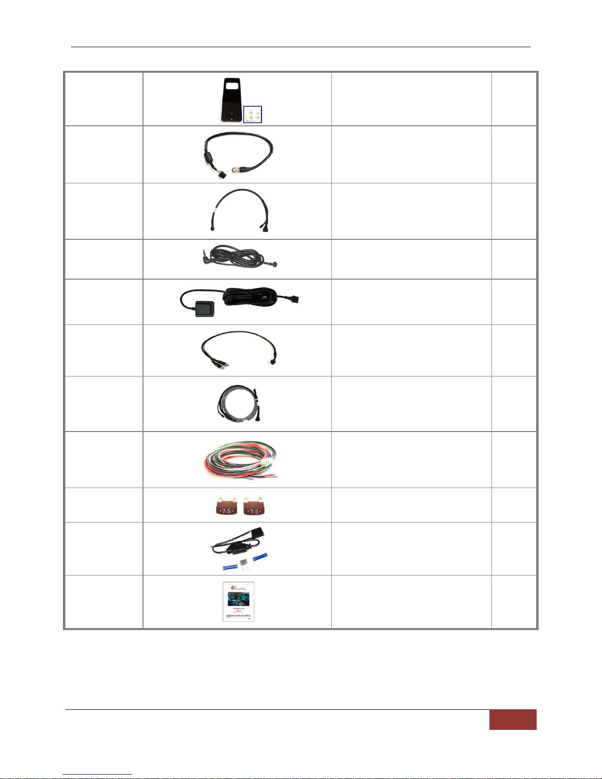
006-08255-00
Assembly, CAM visor mounting plate
standard
1
008-01324-00
Main Camera Cable
1
008-01281-00
Interface to Mirror Y Cable
1
006-0810-00
Covert Rear Seat Microphone
1
310-00100-10
GPS Receiver Module
1
008-01284-00
24” AV Dongle Cable
1
008-0051
(Gray portion only)
I/O Box to DVM
Wiring Harness
1
008-01287-00
Vehicle to I/O Box
Wiring Harness
1
280-0014
(Qty-2) 7.5 Amp Fuses
1
280-0011
280-0014
280-0012
In-Line Fuse Holder
7.5 Amp fuse
Butt splices
1
1
2
860-0008-00
DVM-750 Installation Guide
1

DVM-750 Installation Guide 860-0008-00 Rev C
Digital Ally, Inc |DVM-750 Installation Guide
4
Part Number
Image
Description
001-00555-00
WTM-555 wireless transfer module kit
006-0809-00
Auxiliary Rear Seat Camera
008-01272-00
15.5” Aux Camera Cable
002-05030-00
Drop Mount Adapter Kit
002-05123-00
Windshield Mount Adapter Kit,
Dodge Charger
008-01395-04
Cable, Main camera extension 4.5’
(circular connector)
008-01395-12
Cable, Main camera extension 12’
(circular connector)
006-08196-00
Front Camera (35x Zoom)
008-01273-00
008-01274-00
008-01275-00
008-01276-00
008-01277-00
008-01278-00
008-01279-00
008-01280-00
35x front camera cable
(available lengths from 10” to 48”)
002-05033-00
7” External Monitor Kit
002-05021-00
Handheld controller
DVM-750 Optional Parts List
DVM-750 Installation Guide 860-0008-00 Rev C
Digital Ally, Inc |DVM-750 Installation Guide
5
006-0047 CF card reader
006-08211-00
Assembly, CAM visor mounting plate,
Chevy Tahoe
006-0030
Assembly, CAM visor mounting plate,
Large
010-00070-00
Vu)Command™ Laptop interface kit
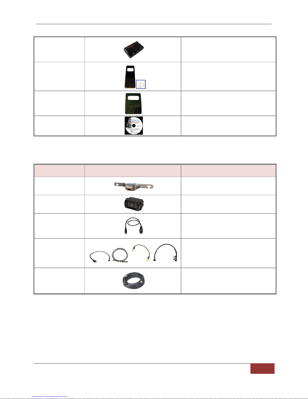
Part Number
Image
Description
566-00038-00
License Plate Mounted Backup Camera
566-00040-00
Surface Mounted Backup Camera with
mounting hardware
008-01449-00
CABLE OPTION 1
15ft Adapter Cable, Reverse Camera to DVM,
4 pin to 8 pin. Use when connecting backup
camera to the CAM2 input of the DVM
008-01281-01
008-01284-00
008-01272-00
008-01450-00
CABLE OPTION 2
Main power cable to DVM w/ camera power
pigtail, AV dongle cable, AV Cable, Aux Input
Cable. Use when connecting backup camera
to the A/V dongle input of the DVM
008-01382-00
008-01382-01
008-01382-02
008-01382-03
25ft Backup Camera Extension Cable
40ft Backup Camera Extension Cable
60ft Backup Camera Extension Cable
15ft Backup Camera Extension Cable
DVM-750 Optional Backup Camera Parts List
 Loading...