

Digital-Ally DVM-500Plus Installation Manual
DVM-500Plus Installation Guide 002-0501-02 REV C Page 1
Installation Guide
DVM-500Plus
Digital In-Car Video System
Copyright © 2009-2013, Digital Ally, Inc. All Rights Reserved, Printed in U.S.A. This publication may not be reproduced,
stored in a retrieval system, or transmitted in whole or part in any form or by any means electronic, mechanical,
recording, photocopying, or in any other manner without the prior written approval of Digital Ally, Inc.

DVM-500Plus Installation Guide 002-0501-02 REV C Page 2
Table of Contents
STANDARD LIMITED WARRANTY MODEL DVM-500PLUS ................................................................................. 3
BEFORE YOU BEGIN INSTALLATION ....................................................................................................................... 4
DVM-500PLUS PARTS LIST (001-0550-30) ................................................................................................................... 4
CAUTIONS & NOTES ....................................................................................................................................................... 6
DVM-500PLUS Interface Box Backup Battery ................................................................................................................ 6
Before powering on your new DVM-500PLUS ............................................................................................................... 6
SYSTEM DIAGRAM ......................................................................................................................................................... 7
SYSTEM INSTALLATION ............................................................................................................................................... 8
Step 1: Factory Mirror Removal .................................................................................................................................... 8
2011-2012 Dodge Charger Rearview Mirror Removal ................................................................................................ 8
Step 2: Remove Factory Body Trim .............................................................................................................................. 8
STEP 3: Attach the Mirror Mount................................................................................................................................... 10
Standard Mount ........................................................................................................................................................... 10
Mounting the mirror .................................................................................................................................................... 11
Optional Big Ball Mount ............................................................................................................................................. 11
STEP 4: Mirror Connections ........................................................................................................................................... 13
STEP 5: Camera Installation ........................................................................................................................................... 14
STEP 6: GPS and Rear Microphone Connections .......................................................................................................... 15
STEP 7: Power, Ignition, Ground, and Trigger Connections .......................................................................................... 15
Wiring Connections Chart .......................................................................................................................................... 16
STEP 8: Mount the Interface Box ................................................................................................................................... 17
STEP 9: Wireless Microphone Charging Cradle ............................................................................................................ 17
IMPORTANT NOTES WHEN INSTALLING AND USING YOUR DVM-500PLUS .............................................. 17
POST INSTALLATION CHECKLIST .......................................................................................................................... 18
HOW TO RESET THE DVM-500PLUS SYSTEM ....................................................................................................... 18
TROUBLESHOOTING ................................................................................................................................................... 19
PRODUCT REPAIR ......................................................................................................................................................... 20

DVM-500Plus Installation Guide 002-0501-02 REV C Page 3
STANDARD LIMITED WARRANTY
MODEL DVM-500PLUS
REAR VIEW MIRROR IN-VEHICLE DIGITAL VIDEO SYSTEM
We warranty that our In-Car Digital Video System, Model DVM-500Plus, will be free from defects in
workmanship and material for a period of 24 months from the date of purchase by the original purchaser. If
any defect is discovered through normal and proper use of the unit during this period, the defect will be
repaired or the unit will be replaced at our factory or at one of our authorized service centers at no cost to the
purchaser. The purchaser must return the defective unit to the factory or one of our authorized service
centers, freight prepaid. We will pay for shipping charges for the return of the unit.
This warranty applies only to defects in a unit’s internal electronic components and circuitry, and is void as to
units that have been opened without prior authorization, have experienced unauthorized repairs, or have had
unauthorized modifications. This warranty does not cover the following:
Normal wear and tear on the unit such as batteries, frayed cables or wires, broken connectors, or
scratched or broken cases.
Damage caused by operator abuse or neglect.
Damage caused by incorrect use of the unit, carelessness, unauthorized alterations to the unit,
improper storage of the unit or unauthorized service, installation or repairs made to the unit.
Damage caused by fire, flood, lightning, vandalism, collision, Acts of God, or other events
beyond the reasonable control of Digital Ally, Inc. or the purchaser.
Damage to external parts of the unit such as buttons, microphones, wires, and cables, etc.
Damage from use of the unit in hostile operating environments.
We reserve the right to charge for repairs to a unit during the warranty period made necessary because of
any of the foregoing causes at our standard rates for repair of units not under warranty.
The purchaser assumes all risk of use from its purchase and use of the unit. Harmful personal contact with a
unit might occur in the event of violent maneuvers, collisions, or similar circumstances, even if the unit was
properly installed and used. We are not responsible for, and we specifically disclaim any liability for injury
caused by a unit in such circumstances.
THIS WARRANTY IS GIVEN IN LIEU OF ALL OTHER WARRANTIES. THERE ARE NO WARRANTIES
THAT EXTEND BEYOND THIS STATEMENT. ALL IMPLIED WARRANTIES ARE DISCLAIMED,
INCLUDING, WITHOUT LIMITATION, WARRANTIES OF MERCHANTABILITY, NON-INFRINGEMENT,
FITNESS FOR A PARTICULAR PURPOSE, AND WARRANTIES IMPLIED FROM A COURSE OF
DEALING, COURSE OF PERFORMANCE OR USAGE OF TRADE. THE PURCHASER’S SOLE AND
EXCLUSIVE REMEDY FOR A WARRANTY CLAIM WILL BE THE REPAIR OR REPLACEMENT OF A
UNIT.
DVM-500Plus Installation Guide 002-0501-02 REV C Page 4
BEFORE YOU BEGIN INSTALLATION
Tools Needed
#2 Phillips head screwdriver
#20 Torx screwdriver or bit
1/8” (4mm) flat blade screwdriver
Basic socket set
Multimeter
Power Drill
Velcro or double sided tape
Tie Wraps
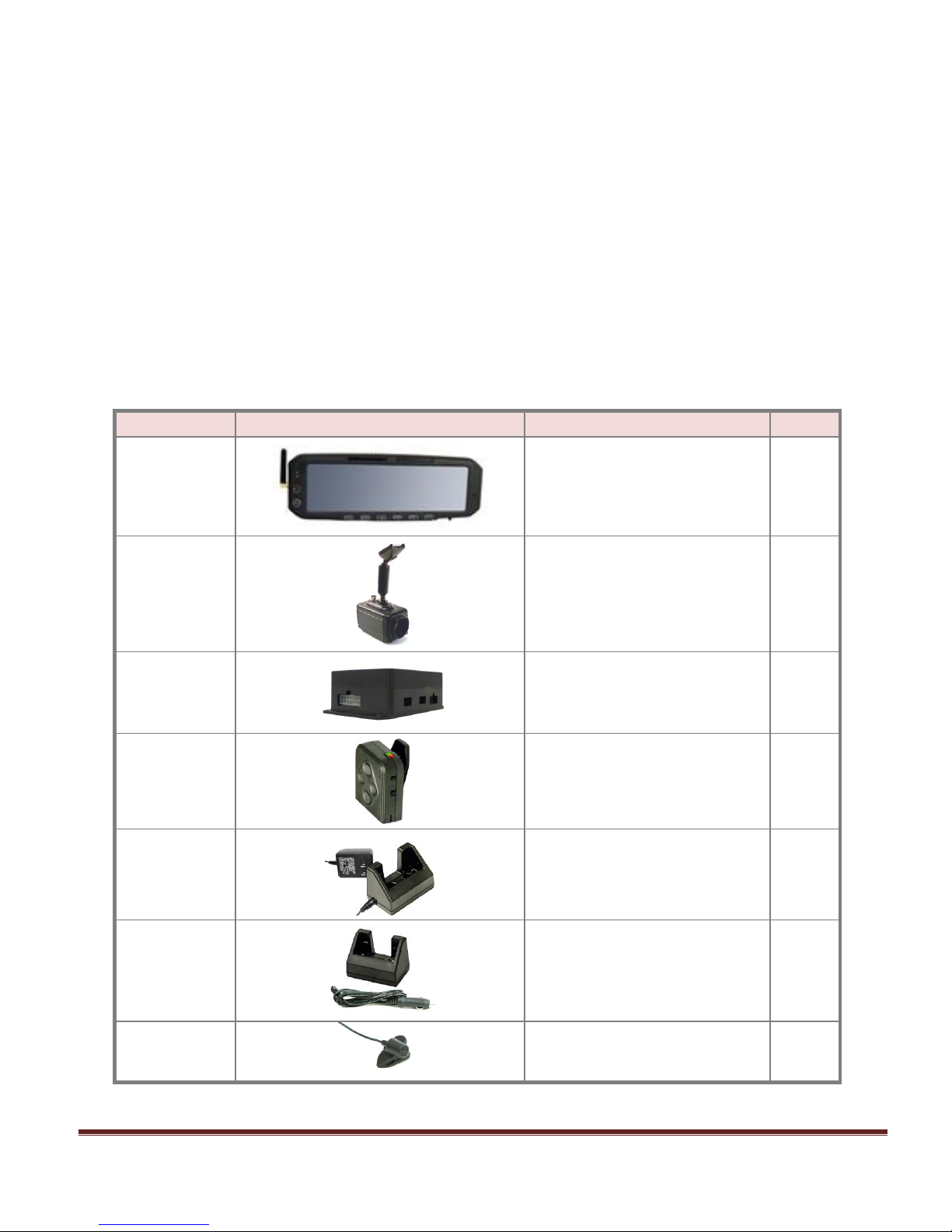
DVM-500PLUS PARTS LIST (001-0550-30)
Part Number
Image
Description
Quantity
006-08186-00
DVM-500PLUS with “rubber duck”
antenna and CF Card Installed
1
566-00125-00
Main Camera 10X Zoom
1
006-0076-01
Interface (I/O) Box
1
004-09060-00
VoiceVault™
Wireless Mic (RMT)
(Includes 050-0130 Belt Clip)
1
004-0506-00
Desktop Charging Cradle
with AC Power Adapter
1
004-0507-00
In Car Charging Cradle
with DC Auto Adapter
1
004-0902-00
Clip-on Style
Lapel Mic
1

DVM-500Plus Installation Guide 002-0501-02 REV C Page 5
006-08255-00
Visor Mount for Main Camera
1
008-08132-01
Main Camera Cable
1
008-01281-00
Interface to Mirror Y Cable
1
006-0810-00
Covert Rear Seat Microphone
1
310-00100-10
GPS Receiver Module
1
008-0051
(Gray portion only)
I/O Box to DVM
Wiring Harness
1
008-01287-00
Vehicle to I/O Box
Wiring Harness
1
280-0014
(Qty-2) 7.5 Amp Fuses
1
280-0011
280-0014
280-0012
In-Line Fuse Holder
7.5 Amp fuse
Butt splices
1
1
2
006-0808-00
Auxiliary Rear Seat Camera (optional)
Call
Sales
002-05030-00
Kit, Drop Mount (optional)
Call
Sales
002-05023-00
Big Ball Mirror Mount with Adapter
Plate (optional)
Call
Sales
002-05112-00
Windshield Mount Adapter Kit
(Optional, Dodge
Charger only)
Call
Sales

DVM-500Plus Installation Guide 002-0501-02 REV C Page 6
CAUTIONS & NOTES
Please read and follow the instructions and precautions in this installation guide when installing the DVM500PLUS system.
For assistance, a qualified installation technician or mechanic should be consulted.
Do not route wiring and cabling over sharp metal edges where they may become damaged or cut.
To prevent electrical shorts or breakage in the wiring and cabling, do not allow wiring and cabling to
be pinched behind trim pieces, panels, etc.
Do not run wires or cables in areas where they become damaged by heat from the engine or the
exhaust system.
Do not install any in-car video system components or wiring in the deployment path of the air bag(s).
When installing the cables or making wire connections, it is recommended you allow for service loops
and leave a little ‘slack’ in the cable connections to allow for service loops and to allow for movement
of the mirror so the connections do not get pulled or accidentally disconnected.
Avoid running cables parallel to other wiring and/or antenna coax of other systems that may be
installed in the vehicle and do not leave excessive cable above the headliner. Doing so may cause
Radio Frequency (RF) interference in the video or audio recordings of the DVM system.
If installing the optional Wireless Transfer Module (WTM), consult the WTM-555 installation
instructions.
DVM-500PLUS Interface Box Backup Battery
This system is equipped with a Backup Battery that is located in the Interface Box (pictured on page 16 of this
manual). In case of vehicle power failure, the Backup Battery will maintain power to your DVM-500Plus
system for 30-90 minutes. If the Backup Battery does not have a high enough charge at the time of
installation, the DVM-500Plus system may not turn on correctly the first time. It may be necessary to charge
the Backup Battery.
**To charge the Backup Battery, install your DVM-500Plus system, but do not turn it on. Start the
vehicle and allow the vehicle to idle for 5-10 minutes.
Before powering on your new DVM-500PLUS
Your DVM-500Plus system comes equipped with a Compact Flash card that the system records all of your
video files to. In order to ensure that you receive the latest features and benefits your system has to offer,
please follow the following steps before turning on your system for the first time:
Logon to www.digitalallyinc.com/tech-support.php and register for an account to be an
Authorized User. By registering, you will be able to download all of the latest software and firmware
updates and you will also be notified of all future updates.
Download the latest firmware, copy the file to your Compact Flash Card that was included with your
system, and follow the Firmware Update instructions in your DVM-500PLUS User’s Guide.
For further assistance, please contact our Technical Support staff at: Phone: Toll-Free 1-800-440-
4947 or 1-913-814-7774 Email: support@digitalallyinc.com.
DVM-500Plus Installation Guide 002-0501-02 REV C Page 7
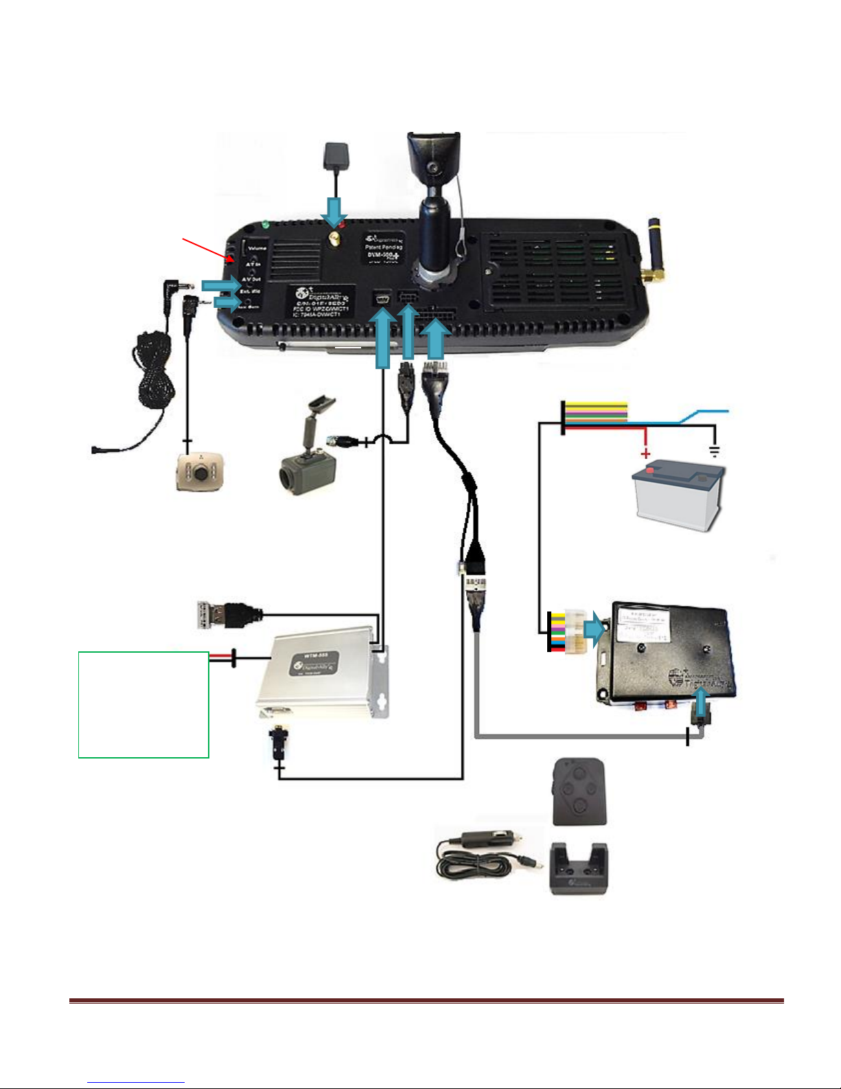
SYSTEM DIAGRAM
GPS Antenna
Optional Back Seat Camera Front Camera
WIFI USB Dongle
Interface Box
External Microphone
Wireless Transfer
Module (optional)
USB1
USB2
Serial
WTM POWER HARNESS
RED = Constant 12V+
WHITE = Switched 12V+
BLACK = Ground
(See WTM-555
installation guide)
Constant 12V+ Ground
Switched
Ignition 12V+
Input Triggers
(see page 17)
Vehicle to IF
Box Harness
DVM to I/O Box harness
Shown With Optional
Wireless Transfer Module
(WTM)
Voice Vault Wireless Microphone and Charger
Assembly with Cigarette Lighter Adapter
DVM Y Cable
WTM to DVM serial cable
Optional A/V
Connections
 Loading...