

Page 1
Installation Guide
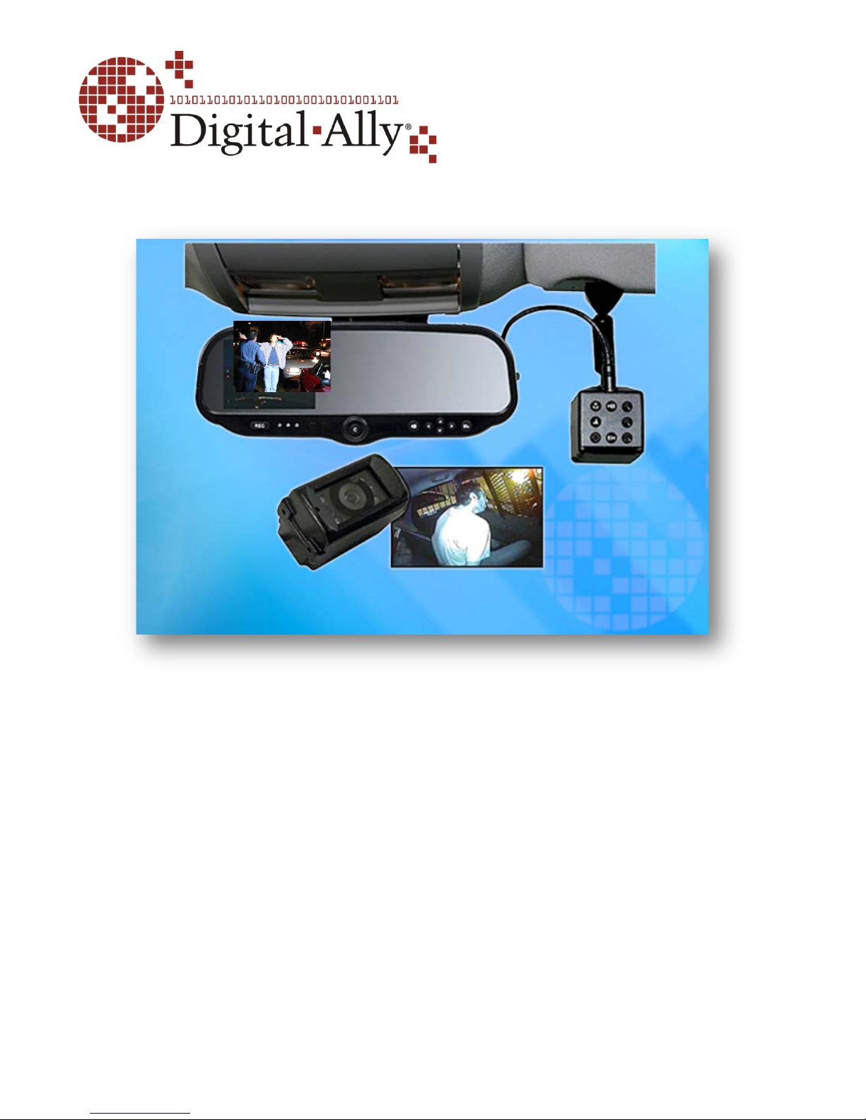
DVM-100 and DVM-400
860-00187-00.docx
Digital In-Vehicle Event Recorder Video System
Copyright © 2013, Digital Ally, Inc. All Rights Reserved. This publication may not be reproduced, stored in a retrieval system, or
transmitted in whole or part in any form or by any means electronic, mechanical, recording, photocopying, or in any other
manner without the prior written approval of Digital Ally, Inc.
Page 2

DVM-100 & DVM-400 Installation Guide 860-00187-00 REV A
Tabl e of Contents
SECTION - 1: BEFORE YOU BEGIN .............................................................................................. 1-1
OOLS NEEDED .................................................................................................................................... 1-1
T
C
AUTIONS AND NOTES ........................................................................................................................ 1-1
SECTION - 2: P ARTS, CABLES AND ACCESSORIES.................................................................. 2-1
DVM-100 ............................................................................................................................................ 2-1
Parts and Accessories List ............................................................................................................. 2-1
Cables and Optional Accessories .................................................................................................. 2-2
DVM-100 Wiring Diagram ........................................................................................................... 2-3
DVM-400 ............................................................................................................................................ 2-4
Parts and Accessories List ............................................................................................................. 2-4
Cables and Optional Accessories .................................................................................................. 2-5
DVM-400 Wiring Diagram ........................................................................................................... 2-6
SECTION - 3: INSTALLATION INSTRUCTIONS ......................................................................... 3-1
S
TEP 1: FACTORY MIRROR REMOVAL ........................................................................................... 3-1
S
TEP 2: DVM INSTALLATION ......................................................................................................... 3-2
S
TEP 3: MIRROR CONNECTIONS .................................................................................................... 3-3
S
TEP 4: CAMERA INSTALLATION (DVM-400 ONLY)...................................................................... 3-5
S
TEP 5: POWER, IGNITION, AND GROUND CONNECTION ............................................................... 3-6
S
TEP 6: DWM-800 INSTALLATION AND TRIGGER CONNECTION ................................................... 3-6
S
TEP 7: WI-FI ANTENNA (OPTIONAL) ............................................................................................ 3-7
SECTION - 4: TESTING THE INSTALLATION ............................................................................ 4-1
SECTION - 5: SUPPORT .................................................................................................................... 5-1
S
OFTWARE UPDATES ............................................................................................................................ 5-1
P
ERFORMING A RESET ......................................................................................................................... 5-1
T
ROUBLESHOOTING ............................................................................................................................. 5-1
SECTION - 6: CONTACT INFORMATION .................................................................................... 6-1
Copyright © 2010-2012 Digital Ally, Inc.
i
Page 3

DVM-100 & DVM-400 Installation Guide 860-00187-00 REV A
Section - 1: Before you Begin
This document covers the installation of the DVM-100 and DVM-400 systems only.
Tools Needed
• #2 Phillips head screwdriver
• #20 Torx screwdriver or bit
• 1/8" (4 mm ) flat-blade screwdriver
• Digital Volt Meter
Cautions and Notes
Please read and follow the instructions and precautions in this installation guide when installing
DVM-100 and DVM-400 products.
• For assistance, a qualified installation technician or mechanic should be consulted.
• Do not use excessive force when removing the mirror from the windshield. The mirror
mounting plate may become separated from the windshield and/or the windshield may
break if excessive force is used. If you are unfamiliar with rearview mirr or removal seek
professional assistance.
• Do not route wiring and cabling over sharp metal edges where they may become damaged
or cut.
• To prevent electrical shorts or breakage in the wiring and cabling, do not allow wiring and
cabling to be pinched behind trim pieces, panels, or other physical objects.
• Do not run wires or cables in areas where they may become damaged by heat from the
engine or the exhaust system.
• Do not install any DVM components or wiring in the deployment path of the air bag(s).
• W hen installing the cables or making wire connections, it is recommended you leave a little
‘slack’ in the cable connections to allow for service loops and for movement of the mirror so
the connections do not get pulled or accidentally disconnected.
• Where possible, avoid running cables parallel to other wiring and/or antenna coax that may
be installed in the vehicle.
• Where possible, do not leave excessive cable above the headliner.
• We recommend at least 2 feet of distance between our cabling and that of other systems
which may carry a signal for transmit and/or receive.
Additional precautions within this document are denoted with and
notes are designated with
Copyright © 2013 Digital Ally, Inc.
1-1
Page 4
DVM-100 & DVM-400 Installation Guide 860-00187-00 REV A
Cables and optional accessories are not incl ud ed in th e base DV M -100
package and are ordered separately. Refer to page
items.
Part Number
Image
Description
Quantity
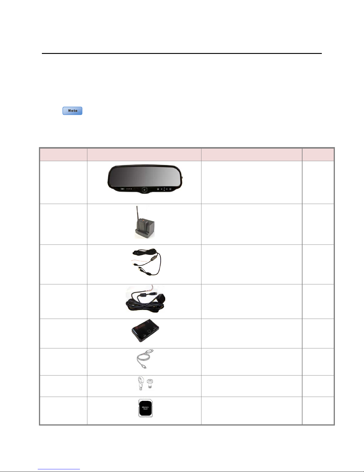
Base mirror with mount & 8GB
Section - 2: Parts, Cables and Accessories
DVM-100
Parts and Accessories List
The diagram and table below outline the parts that are included with the DVM-100 Package.
006-08163-00
002-05095-00
008-01372-01
2-2 for a list of these
DVM-100
SD card
DWM-800 Wireless Microphone System 1
Cable Assembly, BTR800 to DVM-100 1
1
008-01373-01
002-00028-00
008-01271-00
259-00176-00
363-00046-00
Copyright © 2013 Digital Ally, Inc.
2-1
Power Cable Assembly 1
Card Reader 1
USB Cable 1
Security Key Kit 1
8 GB Memory Card 1
Page 5
DVM-100 & DVM-400 Installation Guide 860-00187-00 REV A
Part Number
Image
Description
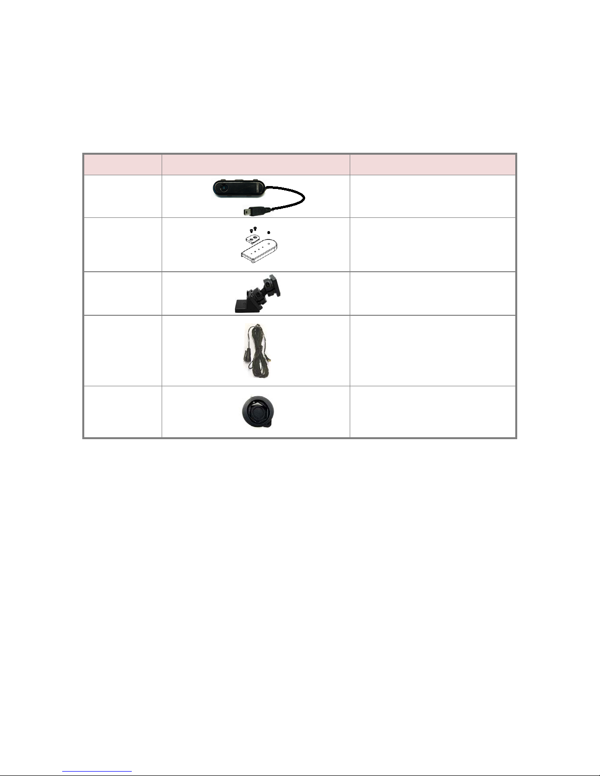
Cables and Optional Accessories
The table below outlines cables and optional accessories for the DVM-100 package.
001-00010-00
002-05030-00
002-05102-00
004-09058-00
002-05112-00
Wi-Fi Ass embly
Drop Mount
Big Ball Mirror Mount
Covert Rear Seat Microphone
Windshield Mount Adapter Kit ( 2011-
2012 Dodge Charger only)
Copyright © 2013 Digital Ally, Inc.
2-2
Page 6
DVM-100 & DVM-400 Installation Guide 860-00187-00 REV A
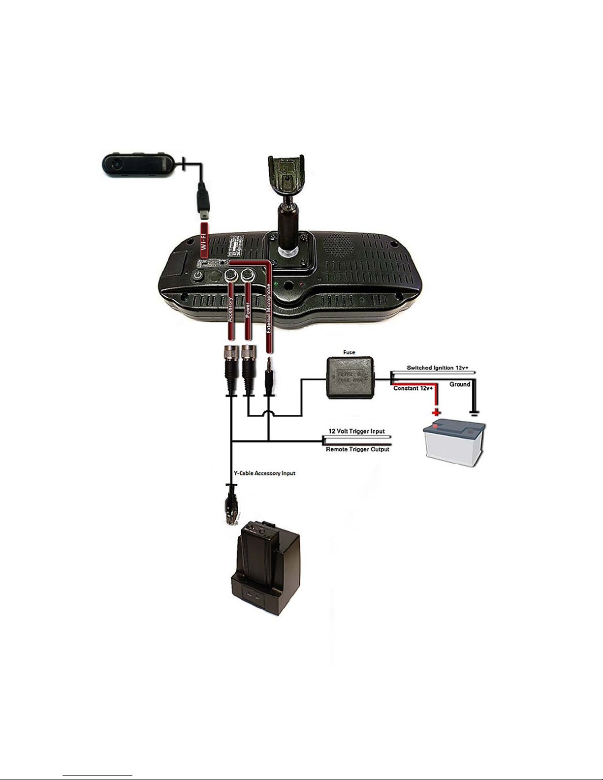
Optional Wi-fi Antenna
Wireless microphone and charger
DVM-100 Wiring Diagram
Copyright © 2013 Digital Ally, Inc.
2-3
Page 7

DVM-100 & DVM-400 Installation Guide 860-00187-00 REV A
Cables and optional accessories are not included in the base DVM-400 package;
these items are ordered separately.
Part Number
Image
Description
Quantity
400 Base mirror with mount & 8GB
DVM-400
Parts and Accessories List
The diagram and table below outline the parts that are included with the DVM-400 Package.
006-08177-00
CAM-10XC
566-00039-00
002-05095-00
Refer to page 2-5 for a list of these items.
DVM-
SD card
Main Camera 10X Zoom 1
External or Backseat Camera with
mounting hardware
DWM-800 Wireless Microphone System 1
1
1
006-0030
008-01372-01
008-01393-00
008-01373-01
Cable Assembly, BTR800 to DVM400 1
Camera Cable, DVM400 to CAM1 and
002-00028-00
Copyright © 2013 Digital Ally, Inc.
2-4
Visor Mount for Main Camera 1
CAM2
Power Cable Assembly 1
Card Reader and USB cable 1
1
Page 8

DVM-100 & DVM-400 Installation Guide 860-00187-00 REV A
Part Number
Image
Description
Cables and Optional Accessories
The table below outlines cables and optional accessories for the DVM-400 package
001-00010-00
002-05030-00
002-05102-00
004-09058-00
002-05112-00
Wi-Fi Ass embly
Drop Mount
Big Ball Mirror Mount
Covert Rear Seat Microphone
Windshield Mount Adapter Kit ( 2011-
2012 Dodge Charger only)
Copyright © 2013 Digital Ally, Inc.
2-5
Page 9

DVM-100 & DVM-400 Installation Guide 860-00187-00 REV A
Optional Wi-fi Antenna
Fuse
Wireless microphone and charger
Front Camera
Rear Camera
DVM-400 Wiring Diagram
Copyright © 2013 Digital Ally, Inc.
2-6
Page 10

DVM-100 & DVM-400 Installation Guide 860-00187-00 REV A
Be very careful and do not use excessive force when removing the mirror
from the windshield. The mirror mounting plate may bec
the windshield and/or the windshield may break if excessive force is used.
Section - 3: Installation Instructions
Factory Mirror Removal Step 1:
The current factory rearview mirror must be removed from the windshield mounting plate. There
are several versions of mirror mounting systems. Below are the most common m ethods of
rearview mirror re mo val. If you are unfamiliar with rearview mirror removal, seek professional
assistance.
ome separated from
Use one of the following methods below that matches the mirror mounting configuration of your
vehicle:
Screw Mount Rearview Mirror Removal
1. Using a Philips screwdriver or #20 Torx bit, loosen the screw in the base of the mirror.
2. After loosening the screw, gently lift upward to slide mirror off of mirror mount.
3.
Wedge (screw-less) Mount Rearview Mirror Removal
1. Using a small 1/8" (4 mm) flat-blade screwdriver, insert the flat end into the opening at
the bottom of the mirror mount next to the windshield.
2. Slide the screwdriver into the center of the mirror mount until resistance is felt.
3. Gently apply a small amount of additional upward force to lift away the lock ing spring
inside the mount.
4. While still applying upward pressure with the screwdriver, grasp the mirror bracket and
wiggle side to side. Lift the mirror up toward the headliner and off the windshield mount
button.
Cam Lock Rearview Mirror Removal
1. With your right hand, grip the mirror and keep it stabilized.
2. With your left hand, grip the base of the factory mount where it meets the glass.
3. Apply a small amount of inward pressure toward the glass and rotate the base
clockwise.
4. The spr ing loaded factory mount should release from the windshield puck. See picture
below.
Copyright © 2013 Digital Ally, Inc.
3-1
Page 11

DVM-100 & DVM-400 Installation Guide 860-00187-00 REV A
DVM Installation Step 2:
1. remove front passenger side threshold
2. pull the door seal away and remove side trim piece
3. remove the passenger side front interior A-pillar cover
Copyright © 2013 Digital Ally, Inc.
3-2
Page 12

DVM-100 & DVM-400 Installation Guide 860-00187-00 REV A
4. remove the passenger visor clip with #20 Torx screwdriver
5. remove the passenger side kick panel & pull back the carpet to expose the vehicle
chassis
Mirror Connections Step 3:
Attach the ACC and PWR IN cables to the back of the mirror. For DVM-400, attach the
CAM IN cable. Attach the ground strap to the vehicle roofline above the headliner.
Copyright © 2013 Digital Ally, Inc.
3-3
Page 13

DVM-100 & DVM-400 Installation Guide 860-00187-00 REV A
Optional Big Ball Mount
Secure your DVM to the vehicle windshield. For 2011 or 2012 Dodge, attach and orientate the
adapter to factory windshield as shown. Use Loctite™ to secure the adapter to the factory
windshield mounts. Attach drop down bracket as shown.
In some vehicles, the factory position of the manufacturer’s windshield mounting plate may not allow for
proper rearview DVM adjustment. The mounting plate included with the DVM package can be glued to
the windshield in a location that will allow proper adjustment. We recommend Loctite 03346 for
installation of the mounting plate. DO NOT glue mounting plates to the black coated portion of the glass.
For added RFI protection, attach the DVM shielding strap to the mirror. The DVM shielding strap
should be securely attached to the vehicle chassis (metal structure) above the windshield.
The shielding strap must be connected to a metal surface of the vehicle chassis to prevent
interference. Failure to properly connect the shielding strap may cause operation issues.
•
Route cabling along the roofline and down the A-pillar
Leave enough slack in the 3 cables as a service loop for the rearview mirror adjustment.
Then you can begin routing the cables under the front edge of the headliner towards the
passenger side of the vehicle. Continue routing the cables down the windshield pillar
below the dash. Secure the cables toget her with tie wraps. To conceal the cable it may
be necessary to loosen the sun visor mounting bracket and/or other trim pieces to allow
the cable to be tucked in behind the headliner.
Copyright © 2013 Digital Ally, Inc.
3-4
Page 14

DVM-100 & DVM-400 Installation Guide 860-00187-00 REV A
• Attach the visor mount through the visor clip and attach front camera to the
mounting plate (DVM-400 only)
Camera Installation (DVM-400 Only) Step 4:
Front Camera
• Route the cable toward the 10x
camera and connect to the CAM10XC. Attach the camera to the
visor mounting plate. (The DVM-100
front camera is embedded in the
rear of the unit).
Rear Camera
• Determine a mounting location for the rear
camera. The example below has the camera
mounted in the center of the cage. This gives a
wide angle view of the entire back seat. Route
the remaining portion of the camera cable to
the external surface mount camera and
connect. Secure extra cable in the headliner
away from any other existing cabling and/or
airbag.
Copyright © 2013 Digital Ally, Inc. 3-5
Page 15

DVM-100 & DVM-400 Installation Guide 860-00187-00 REV A
Power, Ignition, and Ground
Step 5:
Connection
Remove 6 to 7 inches of the outer jacket at the bare end of the power cable. The Red wire of
the DVM power cable should be connected to the vehicle constant +12Vdc. Connect the
wire to the ignition switch where +12vdc is only present when the vehicle ignition key is in the
ON position. The Black wire of this power cable connects directly to the vehicle’s chassis.
Separate the braided shield from the individual conductors, attach an electrical terminal to the
end of the braided shield, and attach the terminal to the chassis of the vehicle. Secure all
cables and in-line fuse housing using Velcro or standard tie wraps as required. If the accessory
connector cannot be found, use an alternate source of battery
power.
• It is required that this power wire be tied directly to vehicle
power with no obstructions to the vehicle battery such as a
cutoff switch or charge guard system.
• The power cable contains an in-line filter and 3A fuse.
I
t is recommended that these connections are made directly to
the police package accessory harness or engine compartment battery
wiring harness for best results. These wires should be used ONLY for the DVM system and not be tapped
into for installation of any other equipment in the vehicle. Doing so, could result in possible radio
frequency interference from the other equ ip ment .
DWM-800 Installation Step 6:
and Trigger Connection
1. Attach the mounting bracket to the back of the BTR (base
transceiver cradle); the assembly can then be mounted at your
preferred location, such as the side of the center console.
2. Attached the antenna. If you are using the optional In-Car
Microphone, connect it to the BTR In-Car Microphone jack and route the microphone to
your preferred location in your system.
Important: if not using an external microphone, do NOT attach the microphone input on
the back of the DVM mirror. The DVM will then use the built-in microphone located next
to the record button on the front of the mirror.
3. Connect the BTR cable assembly to the RJ-45 input on the BTR.
Copyright © 2013 Digital Ally, Inc. 3-6
Page 16

DVM-100 & DVM-400 Installation Guide 860-00187-00 REV A
Wi-Fi Antenna (optional)
4. On the BTR800 cable assembly, connect the WHITE wire to the emergency lights or
other +12VDC positive trigger. This wire will trigger the system to record when in the
active state. Optionally, the BROWN wire is designed to be a 12V output alarm when
the Emergency button is pressed on the RMT. This could be connected to a police radio
or other remote accessory.
Pressing the Emergency button will not trigger a record event.
Below is a general outline showing how the BROWN wire can be wired using an
interposing relay.
The device, relay, and fuse are optional customer provided items. Be sure to select a
relay which can handle the power requirements of your device.
Example wiring diagram :
To activate low power devices when the Emergency Button is active, the
example diagram below shows how to connect it to the BTR800 cable assembly.
When the Output alarm is active the relay will be energized and the device
will be powered on. If the Output Alarm is not active, the relay will not be
energized and the device will not be powered.
Plug the Wi-Fi antenna into the USB port on the back of
the DVM. Using the included double-sided tape, attach
the antenna to an unobstructed location on the
windshield below the roofline.
Refer to the DV M -100 or DVM-400 operation guide for
configuration of the wireless transfer feature.
Copyright © 2013 Digital Ally, Inc. 3-7
Step 7:
Page 17

DVM-100 & DVM-400 Installation Guide 860-00187-00 REV A
Section - 4: Testing the Installation
1. Turn the vehicle ignition switch to the ON position, the vehicle does not have to be
running.
2. Press and release the DVM power button and the DVM boot-up process will begin; all 3status indicators will flash in sequence until boot up is complete.
3. Once the boot-up process is complete the Blue status indicator will be lit, indicating the
DVM is powered on and in standby mode.
4. Press the RECORD Start button.
5. The Red status indicator will turn on to indicate the event is being recorded.
6. After 10 seconds, press the RECORD Stop button to stop the event record.
7. Remove the wireless microphone from the charging cradle and press the record button.
8. The Red status indicator will turn on again to indicate the event is being recorded.
9. After 10 seconds, press the RECORD Stop button to stop the event record.
10. The Red status indicator will extinguish, indicating the DVM has returned to standby
mode.
11. Press the Play/Pause button and the event will playback on the DVM-400 display.
Copyright © 2013 Digital Ally, Inc.
4-1
Page 18

DVM-100 & DVM-400 Installation Guide 860-00187-00 REV A
System will not power up.
• Verify the power cable connector is connected to the back of the DVM.
Red/Blue/Green status
• Memory is full, upload event files from the DVM or replace the
DVM powers up but doesn’t
• Check the LED status indicators for possible error cond itions
DVM powers up and goes
An event record has been triggered from either an accessory or the record
DVM is unresponsive
• Verify the cables and cable connections.
Section - 5: Support
Software Updates
Log on to www.digitalallyinc.com/tech-support.php and Register for an Account to be an
Authorized User. By registering you will be able to download all the latest software updates
and be notified of future updates.
Performing a Reset
Using a small device such as a paper clip
or eye-glass screwdriver, press the
recessed reset button that is located as
shown to the right.
Troubleshooting
Symptom Resolution
• Check the power cable fuses located in the in-line fuse housing on the
power cable.
• Verify there are no breaks, pinches, or cuts in the wiring or cable harness.
• Check the wiring and voltage levels to the vehicle power and ignition switch
wiring.
indicators blink in unison
record
directly to an event record
(Red indicator flashes)
external memory storage device.
• Reset the system.
button is stuck
• Check the DVM record butt on t o make sure it is freely mov in g
• Disconnect the Accessory cable from the back of the DVM and reset the
DVM. If the problem doesn’t re-occur, refer to the accessory item
documentation for further troubleshooting.
• Verify vehic le power.
• Press the reset button.
Product Repair
The Digital Video Mirror should be returned to the manufact urer for service. The warranty may
be voided if the device is opened by any unauthorized individual. Please contact Digital Ally to
obtain an authorized Return Materials Authorization (RMA). It is helpful and will expedite the
process if you have your unit’s serial number available at the time of your call.
All In-Warranty and Out-of-Warranty service must be performed by Digital Ally,
Inc. There are no user serviceable parts inside of the DVM. Any user
serviceable items can be purchased directly through Digital Ally.
Copyright © 2013 Digital Ally, Inc. 5-1
Page 19

DVM-100 & DVM-400 Installation Guide 860-00187-00 REV A
Website:
www.digitalallyinc.com
Support E-Mail:
support@digitalallyinc.com
Sales E-Mail:
sales@digitalallyinc.com
Phone:
913-814-7774
Fax:
913-814-7775
Sales / Support Toll Free:
1-800-440-4947
Section - 6: Contact Information
9705 Loiret Blvd
Lenexa, KS 66219
* Specifications subject to change without notice.
Copyright © 2013 Digital Ally, Inc.
6-1
 Loading...