

Digital-Ally DVM-100, DVM-400 Installation Manual
Installation Guide
DVM-100 and DVM-400
860-00187-00.docx
Digital In-Vehicle Event Recorder Video System
Copyright © 2013, Digital Ally, Inc. All Rights Reserved. This publication may not be reproduced, stored in a retrieval system, or
transmitted in whole or part in any form or by any means electronic, mechanical, recording, photocopying, or in any other
manner without the prior written approval of Digital Ally, Inc.

DVM-100 & DVM-400 Installation Guide 860-00187-00 REV A
Tabl e of Contents
SECTION - 1: BEFORE YOU BEGIN .............................................................................................. 1-1
OOLS NEEDED .................................................................................................................................... 1-1
T
C
AUTIONS AND NOTES ........................................................................................................................ 1-1
SECTION - 2: P ARTS, CABLES AND ACCESSORIES.................................................................. 2-1
DVM-100 ............................................................................................................................................ 2-1
Parts and Accessories List ............................................................................................................. 2-1
Cables and Optional Accessories .................................................................................................. 2-2
DVM-100 Wiring Diagram ........................................................................................................... 2-3
DVM-400 ............................................................................................................................................ 2-4
Parts and Accessories List ............................................................................................................. 2-4
Cables and Optional Accessories .................................................................................................. 2-5
DVM-400 Wiring Diagram ........................................................................................................... 2-6
SECTION - 3: INSTALLATION INSTRUCTIONS ......................................................................... 3-1
S
TEP 1: FACTORY MIRROR REMOVAL ........................................................................................... 3-1
S
TEP 2: DVM INSTALLATION ......................................................................................................... 3-2
S
TEP 3: MIRROR CONNECTIONS .................................................................................................... 3-3
S
TEP 4: CAMERA INSTALLATION (DVM-400 ONLY)...................................................................... 3-5
S
TEP 5: POWER, IGNITION, AND GROUND CONNECTION ............................................................... 3-6
S
TEP 6: DWM-800 INSTALLATION AND TRIGGER CONNECTION ................................................... 3-6
S
TEP 7: WI-FI ANTENNA (OPTIONAL) ............................................................................................ 3-7
SECTION - 4: TESTING THE INSTALLATION ............................................................................ 4-1
SECTION - 5: SUPPORT .................................................................................................................... 5-1
S
OFTWARE UPDATES ............................................................................................................................ 5-1
P
ERFORMING A RESET ......................................................................................................................... 5-1
T
ROUBLESHOOTING ............................................................................................................................. 5-1
SECTION - 6: CONTACT INFORMATION .................................................................................... 6-1
Copyright © 2010-2012 Digital Ally, Inc.
i

DVM-100 & DVM-400 Installation Guide 860-00187-00 REV A
Section - 1: Before you Begin
This document covers the installation of the DVM-100 and DVM-400 systems only.
Tools Needed
• #2 Phillips head screwdriver
• #20 Torx screwdriver or bit
• 1/8" (4 mm ) flat-blade screwdriver
• Digital Volt Meter
Cautions and Notes
Please read and follow the instructions and precautions in this installation guide when installing
DVM-100 and DVM-400 products.
• For assistance, a qualified installation technician or mechanic should be consulted.
• Do not use excessive force when removing the mirror from the windshield. The mirror
mounting plate may become separated from the windshield and/or the windshield may
break if excessive force is used. If you are unfamiliar with rearview mirr or removal seek
professional assistance.
• Do not route wiring and cabling over sharp metal edges where they may become damaged
or cut.
• To prevent electrical shorts or breakage in the wiring and cabling, do not allow wiring and
cabling to be pinched behind trim pieces, panels, or other physical objects.
• Do not run wires or cables in areas where they may become damaged by heat from the
engine or the exhaust system.
• Do not install any DVM components or wiring in the deployment path of the air bag(s).
• W hen installing the cables or making wire connections, it is recommended you leave a little
‘slack’ in the cable connections to allow for service loops and for movement of the mirror so
the connections do not get pulled or accidentally disconnected.
• Where possible, avoid running cables parallel to other wiring and/or antenna coax that may
be installed in the vehicle.
• Where possible, do not leave excessive cable above the headliner.
• We recommend at least 2 feet of distance between our cabling and that of other systems
which may carry a signal for transmit and/or receive.
Additional precautions within this document are denoted with and
notes are designated with
Copyright © 2013 Digital Ally, Inc.
1-1
DVM-100 & DVM-400 Installation Guide 860-00187-00 REV A
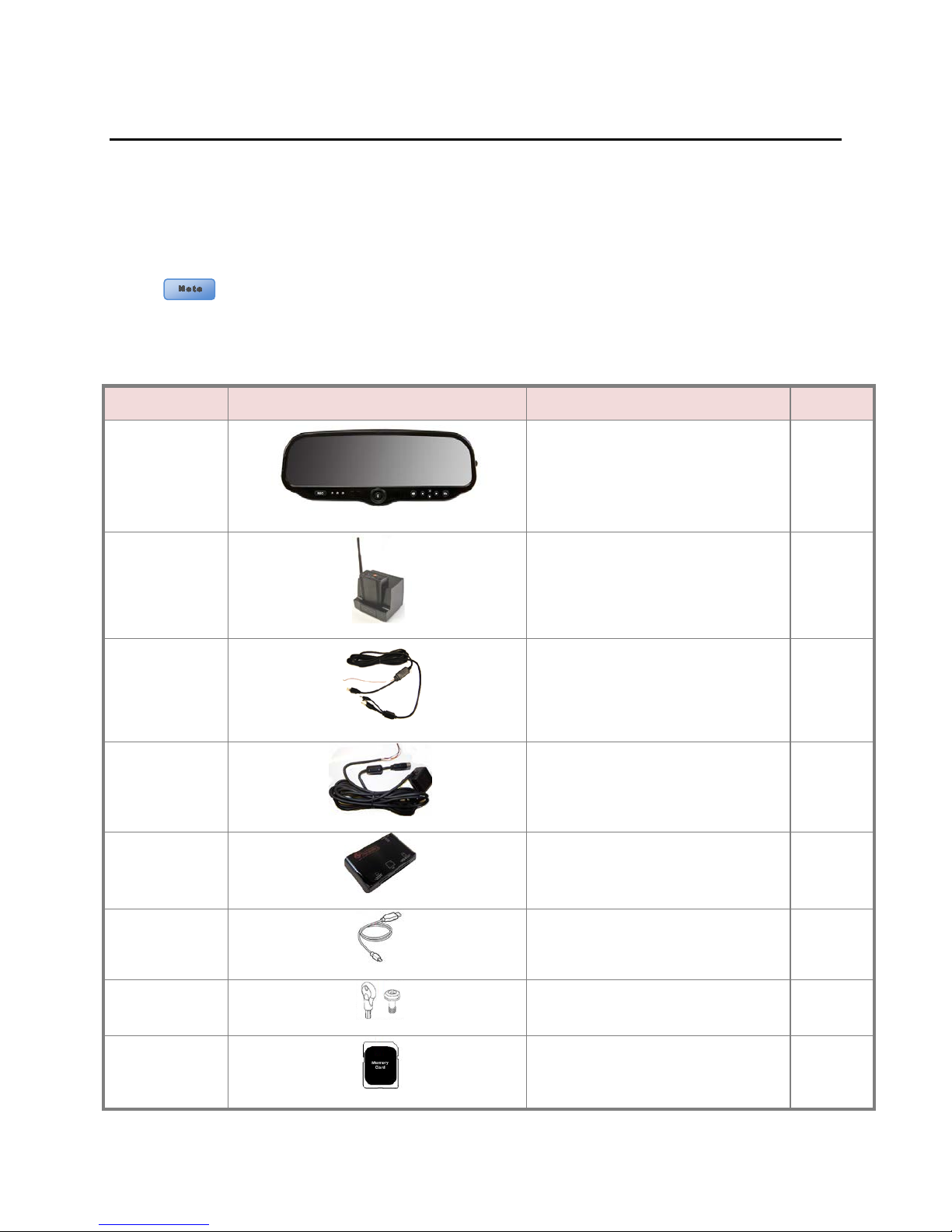
Cables and optional accessories are not incl ud ed in th e base DV M -100
package and are ordered separately. Refer to page
items.
Part Number
Image
Description
Quantity
Base mirror with mount & 8GB
Section - 2: Parts, Cables and Accessories
DVM-100
Parts and Accessories List
The diagram and table below outline the parts that are included with the DVM-100 Package.
006-08163-00
002-05095-00
008-01372-01
2-2 for a list of these
DVM-100
SD card
DWM-800 Wireless Microphone System 1
Cable Assembly, BTR800 to DVM-100 1
1
008-01373-01
002-00028-00
008-01271-00
259-00176-00
363-00046-00
Copyright © 2013 Digital Ally, Inc.
2-1
Power Cable Assembly 1
Card Reader 1
USB Cable 1
Security Key Kit 1
8 GB Memory Card 1
DVM-100 & DVM-400 Installation Guide 860-00187-00 REV A
Part Number
Image
Description
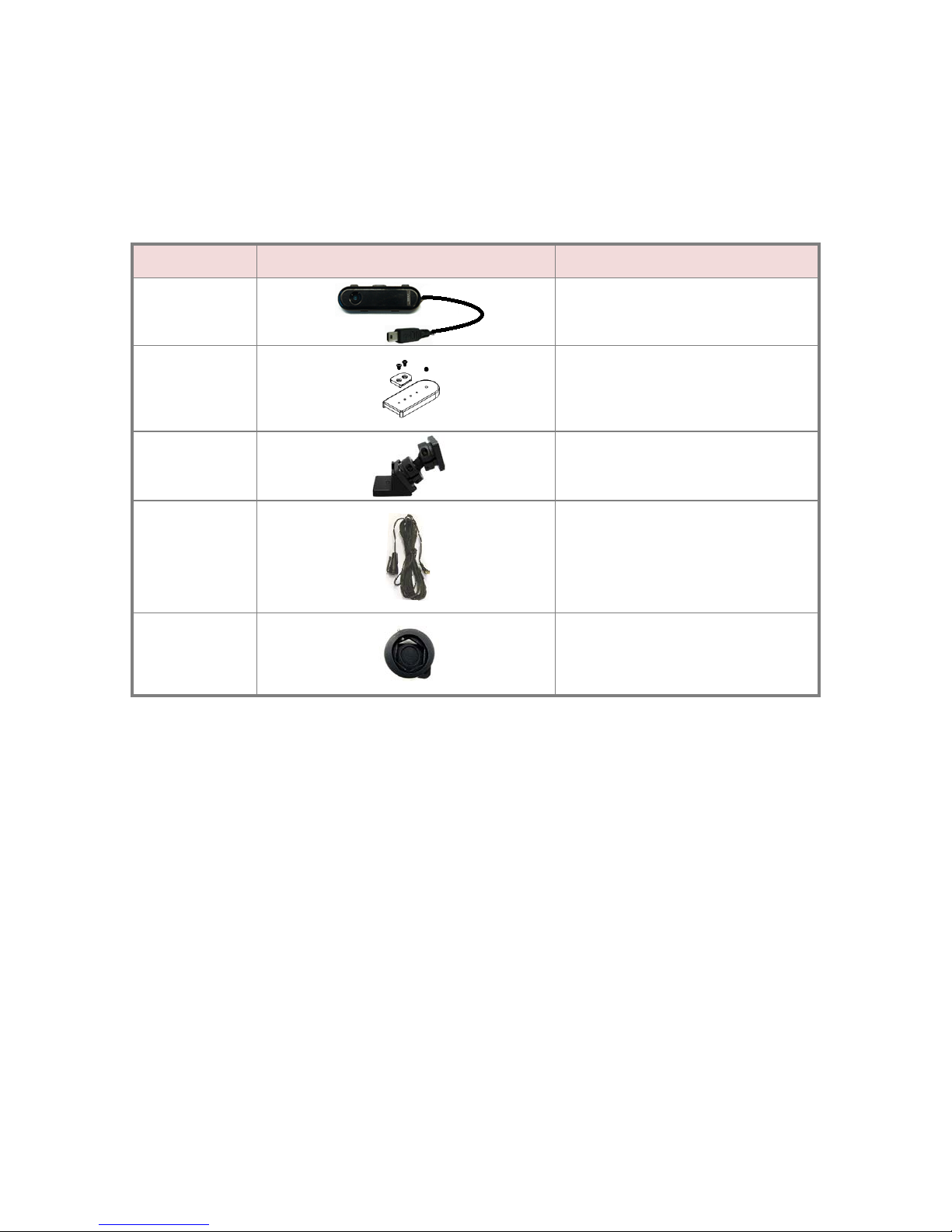
Cables and Optional Accessories
The table below outlines cables and optional accessories for the DVM-100 package.
001-00010-00
002-05030-00
002-05102-00
004-09058-00
002-05112-00
Wi-Fi Ass embly
Drop Mount
Big Ball Mirror Mount
Covert Rear Seat Microphone
Windshield Mount Adapter Kit ( 2011-
2012 Dodge Charger only)
Copyright © 2013 Digital Ally, Inc.
2-2
DVM-100 & DVM-400 Installation Guide 860-00187-00 REV A
Optional Wi-fi Antenna
Wireless microphone and charger
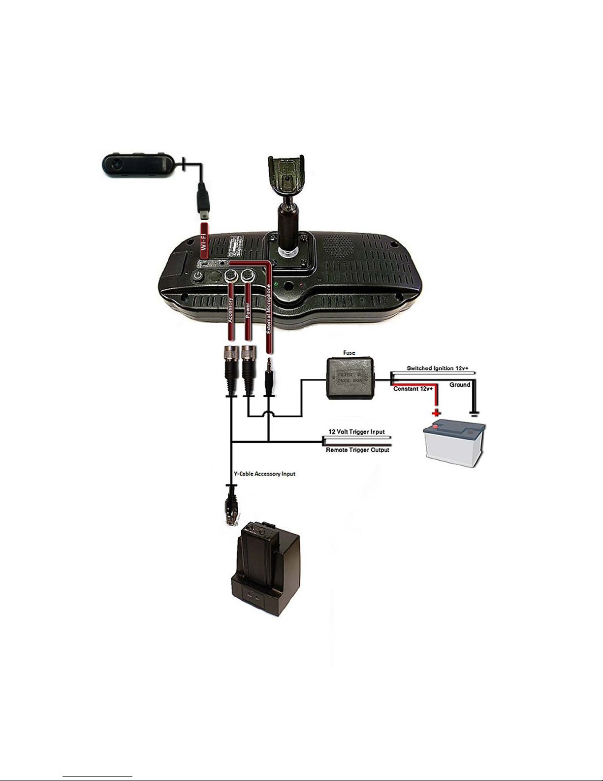
DVM-100 Wiring Diagram
Copyright © 2013 Digital Ally, Inc.
2-3
 Loading...