

Page 1

Quick Start Guide
Monroe Electronics.
All other trademarks are property of their respective owners.
Digital Alert Systems MultiPlayer™ Installation and
DASDEC™ Integration
Introduction
The Digital Alert Systems MultiPlayer (model DASMP) is uniquely designed four-channel (designated as Ports 1 thru 4) audio
player and program switcher for either radio or television facilities serving multiple program streams. The MultiPlayer works in
conjunction with a DASDEC and optional MultiStation™ software to provide completely independent EAS audio playout for up to
four discrete channels of EAS playback and program switching either simultaneously, sequentially, or with staggered start times
– the DASDEC handles EAS playout and switching for the 5th channel. This means a DASDEC and DASMP combination can
air any of the five channels at any time The DASDEC host communicates to character generators for television applications and
since MultiPlayer is a network based device it can be placed anywhere on a network accessible by the host DASDEC.
Each port on the MultiPlayer can be configured for either AES digital or analog mono, playback and program switching. Both
options use standard XLR’s. In addition the MultiPlayer expands the number of DASDEC GPI/O’s with four GPI’s and two
GPO’s per port available on a 10 position removable terminal strip.
Station In 1
Station Out 1
MultiPlayer™
Station In 2
Station In 3
Station In 4
Station In 5
Network
Exchange (TCP/IP)
DASDEC™ Integrated EAS/CAP
Figure 1 Station configuration of MultiPlayer and DASDEC combination.
Station Out 2
Station Out 3
Station Out 4
Station Out 5
IMPORTANT CONFIGURATION NOTES
Under DASDEC MultiStation™ control Station 1 is hardcoded to MultiPlayer Port 1. Station 2 is hardcoded to MultiPlayer Port 2
and so on. Station 5 is tied to the DASDEC internal audio program switch(es) as depicted in Figure 1.
Current MultiPlayer software supports AES at 48KHz, 32 KHz, and 44.1KHz.
Digital Alert Systems
A division of Monroe Electronics
585-765-1155 | fax 585-765-9330
100 Housel Ave. | Lyndonville | NY | 14098
www.digitalalertsystems.com
Revision: 4.0 Publication: DASMPQSG-0100
Copyright © 2014 Digital Alert Systems, a division of Monroe Electronics Inc. Information
herein is considered accurate at the time of publication. We constantly strive to improve our
products and services therefore some specifications are subject to change without notice.
DASEOC, DASDEC, MultiStation, and EAS-Net are trademarks of Digital Alert Systems and
Page 2
Digital Alert Systems MultiPlayer Quick Start Guide
Configuring MultiPlayer Network settings
The MultiPlayer’s factory default IP Address is 192.168.0.220. If connecting the MultiPlayer directly to the DASDEC via one of
the network expansion ports no change is necessary by configuring the DASDEC network port to use a similar address. If using
a network switch/router to connect the MultiPlayer and DASDEC the IP address will most likely need to be changed.
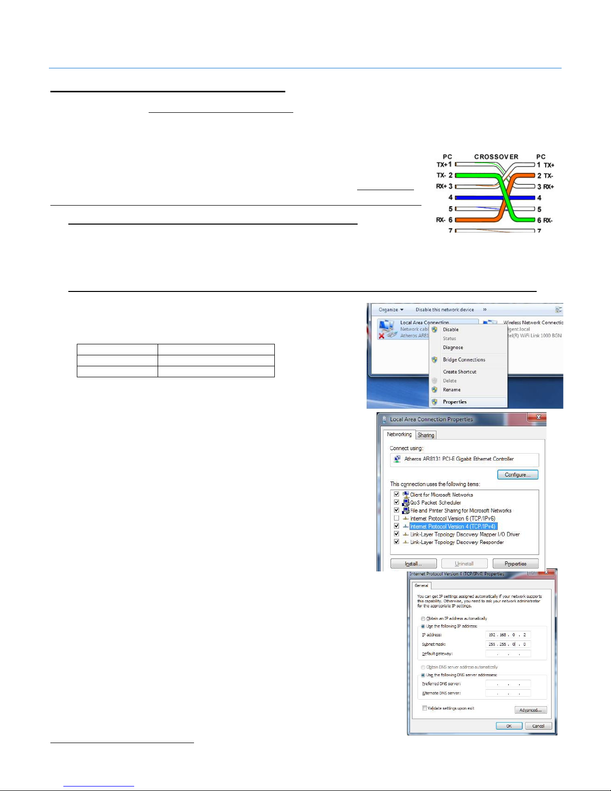
The MultiPlayer ships with a CAT-5 network crossover cable; this cable allows you to connect
directly to the network port on the MultiPlayer. Before directly connecting the MultiPlayer
verify you are using a crossover cable by referencing the picture in Figure 2. By not using a
crossover cable the connection will not work and one or both network ports may be damaged.
MultiPlayer Direct Network Connection to DASDEC
1. Connect the Ethernet crossover cable from the network connection
on the MultiPlayer into an open DASDEC Ethernet port, then skip to
Wiring the MultiPlayer
Figure 2 Ethernet crossover cable wiring
Setting/Modifying MultiPlayer IP address for Switch/router Connection to DASDEC
To assure connection with the DASDEC, the MultiPlayer should be
configured with a static IP address. Consult your IT department to determine
the following information:
Static IP Address _ _ _ . _ _ _ . _ _ _ . _ _ _
Gateway _ _ _ . _ _ _ . _ _ _ . _ _ _
Subnet Mask _ _ _ . _ _ _ . _ _ _ . _ _ _
To change the MultiPlayer’s IP address you will need a computer whose IP
settings can be modified. The following instructions are for a PC with
Windows 71.
1. On the computer open “Control Panel”, then open
“Network Connections”. Right-click on the network
connection you will be using to complete the setup and
select properties.
2. From the Network Connection Properties screen click on
“Internet Protocol Version 4 (TCP/IP), then click on the
“Properties” button.
Make a note of the current settings in the “Internet
Protocol Version 4 (TCP/IP)” properties page that opens
so you can reset the computer to these settings after
setting the IP Address of the MultiPlayer.
3. Next click the Radio Button for “Use the Following IP Address”.
4. In the “IP Address” field enter 192.168.0.200.
5. In the “Subnet Mask Field” enter 255.255.0.0. Leave the
“Default Gateway”, “Preferred DNS Server” and “Alternate DNS
Server” fields blank.
Click OK.
6. Connect the crossover cable from the MultiPlayer to the
computer
1
A Macintosh computer may also be used by modifying similar settings in Network Preferences under System Preferences
Revision 4.0 Page 2 of 13
Page 3
Digital Alert Systems MultiPlayer Quick Start Guide
7. Power up the MultiPlayer by inserting the AC cord and attaching to 100 – 240 VAC power source
8. While the MultiPlayer is booting (approximately 10 sec) open a web browser on the PC
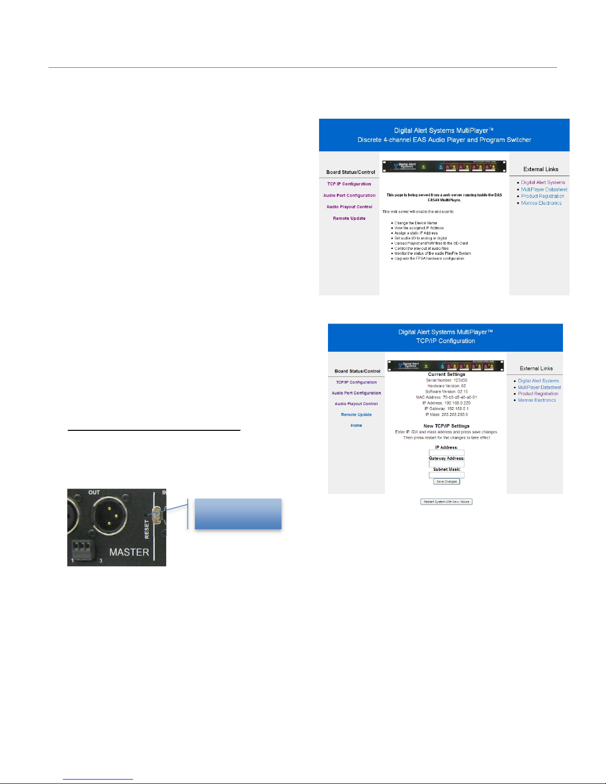
9. In the address line type 192.168.0.220 and
press Enter. You should be greeted with
the MultiPlayer Home page as shown in
Figure 3.
10. Click the link TCP/IP Configuration on the
left side of the page. The screen will
change to the TCP/IP configuration page
shown in Figure 4
11. Enter the previously obtained information
for IP Address, Gateway Address and
Subnet Mask in the associated fields.
12. Click Save Changes to store the values
13. Click Restart System with New Values
which will restart the MultiPlayer with the
Figure 3 MultiPlayer Home page
new values.
14. Disconnect the network connection and plug
into the network switch/router
15. Restore the computer’s previous TCP/IP values
by reversing the steps 1 – 6 above.
Resetting to Factory Default IP
Should it be necessary to reset the MultiPlayer to the default IP
Address (192.168.0.220), press and hold the RESET button, on the
back panel, for 10 seconds.
Reset button
(recessed)
Figure 4 MultiPlayer TCP/IP Configuration screen
Revision 4.0 Page 3 of 13
Page 4
Digital Alert Systems MultiPlayer Quick Start Guide
Audio Port Configuration
Units are shipped preset for AES playback on all ports. If all stations are using AES playback skip to Wiring the MultiPlayer.
The main point: Ports are assigned a channel, and channels are linked to a station in the DASDEC MultiStation interface.
Each MultiPlayer’s audio input/output ports can be configured to conform to the following signal types:
1. AES digital with input(stereo pair)-AES3
2. AES digital without input(stereo pair)-ORIG
3. Analog mono - ANALOG
4. Analog stereo - ANALOG + SLAVE combination
The different channels created by the MultiPlayer are linked to the different MultiStation stations in the DASDEC web
interface (do not confuse channels with ports). These rules and guidelines are explained below by use of screenshots from the
MultiPlayer web interface.
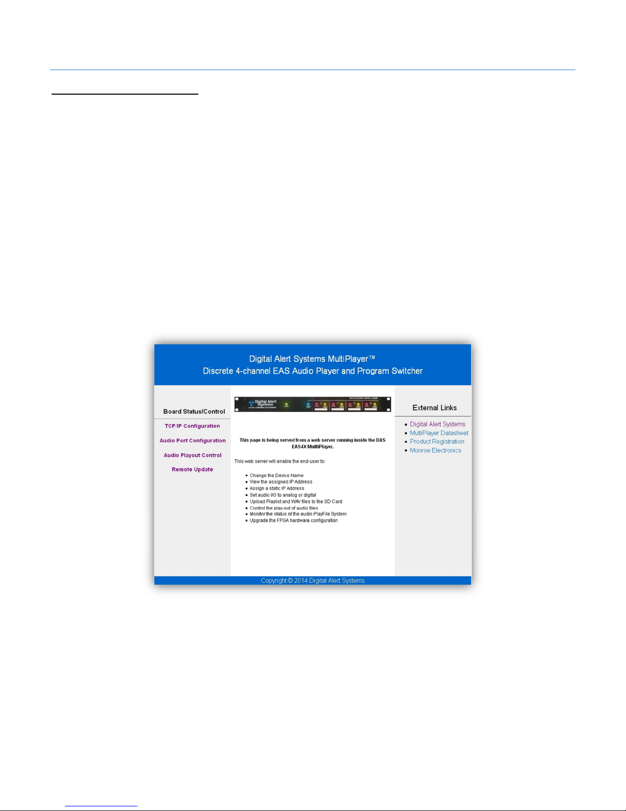
The screen shot in Figure 5 below is the home webpage for the MultiPlayer. To get to this page just type the IP address of the
MultiPlayer into a network connected web browser. Click Audio Port Configuration text link on the left to navigate to the Audio
Port Configuration page.
Revision 4.0 Page 4 of 13
Figure 5 MultiPlayer Home page
Page 5

Digital Alert Systems MultiPlayer Quick Start Guide
The next screenshot is the Audio Port Configuration page of the MultiPlayer. In this configuration, all of the channels are AES
digital channels. Port 1 is channel 1, port 2 is channel 2, port 3 is channel 3, and port 4 is channel 4. Each port is individual and
is not bonded to another port. In the DASDEC MultiStation interface, channel 1 would be seen as station 1, channel 2 would be
seen as station 2, channel 3 would be seen as station 3 and channel 4 would be seen as station 4. Therefore, 4 stations can be
configured in the MultiStation interface of the DASDEC.
The screenshot to the right shows the different channel
types that can be selected for port 1 using the dropdown
menu under each port name. While Port 1 was already
configured to be AES from earlier it can easily be changed
to Analog, or Originator.
With AES3 selected for the Port configuration, an input
source is required on the desired Port.
To use AES audio without an input source, “ORIG” must
be selected from the drop down menu, shown on the right.
Revision 4.0 Page 5 of 13
Page 6

DASDEC Multistation
DASDEC Multistation
DASDEC Multistation
DASDEC Mu
ltistation
Port 1=
DASDEC
Port 3=
DASDEC
Digital Alert Systems MultiPlayer Quick Start Guide
Analog audio can be used as a mono source for any port,
as shown to the right.
Analog audio can also be used as a stereo left and right
source. To use Analog audio as a stereo source, Port 1
would need to be set to “ANALOG” and Port 2 would need
to be set to “SLAVE”. This forms a bonded pair.
An analog stereo source can also be configured for ports 3
and 4. Port 3 would need to be set to “ANALOG” and Port
4 would need to be set to “SLAVE”. This forms a bonded
pair.
The screenshot on the right shows 2 Analog stereo
sources being used.
*The Slave option can only be selected for Ports 2 and 4
With 2 Analog stereo sources set for the Multiplayer, Ports
1 and 2 are now Station 1 in the DASDEC Multistation
Interface. Ports 3 and 4 would be Station 3 in the
DASDEC Multistation Interface.
Interface: Station 1
Interface: Station 3
If only one Analog Stereo source is to be used, then the
Ports can be arranged in one of 2 ways.
If Ports 1 and 2 are configured as an Analog Stereo
source, Ports 1 and 2 are now Station 1 in the DASDEC
Multistation Interface. Port 3 is Station 3 in the DASDEC
Multistation Interface and Port 4 is Station 4 in the
DASDEC Multistation Interface.
Ports 3 and 4 can be set to AES, Analog, or ORIG
Interface: Station 1
Multistation Interface:
Station 3
Port 4= DASDEC
Multistation Interface:
Station 4
depending on the sources being used.
If Ports 3 and 4 are configured as an Analog Stereo
source, Ports 3 and 4 are now Station 3 in the DASDEC
Multistation Interface. Port 1 is Station 1 in the DASDEC
Multistation Interface and Port 2 is Station 2 in the
DASDEC Multistation Interface.
Ports 1 and 2 can be set to AES, Analog, or ORIG
depending on the sources being used.
Multistation Interface:
Station 1
Port 2= DASDEC
Multistation Interface:
Station 2
Interface: Station 3
You must make your selections for each Port when you would like to make a change. Once a selection has been made
for all of the ports, click on Save Changes. To ensure that your settings have saved, click the refresh button. If your
configuration remains the same below the pull down menus, then your settings have been saved.
Revision 4.0 Page 6 of 13
Page 7

DASDEC
MultiStation
Number
Port 1
Port 2
Port 3
Port 4
Digital Alert Systems MultiPlayer Quick Start Guide
Wiring the MultiPlayer
Program Audio
Wiring the MultiPlayer is very straightforward. Audio connections are made for each of stations through the ports. Recall
Under DASDEC MultiStation control Station 1 is hardcoded to MultiPlayer Port 1. Station 2 is hardcoded to MultiPlayer Port 2
and so on with Station 5 is tied to the DASDEC internal audio program switch(es) as depicted in Figure 1.
Figure 6 DASDEC and MultiPlayer audio program wiring configuration
The MultiPlayer features automatic program bypass in the event of power fail. In this way the program input will automatically be
routed to the program output should power be loss or by command from the DASDEC.
1. For a digital or mono audio connection, make the program audio connections as follows
MultiPlayer Connection
(Order in the MultiStation pull-down menu after Base Station)
Setup > Decoder > Forwarding
DASDEC MultiStation 1
DASDEC MultiStation 2
DASDEC MultiStation 3
DASDEC MultiStation 4
DASDEC MultiStation 5
MASTER
(DASDEC AES output loops through the MultiPlayer’s MASTER
port to provide “live” audio during an EAN)
Revision 4.0 Page 7 of 13
Page 8

MP Port 1: Relay
1 Pin 1
MP Port 1: Relay 2
Pin 1
GPI 1
MP Port 1: Input 1
GPI 2
MP Port 1: Input 2
GND Ground
MP Port 1: Relay 1
Pin 2
GPI 3
MP Port 1: Input 3
GND Ground
MP Port 1: Relay 2
Pin 2
GPI 4
MP Port 1: Input 4
MP Port
2
: Relay
1 Pin 1
MP Port
2: Relay 2
Pin 1
GPI 1
MP Port 2:
Input 1
GPI 2
MP Port 2: Input 2
GND Ground
MP Port 2: Relay 1
Pin 2
GPI 3
MP Port 2: Input 3
GND Ground
MP Port 2: Relay 2
Pin 2
GPI 4
MP Port 2: Input 4
MP Port
3
: Relay
1 Pin 1
MP Port
3: Relay 2
Pin 1
GPI 1
MP Port 3: Input 1
GPI 2
MP Port 3: Input 2
GND Ground
MP Port 3: Relay 1
Pin 2
GPI 3
MP Port 3: Input 3
GND Ground
MP Port 3: Relay 2
Pin 2
GPI 4
MP Port 3: Input 4
MP Port
4: Relay
1 Pin 1
MP Port
4: Relay 2
Pin 1
GPI 1
MP Port 4: Input 1
GPI 2
MP Port 4: Input 2
GND Ground
MP Port 4: Relay 1
Pin 2
GPI 3
MP Port 4: Input 3
GND Ground
MP Port 4: Relay 2
Pin 2
GPI 4
MP Port 4: Input 4
Digital Alert Systems MultiPlayer Quick Start Guide
MultiPlayer GPI’s & GPO’s
The MultiPlayer features four (4) General Purpose Inputs and two (2) General Purpose outputs per each port. The table and
picture below define the wiring locations and the corresponding labeling in the DASDEC. It is important to match the connection
and labeling in the next section STEP 4 - Configuring the MultiPlayer GPI’s and GPO’s. Note: GPO’s are not grounded,
having two connections (Pins 1 and 2). The terminal strip is removable to facilitate ease of wiring.
Port 1 Connection
Pin 1 GPO 1
Pin 2 GPO 2
Pin 3
Pin 4
Pin 5
Pin 6 GPO 1
Pin 7
Pin 8
Pin 9 GPO 2
Pin 10
DASDEC Label
(Setup > GPIO > MultiPlayer GPIO)
Port 2 Connection
Pin 1 GPO 1
Pin 2 GPO 2
Pin 3
Pin 4
Pin 5
Pin 6 GPO 1
Pin 7
Pin 8
Pin 9 GPO 2
Pin 10
DASDEC Label
(Setup > GPIO > MultiPlayer GPIO)
Port 3 Connection
Pin 1 GPO 1
Pin 2 GPO 2
Pin 3
Pin 4
Pin 5
Pin 6 GPO 1
Pin 7
Pin 8
Pin 9 GPO 2
Pin 10
DASDEC Label
(Setup > GPIO > MultiPlayer GPIO)
Port 4 Connection
Pin 1 GPO 1
Pin 2 GPO 2
Pin 3
Pin 4
Pin 5
Pin 6 GPO 1
Pin 7
Pin 8
Pin 9 GPO 2
Pin 10
DASDEC Label
(Setup > GPIO > MultiPlayer GPIO)
Revision 4.0 Page 8 of 13
Page 9

Digital Alert Systems MultiPlayer Quick Start Guide
Configuring the DASDEC for MultiPlayer Audio Playout
Step 1 – Install the MultiPlayer supported software
The DASDEC must have version 2.5-1_a07 software or higher to work with the MultiPlayer. To download this version, click this
link: www.digitalalertsystems.com/MultiPlayer_documents.html and follow the table information to get the necessary DASDEC
software file then go to Setup > Server > Upgrade and follow standard DASDEC upgrade procedures to install this new
software version.
Once the DASDEC is upgraded with the proper software version it can be configured to control the MultiPlayer.
Step 1B – Configure the Network Interface
(Direct MultiPlayer Connection Only)
If using a direct MultiPlayer to DASDEC connection via one of the expansion
Ethernet ports you need to be sure it is enabled and configured properly.
Configuring a Network Interface
1. Log In to the DASDEC
2. Go to Setup > Network > Configuration
3. Enable the proper network interface connecting the
Figure 7 DASDEC with optional Ethernet expansion
MultiPlayer by clicking the check box. See
example in
Figure 8
using the Third
Network Interface shown
4. Enter 192.168.0.200 in the IP Address field
(or any IP address in the same range as the
MultiPlayer – DO NOT ENTER THE
MULTIPLAYER IP ADDRESS HERE)
5. Enter 255.255.255.0 in the IP Netmask field
6. Leave the Hostname field alone. It should
read dasdecnicX.net where “X” is the port
number being configured.
7. Scroll down the page and click
Accept Changes / Restart Network
8. The DASDEC will restart and the box will
change to green as shown in
Figure 9
Figure 8 Enabling Ethernet expansion port for MultiPlayer direct
connection
Revision 4.0 Page 9 of 13
Figure 9 Expansion Ethernet port enabled indicated by
*Enabled* message and green outline
Page 10

Digital Alert Systems MultiPlayer Quick Start Guide
Step 2 – Enabling MultiPlayer Support on the DASDEC
1. Log in to the DASDEC
2. Go to Setup > Audio > MultiPlayer (the MultiPlayer tab only appears in the latest version of
DASDEC software featuring MultiPlayer support, with the Multistation License Key enabled)
3. Enable the MultiPlayer by checking the box Enable MultiPlayer Interface. The screen will
expand to allow additional entries.
4. Enter the MultiPlayer’s IP address in the MultiPlayer IP Address field. (If using the Direct
Multiplayer to DASDEC Connection, enter the Multiplayer’s default IP of 192.168.0.220)
5. Enter the word “guest” (all lowercase, no spaces and no quotations) in BOTH the MultiPlayer
FTP User Name and MultiPlayer FTP Password fields
Enter the MultiPlayer’s
IP address
Enter the word guest
Enter the word guest
Figure 10 MultiPlayer configuration screen
6. Once the network information is entered, the DASDEC will attempt to verify connection to the
MultiPlayer.
If there is a connection issue the message Ping test to xxx.xxx.xxx.xxx Failed! (where
xxx.xxx.xxx.xxx is the IP address entered in the MultiPlayer IP Address field above) will appear.
If the test fails, verify the MultiPlayer’s IP Address is entered correctly, recheck all cables are
properly connected, and verify the network settings for the connection to the MultiPlayer are
correct. If the MultiPlayer is on a network switch/router you can access it from any web-browser
by typing its IP address in to the address field and seeing if the MultiPlayer Home page is
reachable.
7. Click Accept Changes
Revision 4.0 Page 10 of 13
Page 11

Digital Alert Systems MultiPlayer Quick Start Guide
8. Switch to the Setup > Audio > Audio Output Levels/Test tab
9. Ensure the Audio Output Sample Rate is set at 16000 Sample/sec by selecting it in the pull-
down menu.
(Note: This merely sets the sampling rate for the monophonic EAS audio and DOES NOT impact
the AES input and output rates.)
Ensure this selector is set
at 16000 Sample/sec
Figure 11 Setting the audio sample rate for EAS audio. See text for more information.
10. Once selected the change is immediately applied.
11. If you are using Analog Audio for the MultiPlayer, you must set the EAS Header/Tone/EOM
Amplitude percent to 40. Once you have changed the value press enter. The changes will be
applied.
12. If you have changed the EAS Header/Tone/EOM Amplitude percent from the default value of
80, you must go to the Setup > Audio > Multiplayer page. Scroll to the bottom and click the Init
Multiplayer button. This will load a new Attention Signal and End of Message Tone, using the
new amplitude percent you have set.
Revision 4.0 Page 11 of 13
Page 12
Digital Alert Systems MultiPlayer Quick Start Guide
Step 3 – Configuring the stations for MultiPlayer audio playout
1. Log in to the DASDEC
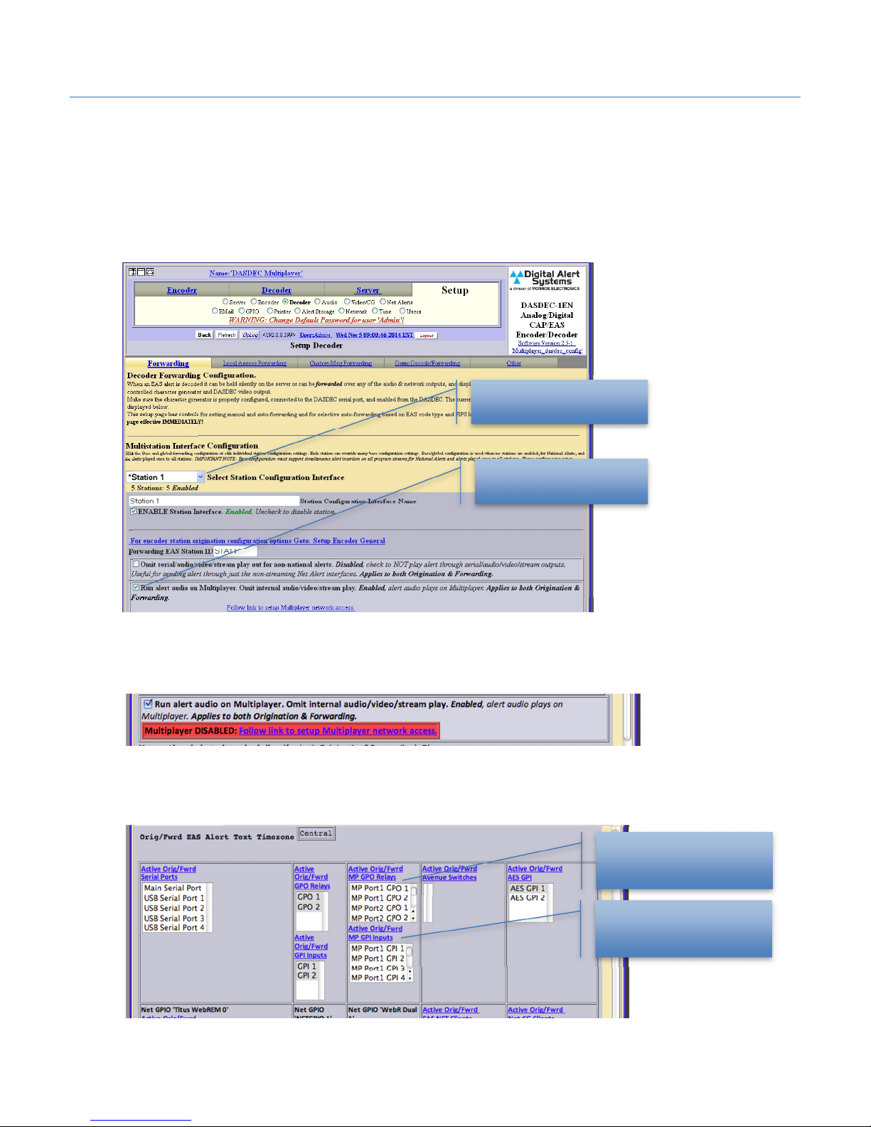
2. Go to Setup > Decoder > Forwarding
3. Scroll down to the MultiStation Interface Configuration section
4. Use the Select Station Configuration Interface pull down to select the station to activate
5. Click the check box Run alert audio on MultiPlayer.
Select Station to modify
Enable MultiPlayer on this
station by checking box
Figure 12 Configuring each station for MultiPlayer audio playout. (Repeat for each active station)
6. If the MultiPlayer is not connected to the DASDEC you will see the warning message as shown in
Figure 13. (If necessary follow the steps in STEP 2 -6 above to verify connectivity.)
Figure 13 Warning message if MultiPlayer is not connected or inoperative.
7. Scrolling down to the station action table there’s an additional field for assigning the MultiPlayer
GPI and GPO’s to a station. You may want to skip to STEP 4 – Configuring the MultiPlayer GPI’s
and GPO’s where specific actions are assigned before assigning the ports.
Assign any MultiPlayer
GPO to the station
Figure 14 MultiStation action table assignments.
Revision 4.0 Page 12 of 13
Assign any MultiPlayer
GPI to the station
Page 13
Digital Alert Systems MultiPlayer Quick Start Guide
8. Select any of the MultiPlayer GPI’s or GPO’s you wish to assign to this station holding the SHIFT
key or Control key (Command key for Mac users) for multiple selections.
Refer to the MultiPlayer GPI’s & GPO’s section of this document for more on ports
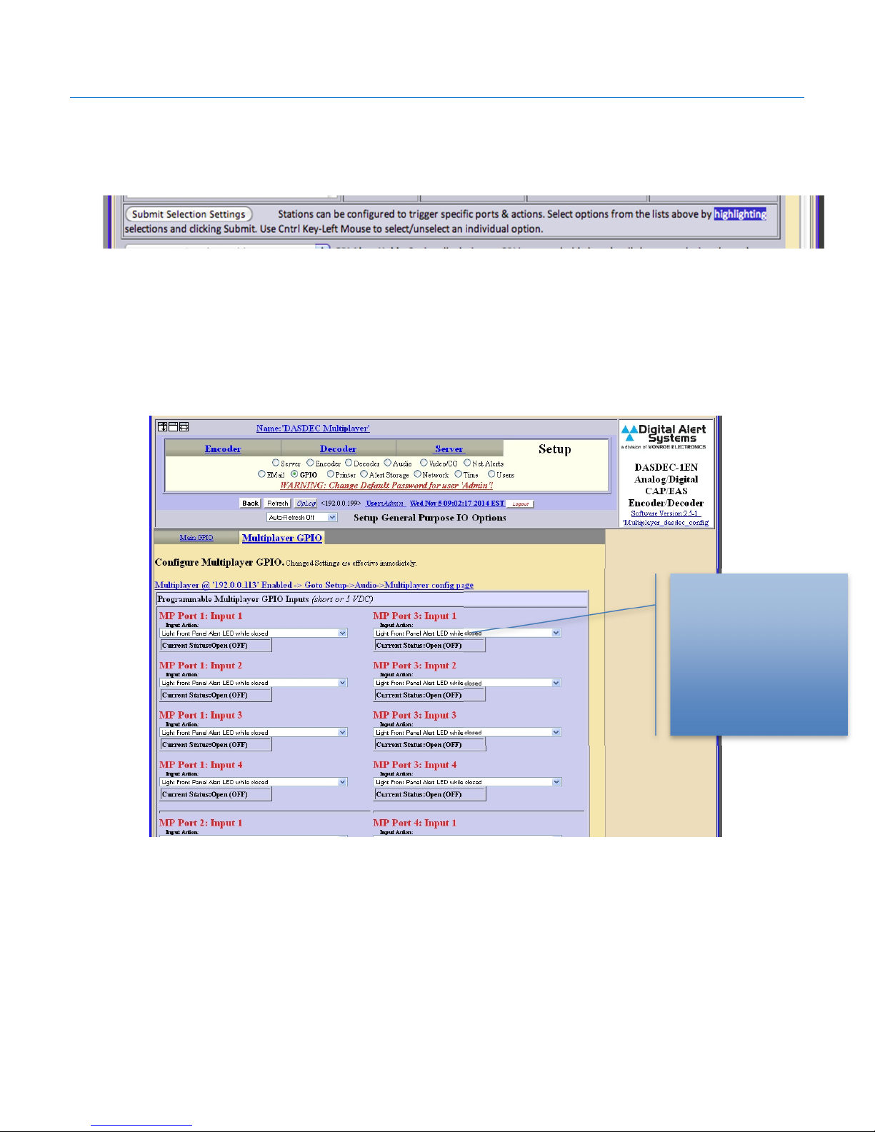
9. Click .Submit Selection Settings to save the station settings.
10. Repeat Steps 3-4 thru 3- 9 for each station.
Step 4 – Configuring the MultiPlayer GPI’s and GPO’s
1. Log in to the DASDEC
2. Go to Setup > GPIO > MultiPlayer GPIO
3. Using the pull down selections to define the action for each input or output.
SELECTIONS ARE IMMEDIATE
Use pull-down to select
Selections are applied
Repeat on each port as
Figure 15 MultiPlayer GPI and GPO configuration page. Selections are immediate.
4. If you haven’t assigned the MultiPlayer GPI’s or GPO’s to a station you may want to return to
STEP 3 -7 and complete the station action table assignments.
desired action
immediately
needed
Revision 4.0 Page 13 of 13
 Loading...